

Page 1
ANCHOR MODULES
ASSEMBLY INSTRUCTIONS
30’, 40’ AND 60’ WIDE SYSTEMS
SALES OFFICES:
1100 BURCH DRIVE
P.O. BOX 3477
EVANVILLE, IN 47733 USA
PH. 812-867-2421 • FAX 812-867-0547
E-mail: tents@anchorinc.com• www.anchorinc.com
Quality, Craftsmanship and Service since 1892
MODS 0907
Page 2
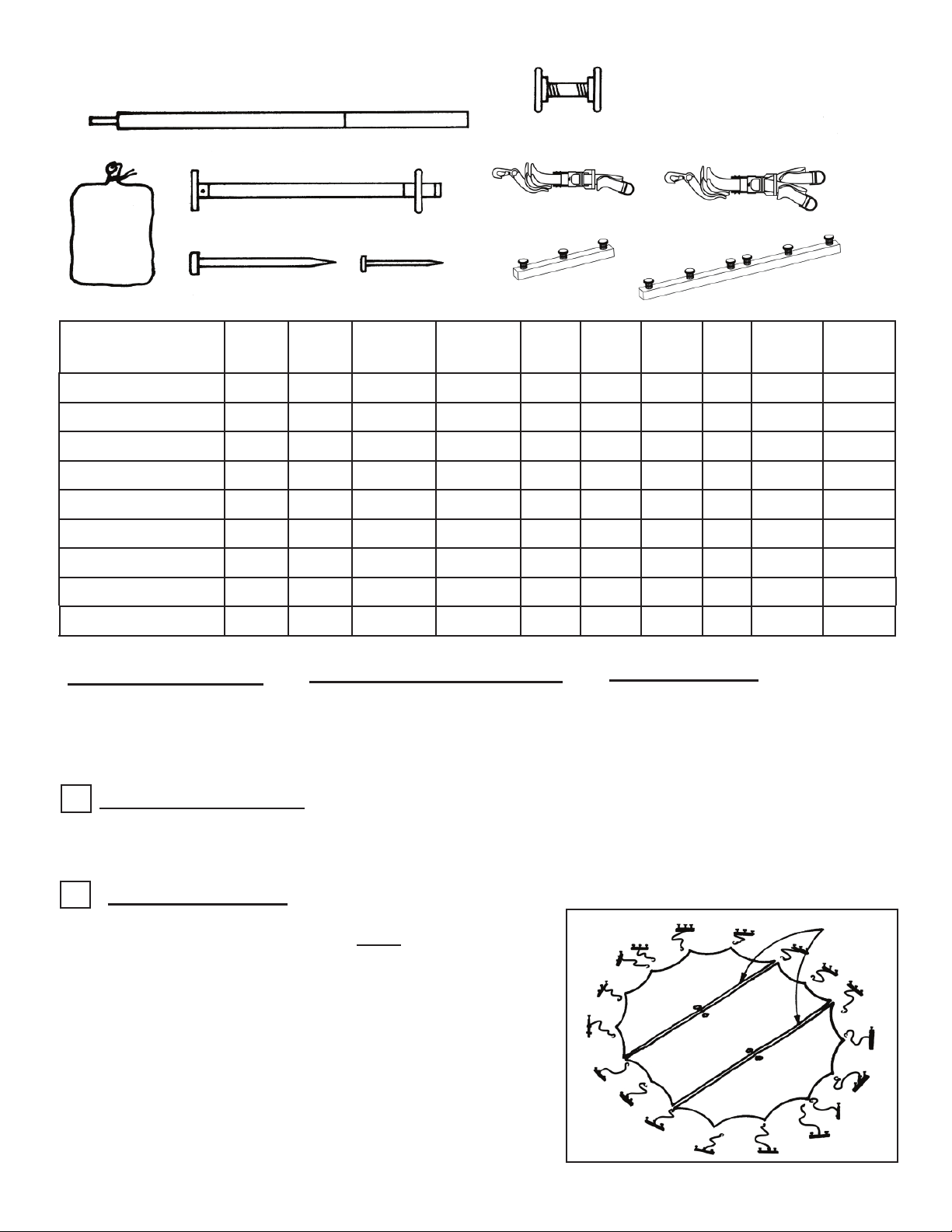
MODULE TENT PARTS LIST
2 PC CENTER POLE
PIPE & FLANGES
TOOLS REQUIRED
Sledge Hammers
Stake Driver
(2) Measuring Tapes
3/4” Wrench
BAG
WITH
EACH
SECTION
30’ ENDS (PAIR)
30’ MIDDLE
30’ CENTER
40’ ENDS (PAIR)
40’ MIDDLE
40’ CENTER
60’ ENDS (PAIR)
60’ MIDDLE
40’ x 60’ CENTER
SIDE POLE WITH BASE
PLATE AND TOP OVAL RING
42” STEEL STAKE
CENTER
POLES
POLES
1 12 14 - 42 14 - 24 2 1
1 4 4 - 12 4 - 8 1 1
2 - 4 - 12 4 - - 1 2
1 12 14 - 42 14 - 24 2 1
1 4 4 - 12 4 - 8 1 1
2 - 4 - 12 4 - - 1 2
2 16 - 32 96 - 16 32 2 2
2 4 - 8 24 - 4 8 1 2
3 - - 8 24 - 4 - 1 3
SIDE
10” NAIL STAKE
WEB GUYS
SINGLE
YOKE
2’-0” STAKE BAR
WEB GUYS
DOUBLE
YOKE
WEB GUY WITH
SINGLE-YOKE
2’-0”
STAKES
STAKE
BAR
WEB GUY WITH
DOUBLE-YOKE
4’-0” STAKE BAR
4’-0”
STAKE
BAR
NAILS
10”
BAG
WITH
SECTION
PIPE
&
FLANGES
LAYOUT & CHECK
Use the parts list above for a
quick I.D. and as a check list
to ensure that you have all
the parts.
MANPOWER REQUIRED
Three experienced installers
should be able to assemble a 30’
wide tent. Four would be needed
for a 40’ wide, and five for a 60’
wide tent.
MEASURE LAYOUT
1
Mark the location of stakes, side poles and center poles.
Proper placement of center and side poles is critical for proper
tensioning of the tent. (See pages 4, 5 & 6 for tent layouts.)
LAYOUT AT SITE
2
Drive stakes vertically through stake bars & D-rings of single or
double yokes of web guys with D-rings under stake bars. (See
Parts list above for definition of which stake bars and web guys to
use with your size tent.)
Insert web guys loosely into ratchets.
Spread drop cloths and unroll the tent.
Any objects with sharp projections, which must remain on the site
under the tent should be padded and taped.
INSPECT SITE
CAUTION: Consult the local utility
company prior to installation.
Prior to assembly, be sure to look
around the area for obstacles, pipes,
wires, etc.
LACE
END
MIDDLE
END
NOTE: Match the loop edges to the hole edges of sections for
lacing.
2
Page 3
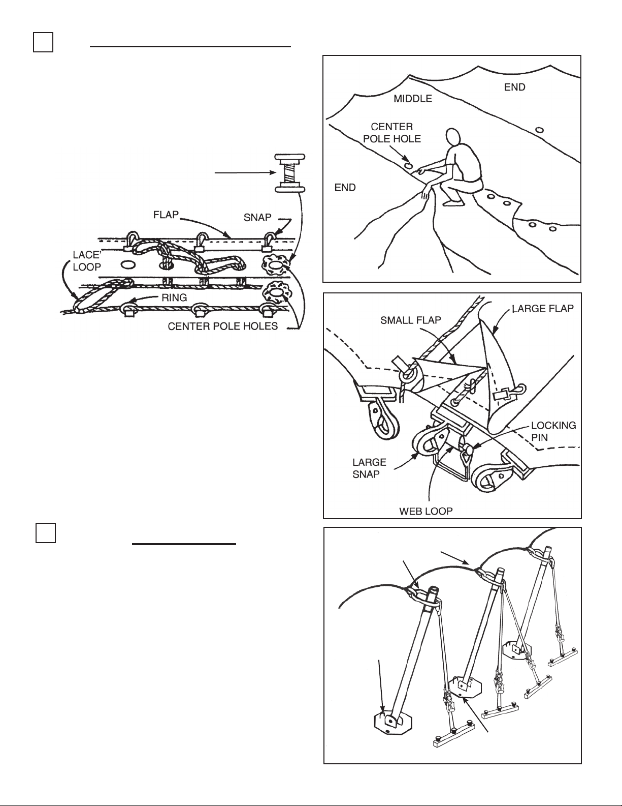
3
LACING INSTRUCTIONS
With tent sections on the ground, overlap the center
pole hole with the grommet side on top. At the center
pole locations with overlapping holes, place the pipe
through the holes and attach flanges at both ends.
Pipe flanges are furnished at each laced center pole
hole location.
PIPE & FLANGE
For 60’ tent, lace from one center pole to the other.
Starting at the center pole hole, push the first loop
through corresponding grommet.
Continue the lacing process and cover the lacing
with the protective flaps and snap to the rope as
you move down the tent section.
Tie off the last long lacing loop.
Push the web loop through the opening on the
large snap and secure it with the locking pin.
4
SIDE POLES
Place assembled side poles around the perimeter
of the tent.
Start at downwind side. Snap the web guys and
tent to the side poles. Set up side poles with the
base plate at the marked location. Secure baseplates with 10” nail stakes.
The bottom of the side poles should be pointed
inward toward the center of the tent. Continue with
each side pole around the perimeter of the tent.
LARGER END OF
RING TOWARD
INSIDE OF TENT
RING ON
BASEPLATE
TOWARD INSIDE
OF TENT
WIND DIRECTION
10” NAIL
STAKES THRU
BASE PLATES
3
Page 4

5
RAISE CENTER POLES
Raise the center poles nearest to the
wind direction to approximate the position. Position one installer to guide the
center pole pin through the hole to prevent snagging or tearing of the fabric as
the pole is being raised to position.
Tie off the jump rope.
At this point it is required to properly
anchor bases of all center poles to prevent movement.
JUMP ROPE
6
TENSION SIDE POLES
Tension web guys with ratchets.
Protective covers are recommended for
all stakes.
JUMP ROPE
2’-8”
RATCHET
WEB GUY WITH SINGLE YOKE
SHOWN WITH 2’-0” STAKE BAR.
7
TAKE DOWN
USE EXTREME CAUTION WHEN
REMOVING ALL POLES
1. Spread the ground cover.
2. Slant the side poles inward.
3. Remove the center and side poles.
4. Reverse the installation steps.
IMPORTANT
Check the web guys periodically for tightness and good condition.
Store the tent in a cool, dry area. Never
store the fabric wet or damp.
4
Page 5

END
ANCHOR MODULES - 30’
MIDDLE
END
POLE & STAKE LOCATIONS
CENTER
END
5
Page 6

END
ANCHOR MODULES - 40’
END
MIDDLE
CENTER
POLE & STAKE LOCATIONS
6
END
Page 7

40’ END
60’
END
(LOOP)
40’ x 60’
CENTER
ANCHOR MODULES - 60’
60’
MIDDLE
POLE & STAKE LOCATIONS
60’
END
(HOLE)
7
Page 8

EVANSVILLE, INDIANA
Thank you for purchasing an Anchor product. In return, we pledge Quality, Service
and Craftsmanship and are available for any questions you may have or assistance
you may need.
PHONE NUMBER
812-867-2421
FAX NUMBER
812-867-0547
Anchor products are of superior design and operate best within the parameters of these
instructions. It is IMPERATIVE that the instructions be carefully read and COMPLETELY
FOLLOWED. Please read installation instructions before the installation or removal of
this product. Installation instructions are available at www.anchorinc.com.
CAUTION
1. For each installation, the installer is solely responsible for evaluating the site and the
proper securing method determined. Some soils require different staking or securing than
that provided with the tent. Due to this variety of soil conditions, these are the manufacturer’s suggested sequence of installation procedures. Anchor’s responsibility is limited
to the construction of the tent. We are not responsible for methods that installers may
choose to secure the tent to the ground.
2. Inasmuch as the weather is unpredictable, good judgment and common sense must
be incorporated within installation guidelines. It is the responsibility of the tent installer/
maintainer to determine the severity of the weather, proper time and method of installation
and/or erection and disassembly.
This product has been manufactured for use as a temporary structure. For the safety of
all occupants, evacuation is recommended if threatening weather occurs, or if there is any
doubt concerning the safe use of this product.
3. Proper safety equipment should be used at all times to insure a safe installation and
take down. We suggest a careful evaluation be made to determine safety equipment
needed, such as hard hats, steel-toe shoes, safety glasses and other as required.
4. Anchor stands behind its products in accordance with its standard Terms and
Conditions of sale. A copy of our Terms and Conditions of Sale can be obtained by contacting Anchor at the telephone number and/or address on this document.
28.2 11-01-02
 Loading...