

Page 1
Assembly Instructions
20’ x 24’ Light Expeditionary Shelter
With Extension Kits
Please read all assembly instructions before the installation or removal of this product.
Assembly Instructions are also available on the web at: www.anchorinc.com
Sales Offices
1100 Burch Dr
P O Box 3477
Evansville, IN 47733
Phone (812) 867-2421
Fax (812) 867-0547
(800) 544-4445
Production Facilities
Evansville, IN
LES 06-06
Page 2
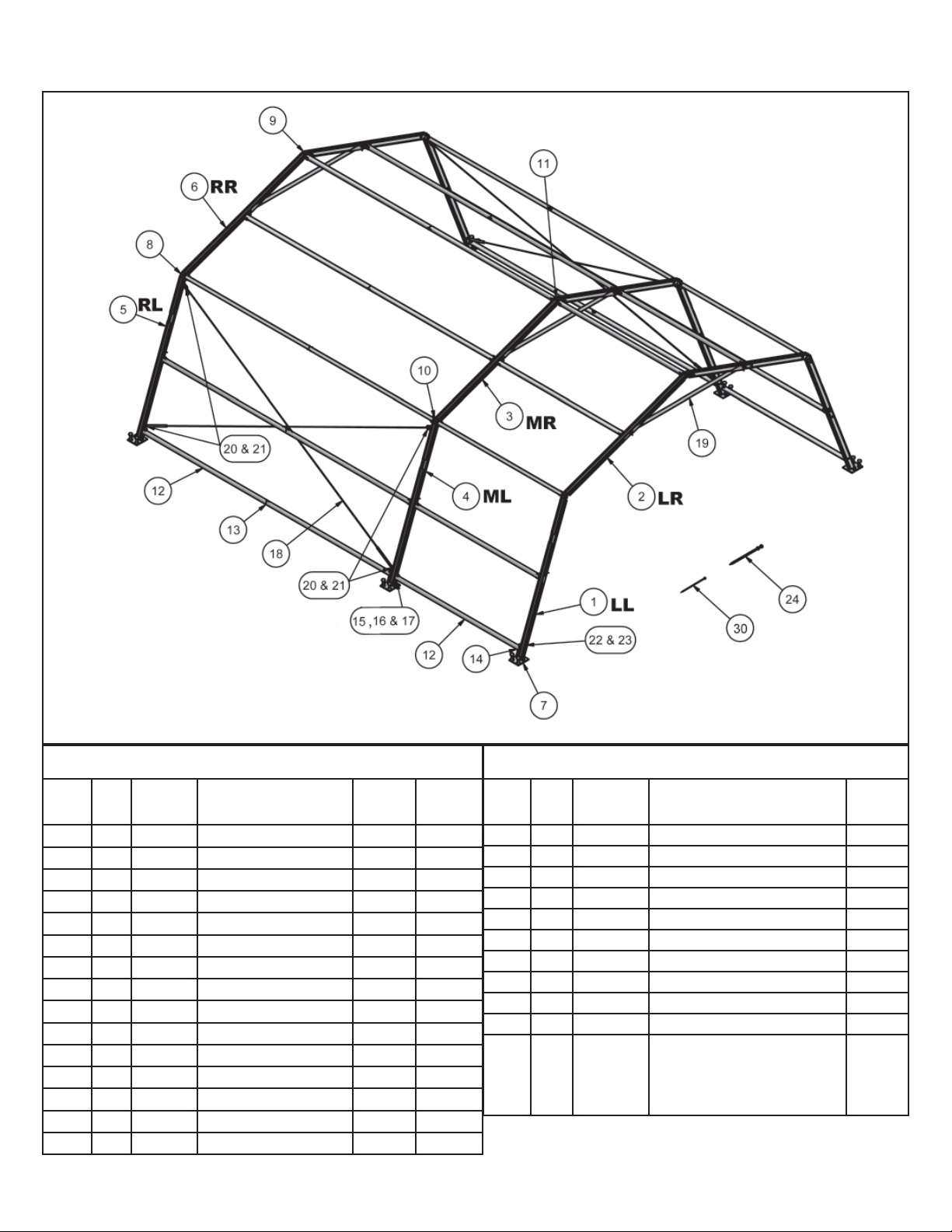
LES Standard Frame Terminology and Parts List
LES (20’ x 24’) Parts List
Item
No weight is listed for items under one pound.
*
Qty Part No. Description
No.
1 2 80856 Left Leg 27.0
2 2 80816 Left Rafter 20.6
3 2 80819
4 2 80857 Mid Leg 30.0
5 2 80855 Right Leg 27.0
6 2 80846 Right Rafter 20.6
7 6 80839 Base Plate Weldment 7.6
8 4 80824 Eave End Weldment 9.9
9 2 80827 Peak End Weldment 9.8
10 2 80828 Eave Mid Weldment 9.9
11 1 80829 Peak Mid Weldment 9.8
12 27 80830 Half Purlin 7.7
13 9 80831 Purlin Splice 2. 2
14 8 80836 Bottom Purlin Reinf. 15 8 3023897 J Bolt -
Mid Rafter
2
Pounds
per Item
21.2
Label
LL
LR
MR
ML
RL
RR
LES (20’ x 24’) Parts List (cont’d)
Item
Qty Part No. Description
No.
16 8 3025387 Washer 17 8 3024390 Wing Nut -
18 4 80871 Cable for 16’-0” Bay 5.0
19 3 3582260 Ridge Brace 16.4
20 8 3023260 3/8” x 3” Bolt 21 8 3024015 Eye Nut 22 2 3023246 3/8” x 2 3/4” Bolt 23 2 3024445 3/8” Nylock Nut 24 12 3704230 Dbl. Hd. Stake (1” x 30”) 8.0
30 12 3704024A Stakes (5/8” x 24”) 5 .0
Installation Kit:
31 1 8003720
(2) Pull ropes (31a)
(1) Zipper tool (31b)
(4) Frame lifts (31c)
NSN: 20’ x 24’ LES (Green Fabric) 8340-01-537-0712
Pounds
per Item
25.0
Page 3
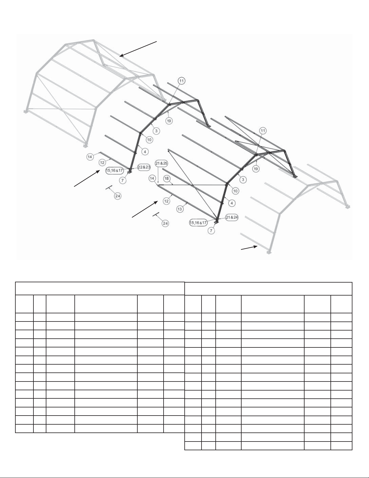
8’-1 3/4”
Extension
LES Frame Extensions Terminology
Standard frame parts
shown ghosted.
16’ Extension
8’ Frame Extension Kit
Item
Qty Part No Description
No.
3 2 80819 Mid Rafter 21.2
4 2 80857 Mid Leg 30.0
7 2 80839 Base Plate Weldment 7.6
10 2 80828 Eave Mid Weldment 9. 9
11 1 80829 Peak Mid Weldment 9. 8
12 9 80830 Half Purlin 7.7
14 4 80836 Bottom Purlin Reinf. 15 4 3023897 J Bolt 16 4 3025387 Washer 17 4 3024390 Wing Nut 19 1 3582260 Ridge Brace 16.4
22 2 3023246 3/8” x 2 3/4” Bolt 23 2 3024445 3/8” Nylock Nut 24 4 3704230 Dbl. Hd. Stake -1 x 30 8.0
*
No weight is listed for items under one pound.
Pounds
per Item
Standard frame parts
shown ghosted.
16’ Frame Extension Kit
Item
Label
MR
ML
Qty Part No Description
No.
3 2 80819 Mid Rafter 21.2
4 2 80857 Mid Leg 30.0
7 2 80839 Base Plate Weldment 7.6
10 2 80828 Eave Mid Weldment 9.9
11 1 80829 Peak Mid Weldment 9.8
12 18 80830 Half Purlin 7.7
13 9 80831 Purlin Splice 2.2
14 4 80836 Bottom Purlin Reinf. 15 4 3023897 J Bolt 16 4 3025387 Washer 17 4 3024390 Wing Nut 18 4 80871 Cable for 16’-0” Bay 5 .0
19 1 3582260 Ridge Brace 16.4
21 4 3024015 Eye Nut 24 4 3704230 Dbl. Hd. Stake -1 x 30 8.0
25 4 3020445 3/8” -3” Eye Bolt -
Pounds
per Item
Label
MR
ML
3
Page 4
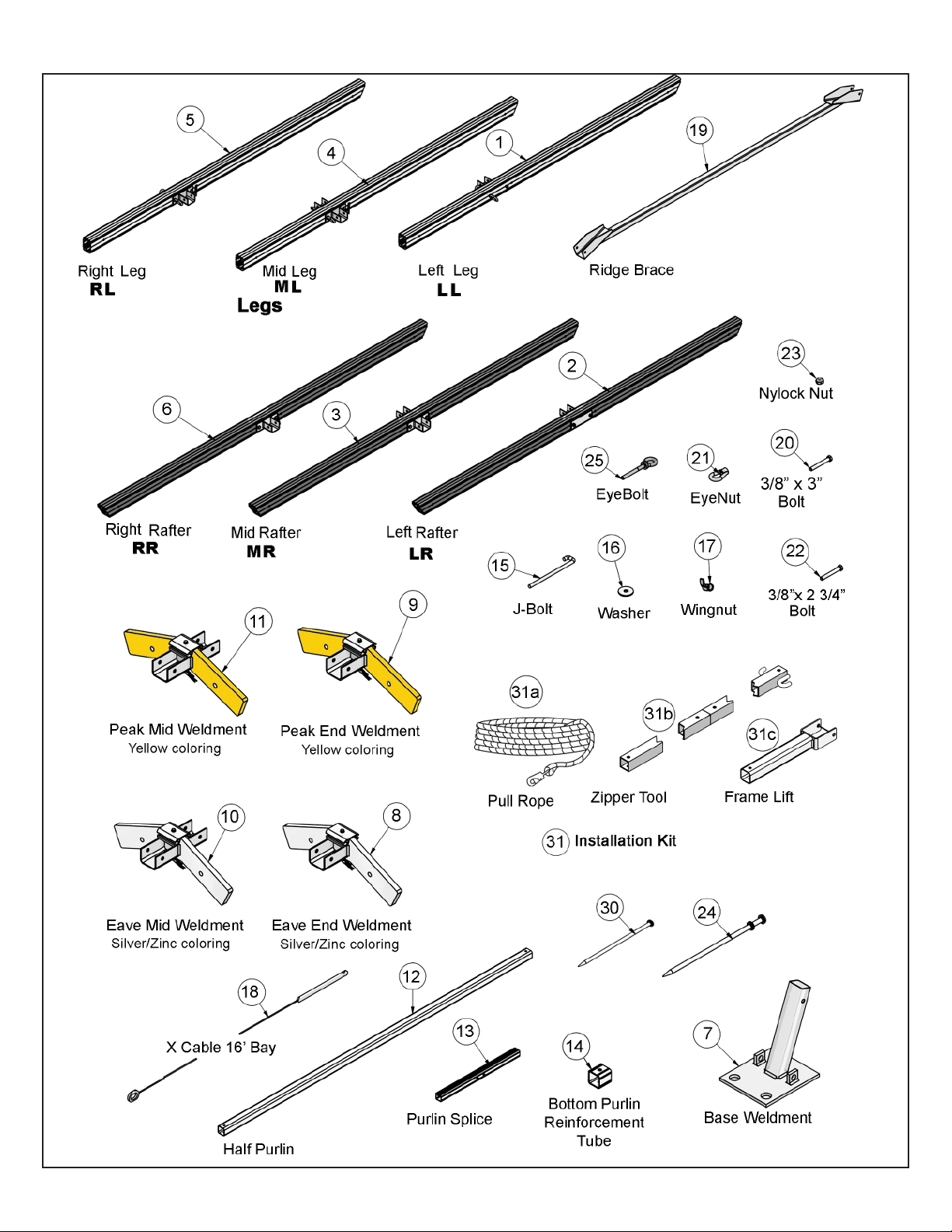
LES Component Illustrations
4
Page 5

LES INSTALLATION SAFETY GUIDELINES
Please read through this assembly manual completely before beginning your installation. Be sure the proper equipment,
crew and safety precautions are in place. We hope that you enjoy the design features of the Vehicle Maintenance Shelter
each time the unit is installed.
1. Be aware to avoid contact of frame sections with any overhead power lines near the site.
2. When anchoring the structure, avoid all underground power lines and gas lines or other utility easements.
3. When moving frame sections by hand, use proper lifting techniques to protect the back, and avoid pinching
fingers while making hardware connections.
4. Be sure all workers are cautious and attentive to the falling paths of frame sections being raised or lowered.
5. Keep site clear of debris to avoid tripping, especially while carrying frame parts or bundles of fabric.
6. Do not drag bundles of fabric on concrete, asphalt, or ground as this can cause damage to the fabric from
abrasion through the bag.
7. Do not climb onto the fabric “roof” of the structure. When necessary, work safely from a ladder of
appropriate size.
8. When standing or lowering frame sections use a smooth motion.
9. Before installing fabric, be sure the frame is safely staked at baseplates and that X-cabling is in place.
10. The installation method described here requires coordination of tasks between workers. A safe installation is
dependent on that coordination. Work cooperatively as a team.
Note: This installation is for the standard 2-mid bay Base Unit unless noted otherwise.
Note: For installation of frames with extension kits, look for notes inside these outlined boxes for special instructions.
STEP 1
Assemble 18 purlins from two purlin halves (2”x2” aluminum tubes about 8’ long) and a purlin splice (Aluminum part 2’ long
with snap buttons in the center.) See Figure 1.
Note: On 8’ Extension kits - only (1) half purlin is required, and no purlin splice.
Figure 1
5
Page 6

STEP 2 - Top Frame Assembly
• Lay out parts as shown. See Figure 2.
• Peak weldments have yellow/orange color, eave weldments are silver/zinc colored.
• Rafters have angled cuts on both ends. The end with th label assembles to the peak. (See Ridge Detail on Figure 2).
The end with no label assembles to the eave.
• Assemble the (3) Top Arches consisting of peak weldments with the corresponding rafters, eave weldments and ridge
braces
• Ensure that the End Arches are comprised of end weldments and end rafters. (Brackets on one side only.) Use the pins to
secure the joints.
• Connect the (3) arches with 10 purlins using pins adjacent to the brackets.
• Pin the two peak covers on both end peaks as shown below.
Important: For ease of installation, note that labels are always located on the upper ends of frame members.
Label at upper
ends of rafters
Figure 2
Note: For installation of frames with extension kits, lay out
each extension’s parts as shown in these diagrams.
6
Page 7

STEP 3 - Add Legs to one Side. See Figure 3.
Figure 3a
• Lay out the parts as shown in Figure 3a. Three (3) legs with baseplates and two (2) purlins.
• The leg has an angled cut on both ends. The labeled end goes toward the eave weldments.
• Insert the base plate weldments into the bottom of the legs and secure as shown in Figure 3b.
• Lift the top frame using the eave purlins and insert the leg onto the eave weldments. Secure with pin.
• Connect the legs together with 2 purlins. This is easiest if the purlin is pinned to the mid leg first before the end
leg is moved into alignment and pinned.
Only the16’-0” Bay has eye
nuts for cross cables.
Figure 3b Parts List
ITEM
20
3/8” x 3” Bolt
22
3/8” x 2 3/4” Bolt
21
Eye Nut
23
Nylock Nut
7
Base Plate Weldment
5
Right Leg
4
Mid Leg
1
Left Leg
Description
Right Leg w/
bolt and eyenut.
Mid Leg w/ eyebolt and eyenut.
Left Leg w/ bolt
and nut.
Note: On 16’ Extension Kits, substitute
the 3” Bolt (Item 20) with EyeBolt (Item
25) because eyes will be necessary on
16’ bays for connection of cross cables.
Figure 3b
7
Page 8

Frame Lift Assembly
31
Figure 4a
• Ensure sufficient personnel are on hand to lift the side (4 minimum, 3 lifting, 1 placing legs.)
STEP 4 - Add Legs to the other Side. See Figure 4b.
• Lay out the parts as the previous step. Secure the base plates to the legs with the appropriate hardware.
• Assemble the Frame lift as shown in Figure 4a.
• Secure the frame lifts to the eave purlin on the upper leg with the shock cord. The shock cord should be next to the leg
and the half purlin lying more or less under the purlin. See Figure 4b.
Note: For installation of frames with 8’ extension kits, (1) more person and (1) more frame lift assemby is required for each bay.
For installation of frames with 16’ extension kits, (2) more persons
and (2) more frame lift assemblies are required for each bay.
8
Figure 4b Parts List
ITEM
12/13
Purlin
31
Frame Lift Assembly
7
Base Plate Weldment
5
Right Leg
4
Mid Leg
1
Left Leg
Description
Figure 4b
Page 9

STEP 5 - Position and stake the base
plates.
• Position one end base plate 21’-9” from the other
end base plate. Measurement is from outside edge
of plate to outside edge of plate. See figure 5a.
• Then measure from this base plate diagonally to
the opposite base plate. Measurement should be
31’-2” from inside corner to inside corner. See fig-
ure 5a.
• Lightly stake the plates in position.
• Position the other end base plate 25’-10” from its
corresponding mate and lightly stake in place.
• Align the mid base plate between the two ends
but do not stake in place. Stake only after
ground bars and J bolts are inserted into mids
and base plates. (See Steps 9 to 10)
• Check and adjust until the diagonal measure-
ments are equal.
Note: For installation of frames with extension kits, use figures 6a and 6b for measurements.
LES Standard Base Frame
Figure 5a
Aligned Base Plates
LES - 8’ Extension Kit
Figure 6a
Aligned Base Plates
LES - 16’ Extension Kit
Figure 6b
9
Page 10

STEP 6 - Attach X Cables.
• Hook the cables into position as shown. Note the
turnbuckles are at the bottom for ease of access
and adjustment. See figure 6.
• Tension the cables to square the frame. Use a
level if possible to check the squareness of the
frame. If no level is available, the gap in the turnbuckles should be approximately equal.
Kedar for sliding fabric
into frame channel.
Turnbuckles are
toward the Base
Plates.
Figure 7a
STEP 7 - Pull first fabric mid panel into place.
• Throw the snap ends of the two (2) pull ropes from the installa-
tion kit over the top of frame. See Figure 7b.
• CAUTION: Be certain area is clear so as not to strike any-
one while throwing the pull ropes over the top.
• Lay the mid fabric next to the bottom of the legs. Mid should
be loosely stacked to permit feeding into the slots near the top
of the lower legs.
• Snap the pull ropes onto the rings of the mid.
• Insert kedar ends of mids into slots. See Figure 7a.
• Two (2) to four (4) persons pull the fabric over the top of the
frame down to the bottom of the far leg, while two (2) persons
guide the edges into the slots. See Figure 7c.
• Disconnect the pull lines.
• CAUTION: Be certain at all times that fabric is not caught
on any part of the frame to prevent damage to the fabric.
Figure 6
Snap ends of
Pull ropes.
Figure 7b
• Insert the trailing kedar edges into the slots and work back
down to the bottom of the near leg.
• Remove the half-purlins and splices from the frame lifts and
attach the remaining half purlins to create four (4) purlins which
will now be used as ground bars to secure and tension the lower
edges of the mid panels.
• Loosen and release the bottom of the X-Cables to permit
installation of the ground bars.
• Insert a ground bar into the pocket at the bottom of each side
of the mid panel.
10
Slot in channel
Figure 7c
Page 11

Washer &
Wing Nut
J-Bolt
Ground bar with
reinforcement tube.
Ground bar inserted
into mid pocket.
Figure 7d
• Insert a reinforcement tube into each end of the ground bar and align holes. Hook J-Bolt through hole in vertical plate on
base plate and lower ground bar onto J-Bolt. Secure with washer and wing nut. Wing Nuts are used to tension and position
the fabric. See figures 7d through 7f.
• Re-attach the bottom of the X-Cables and re-tension.
Figure 7e
Figure 7f
STEP 8 - Pull second mid panel into place.
• Proceed as with the first mid.
• Stake mid base plates.
STEP 9 - Pull first gable end
into place
• Be certain that the zippers of the
Gable End are unzipped for ease of
installation.
• Lay out the gable end panel at bottom of one of the end legs. White
side of gable end to inside of tent.
See figures 9a and 9b.
• Insert end of kedar into slotted
opening of top/outer channel of lower
leg. Push the inserted kedar up the
channel of the leg as far as possible (to about the corner). The zipper tool will be required to push the kedar up past the corner.
Pull rope
Pull rope snapped
onto ring of Gable end.
Slotted
Opening
Zipper
Tool
Gable end
Figure 9a
Bottom of
Gable End
Slotted
Opening
Kedar of
Gable end.
Figure 9b
• Once the kedar is past the corner, the zipper tool may be used to guide the pull rope while another person pulls on the rope
until the gable end is pulled past the peak and eave corner. Continue pulling the gable end until the bottom of the kedar reaches the far base plate and the gable end is centered in the end. See figure 9a.
• Disconnect the pull rope.
• Go back to the slot where you started the gable end installation, and stuff the remaining kedar into the lower channel below
the slotted opening down to the base plate.
• You may use the zipper tool to zip the zippers.
• Gable end may be staked with stakes provided.
Your Light Expeditionary Shelter (LES) is now ready for use.
11
Page 12

EVANSVILLE, INDIANA
PHONE NUMBER
812· 867· 2421
FAX NUMBER
812· 867· 0547
Anchor products are of superior design and operate best within the parameters of these instructions. It is imperative
that the instructions be carefully read and COMPLETELY FOLLOWED. Please read installation instructions before the
installation or removal of this product. Installation instructions are available online at www.anchorinc.com or by calling
1-800-544-4445.
CAUTION:
1. For each installation, the installer is solely responsible for evaluating the site and the proper securing method
determined. Some soils require different staking or securing than that provided with the tent. Due to this variety of
soil conditions, these are the manufacturer’s suggested sequence of installation procedures. Anchor’s responsibility
is limited to the manufacture of the tent parts and materials. We are not responsible for methods that installers may
choose to erect and secure the tent to the ground.
2. The number of stakes suggested in the installation instructions does not necessarily meet all or any relevant codes
on the site of the tent installation. The number of stakes suggested will, in many cases, keep the tent erected,
however, due to various soil conditions; these stakes will be insuf¿ cient to keep the tent secure in high winds.
It is the tent installer’s responsibility, not the manufacturer, to determine the appropriate number of stakes to meet
the necessary wind loads on the site. Regardless of the number of stakes we suggest, we make no representation
or warranty as to whether this speci¿ c number of stakes will meet the local tent code. Anchor does not, nor can
it make any suggestions, representation, or warranties about the adequate staking required at each speci¿ c
installation site. Staking information provided in the installation instructions is not a suggestion about what is
necessary to meet a site-speci¿ c load.
For additional assistance, consult: “The IFAI Procedural Handbook For the Safe Installation and
Maintenance of Tentage” and the IFAI Pocket Guide “Pullout Capacity of Tent Stakes”, both available from
the IFAI Tent Rental Division or on our website.
3. Inasmuch as the weather is unpredictable, good judgment and common sense must be incorporated within
installation guidelines. It is the responsibility of the tent installer/maintainer to determine the severity of the weather,
proper time and method of installation and/or erection and disassembly. Note: We recommend that snow and
ice be removed from the tent surface as soon as possible because accumulation will damage the tent
or fabric structure. Please consult with our Engineering Department about the maximum loads for each
product.
This product has been manufactured for use as a temporary structure. For the safety of all occupants, evacuation
is recommended if threatening weather occurs, or if there is any doubt concerning the safe use of this product.
4. Proper safety equipment should be used at all times to insure a safe installation and take down. We suggest a
careful evaluation be made to determine safety equipment needed, such as hard hats, steel-toe shoes, safety
glasses and other as required. It is our desire that all installations are safe. Please be aware of hidden dangers
both underground, i.e., gas lines, water lines, electrical lines, etc. and above the tent such as power lines and
telephone lines.
5. Anchor stands behind its products in accordance with its standard Terms and Conditions of sale. A copy of our
Terms and Conditions of Sale can be obtained by contacting Anchor at the telephone number and/or address on
this document.
28.2 04-29-08
 Loading...