

Page 1
ASSEMBLY INSTRUCTIONS
40’ x 40’ CERTIFIED ANCHOR
BANDSHELL
Please read all assembly/installation instructions before the installation or removal of this product.
SALES OFFICES:
1100 BURCH DRIVE
PO BOX 3477
EVANSVILLE, IN 47733
USA
PHONE: 812-867-2421
FAX: 812-867-0547
1-800-544-4445
EMAIL: tents@anchorinc.com
www.anchorinc.com
PRODUCTION FACILITIES:
EVANSVILLE, IN
Quality, Craftsmanship and Service since 1892
BS4040 0612EC4531
Page 2

40’ x 40’ BANDSHELL PACKING LIST
DESCRIPTION:
Three (3) sections of bandshell fabric in canvas bags. Marked FRONT, MIDDLE, And REAR.
30” Steel Stake (for Base plates)
Front Pole, 32’-4” long aluminum
Rear Pole, 28’-4” long aluminum
Pole Base Plate with Bolt & Nut
1’-9 1/4” Cable (3/8”) with 1’-0” turnbuckle and shackle Guy (Point A)
1’-3 3/4” Cable (3/8”) with 1’-0” turnbuckle and shackle Guy (Point B)
2’-2 1/2” Cable (3/8”) with 1’-0” turnbuckle and shackle Guy (Point D)
1’-5 3/4” Cable (3/8”) with 1’-0” turnbuckle and shackle Guy (Point E & F)
2’-3 1/2” Cable (3/8”) with 1’-0” turnbuckle and shackle Guy (Point G)
28’-11 3/8” (3/8”) Cable with 1’-0” turnbuckle and shackle Guy (Point I)
(1) 7/8” Shackle, (2) Pear Rings, (4) 1’-0” Turnbuckles for Double Guy (Point C)
(1) 7/8” Shackle, (2) 12’-4” Cables (5/8”, (4) 1’-0” Turnbuckles for Double Guy (Point H)
Quantity
3
8
2
2
4
2
2
2
4
2
2
2
2
CAUTION
DESCRIPTION:
100’ Tape Measure
Pole Stand (Tripod Type)
Pull Rope Assembly
Support Guy
36’-0” Take-up Double Block & Tackle
20’-0” Pole
Drop Cloths (approx. 40’ x 50’)
The installation of the Anchor Bandshell should be performed/supervised by knowledgable tent
installers with a clear understanding of safety issues as well as the methods of anchoring.
The installer/owner should read the assembly instructions completely prior to any installation.
Special attention should be given to anchoring! It is the responsibility of the installer/owner to
assure proper anchoring at all points and that the anchoring system meet the load requirements
defined on the blue print information included (see page 9). Additionally, blue prints are available for all “Certified” Bandshell orders.
TOOLS REQUIRED
(NOT PROVIDED WITH BANDSHELL)
Quantity
2
4
2
2
2
4
3
Drop Cloths (approx. 15’ x 40’)
Stake or Anchor Installation Tools (Manual or Power Drive Anchor Installers)
3
As Required
NOTE: Tools may be purchased from Anchor Industries Inc. or supplied by installer.
1
Page 3
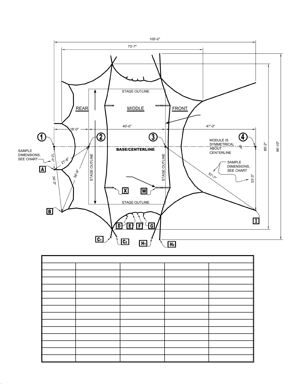
40’ x 40’ BANDSHELL
Pole & Anchor Layout
60’-0”
TYPICAL STAGE
POSITION
BASE OF CENTER
POLE
DIMENSION CHART FOR POLE & STAKE LAYOUT
STAKING PT.
A
B
C
1
C
2
D
E
F
G
H
1
H
2
I
X*
W*
*POLE BASE PLATE POSITIONS.
DIST. FROM 1 DIST. FROM 2 DIST. FROM 3 DIST. FROM 4
12’-0” 21’-8” - -
34’-3” 36’-9” - -
- 48’-8” 55’-2” -
- 48’-11” 53’-3” -
- 41’-6” 41’-3” -
- 42’-0” 39’-1” -
- 43’-5” 38’-0” -
- 46’-1” 38’-0” -
- 57’-11” 48’-1” -
- 60’-11” 48’-6” -
- - 57’-7” 33’-3”
-
-
25’-0” 34’-5”
41’-0
”
21’-11”
-
-
2
Page 4
40’ x 40’ BANDSHELL ASSEMBLY INSTRUCTIONS
MINIMUM OF EIGHT WORKERS ARE REQUIRED TO ASSEMBLE THE BANDSHELL.
1.
THE FIRST STEP IS TO LOCATE THE STAKE AND BASE PLATE POINTS, USING THE DIMENSION
CHART ON PAGE 2.
YOU WILL NEED TWO 100’ TAPE LINES AND HAVE SEVERAL MARKERS AVAILABLE TO
MARK THE ANCHOR POINTS. DO NOT USE MARKERS WITH SHARP EDGES. THE
FABRIC WILL REST ON SOME MARKERS BEFORE RAISING. A CAN OF QUICK-DRY SPRAY
PAINT WILL DO, IF PERMANENT MARKING OF SITE IS ALLOWED.
DETERMINE WHERE THE CENTER AND FRONT OF THE STAGE IS TO BE. POSITION THE
BASE/CENTER LINE SO THAT IT SPLITS THE STAGE IN HALF. LOCATE THE REFERENCE
POINTS 1 THRU 4 AND MARK EACH. POINTS 2 & 3 ARE AT THE FRONT AND REAR EDGE OF A
40’-0” DEEP STAGE.
NOW LOCATE AND MARK EACH POINT BY HOLDING THE END OF EACH TAPE AT THE
CORRECT REFERENCE POINT AND MATCH THE CHART DIMENSIONS ON EACH TAPE. NOTE
THAT THE POINTS ARE SYMMETRICAL ABOUT THE CENTER LINE.
WE RECOMMEND THAT YOU MARK YOUR TAPE LINES FOR EACH POINT TO DECREASE
LAYOUT TIME AND CHANCES OF ERRORS.
INSTALL STAKES OR ANCHORING DEVICES AT EACH POINT AS SHOWN ON LAYOUT. THEN,
2.
STAKE THE FOUR BASEPLATES AT POINTS X & W WITH THE HINGE BOLT PERPENDICULAR
TO THE CENTER LINE. WHEN INSTALLING AUGER STAKES, INSTALLER SHOULD BE FAMILIAR
WITH HOW TO PROPERLY SECURE TO GROUND AS WELL AS WITH MECHANICAL EQUIPMENT
AVAILABLE TO ASSIST IN THIS TASK. INSTALLATION DIRECTIONS CAN BE OBTAINED FROM
THE SUPPLIER OF AUGERS. EACH GUY CABLE PROVIDED WILL TERMINATE WITH A JAW/EYE
TURNBUCKLE WHICH MUST ADAPT TO THE ANCHORING SYSTEM YOU HAVE CHOSEN.
CAUTION: IT IS THE INSTALLER/OWNERS’ RESPONSIBILITY TO EVALUATE AND APPROVE
THAT ALL ANCHORING DEVICES MEET DEFINED LOADING. A PULL TEST OR ANALYSIS
SHOULD BE DONE ON THE STAKING OR ANCHORING SYSTEM TO ASSURE THE LOADING
INFORMATION INDICATED ON
THE “PULLOUT LOAD” PRINT
IS ADEQUATELY MET.
ASSEMBLE POLES. EACH
3.
POLE SECTION IS MARKED
WITH A LETTER. MATCH
SECTIONS WITH THE
SAME LETTER AND BOLT
TOGETHER.
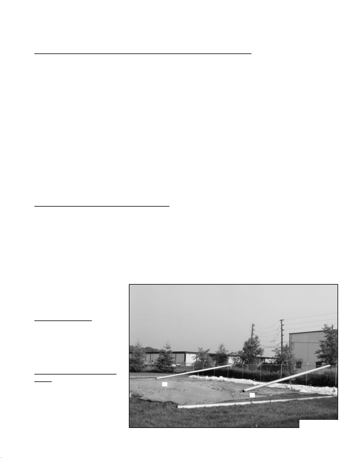
4.
LAY DROP CLOTHS OVER
AREA TO PROTECT
BANDSHELL TOP
X
X
Photo 1
3
Page 5

UNFOLD REAR SECTION TO THE
5.
REAR OF POINTS X WITH LOOP
SIDE TOWARD THE FRONT OF THE
STAGE. WHEN COMPLETELY LAID
FLAT, FOLD THE LOOP SIDE BACK
ALMOST TO POINT A.
PLACE POLE STAND
6.
APPROXIMATELY 15’-0” DIRECTLY
BEHIND BASE PLATES AT BOTH
POINT X’S. MOUNT THE 28’-4”
REAR POLES IN BASE PLATE WITH
THE TOP TOWARD THE REAR AND
SITTING IN THE POLE STAND. THE
TOP OF THE POLE SHOULD BE
APPROXIMATELY 5’-0” OFF THE
GROUND.
(PHOTOS #1, & 2).
LAY DROP CLOTHS OVER POLES
7.
AND AROUND AREA FOR MIDDLE
SECTION PROTECTION.
BasePlate
Photo 2
8.
UNFOLD MIDDLE SECTION
BETWEEN BASE PLATES AT
POINTS X AND W, WITH THE LOOP
SIDE TOWARD THE FRONT OF
THE STAGE. WHEN COMPLETELY
LAID OUT, PLACE THE SPOKE
RINGS ON THE HOLE SIDE OF
THE MIDDLE SECTION OVER THE
POLE PINS, WHILE THREADING
THE CABLES THROUGH THE
RING. THEN, DO THE SAME WITH
THE SPOKE RINGS ON THE REAR
SECTION, PLACING THEM ON TOP
OF THE FIRST RINGS. FOLD LOOP
SIDE OF MIDDLE SECTION BACK
APPROXIMATELY 10’-0” PAST
POINTS X.
( PHOTO #3).
Photo 3
W
W
Photo 4
4
Page 6

9.
PLACE POLE STAND
APPROXIMATELY 15’0” DIRECTLY BEHIND
BASE PLATES AT BOTH
POINTS W. MOUNT THE
32’-0” FRONT POLES
IN BASE PLATE WITH
THE TOP TOWARD THE
REAR AND SITTING
IN THE POLE STAND.
THE TOP OF THE
POLE SHOULD BE
APPROXIMATELY 5’-0”
OFF THE GROUND.
(PHOTO #2).
LAY DROP CLOTHS
10.
OVER POLES AND
AROUND AREA FOR
FRONT SECTION
PROTECTION.
Photo 5
11.
UNFOLD FRONT
SECTION IN FRONT
OF BASE PLATES
AT POINTS W & W
WITH HOLE SIDE
TOWARD THE MIDDLE
SECTION. WHEN
COMPLETELY LAID
OUT, PLACE THE
TOP-HOLE RINGS ON
HOLE SIDE OF FRONT
SECTION OVER THE
POLE PINS, WHILE
THREADING THE
CABLES THROUGH
THE RING. THEN, DO
THE SAME WITH THE
TOP RINGS ON THE
LOOP SIDE OF THE
MIDDLE SECTION,
PLACING THEM ON
TOP OF THE FIRST RINGS. ( PHOTO #4).
Long loop
Photo 6
LACE ALL THREE SECTIONS TOGETHER. START AT TOP RING ON THE RIDGE SIDE WITH NO LONG
12.
LOOP. LACE ACROSS THE RIDGE AND TIE OFF WITH THE LONG LOOP. THEN, LACE DOWN EACH
SLOPE AND TIE OFF AT EAVE WITH LONG LOOP. BE SURE THE LOOP SIDE WEB IS BETWEEN THE
GROMMET FLAP AND THE HOLE SIDE WEB. LACING REQUIRES WALKING ON THE BANDSHELL
TOP AND IT IS ADVISABLE TO REMOVE YOUR SHOES. (PHOTOS #5, 6 & 7).
5
Page 7

Photo 7
Long loop
13.
ATTACH FLAP SNAPS TO ROPES THAT ARE THROUGH D-RINGS ON TOP. SLOPE FLAPS ARE
SEPARATE FLAPS AND ARE TO BE SNAPPED TO ROPES ON BOTH SIDES. ONE SNAP SHOULD BE
ATTACHED TO THE ROPE BETWEEN EACH D-RING. (PHOTO #8).
Photo 8
14.
ATTACH GUY CABLES AT ALL POINTS (A THRU I). (SEE TABLE OF CABLES BELOW). CONNECT
THE END OPPOSITE THE TURNBUCKLE TO THE EAVE RING ON BANDSHELL.
NOTE: AT POINTS C & H, BE SURE THE LOOP SIDE PEAR SHAPED RING IS ON TOP OF THE HOLE
SIDE PEAR SHAPED RING; AND THAT THE PEAR SHAPED RINGS ARE TURNED, SO THE SHACKLE
IS PULLING ON THE SMALLER ENDS OF THE RINGS.
15.
ASSEMBLE RIGGING
A. SNAP ON SUPPORT GUY TO THE CABLES AT THE TOP OF EACH FRONT POLE AND LOOSELY
TIE OFF THE OTHER END TO POINT H2.
B. ATTACH ONE PULL ROPE TO THE CABLES AT THE TOP OF EACH FRONT POLE. CONNECT
ONE DOUBLE BLOCK & TACKLE AT BOTH POINT I’S. WITH THE BLOCKS FULLY EXTENDED, TIE
THE PULL ROPES TO THE BLOCKS. LOOSELY TIE OFF THE BLOCK & TACKLES.
C. LASH TWO SETS (2) 20’-0” POLES TOGETHER AT THE TOP AND SECURELY ATTACH ONE SET
TO RINGS ON EACH PULL ROPE. SET POLES UP, FORMING AN A-FRAME CANTILEVER TO LIFT
FRONT POLES (BOTTOM OF A-FRAME SHOULD BE APPROXIMATELY 12’ WIDE). (PHOTOS #9,
10, 11 & 12).
Location
Point
A
B
1’-9 1/4” Total Guy Length - (3/8”) Cable with (1) 1/2” x 1’-0” turnbuckle and (1) shackle
1’-3 3/4” Total Guy Length - (3/8”) Cable with (1) 1/2” x 1’-0” turnbuckle and (1) shackle
TABLE OF CABLES
Quantity
2
2
C1 & C2
D
E & F
G
H1 & H2
I
(1) 7/8” Shackle, (2) Pear Rings, (4) 3/4” x 1’-0” Turnbuckles for Double Guy
2’-2 1/2” Total Guy Length - (3/8”) Cable with (1) 1/2” x 1’-0” turnbuckle and (1) shackle
1’-5 3/4” Total Guy Length - (3/8”) Cable with (1) 1/2” x 1’-0” turnbuckle and (1) shackle
2’-3 1/2” Total Guy Length - (3/8”) Cable with (1) 1/2” x 1’-0” turnbuckle and (1) shackle
(1) 7/8” Shackle, (2) 12’-4” (5/8”) Cables , (4) 3/4” x 1’-0” Turnbuckles for Double Guy
28’-11 3/8” Total Guy Length - (3/8”) Cable with 1/2” x 1’-0” turnbuckle and (1) shackle
2
2
4
2
2
2
6
Page 8

BE SURE THE CABLE GUYS AT POINTS A, B AND C
16.
(BOTH HALVES - 6 PLACES) HAVE BEEN SECURED
TO ANCHORS. NOW, START PULLING ON ONE
OF THE BLOCK & TACKLES, RAISING THE FRONT
POLE UNTIL THE OPPOSITE FRONT POLE STARTS
TO MOVE. TIE OFF THE BLOCK & TACKLE AND DO
THE SAME WITH THE OTHER BLOCK & TACKLE,
SWITCHING BACK AND FORTH, WATCHING THE
REAR POLES ALSO, UNTIL THE FRONT POLES
FALL SLIGHTLY FORWARD. TIE OFF GUYS AT
POINTS I, REMOVE BLOCK & TACKLES AND
A-FRAME POLES. (PHOTOS #10, 11 & 12).
IF THERE ARE ENOUGH WORKERS, BOTH BLOCK
& TACKLES CAN BE PULLED AT THE SAME TIME.
SECURE AND TENSION ALL GUY CABLES,
17.
USE THE FOLLOWING ORDER TO PROPERLY
SHAPE THE TOP (ADJUSTING TURNBUCKLES AS
REQUIRED).
A. HOOK COME-ALONGS FROM POINTS H
ON TOP TO POINT H1 & H2 ANCHORS (USE STUB
ROPES IF NEEDED) ON EACH SIDE OF TENT (ALL
4 COME-ALONGS REQUIRED.) THEN, TENSION
EACH EQUALLY UNTIL THE FRONT POLES ARE
VERTICAL WHEN LOOKING FROM THE FRONT
AND POINT H IS ABOUT 11’-0” FROM THE GROUND
(BE SURE THE SUPPORT GUYS DO NOT BECOME
TIGHT AND HOLD THE POLES APART). SECURE
GUY CABLES AND REMOVE COME-ALONGS.
Photo 9
B. REPEAT STEP A AT POINTS C TO C1 & C2
WITH REAR POLES TO BE VERTICAL AND POINT C
ABOUT 3’-0” FROM THE GROUND.
C. TIGHTEN GUYS AT POINTS
A & B UNTIL REAR SECTION IS
TENSIONED UNIFORMLY AND
POINTS ARE ABOUT 2’-3” AND 1’-6”
RESPECTIVELY FROM THE GROUND.
D. TIGHTEN CABLES AT
POINTS I UNTIL FRONT SECTION
IS TENSIONED UNIFORMLY AND
POINT I IS ABOUT 12’-0” FROM THE
GROUND.
E. TIGHTEN CABLES AT POINTS
D, E, F, & G UNTIL POINTS ARE
ABOUT 4’-0” TO 5’-0” FROM THE
GROUND.
Photo 10
7
Page 9

NOTE:
1. TENSION TOP
SYMMETRICALLY ABOUT THE
CENTER LINE. PULL ON LIKE
POINTS ON EACH SIDE OF TENT
AT THE SAME TIME
(A & A, B & B, D & D, ETC).
2. THE POLES ARE TO
BE VERTICAL FROM THE
FRONT. THE FRONT POLES
ARE TO LEAN APPROXIMATELY
7’-5” FORWARD AND THE
REAR POLES ARE TO LEAN
APPROXIMATELY 4’-8”
BACKWARD.
18.
DOUBLE CHECK THAT ALL GUYS
AND STAKES ARE SECURE. DO
THIS AT LEAST DAILY, MORE
IN BAD WEATHER. THE GUYS
WILL TEND TO LOOSEN DUE TO
FABRIC STRETCH, WIND AND
STAKE MOVEMENT.
Photo 11
Photo 12
19.
LOOSELY TIE PULL ROPE TO
POINTS H1 OR H2 AND LEAVE
SUPPORT GUY IN PLACE.
THEY WILL BE USED FOR
DISASSEMBLY.
SEE PHOTOS OF COMPLETED
ASSEMBLY: PHOTOS #13, 14
& 15)
Photo 13
8
Page 10

40’ x 40’ BANDSHELL LOAD REQUIREMENTS
FOR ANCHORING SYSTEM
Photo 14
9
Page 11

DISASSEMBLY INSTRUCTIONS
Photo 15
1. DISASSEMBLY IS THE REVERSE OF ASSEMBLY, EXCEPT AS FOLLOWS:
A. BE SURE A-FRAME POLES ARE SECURELY FASTENED TO RING ON PULL ROPE.
THEY WILL BE LIFTED UP DURING THE FIRST STEPS AND MAY COME LOOSE.
B. THE BLOCK & TACKLE SHOULD BE PUT IN PLACE WITH A MINIMUM OF TAKE-UP.
C. CHECK SUPPORT ROPE, IT SHOULD NOT BE VERY TIGHT.
D. TO START THE POLES DOWN, RELEASE THE GUYS AT POINT I AND PUSH THE
FRONT POLES BACK (BE SURE THE BLOCK & TACKLE IS TIED OFF).
E. BE SURE MATERIAL IS NOT CAUGHT AS YOU LET THE POLES DOWN ONTO
STANDS.
2. CARE AND STORAGE:
A. ALWAYS MAKE ABSOLUTELY SURE FABRIC IS DRY BEFORE STORING.
B. STORE IN PROVIDED SACKS IN A COOL, DRY AREA - AWAY FROM RODENTS.
RODENT PROTECTION MAY BE NECESSARY IF THEY ARE PLENTIFUL. KEEP OFF
FLOOR.
C. CLEAN FABRIC WITH MILD LAUNDRY DETERGENT AND A SOFT BRISTLED BRUSH.
A HIGH PRESSURE SPRAYER MAY BE USED, BUT KEEP THE NOZZLE 18” AWAY
FROM FABRIC. DO NOT USE STEAM CLEANERS.
D. SAND AND PAINT THE STEEL BASE PLATES, STAKES AND TOP OF POLES BEFORE
STORING TO ELIMINATE FUTURE RUSTING.
E. FOR SAFE BANDSHELL PERFORMANCE, CONDUCT REGULAR INSPECTION OF ALL
CABLES, WEBS, HARDWARE AND STRUCTURAL COMPONENTS. REPLACE
COMPONENTS IF THEY ARE WORN OR QUESTIONABLE.
10
Page 12

EVANSVILLE, INDIANA
PHONE NUMBER
812· 867· 2421
FAX NUMBER
812· 867· 0547
Anchor products are of superior design and operate best within the parameters of these instructions. It is imperative
that the instructions be carefully read and COMPLETELY FOLLOWED. Please read installation instructions before the
installation or removal of this product. Installation instructions are available online at www.anchorinc.com or by calling
1-800-544-4445.
CAUTION:
1. For each installation, the installer is solely responsible for evaluating the site and the proper securing method
determined. Some soils require different staking or securing than that provided with the tent. Due to this variety of
soil conditions, these are the manufacturer’s suggested sequence of installation procedures. Anchor’s responsibility
is limited to the manufacture of the tent parts and materials. We are not responsible for methods that installers may
choose to erect and secure the tent to the ground.
2. The number of stakes suggested in the installation instructions do not necessarily meet all or any relevant codes
on the site of the tent installation. The number of stakes suggested will, in many cases, keep the tent erected,
however, due to various soil conditions; these stakes will be insuf¿ cient to keep the tent secure in high winds.
It is the tent installer’s responsibility, not the manufacturer, to determine the appropriate number of stakes to meet
the necessary wind loads on the site. Regardless of the number of stakes we suggest, we make no representation
or warranty as to whether this speci¿ c number of stakes will meet the local tent code. Anchor does not, nor can
it make any suggestions, representation, or warranties about the adequate staking required at each speci¿ c
installation site. Staking information provided in the installation instructions is not a suggestion about what is
necessary to meet a site-speci¿ c load.
For additional important information, consult: “The IFAI Procedural Handbook For the Safe Installation and
Maintenance of Tentage” and the IFAI Pocket Guide “Pullout Capacity of Tent Stakes”, both available from
the IFAI Tent Rental Division or on our website.
3. Inasmuch as the weather is unpredictable, good judgment and common sense must be incorporated within
installation guidelines. It is the responsibility of the tent installer/maintainer to determine the severity of the weather,
proper time and method of installation and/or erection and disassembly. Note: We recommend that snow and
ice be removed from the tent surface as soon as possible because accumulation will damage the tent
or fabric structure. Please consult with our Engineering Department about the maximum loads for each
product.
This product has been manufactured for use as a temporary structure. For the safety of all occupants, evacuation
is recommended if threatening weather occurs, or if there is any doubt concerning the safe use of this product.
4. Proper safety equipment should be used at all times to insure a safe installation and take down. We suggest a
careful evaluation be made to determine safety equipment needed, such as hard hats, steel-toe shoes, safety
glasses and other as required. It is our desire that all installations are safe. Please be aware of hidden dangers
both underground, i.e., gas lines, water lines, electrical lines, etc. and above the tent such as power lines and
telephone lines.
5. Anchor stands behind its products in accordance with its standard Terms and Conditions of sale. A copy of our
Terms and Conditions of Sale can be obtained by contacting Anchor at the telephone number and/or address on
this document.
28.2 03-04-09
 Loading...