

Page 1
Assistive Listening Owners Manual
A Message from the President
Congratulations on purchasing an Anchor Audio system, the choice of thousands of
satisfied customers including the White House, prestigious universities, school districts
nationwide, police and fire departments, and all branches of the U.S. Military. Our
products are made of the finest materials and built with pride in the U.S.
We’ve incorporated the latest technology into your sound system yet kept it simple to
use. Just take a few minutes to review this manual to ensure the maximum enjoyment
of your Anchor system. Or, you can view a demonstration video complete with a trouble
shooting section at www.anchoraudio.com.
Feel free to call our friendly customer support staff at 1-800-ANCHOR1
with any questions. We love to hear from our customers.
Janet Jacobs, President
on behalf of all Anchor employees
CONTENTS
GETTING STARTED .................................................................................................................. 1
QUICK SETUP ......................................................................................................................... 2
TRANSMITTER FEATURES/BELTPACK RECEIVER FEATURES ....................................................... 3
CHANGING FREQUENCIES/SYNCING BELTPACKS .......................................................................4
IMPORTANT SAFETY INSTRUCTIONS ........................................................................................ 5
HAVING TROUBLE WITH YOUR SYSTEM?/TECHNICAL SPECIFICATIONS/ ANCHOR WARRANTY...... 6
TWO YEAR WARRANTY
GETTING STARTED
Please check your new unit carefully for any
damage which may have occurred during shipment.
Each Anchor product is carefully inspected at the
factory and packed in specially designed boxes for
safe transport.
Notify the freight carrier immediately of any damage
to the shipping box or product. Repack the unit
in the original box and wait for inspection by the
carrier’s claim agent. Notify your dealer of the
pending freight claim.
NOTE: All damage claims must be made with freight carrier!
RETURNING SYSTEMS FOR SERVICE
OR REPAIR
For service or repair, please contact the dealer
you purchased your system from, call us at 1-800262-4671, or visit www.AnchorAudio.com, Contact
Us page. Our tech support team will issue an RA
number for warranted systems, after which, you can
ship the item(s) to Anchor for repair. All shipments
to Anchor Audio must include an RA number and
must be shipped prepaid. C.O.D. shipments and
shipments without an RA number will be refused
and returned at your expense.
IMPORTANT: Save the shipping box & packing materials,
they were specially designed to ship your unit!
100-0321-000
1
For System Setup & Operation Videos Visit Our Website: www.anchoraudio.com
Page 2
Assistive Listening Owners Manual
Diversity Wireless by Anchor Audio
Anchor Audio Assistive Listening Systems are 100 channel UHF diversity wireless systems. Diversity wireless technology utilizes two independent antennae to receive signals. The diversity feature
means the receiver will process the stronger of the two antenna signals, effectively minimizing dropouts and interference from other sources.
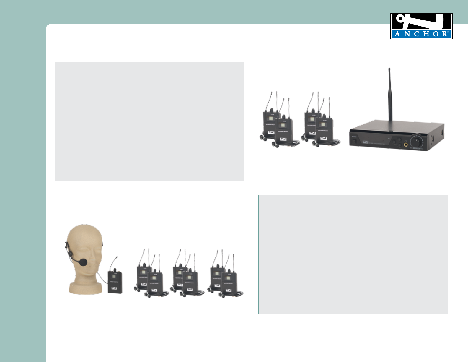
AL-9000 Assistive Listening Package
Quick System Setup Instructions – Assistive Listening Package
ALT-9000 Assistive Listening Transmitter
1. Connect provided external antenna
2. Plug in ALT-9000
3. Power on transmitter base station
4. Plug in audio source to ALT-9000 into one or both line-in
5. Adjust input gain/volume knob on back panel as needed
ALB-9000 Assistive Listening Beltpack Receiver
1. Install 2 AA 1.5V batteries in beltpack
2. Extend antennas for maximum reception
3. Plug in headphones
4. Power on ALB-9000
5. Adjust volume as needed
NOTE:
Verify both transmitter beltpack and beltpack receivers are synchronized to the same channel.
Default frequency setting is 902.00. This can be changed as needed. See Changing
transmitter frequency on page 4.
ALB-9000
Quick System Setup Instructions – Tour Guide Package
Tour-9000 Tour Guide Package
WB-9000 Assistive Listening Beltpack Transmitter
1. Install 2 AA 1.5V batteries in beltpack
2. Extend antenna for maximum reception
3. Plug in microphone element to beltpack
4. Power on WB-9000
5. Adjust volume as needed
ALB-9000 Assistive Listening Beltpack Receiver
1. Install 2 AA 1.5V batteries in beltpack
2. Extend antennas for maximum reception
3. Plug in headphones
4. Power on ALB-9000
5. Adjust volume as needed
TWO YEAR WARRANTY
ALT-9000
WB-9000
NOTE:
ALB-9000
NOTE: It is advised to set the beltpack receiver volume to its minimum. Increase volume gradually to a comfortable level.
Also, if using base station transmitter, set the input gain/volume knob to a minimum level to reduce hissing.
Verify both transmitter beltpack and beltpack receivers are synchronized to the same channel.
Default frequency setting is 902.00. This can be changed as needed. See Changing
transmitter frequency on page 4.
For System Setup & Operation Videos Visit Our Website: www.anchoraudio.com
2
Page 3

Assistive Listening Owners Manual
TWO YEAR WARRANTY
Transmitter Base Station Features
4
1
1. POWER SWITCH
Press to power on, press to power off, blue lights illuminate up when transmitter is on
2. LCD DISPLAY
The high resolution LCD display shows the group, channel frequency, antenna status,
RF level and IR set
3. IR INFRARED PORT
Sends IR signal to the receiver for frequency synchronization
4. UP BUTTON
Adjusts the frequency, channel, group, and power
5. SET BUTTON
Menu control to set group, channel, frequency, power, and IR Synch
6. DOWN BUTTON
Adjusts the frequency, channel, group, and power
7. VOLUME CONTROL
Headphone jack volume control
8. HEADPHONE JACK
Headphone output connector 1/4” jack
9. POWER SUPPLY JACK (DC12-18V / 500mA)
Power supply input jack
10. 1/4” AUDIO INPUT JACKS
Connects audio source (mixer, computer, etc.)
11. INPUT VOLUME CONTROLS
Input volume control/input gain
12. TNC ANTENNA SOCKET
High gain antenna input
2 3 5 6 8 7
FRONT
ALT-9000
11 10 10 11 9 12
BACK
Beltpack Receiver Features
1
2
5
6
4
7
3
ALB-9000 WB-9000
1. ANTENNA
1/4 wavelength wire type antenna(s). Should be
fully extended during normal operations.
2. BACKLIT LCD
Displays frequencies and battery life. Replace
batteries when symbol blinks.
3. UP BUTTON
Adjusts the frequency
4. SET BUTTON
Menu control to set the frequency
5. DOWN BUTTON
Adjusts the frequency
6. IR INFRARED PORT
Receives IR signal from transmitter base station
to synchronize frequencies. Hold the receiver with
IR port facing directly to transmitter IR port when
transmitter is in sync mode (ALB-9000 only).
ALB-9000 TOP
10 9 8
11
11
10 9 12
2
7
1
11
WB-9000 TOP
7. BATTERY COMPARTMENT
To replace batteries, slightly press the marked
positions on sides of the cover. Make sure to check
polarity of the batteries.
8. HEADPHONE AUDIO OUTPUT
3.5mm plug (ALB-9000 only)
9. VOLUME CONTROL
Turn clockwise to increase, counter-clockwise to
decrease
10. POWER SWITCH
Press to turn on, hold for 2 seconds to turn off
11. RF INDICATORS
Antenna indicator(s)
12. MIC INPUT
Mini XLR microphone element input (
WB-9000 only)
5
4
3
For System Setup & Operation Videos Visit Our Website: www.anchoraudio.com
3
Page 4

Assistive Listening Owners Manual
CHANGING TRANSMITTER AND BELTPACK FREQUENCIES
The Assistive Listening 9000 system operates on the 902-928 MHz frequency range. The default frequency is set to 902.00 MHz. If you are experiencing interference or need to change to a
different channel, follow the steps below to first select transmitter frequency, then sync beltpacks. There are 100 channels to choose from, which are organized as follows: 10 groups, each group
has 10 channels = 100 channels total.
ALT-9000 Assistive Listening Transmitter
GROUP setting
• Push SET button once. ‘Group’ will blink. Push UP and DOWN to select the desired group (1-10). Wait 10 seconds for selection to confirm.
CHANNEL setting
• Push SET button twice. ‘Channel’ will blink. Push UP and DOWN to select the desired channel (1-10). Wait 10 seconds for selection to confirm.
RF POWER Output Level setting
• Push SET button three times. ‘POL’ (Power Output Level) will blink. Push UP and DOWN to select the desired power level (1-4). Wait 10 seconds
for selection to confirm.
• Power Output Level chart
POL RF Power
1 = 5 mW
2 = 10 mW
3 = 30 mW
4 = 100 mW
SET BUTTON
Attn: IR ports must be
facing one another to sync
ALB-9000
The Assistive Listening 9000 system default RF power output
level (POL) is set to 4 (100mW)
• Large area - use higher power
• Small area - use lower power
• Experiencing interference on all channels - use lower power
ALB-9000 Assistive Listening Beltpack Receiver
IR Synch – Beltpack can be automatically synced to the same frequency as ALT-9000 using the IR ports on the transmitter base station and
beltpack receivers.
1. Press and hold SET button on transmitter base station for 2 seconds. Transmitter LCD display will blink.
2. Power on beltpack receiver. Open battery compartment. Hold beltpack IR port 2 – 5 inches away from transmitter’s IR port. IR ports must be
facing one another. Beltpack LCD will blink when frequencies are synced.
4. Once frequencies on transmitter base station and beltpack receivers are the same, the beltpack will pick up audio signal from the transmitter.
5. Repeat for each beltpack in use.
Manual Frequency Adjust – Beltpack receiver can be manually sycned to the same frequency as ALT-9000 or WB-9000.
1. Open battery compartment. Using a pointed edge tool, press and hold SET button for 2 seconds. Beltpack receiver display will flash.
2. With pointed edge tool, press up or down until desired frequency is displayed.
3. Press SET button to confirm selection.
TWO YEAR WARRANTY
WB-9000
SET BUTTON
UP AND DOWN BUTTONS
ALT-9000
WB-9000 Assistive Listening Beltpack Transmitter
1. Open battery compartment. Using a pointed edge tool, press and hold SET button for 2 seconds. Beltpack transmitter display will flash.
2. With pointed edge tool, press up or down until desired frequency is displayed.
3. Press SET button to confirm selection.
NOTE: It is advised to set the beltpack receiver volume to its minimum. Increase volume gradually to a comfortable level.
Also, if using base station transmitter, set the input gain/volume knob to a minimum level to reduce hissing.
4
For System Setup & Operation Videos Visit Our Website: www.anchoraudio.com
Page 5

Assistive Listening Owners Manual
Important Safety Instructions
1) Read Instructions – All the safety and operation instructions should be read before the
product is operated.
2) Retain Instructions – The safety and operating instructions should be retained for future
reference.
3) Heed Warnings- All warnings on the product and in the operating instructions should be
adhered to.
4) Follow Instructions – All operating and use instructions should be followed.
5) Cleaning – Unplug this product from the wall outlet before cleaning. Do not use liquid
cleaners or aerosol cleaners. Use a damp cloth for cleaning.
Exception: A product that is meant for uninterrupted service and that for some specific
reason, such as the possibility of the loss of an authorization code for the CATV converter,
is not intended to be unplugged by the user for cleaning or any other purpose, may
exclude the reference to unplugging the product in the cleaning description otherwise in
above 5).
6) Attachments – Do not use attachments not recommended by the product manufacturer
as they may cause hazards.
7) Water and Moisture – Do not use this product near water – for example, near a bath tub,
wash bowl, kitchen sink, or laundry tub; in a wet basement; or near a swimming pool;
and the like.
8) Accessories – Do not place this product on an unstable cart, stand, tripod, bracket, or
table. The product may fall, causing serious injury to a child or adult, and serious damage
to the product. Use only with a cart, stand, tripod, bracket, or table recommended by the
manufacturer, or sold with the product. Any mounting of the product should follow the
manufacturer’s instructions, and should use a mounting accessory recommended by the
manufacturer.
9) A product and cart combination should be moved with care. Quick stop, excessive force,
and uneven surfaces may cause the product and cart combination to overturn.
10) Ventilation – Slots and openings in the cabinet are provided for ventilation and to ensure
reliable operation of the product and to protect it from overheating, and these openings
must not be blocked or covered. The openings should never be blocked by placing the
product on a bed, sofa, rug, or other similar surface. This product should not be placed in
a build-in installation such as a bookcase or rack unless proper ventilation is provided or
the manufacturer’s instructions have been adhered to.
11) Power Sources – This product should be operated only from the type of power source
indicated on the marking label. If you are not sure of the type of power supply to your
home, consult your product dealer or local power company. For products intended to
operate from battery power, or other sources, refer to the operating instructions.
12) Grounding or Polarization – This product may be equipped with a polarized alternatingcurrent line plug (a plug having one blade wider than the other). This plug will fit into
the power outlet only one way. This is a safety feature. IF you are unable to insert the
plug fully into the outlet, try reversing the plug. If the plug should still fail to fit, contact
your electrician to replace your obsolete outlet. Do not defeat the safety purpose of the
polarized plug.
13) Power-Cord Protection – Power-supply cords should be routed so that they are not likely
to be walked on or pinched by items placed upon or against them, paying particular
attention to cords at plugs, convenience receptacles, and the point where they exit from
the product.
14) Protective Attachment Plug – The product is equipped with an attachment plug having
overload protection. This is a safety feature. See Instruction Manual for replacement or
resetting of protective device. If replacement of the plug is required, be sure the service
technician has used a replacement plug specified by the manufacturer that has the same
overload protection as the original plug.
For System Setup & Operation Videos Visit Our Website: www.anchoraudio.com
TWO YEAR WARRANTY
15) Outdoor Antenna Grounding – If an outside antenna or cable system is connected to
the product, be sure the antenna or cable system is grounded so as to provide some
protection against voltage surges and built-up static charges. Article 810 of the National
Electrical Code, ANSI/NFPA 70, provides information with regard to proper grounding of
the mast and supporting structure grounding of the lead in wire to an antenna discharge
unit, size of grounding conductors, location of antenna-discharge unit, connection of
grounding electrodes, and requirements for the grounding electrode. See Figure A.
16) Lightning – For added protection this product during lightning storm, or when it is left
unattended and unused for long periods of time, unplug it from the wall outlet and
disconnect the antenna or cable system. This will prevent damage to the product due to
lightning and power-line surges.
17) Power Lines – An outside antenna system should not be located in the vicinity of
overhead power lines or other electric light or power circuits, or where it can fall into
such power lines or circuits. When installing an outside antenna system, extreme care
should be taken to keep from touching such power lines or circuits as contact with them
might be fatal.
18) Overloading – Do not overload wall outlets, extension cords, or integral convenience
receptacles as this can result in a risk of fire or electric shock.
19) Object and Liquid Entry – Never push objects of any kind into this product through
openings as they may touch dangerous voltage points or short-out parts that could result
in a fire or electric shock. Never spill liquid of any kind on the product.
20) Servicing – Do not attempt to service this product yourself as opening or removing
covers may expose you to dangerous voltage or other hazards. Refer all servicing to
qualified service personnel.
21) Damage Requiring Service – Unplug this product from the wall outlet and refer servicing
to qualified service personnel under the following conditions:
a. When the power-supply cord or plug is damaged.
b. If liquid has been spilled, or objects have fallen into the product.
c. If the product has been exposed to rain or water.
d. If the product does not operate normally by following the operating
instructions. Adjust only those controls that are covered by the operating
instructions as an improper adjustment of other controls may result in damage
and will often require extensive work by a qualified technician to restore the
product to its normal operation.
e. If the product has been dropped or damaged in any way.
f. When the product exhibits a distinct change in performance – this indicates a
need for service.
22) Replacement Parts – When replacement parts are required, be sure the service
technician has used replacement parts specified by the manufacturer or have the same
characteristics as the original part. Unauthorized substitutions may result in fire, electric
shock, or other hazards.
23) Safety Check – Upon completion of any service or repairs to this product, ask the service
technician to perform safety checks to determine that the product is in proper operation
condition.
24) Wall or Ceiling Mounting – The product should be mounted to a wall or ceiling only as
recommended by the manufacturer.
25 Heat – The product should be situated away from heat sources such as radiators, heat
registers, stoves, or other products (including amplifiers) that produce heat.
5
Page 6

Assistive Listening Owners Manual
Troubleshooting guidelines:
No Sound:
• Check the power supply of transmitter and receiver
• Check that transmitter and receiver are tuned to the same frequency
• Check that transmitter and receiver volume/gain knobs are turned up
• Verify that the transmitter is not too far away from receiver
(ALT-9000 = 500 ft. max/WB-9000 = 200 ft. max)
• Verify that receiver is not located near metal objects and that there are not too many
obstructions between transmitter and receiver
Sound Interference:
• Check antenna location on transmitter and verify the beltpack antennas are straight
• Make sure that the chosen frequencies are not experiencing interference
• Verify there are no other wireless devices on the same channel in a close proximity
Distortion:
• Check if the receiver volume level and/or power output levels are set too high
• Verify there are no other wireless devices on the same channel in a close proximity
Excessive Hissing:
• Adjust the AF input at the transmitter base station as low as possible
ANCHOR AUDIO CUSTOMER SERVICE
800.262.4671
FOR ADDITIONAL INFORMATION
visit www.anchoraudio.com
TWO YEAR WARRANTY
Anchor Audio Warranty
Anchor Audio products are warranted to be free from defects in materials and workmanship for the period of SIX (6)
YEARS from the date of original purchase unless listed below, which are warranted for a period of TWO (2) YEARS:
- All wired and wireless microphones, beltpack transmitters, base station transmitters, base station receivers,
and hands-free microphones
- Rechargeable batteries
- All woodworking
- CouncilMAN microphones and bases
- PortaCom and ProLink 500 systems in their entirety
- Assistive Listening systems in their entirety
- Accessories, cables, cases, and covers
Warranties are subject to the following conditions:
- Product must have been purchased from an authorized Anchor Audio Dealer
- Anchor Audio must perform or authorize all warranty services or warranty is void
- Warranty is void when equipment is subjected to negligent use, connection to improper power sources, misuse,
and operation beyond specifications and limits
- Warranty shall not apply to exterior finish, AC power cords, bulbs, or any other failings due to normal wear
- Warranty is void when equipment is subjected to adverse temperature, humidity, moisture, or any condition not
considered normal environmental conditions
- Products out of warranty cannot be repaired by Anchor Audio
To locate an authorized dealer near you, please contact sales@anchoraudio.com. Please contact Technical
Support at www.AnchorAudio.com/techinical-support-form.html to with any questions, to begin the Return
Authorization process, or to verify your warranty period.
ASSISTIVE LISTENING TECHNICAL SPECIFICATIONS
ALT-9000 – Base Station Transmitter
Frequency Range: 902~928 MHz
System Range: Up to 500’ line of sight
Channels: 100 (10 x 10)
Oscillator: PLL Synthesized
Modulation: FM, Mono
RF Output Power: 5mW/ 10mW/ 30mW/ 100mW
Frequency Response: 60 Hz - 17 kHz
Dynamic Range: >100dB
Audio Input: 2 x 1/4 “Jack
Antenna: TNC
Power Supply: DC 12-18V/500mA
Dimensions: (HWD) 2” x 8.5” x 8”/
(5 x 22 x 20 cm)
For System Setup & Operation Videos Visit Our Website: www.anchoraudio.com
ALB-9000 – Beltpack Receiver
Frequency Range: 902~928 MHz
Oscillator: PLL Synthesized
Modulation: FM, Mono
Type of reception: Diversity
Sensitivity: -107dBm
Antenna: ¼ wave length wire type
Earphone output: 3.5mm / 16-Ohm, 105mW
Power Supply: 2 x 1.5V AA, Alkaline batteries
Dimensions: (HWD) 4” x 2.5” x 1”/
(10 x 7 x 3 cm)
(Specifications Subject to Change Without Notice)
WB-9000 – Beltpack Transmitter
Frequency Range: 902~928 MHz
System Range: Up to 200’ line of sight
Oscillator: PLL Synthesized
Modulation: FM, Mono
RF Output Power: 10mW
Input connector: TA4F plug for an Anchor
LM-60 or HBM-TA4F
Antenna: ¼ wave length wire type
Power Supply: 2 x 1.5V AA, Alkaline batteries
Dimensions: (HWD) 4” x 2.5” x 1”/
(10 x 7 x 3 cm)
6
 Loading...