

Page 1
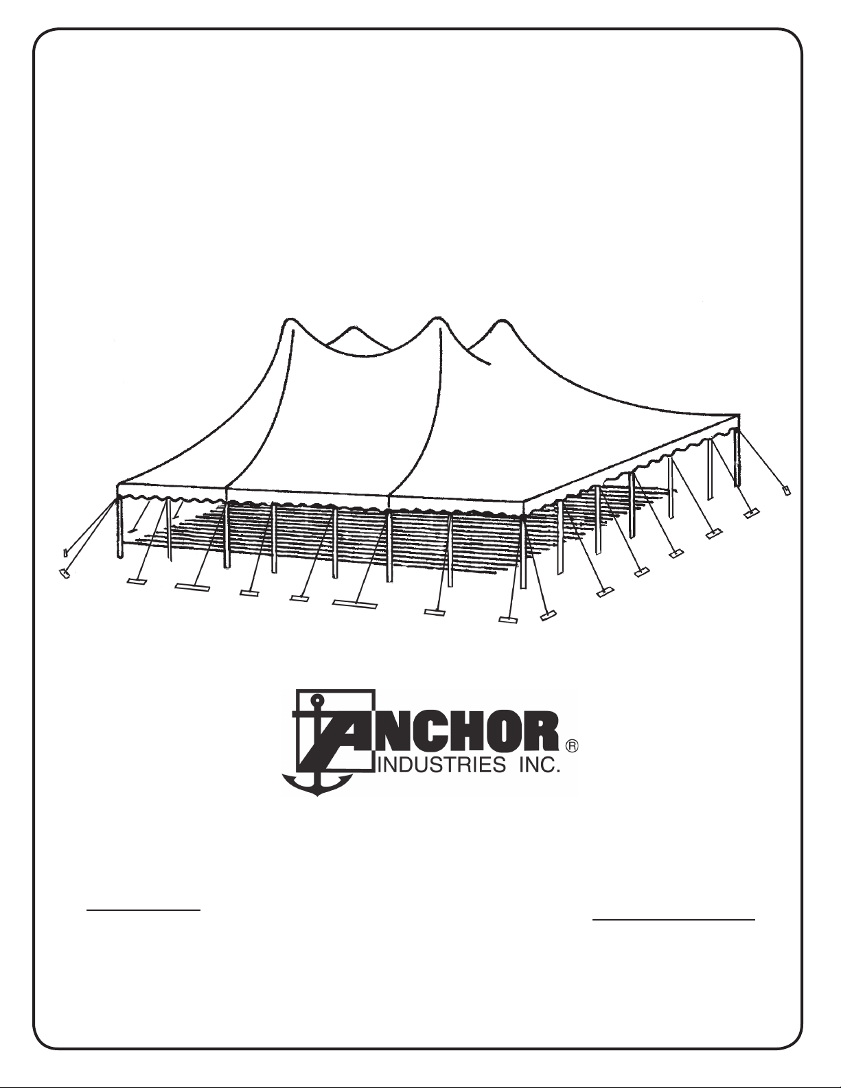
Assembly Instructions
60’ Wide System
NEW CENTURY® TENT
Please read all assembly / installation instructions before the installation or removal of this product.
PHONE: 812-867-2421
SALES OFFICES:
1100 BURCH DRIVE
PO BOX 3477
EVANSVILLE, IN 47733 USA
WEB
EC4435
Quality, Craftsmanship and Service since 1892
FAX: 812-867-0547
1-800-544-4445
EMAIL: tents@anchorinc.com
www.anchorinc.com
PRODUCTION FACILITY:
EVANSVILLE, IN
60CEN 1011
Page 2

Index
Introduction..........................................................................................................3
Safety Notes................................................................................................................ 3
Manpower/Tools Required ............................................................................................4
Parts Illustrations ..........................................................................................................4
Parts Illustrations Continued .........................................................................................5
Parts Quantities Table ..................................................................................................5
Web Guy Layout - Square End Tent ......................................................................6
Web Guy Layout - Round End Tent ........................................................................... 7
Web Guy - Staking Guidelines.................................................................................... 8
Layout at Site ................................................................................................................9
Lacing Instructions .....................................................................................................9
Pole Cap ....................................................................................................................10
Tie down after Lacing ...............................................................................................10
Raising Side Poles ....................................................................................................10
Raising Center Poles ................................................................................................11
Winch Tensioning........................................................................................................ 11
Final Adjustment and Take Down................................................................................. 12
Center Sections - Supplemental Instructions ...........................................................12
Center Sections - Supplemental Instructions Continued...........................................13
2
Page 3

Introduction
The installation of this Century Tent should be performed/supervised by knowledgeable tent installers with a clear understanding of safety issues as well as the methods of anchoring. The requirements as specified with blue print (supplied by
Anchor Industries Inc.) must be followed. The installer/owner must read the assembly instructions completely prior to any
installation. Particular attention must be given to anchoring! See Caution Statement on back page of this manual
Work from step to step.
Before erecting any tents or membrane structures, fi rst obtain permits and approvals as required from the local building and
fi re code offi cials on the jurisdiction of your installation.
PLEASE PAY SPECIAL ATTENTION TO SAFETY WARNINGS AND CAUTIONS FOR PREVENTION OF ACCIDENTS.
Regarding the contents of this document:
The illustrations and photos are made to show clearly the construction and dismantling procedures and also for identifi cation
of the components. Not all illustrations/photos correspond to the actual dimensions and size. Explanations and/or notes have
been added to these illustrations/photos.
If you have questions, please call your sales representative at the phone number listed on the front of this manual.
Safety Notes
Please read through this assembly manual completely before beginning your installation. Be sure the proper equipment •
and safety precautions are in place. We hope that you enjoy the design features of the tent each time the unit is installed.
Consult your local • utility locator service or the National Utility Locating Contractors Association
(NULCA) prior to installation.
•
Prior to actual tent assembly, be sure to look up, down, above & below for obstacles, pipes, wires, •
trouble, etc.
Be alert to avoid contact of Tent poles with any overhead power lines near the site.•
Keep site clear of debris to avoid tripping, especially while carrying tent poles or bundle of fabric.•
When moving tent sections by hand, use proper lifting techniques to protect the back.•
The installation method described here requires coordination of tasks between workers. A safe installation is dependent •
on that coordination. Work cooperatively as a team.
Replace used or damaged components with original new ones.•
To prevent injuries, wear suitable protective clothing such as hard hats, steel toed shoes, etc.•
Do not drag bundle of fabric on concrete, asphalt, or ground as this can cause damage to the fabric from abrasion through •
the bag.
This tent is manufactured for use as a temporary structure. Evacuation is recommended if threatening or windy weather •
occurs. See caution on back page of this manual.
3
Page 4
MANPOWER REQUIRED
Five experienced installers
should be able to assemble a
60’ x 70’ tent in approximately
four hours.
TOOLS REQUIRED
Sledge Hammers
Stake Driver
2 Measuring Tapes
LAYOUT & CHECK
Utilize parts list for a quick I.D. and a check list to
ensure that you have all the parts.
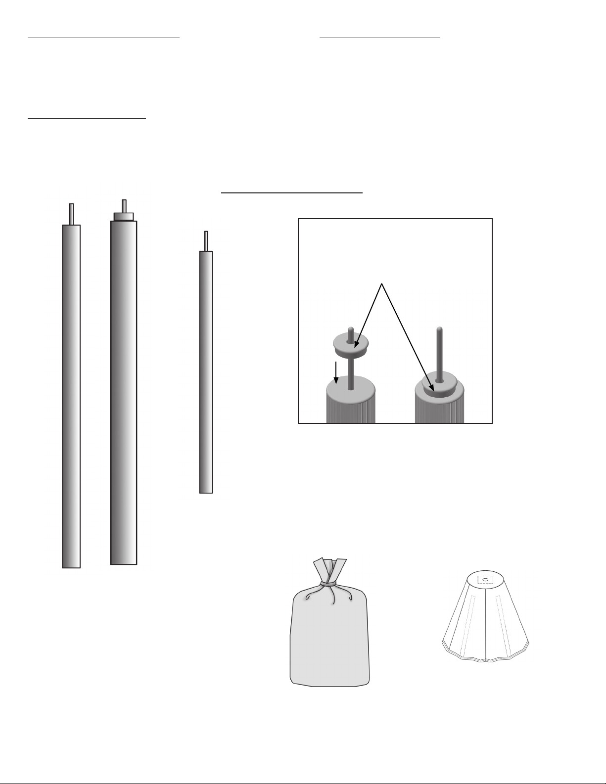
Parts Illustrations
Pole Adapter for
6” Center Pole only
Century 6” to 4” Pole Adapter. Slide on
top of 6” Pole Pin.
4” Pole
Center Pole
6” Pole
*
(used on 30’
ends only)
4” Schedule 40 Pipe Centerpole for up to &
including 8’-0” Side Pole Height.
6” Schedule 40 Pipe or 6” Fluted Centerpole
with Pole Adapter for OVER 8’-0” Side Pole
Height.
Side Pole
Pole Cap (optional)
Bag with Fabric
Section
4
Page 5
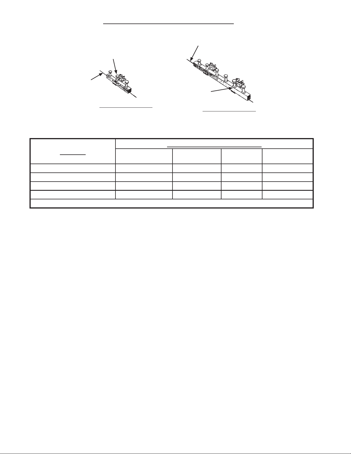
Parts Illustrations continued
Stake driven through
hole in bar and winch
plate
Stake line
Stake driven through
hole in bar and
winch plate
2’ STAKE BAR
Stake line
4’ STAKE BAR
QUANTITY PER SECTION
PARTS
BAG WITH FABRIC SECTION 2 2 1 1
CENTER POLE 2 2 2 2
SIDE POLE 20 24 4 6
POLE CAP (OPTIONAL) 2 2 2 2
SEE WEB GUY LAYOUTS & STAKING TABLES FOR STAKING REQUIREMENTS.
*
20’ END SQUARE
OR ROUND (PAIR)
30’ END (PAIR) 20’ MIDDLE 30’ MIDDLE
For 30’ Ends only
*
4” Schedule 40 Pipe Centerpole for up to & including 8’-0” Side Pole Height.
6” Schedule 40 Pipe Centerpole with Pole Adapter for OVER 8’-0” Side Pole Height. See
page 7 for adapter installation detail.
5
Page 6

WEB GUY LAYOUT*
1
Square End - Sample Layout
MARK LOCATION OF STAKES, SIDE POLES & CENTER POLES
LAYOUT SHOWS 20’ ENDS AND 30’ MID.
30’ ENDS AND 20’ MIDS USE IDENTICAL SPACING AND STAKING. SEE TABLE BELOW.
70’-0’ TENT LINE
** To find diagonal measurement:
diagonal = width² + length²
LOOP SIDE
SECTION
60’-0” TENT LINE
CENTER
POLE
(TYP)
AND (6) STAKES
END
USE DIAGONAL DIMENSION
TO SQUARE LAYOUT
(2) WEB GUYS WITH
(2) 2’ STAKE BARS
MIDDLE
SECTION
** 92’-2 3/8”
REQUIRED DISTANCE BETWEEN
SIDE POLES AND STAKE LINES:
7’ POLE STAKE OUT 5’-3”
HOLE SIDE
END
SECTION
8’ POLE STAKE OUT 6’-0”
10’ POLE STAKE OUT 7’-6”
WEB GUY WITH 2’ STAKE BAR AND
(3) 42” STAKES (TYP. AS SHOWN)
SIDE POLE
(TYP)
(2) WEB GUYS WITH 4’ STAKE
BAR AND (6) 42” DBL. HEAD STAKE
(TYP. AS SHOWN)
Illustration Item No. Description
Cen-
23000
tury Guy w/
Winch
37020A
3704242 (over 25)
42” Double
Hd. Stake
2’-0” Stake
33000
Bar w/ (3)
Holes
4’-0” Stake
33100
Bar w/ (6)
Holes
23100 Winch Tool
6
Staking Table
Qty. for
60’ x 40’
(2) 20’ Ends
26 30 26 6 8
78* 90* 78* 18* 24*
22 26 22 2 4
22 222
22 211
Qty. for
60’ x 60’
(2) 30’ Ends
Qty. for
60’ x 40’
(2) Round Ends
Qty. for
20’ Mid
Qty. for
30’ Mid
Page 7

Round End - Sample Layout
MARK LOCATION OF STAKES, SIDE POLES & CENTER POLES
60’-0” TENT LINE
40’-0’ TENT LINE
IMPORTANT NOTE: TO KEEP TOP FROM SPINNING, STAKE THE CORNER GUYS IN THE “X”
POSITION SHOWN WITH DASHED LINES UNTIL
THE CENTER POLES ARE UP, THEN UNDO THE “X”
STAKING AND POSITION THE GUYS AS SHOWN IN
SOLID LINES.
REQUIRED DISTANCE BETWEEN
SIDE POLES AND STAKE LINES:
7’ POLE STAKE OUT 5’-3”
8’ POLE STAKE OUT 6’-0”
10’ POLE STAKE OUT 7’-6”
(2) WEB GUYS WITH (2) 2’
STAKE BARS AND (6) STAKES
(TYP. AS SHOWN)
(2) WEB GUYS WITH 4’
STAKE BAR AND (6) 42” DBL.
HEAD STAKE (TYP. AS SHOWN)
WEB GUY WITH 2’
STAKE BAR AND (3) 42”
STAKES (TYP. AS SHOWN)
SEE STAKING GUIDELINES ON
NEXT PAGE.
* IMPORTANT NOTE: REFER TO CAUTION STATEMENT #2 FOR IMPORTANT WARNING ABOUT NUMBER OF
STAKES SUPPLIED. (SEE BACK PAGE OF THIS MANUAL)
THE INSTALLER MUST USE THE LOCAL SOIL CONDITIONS TO CALCULATE THE ACTUAL
NUMBER OF STAKES REQUIRED AND IS RESPONSIBLE FOR THE STAKING PATTERN AND
CONFIGURATION. ANCHOR PROVIDES ANCHORING PACKAGES FOR COMMON SOIL CLASSIFICATIONS;
CONTACT YOUR TENT SALES REPRESENTATIVE FOR MORE INFORMATION.
7
Page 8

WEB GUY - STAKING GUIDELINES
REQUIRED DISTANCE BETWEEN
SIDE POLES AND STAKE LINES:
7’ POLE STAKE OUT 5’ 3”
8’ POLE STAKE OUT 6’ 0”
10’ POLE STAKE OUT 7’ 6”
(1) WEB GUY
WITH 2’ STAKE BAR
AND (3) 42” DOUBLE
HEAD STAKES
(2) WEB GUYS
WITH 4’ STAKE BAR
AND (6) 42” DOUBLE
HEAD STAKES
(2) WEB GUYS WITH
(2) 2’ STAKE BARS
AND (6) STAKES
8
Page 9

LAYOUT AT SITE
2
Drive stakes at points located. Each 2’
stake bar requires 3 stakes. A 4’ stake bar
requires 6 stakes.
Spread drop cloths and unroll tent.
LACE
END
Any objects with sharp projections which
must remain on site under the tent should
be padded and taped.
NOTE: Both Loop side and hole side of
sections are required for proper lace.
LACING INSTRUCTIONS
3
With tent sections on ground, overlap center pole holes with grommet side on top.
Lace between center pole holes first. Push
first loop up through corresponding grommet. Continue, passing each loop through
a grommet and the preceding loop. See
illustration below.
Continue lacing process and cover lacing
with protective rain flaps by velcroing the
short flap first, then snapping the top flap to
the rope as you move toward other center
pole hole.
MIDDLE
END
STAKE
BARS
SEE WEB GUY LAYOUTS FOR
STAKING CONFIGURATIONS.
END
MIDDLE
CENTER POLE
HOLE
END
Tie off last long loop.
LACE LOOPS
Then lace from center pole to eave on
both sides of tent. Tie off last long loop.
Align plates and attach hook to plates on
inside of tent, as shown.
RING
FLAP
LACE ROPE
WALL ROPE
SNAP
LAST
LACING
LOOP
POLE HOLE
VIEW FROM
OUTSIDE
HOOK
PLATE
JUMP ROPE
VIEW
FROM
INSIDE
9
Page 10

POLE CAP (Optional)
4
Overlap the pole hole plates in the mid and end
fabric lace line. Push fabric and plates up into
cap and secure from underneath by threading
the female, flanged pipe coupling onto the male
pipe fitting molded to the inside top of the pole
cap.
MOLDED CAP W/
MALE THREADED
PIPE FITTING
POLE CAP
LACE LINE
END
FABRIC
MID
FABRIC
TIE DOWN AFTER LACING
5
After lacing and snapping sections, attach guys
and insert loosely into tension
winches.
Guy Web
Winch
Drum
WEB
RELEASE
(Push Downward)
Insert guy web into slot in winch drum and
rotate 1 1/2 to 2 times to secure web.
POLE PLATES
(OVERLAPPED)
WEBS ATTACHED
LOOSELY
FEMALE PIPE
COUPLING (FLANGED)
LACE
RAISE SIDE POLES
6
Start at downwind side. Insert each side
pole pin into side pole hole and raise
slightly less than perpendicular.
Bottom of each pole should be pointed
inward toward center of tent.
Wall ropes should run outside of corner
poles and side poles.
Tie jump rope around each side pole as it
is inserted in pole hole.
Continue around tent.
SEE WEB GUY LAYOUTS FOR
STAKING CONFIGURATIONS.
SIDE POLES INSTALLED
ON DOWNWIND SIDE
10
Page 11
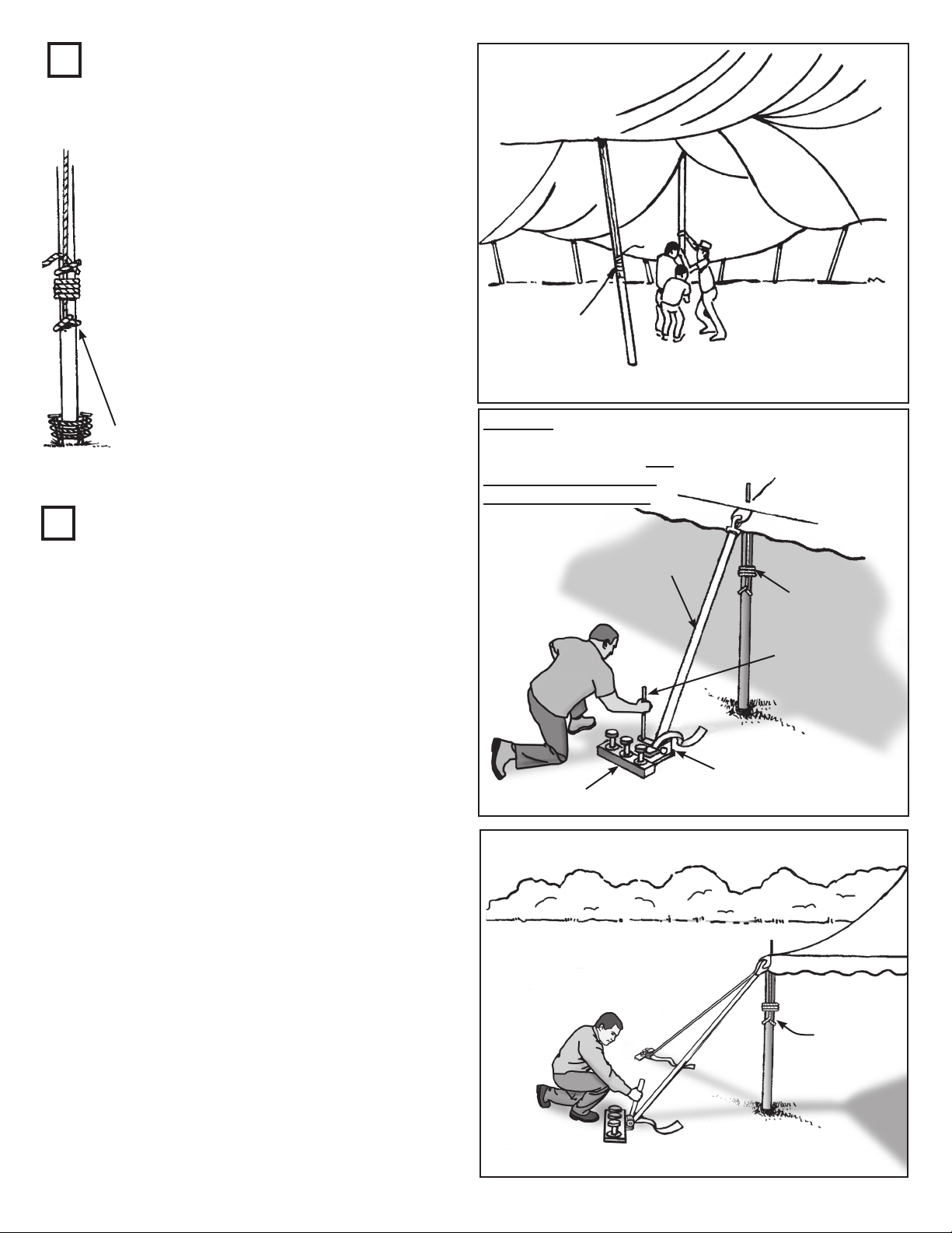
7
RAISE CENTER POLES
Raise center poles nearest to wind direction to approximate position.
One installer to guide center pole pin
through hole to prevent snagging or
tearing of fabric as pole is being raised
to position.
Keep pole at a slant until the other pole on
the same lace is raised. Tie jump ropes
as each center pole is placed in approximate position. Adjust bases of poles to
exact location and align poles vertically.
CAUTION: At this point it is
required that bases of all center poles be
properly anchored to prevent movement.
JUMP ROPE
JUMP ROPE
8
WINCH FOR TENSION
If the footprint of the tent has been laid
out properly and the tent placed squarely
within that footprint, the following tensioning sequence is recommended for the best
overall appearance:
1. Tension webs at the lace lines first.
2. Tension webs at the corners.
3. Tension webs at the ends.
4. Tension webs at the middles last.
NOTE: If the tent is not square, or if
center poles lean when laces are tensioned,
reverse steps “1” and “2” above.
At each side pole, release winch tension
and place bottom of side pole at the marked
footprint eave line location.
CAUTION:
KEEP TO SIDE OF WINCH
WHEN TENSIONING. DO
NOT EXTEND LENGTH
OF WINCH BAR TOOL.
WEB
JUMP
ROPE
WINCH BAR
TOOL
WINCH
STAKE BAR
Insert guy web into winch. Pull excess
through winch. Tension, using winch bar.
DO NOT USE EXTENDERS ON WINCH
BAR TOOL.
CAUTION -- DO NOT OVER TENSION
TENT BEYOND EAVE LINE. DO NOT
PULL SIDE POLES OR CENTER POLES
BEYOND VERTICAL POSITION.
JUMP
ROPE
11
Page 12

FINAL SIDE POLE
9
ADJUSTMENT
With side poles standing vertical and bases
at the marked side pole footprint locations,
ratchet webs to tension the top evenly.
Due to changes in climactic conditions,
periodic inspection and adjustment should
be made.
Protective covers are recommended for all
stakes and stake bars.
IMPORTANT
Check guys periodically for tightness and
maintenance of good condition.
Stakes provided are for average soil conditions.
Sandy soil or asphalt may require additional
staking. Proper installation suitable to site
conditions is the responsibility of the installer.
Store tent in a cool, dry area. Never store while
wet or damp.
10
TAKE DOWN
USE EXTREME CAUTION REMOVING
ALL POLES
1. Spread ground cover.
2. Loosen tension on all web winches.
3. Slant side poles inward.
4. Remove center and side poles.
5. Reverse installation steps.
SUPPLEMENTAL INSTRUCTIONS FOR TENTS WITH CENTER SECTIONS
USE WITH STEPS 1 THROUGH 8
MEASURE LAYOUT
1a
Mark location of stake line, tent line and
center poles.
(See pages 6 thru 8)
END
7’-0”
40 x 60
Center
END
20’-0”20’-0”
40’-0”
40’
END
LOOP
SIDE
40’ x 60’
CENTER
*
60’ END
LOOP SIDE
USE DIAGONAL M
TO SQUARE LAYOUT
ASUREMENT
E
*
40’
END
HOLE
SIDE
34º
4’ STAKE
BAR
7a
12
**
60’ END
HOLE SIDE
60’-0”
20’-0”
2’ STAKE
BAR
25º
7’-0”
20’-0”
RAISE CENTER POLES
Raise center poles on end nearest to wind direction to approximate position (see page 12 for further
instructions). Continue raising the center poles in this manner until the center section is reached. At the
center section, raise the next two poles on the center section at the same time as the center poles on
the last mid section.
sides of center section until all center poles are raised and secure.
*See asterisks on drawing above. After these poles are raised, continue out to all
Page 13

20’-0”20’-0”
60’ END
LOOP SIDE
(4) 2’ STAKE
BARS
3a
LACING
INSTRUCTIONS
6’-0”
10º
45º
5’-3”
END
10º
60 x 60
Center
END
5’-3”
6’-0”
60’-0”
CENTER
PLATE
60’
END
LOOP
SIDE
20’-0”
END
60’ x 60’
CENTER
USE DIAGONAL MEASUREME
*
TO SQUARE LAYOUT
**
60’ END
HOLE SIDE
60’-0”
NT
*
CENTER
*
60’
40’
END
END
HOLE
LOOP
SIDE
SIDE
20’-0”
END
8a
In addition to step #3
(see page 10), align plates
and attach bolt, washers
and eye nut.
Hook is not used at this
location. Use web guys
(as shown in Step 1a),
center plate and
eye nut to tie off at this
location.
WINCH FOR TENSION
Use winches at center section lace where
proper tension is needed for correct tie
down and wrinkle free structure.
Auger cable straight down into ground.
USE CAUTION WHEN OPERATING
WINCH.
END
LAST
LACING
LOOP
TIED
CENTER
END
CABLE FASTENED
TO EYENUT
UNDER TENT AND
AUGERED INTO
GROUND.
Stakes with bars shown only for illustrative purposes.
See Step 1a for correct staking layout.
13
Page 14

EVANSVILLE, INDIANA
PHONE NUMBER
812· 867· 2421
FAX NUMBER
812· 867· 0547
Anchor products are of superior design and operate best within the parameters of these instructions. It is imperative
that the instructions be carefully read and COMPLETELY FOLLOWED. Please read installation instructions before the
installation or removal of this product. Installation instructions are available online at www.anchorinc.com or by calling
1-800-544-4445.
CAUTION:
1. For each installation, the installer is solely responsible for evaluating the site and the proper securing method
determined. Some soils require different staking or securing than that provided with the tent. Due to this variety of
soil conditions, these are the manufacturer’s suggested sequence of installation procedures. Anchor’s responsibility
is limited to the manufacture of the tent parts and materials. We are not responsible for methods that installers may
choose to erect and secure the tent to the ground.
2. The number of stakes suggested in the installation instructions do not necessarily meet all or any relevant codes
on the site of the tent installation. The number of stakes suggested will, in many cases, keep the tent erected,
however, due to various soil conditions; these stakes will be insuf¿ cient to keep the tent secure in high winds.
It is the tent installer’s responsibility, not the manufacturer, to determine the appropriate number of stakes to meet
the necessary wind loads on the site. Regardless of the number of stakes we suggest, we make no representation
or warranty as to whether this speci¿ c number of stakes will meet the local tent code. Anchor does not, nor can
it make any suggestions, representation, or warranties about the adequate staking required at each speci¿ c
installation site. Staking information provided in the installation instructions is not a suggestion about what is
necessary to meet a site-speci¿ c load.
For additional important information, consult: “The IFAI Procedural Handbook For the Safe Installation and
Maintenance of Tentage” and the IFAI Pocket Guide “Pullout Capacity of Tent Stakes”, both available from
the IFAI Tent Rental Division or on our website.
3. Inasmuch as the weather is unpredictable, good judgment and common sense must be incorporated within
installation guidelines. It is the responsibility of the tent installer/maintainer to determine the severity of the weather,
proper time and method of installation and/or erection and disassembly. Note: We recommend that snow and
ice be removed from the tent surface as soon as possible because accumulation will damage the tent
or fabric structure. Please consult with our Engineering Department about the maximum loads for each
product.
This product has been manufactured for use as a temporary structure. For the safety of all occupants, evacuation
is recommended if threatening weather occurs, or if there is any doubt concerning the safe use of this product.
4. Proper safety equipment should be used at all times to insure a safe installation and take down. We suggest a
careful evaluation be made to determine safety equipment needed, such as hard hats, steel-toe shoes, safety
glasses and other as required. It is our desire that all installations are safe. Please be aware of hidden dangers
both underground, i.e., gas lines, water lines, electrical lines, etc. and above the tent such as power lines and
telephone lines.
5. Anchor stands behind its products in accordance with its standard Terms and Conditions of sale. A copy of our
Terms and Conditions of Sale can be obtained by contacting Anchor at the telephone number and/or address on
this document.
14
28.2 03-04-09
 Loading...