

Page 1
Assembly Instructions
100’ Wide, One-Piece System
NEW CENTURY® TENT
Please read all assembly / installation instructions before the installation or removal of this product.
SALES OFFICES:
1100 BURCH DRIVE
PO BOX 3477
EVANSVILLE, IN 47733 USA
WEB
EC4615
PHONE: 812-867-2421
FAX: 812-867-0547
1-800-544-4445
EMAIL: tents@anchorinc.com
www.anchorinc.com
PRODUCTION FACILITY:
EVANSVILLE, IN
Cen1pc100 1012
Page 2
IMPORTANT:
The installation of this Century Tent should be performed/supervised by knowledgeable tent installers with a clear
understanding of safety issues as well as the methods of anchoring. The requirements as specified with blue print
(supplied by Anchor Industries Inc.) must be followed. The installer/owner must read the assembly instructions completely prior to any installation. Particular attention must be given to anchoring! See Caution Statement on back page
of this manual.
MANPOWER REQUIRED
Six experienced installers should be able to
assemble a 100’ x 100’ tent in approximately
six hours.
TOOLS REQUIRED
Sledge Hammers
Stake Driver
2 Measuring Tapes
Front End Loader
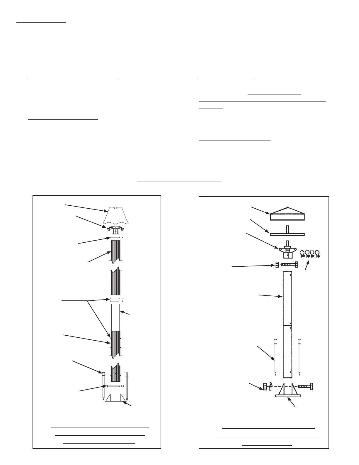
Parts Illustrations
Pole Cap
Top Weldment
1/2” x 8” Hex Head
Cap Screw with
washer and nut.
Top Pole Extrusion
INSPECT SITE
Caution:
Consult your local utility locator service or the
National Utility Locating Contractors Association
(NULCA) prior to installation. Prior to actual tent
assembly, be sure to look up, down, above &
below for obstacles, pipes, wires, trouble, etc.
LAYOUT & CHECK
Utilize parts list for a quick I.D. and a check list to
ensure that you have all the parts.
Pole Cap Fabric
Pole Cap Frame
Top Weldment
1/2” x 7 1/2” Hex
Head Cap Screw
with nut.
1/2” x 8” Hex Head Cap
Screws with washers
and nuts for attachment
of splice.
Bottom Pole
Extrusion
(4) 1” x 30” Double
Head Stakes
1” x 10” Hex Head
Cap Screw with
washer and nut.
Standard 7” Fluted Center
Pole Assembly for “Ring
Style” Construction
Splice
Tube
Base
Plate
(4) 3/4”
Shackles
2 Pc. Center Pole
(4) 1” x 30” Double
Head Stakes
1” x 10” Hex Head
Cap Screw with lock
washer and nut.
Base
Plate
Optional 8” Center Pole
Assembly for “Ring Style”
Construction
2
Page 3
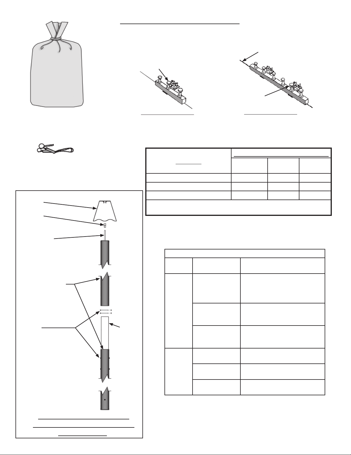
Parts Illustrations (cont’d)
Stake driven through
hole in bar and winch
plate
Stake driven through
Stake line
hole in bar and
winch plate
Stake line
Bag with Fabric
Maxi-Grip Flap
Tool - (1) per
Tent Section
Pole Cap
Coupling
Top Pole Pin
Section
2’ STAKE BAR
4’ STAKE BAR
QUANTITY PER SECTION
PARTS
BAG WITH FABRIC SECTION 2 1 1
CENTER POLE ASSEMBLY 2 2 2
SIDE POLE 32 6 10
SEE WEB GUY LAYOUTS & STAKING TABLES FOR STAKING
REQUIREMENTS.
APPROVED SIDE AND CENTER POLES
LENGTH SIZE
END (PAIR)
30’
MIDDLE
40’
MIDDLE
2 Pc. Center Pole
1/2” x 8” Hex Head Cap
Screws with washers
and nuts for attachment
of splice.
No Stakes
No Base Plate
Standard 7” Fluted Pole
Assembly for “Plate Style”
Construction
Splice
Tube
Side
Center
8’
10’
12’
37’
39’
41’
Alum. 2” Sch. 40 Pipe
Alum. 2 1/2” Sch. 40 Pipe
Alum. 3” Fluted
Alum. 3” Kedar Trac Fluted
Alum. 2 1/2” Sch. 40 Pipe
Alum. 3 1/2” Fluted
Alum. 3 1/2” Kedar Trac Fluted
Alum. 2 1/2” Sch. 40 Pipe
Alum. 3 1/2” Fluted
Alum. 3 1/2” Kedar Trac Fluted
Alum. 8” Ctr. Pole Assy.
Alum. 7” Fluted Assy.
Alum. 8” Ctr. Pole Assy.
Alum. 7” Fluted Assy.
Alum. 8” Ctr. Pole Assy.
Alum. 7” Fluted Assy.
3
Page 4
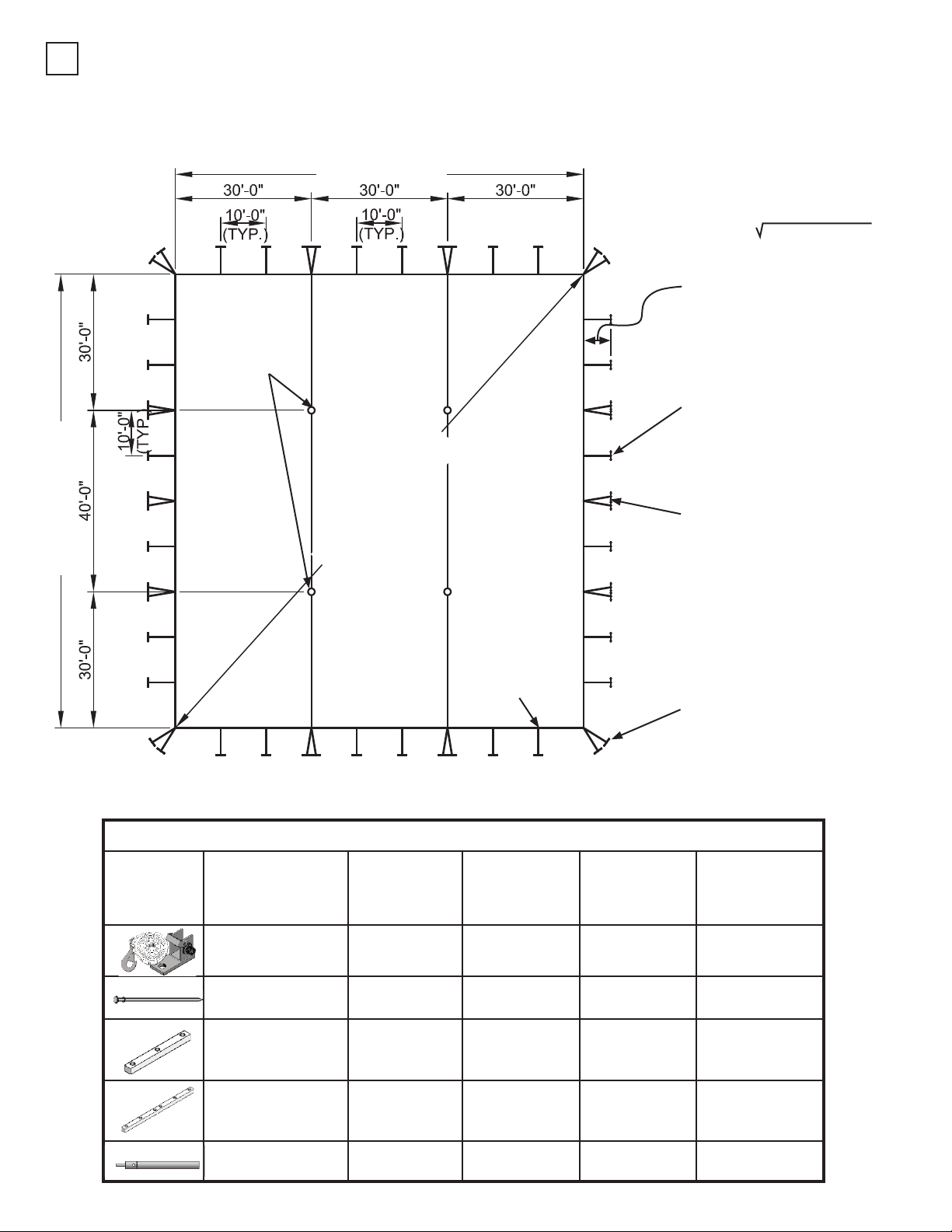
WEB GUY LAYOUT*
1
100’ one-pc. (2) Ends with 30’ Mid
MARK LOCATION OF STAKES, SIDE POLES & CENTER POLES
90’-0’ TENT LINE
CENTER
POLES
30’ MIDDLE
SECTION
** To find diagonal measurement:
diagonal = width² + length²
REQUIRED DISTANCE BETWEEN
SIDE POLES AND STAKE LINES:
7’ POLE STAKE OUT 5’-3”
8’ POLE STAKE OUT 6’-0”
10’ POLE STAKE OUT 7’-6”
WEB GUY WITH 2’ STAKE
BAR AND (3) 42” STAKES (TYP.
AS SHOWN)
100’-0” TENT LINE
Illustration Item No. Description
LOOP
SIDE
END
SECTION
HOLE
SIDE
END
** 134’-6 3/8”
TO SQUARE LAYOUT
USE DIAGONAL DIMENSION
SECTION
SIDE POLE
(TYP)
Staking Table
100’ x 60’
(2) 30’ Ends
Qty. for
Qty. for
30’ Mid
(2) WEB GUYS WITH 4’
STAKE BAR AND (6) 42” DBL.
HEAD STAKE (TYP. AS SHOWN)
(2) WEB GUYS
WITH (2) 2’ STAKE
BARS AND (6) STAKES
Qty. for
40’ Mid
23000
37020A
3704242 (over 25)
33000
33100
23100 Winch Tool
Century Guy
w/ Winch
42” Double
Hd. Stake
2’-0” Stake
Bar w/ (3)
Holes
4’-0” Stake
Bar w/ (6)
Holes
44 8 32
132* 24* 96*
28 4 8
8212
30 2
4
Page 5
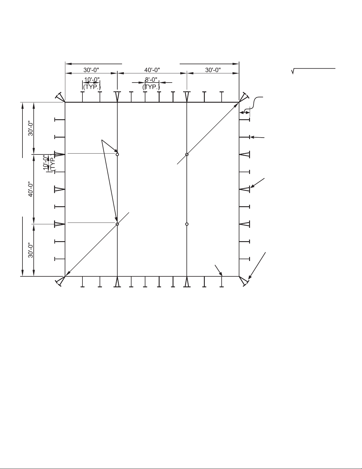
WEB GUY LAYOUT*
100’ one-pc. (2) Ends with 40’ Mid
MARK LOCATION OF STAKES, SIDE POLES & CENTER POLES
100’-0” TENT LINE
CENTER
POLES
LOOP
SIDE
END
SECTION
100’-0’ TENT LINE
40’ MIDDLE
SECTION
** 141’-5”
TO SQUARE LAYOUT
USE DIAGONAL DIMENSION
HOLE
SIDE
END
SECTION
** To find diagonal measurement:
diagonal = width² + length²
REQUIRED DISTANCE BETWEEN
SIDE POLES AND STAKE LINES:
7’ POLE STAKE OUT 5’-3”
8’ POLE STAKE OUT 6’-0”
10’ POLE STAKE OUT 7’-6”
WEB GUY WITH 2’ STAKE
BAR AND (3) 42” STAKES (TYP.
AS SHOWN)
(2) WEB GUYS WITH 4’
STAKE BAR AND (6) 42” DBL.
HEAD STAKE (TYP. AS SHOWN)
(2) WEB GUYS
SIDE POLE
(TYP)
WITH (2) 2’ STAKE
BARS AND (6) STAKES
SEE STAKING GUIDELINES ON
NEXT PAGE.
* IMPORTANT NOTE: REFER TO CAUTION STATEMENT #2 FOR IMPORTANT WARNING ABOUT NUMBER OF
STAKES SUPPLIED. (SEE BACK PAGE OF THIS MANUAL)
THE INSTALLER MUST USE THE LOCAL SOIL CONDITIONS TO CALCULATE THE ACTUAL
NUMBER OF STAKES REQUIRED AND IS RESPONSIBLE FOR THE STAKING PATTERN AND
CONFIGURATION. ANCHOR PROVIDES ANCHORING PACKAGES FOR COMMON SOIL CLASSIFICATIONS;
CONTACT YOUR TENT SALES REPRESENTATIVE FOR MORE INFORMATION.
5
Page 6

WEB GUY - STAKING GUIDELINES
REQUIRED DISTANCE
BETWEEN SIDE POLES
AND STAKE LINES:
8’ POLE STAKE OUT 6’ 0”
10’ POLE STAKE OUT 7’ 6”
12’ POLE STAKE OUT 9’ 0”
(1) WEB GUY
WITH 2’ STAKE BAR
AND (3) 42” DOUBLE
HEAD STAKES
TENT
CORNER
(2) WEB GUYS
WITH 4’ STAKE BAR
AND (6) 42” DOUBLE
HEAD STAKES
CORNER WEB
GUYS
(2) WEB GUYS WITH (2) 2’ STAKE BARS
AND (6) 42” DOUBLE HEAD STAKES
6
6
Page 7

TENT LAYOUT
2
Drive stakes at points located. Each 2’ stake bar requires (3) 42” double head stakes. Each 4’ stake bar requires (6) 42”
double head stakes.
Spread drop cloths and unroll tent.
Caution: Any objects with sharp projections which must remain on site under the tent should be padded and taped.
LACING
3
With tent sections on ground, overlap rings (or plates) at
center pole holes with grommet side on top. Starting at
end opposite long loop, lace between center pole holes
fi rst. Push fi rst loop up through corresponding grommet.
LACE
Continue lacing process. Attach ridge snap to ring as
you come to them. Tie off last long loop.
Cover lacing by joining protective fl aps using Maxi Grip
tool.
Secure fl ap with buckles at top and bottom.
Then lace from center pole to eave on both sides of tent.
Tie off last long loop. Align plates and attach hook on
inside of tent as shown.
Attach two guy webs through both plates.
Lace all sections of tent.
7
Page 8

4a
CENTER POLE TOP WELDMENT FOR “RING STYLE”
CONSTRUCTION
Set top weldment in center pole hole and connect to overlapping rings as shown.
Overlapping
Rings
Place pole cap over top weldment, and push fabric and weldment up into cap and secure from underneath by threading
the female coupling onto the male pipe fi tting molded to the
inside top of the pole cap.
Molded Cap with male
threaded pipe fi tting
Top Weldment with
Female coupling on
top.
4b
CENTER POLE TOP
WELDMENT FOR “PLATE
Female
Coupling
Molded Cap with male
threaded pipe fi tting
Top Weldment
Plate Style
Construction.
STYLE” CONSTRUCTION
Pole Cap - Overlap the pole hole plates in the mid and end
fabric lace line. Push fabric and plates up into cap and secure from underneath by threading the female, fl anged pipe
coupling onto the male pipe fi tting molded to the inside top
of the pole cap.
4c
OPTIONAL 8” CENTER
POLE FOR “RING STYLE”
CONSTRUCTION
Set top weldment in center pole hole and connect to overlapping rings with shackles provided.
Place assembled pole cap over pipe of top weldment. Attach
hinge pin to pipe extending through top of pole cap. Rotate
pole cap to align holes in pipes.
Note:
Pole cap assembly is illustrated on a separate sheet packed
with fabric top.
attach
with hitch
pin
Optional 8” Center.
Pole for Ring Style
Construction.
8
Page 9

Web to Winch
5
Insert guy web loosely into slot in winch drum, approximately 4’-0” for 8’-0” side pole and 1’-6” for 10’-0” side pole.
Rotate drum 1 1/2 to 2 times to secure web.
Repeat at all guy web locations.
Raise Side Poles
6
Start at side opposite wind. Insert each side pole pin into
side pole hole and raise slightly less than perpendicular.
Bottom of each pole should be pointed inward toward
center of tent.
Wall ropes are to be outside of corner and side pole.
Tie jump rope around each side pole as it is inserted in
pole hole.
Continue around tent.
9
Page 10

7
Raise Center Poles
Important Information to prevent/minmize tent damage prior to center poles being
erected.
1. Traditionally, raising all side poles prior to pushing center poles is acceptable, however, during a high wind install,
only raise the side poles as needed on the side of the tent that the center poles are being pushed from. This helps to
eliminate wind damage.
2. If wind is high, pre-drive a stake at center pole locations and use a rope to tie the center pole weldments down to pre-
vent the wind from picking them up and damaging the fabric.
3. Care should be taken not to place anything under the fabric that can be rubbed against. We recommend a short saw-
horse type of device to set the pole to working height during installation of the top weldments. Nothing should be used
that is higher than head height to the crew working under the fabric. The top weldments should never be allowed to
support the center pole when lying on the ground. Something should always hold the top of the pole off the ground.
4. The center poles should always be pushed up in a direction parallel to the length of the tent. The center poles should
always be pushed from the 100’ side. This puts the longest lace line curve in position to minimize fabric damage and
stress on the maxi-grip flaps.
5. All center poles should be assembled and pre-positioned in order to speed the process of erection. The fabric is most
vulnerable to damage during the installation process. Anything (in a safe manner) possible to speed the process
should be done.
6. Center poles should be positioned as closely as possible to the orientation that they will be pushed in. Rotation of the
poles once attached to the top weldments should be avoided
7. Sudden stresses to the poles and fabric should be avoided. When disengaging the center pole base plates from the
forks of the erection equipment, care should be taken not to have a sudden drop of the poles as may happen when the
base plate is allowed to slide off the forks when the forks are raised off the ground.
8. Once center pole erection is begun it should not be stopped until the tent is tensioned.
9. Maxi-grip flap connections should be double checked prior to raising the first pole. This is especially important if there
has been wind and the fabric has flexed considerably.
10. Fabric bunching around the top of the center poles during installation should be avoided. This is especially important on
the maxi-grip lace line locations. The fabric flexing and popping into position when placed in this condition puts a lot of
stress on the maxi-grip and it is hard to notice any opening in the flap. Extra care should be taken here.
11. The actual erection sequence of poles is somewhat dependent of the type and quantity of equipment that is available.
With one piece of equipment it will be necessary to partially raise a pole and temporarily stake that pole to prevent
movement, then relocate the equipment to push an adjacent pole, then return to the first pole. Base plates should be
kept flat on the ground at all times.
12. Care should be taken to avoid as much stress on the fabric as possible. The stress can be minimized if poles are
pushed up in a manner that reduces dragging of poles as much as possible.
10
Page 11

Raise Center Poles cont’d
7
Assemble center poles with base plates (where applicable). Raise center poles with top pointing downwind. With bottom of
center pole in bucket of front end loader, slowly guide top of pole under tent with installers as shown.
For Ring Style construction, connect top weldment to pole with bolt, washer, and nut at center pole hole.
For Plate Style construction, insert top pole pin into female coupling at center pole hole and tie jump rope to pole to prevent
pole pin from dislodging while raising pole.
Continue guiding top of pole to prevent snagging of fabric. Raise top of pole as high as possible by hand while moving forward with loader.
Set base plate down approximately ten feet from center pole position previously marked. Drive two 30’ stakes through holes
in plate.
Repeat with other poles. Placing bottoms of poles at locations previously marked. When in position, drive four 30” stakes
through holes in base plate.
Reposition fi rst pole to vertical position and stake.
With 120’ tent, raise a short pole to a slant and stake. Connect long pole (of same set) to top weldment. Do not raise. Raise
other short pole (of same set) fully and stake.
Then raise long pole and stake. Repeat for other set(s) of center poles.
Alternate method raising Center Poles using Two loaders
Wind
Center Poles
Having two loaders available can make installation faster and easier.
Using the same method just mentioned, the two center poles can be raised simultaneously without the requirement of setting
the baseplates 10’ from fi nal vertical position.
11
Page 12

Alternate method using Pole Sled (for use with fork truck or
front end loader with pallet fork attachment).
Using the pole sled makes it possible to keep the
center pole steadily attached to a loader with pallet
forks.
The pole sled may be turned to be used with base
plate or curved plate for pole with no base plate.
The tent is still put up in the same manner as already
outlined.
Connect chain with
shackles to loader to
prevent detachment.
Center Pole
Slide base plate under
gusset plates so it is held
fi rmly in place.
Slide forks into rectangular tubes.
Pole Sled
Pole Sled must be purchased
separately.
Connect chain with
shackles to loader to
prevent detachment.
Center Pole
Pole Sled used with no base plate.
Slide forks into rectangular tubes.
12
Page 13

Tension Guy Webs
8
Tension webs at laces that are parallel with the width of
tent fi rst and then at corners.
Next, tension guy webs at middle(s).
Work around the tent in a balanced manner so that tent is
tensioned as evenly all around as possible.
Caution - DO NOT OVER-TENSION TENT
BEYOND EAVE LINE.
Tension remaining guy webs.
At one side pole at a time, release winch tension and place
bottom of poles at previously marked eave line location.
Insert guy web into winch. Pull excess through winch.
Tension as needed using winch bar.
Do not use extenders on winch bar tool.
Final Side Pole Adjustment
9
With side poles standing vertical and bases at the marked side pole locations for the footprint, ratchet webs to tension
the top evenly.
Protective covers are recommended for all stakes and stake bars.
10
Take Down - Use Extreme Caution
Removing All Poles
1. Spread ground cover.
2. Release tension on all web guys.
3. Slant side poles inward - slowly and carefully.
4. Remove center and side poles.
5. Reverse installation steps.
IMPORTANT:
Check Guy Webs periodically for tightness
and good condition.
Store tent in a cool, dry area. Never store
while wet or damp.
13
Page 14

EVANSVILLE, INDIANA
PHONE NUMBER
812· 867· 2421
FAX NUMBER
812· 867· 0547
Anchor products are of superior design and operate best within the parameters of these instructions. It is imperative
that the instructions be carefully read and COMPLETELY FOLLOWED. Please read installation instructions before the
installation or removal of this product. Installation instructions are available online at www.anchorinc.com or by calling
1-800-544-4445.
CAUTION:
1. For each installation, the installer is solely responsible for evaluating the site and the proper securing method
determined. Some soils require different staking or securing than that provided with the tent. Due to this variety of
soil conditions, these are the manufacturer’s suggested sequence of installation procedures. Anchor’s responsibility
is limited to the manufacture of the tent parts and materials. We are not responsible for methods that installers may
choose to erect and secure the tent to the ground.
2. The number of stakes suggested in the installation instructions do not necessarily meet all or any relevant codes
on the site of the tent installation. The number of stakes suggested will, in many cases, keep the tent erected,
however, due to various soil conditions; these stakes will be insuf¿ cient to keep the tent secure in high winds.
It is the tent installer’s responsibility, not the manufacturer, to determine the appropriate number of stakes to meet
the necessary wind loads on the site. Regardless of the number of stakes we suggest, we make no representation
or warranty as to whether this speci¿ c number of stakes will meet the local tent code. Anchor does not, nor can
it make any suggestions, representation, or warranties about the adequate staking required at each speci¿ c
installation site. Staking information provided in the installation instructions is not a suggestion about what is
necessary to meet a site-speci¿ c load.
For additional important information, consult: “The IFAI Procedural Handbook For the Safe Installation and
Maintenance of Tentage” and the IFAI Pocket Guide “Pullout Capacity of Tent Stakes”, both available from
the IFAI Tent Rental Division or on our website.
3. Inasmuch as the weather is unpredictable, good judgment and common sense must be incorporated within
installation guidelines. It is the responsibility of the tent installer/maintainer to determine the severity of the weather,
proper time and method of installation and/or erection and disassembly. Note: We recommend that snow and
ice be removed from the tent surface as soon as possible because accumulation will damage the tent
or fabric structure. Please consult with our Engineering Department about the maximum loads for each
product.
This product has been manufactured for use as a temporary structure. For the safety of all occupants, evacuation
is recommended if threatening weather occurs, or if there is any doubt concerning the safe use of this product.
4. Proper safety equipment should be used at all times to insure a safe installation and take down. We suggest a
careful evaluation be made to determine safety equipment needed, such as hard hats, steel-toe shoes, safety
glasses and other as required. It is our desire that all installations are safe. Please be aware of hidden dangers
both underground, i.e., gas lines, water lines, electrical lines, etc. and above the tent such as power lines and
telephone lines.
5. Anchor stands behind its products in accordance with its standard Terms and Conditions of sale. A copy of our
Terms and Conditions of Sale can be obtained by contacting Anchor at the telephone number and/or address on
this document.
28.2 03-04-09
 Loading...