

Page 1

Sd-150
USER MANUAL
Rev.2 July 2020
Page 2

Page 3

USER MANUAL DENTAL UNIT SD-150 - REV. 2 JULY
PAGE
CONTENTS
1. OVERVIEW 2
2. WARRANTY 2
3. IDENTIFICATION 4
4. PRECAUTIONS 4
5. CLAUSES 6
6. TECHNICAL FEATURES 7
6.1. Chair 7
6.2. Dental Unit 7
7. TRANSPORT AND DIMENSIONS 8
8. DESCRIPTION OF THE DENTAL UNIT 9
8.1. Connections box 10
8.2. Pneumatic pedal 11
8.3. Instrument tray 12
8.4. Main keypad 14
8.5. Hydric unit 15
8.6. Hose support 17
8.7. Auxiliary keypad 18
8.8. Headrest 19
8.9. Optional armrest 19
9. SAFE MOVEMENTS 20
10. CLEANING AND STERILISATION 20
11. TECHNICAL DATA 21
ANNEX 1.
ANNEX 2. VS300 SUCTION VALVES KIT (DÜRR DENTAL) 23
ANNEX 3. TYP1 SUCTION SYSTEM (METASYS) 24
ANNEX 4. ECO SUCTION SYSTEM (METASYS) 25
ANNEX 5. SELF WATER SYSTEM KIT 26
ANNEX 6. CAS 1 COMBI-SEPARATOR (DÜRR DENTAL) 27
ANNEX 7. CS 1 SEPARATOR (DÜRR DENTAL) 27
ANNEX 8. WEK WATER DECONTAMINATION SYSTEM: (METASYS) 28
ANNEX 9. H1 HYGIENE SYSTEM (METASYS) 29
ANNEX 10. MINILIGHT SYRINGE (LUZZANI) 30
ANNEX 11. OPTIONAL COMPONENTS 33
ANNEX 12. CLEANING AND DISINFECTION OF OTHER EQUIPMENT PARTS 34
ANNEX 13. SAFETY OBSERVATIONS 35
ANNEX 14. SYMBOL DEFINITIONS 37
CLEANING AND DISINFECTION OF THE CATTANI TANK, HOSES AND BASIN
22
1
Page 4

USER MANUALDENTAL UNIT SD-150 - REV.2 JULY 2020
1. OVERVIEW
Thank you for purchasing the SD-150 dental unit.
This instruction manual contains information about the dental device, its set-up and maintenance.
Notes
This symbol means ALERT, CAUTION.
The User Manual must be read and understood before starting up the unit.
This manual should be kept in a safe place for future reference, for as long as
you use the equipment.
Follow all safety standards.
The user is in charge of keeping the unit in perfect operating conditions, clean
and disinfected.
This dental equipment is intended to be used exclusively by a professional user who must be
properly trained and licensed to practice dental medicine.
This equipment can only be handled by an authorised technical service.
Keep the unit installed in an environment under controlled conditions, including temperature
range (+10˚C to +40˚C), humidity (30-75%) and atmospheric pressure (700 to 1060 hPa), free
of condensation and dust and not exposed to direct sunlight.
The electrical installation of the premises where the equipment is installed must comply with the
instructions set forth in standard EN 60601-1 referring to electrical protections against electric
shock for Class I equipment.
Antoni Carles, S.A. reserves the right to make improvements or changes to this dental
equipment without prior notice.
The equipment must be used according to the instructions of use.
As per Directive 93/42/EEC, the dental unit and orthordintic chair manufactured by Antoni
Carles, S.A. are Class IIa equipment. It is strictly forbidden to install any Class IIb or Class III
dental instruments, such as surgical lasers, electro scalpels, X-rays, electrical cauterizers. Only
Class I or Class IIa devices can be installed and these must comply with the requirements set
forth in the aforementioned directive and harmonised standards EN60601-1 and EN60601-1-2.
2. WARRANTY
The units manufactured by ANTONI CARLES, S.A. are guaranteed against material and
manufacturing defects for 2 years from the date of installation, which must be registered
correctly in an online form. During this period, ANTONI CARLES, S.A. assumes the repair of
those parts or components of the unit that, once veried, are recognised as defective.
Under no circumstances shall ANTONI CARLES, S.A. be held responsible for defects and
damage caused by:
Natural wear of parts and components such as seals, lters, etc.
Inappropriate use, maintenance or cleaning of the unit and its components.
Accidental impacts or any other accidental cause or effects caused by user negligence.
Causes unrelated to the design or manufacture of the product or resulting from natural
phenomena such as electrical power outages, oods, etc.
Defects, intended damage or modications caused by third parties unrelated to Ancar.
Non-compliance with the maintenance periods specied in the User Manual or resulting from
inadequate repair or maintenance that has not been carried out by an ofcial Ancar technical
service.
2
Page 5

USER MANUAL DENTAL UNIT SD-150 - REV. 2 JULY
The use of spare parts that are not original, recommended or manufactured by Ancar.
ANCAR shall not be held responsible under any circumstances for damage and losses derived
from defective parts or materials, whether direct or consequential.
In no case shall ANCAR be required to replace the entire unit or to reimburse its purchase price.
ANTONI CARLES, S.A.'s responsibility and accountability for any damages shall cease in the
following cases, whereby the warranty shall be automatically cancelled:
1. If the registry is not formalised by the distributor within 30 days from the date of installation.
If interventions on the device are not carried out by technicians certied by ANTONI CARLES, S.A.
2.
3. If incorrect maintenance or installation operations are carried out on the unit, or non-original
spare parts are used.
4. If the installations required for operation of the unit (electrical, water and pneumatic) are
carried out without observing the instructions in the Installation Manual or the provisions of the
current standards of the country of use are not observed.
5. If non-authorised modications are made on the unit, or other medical devices and/or
accessories not foreseen by ANTONI CARLES S.A. are connected to it.
6. If the maintenance schedule included in the User Manual is not followed.
Ancar does not cover any labour costs for repairs under the warranty.
The warranty for the integrated elements of other brands, will be that granted by each of the
respective manufacturers, and for which ANTONI CARLES S.A. shall not assume any liability
or obligation with regard to said warranty.
To obtain technical service, please contact an ofcial distributor of ANTONI CARLES,S.A.
(refer to the list of distributors in:
- SPA: www.ancar-online.com/distribuidores-dentales/
- ENG: www.ancar-online.com/en/distribuidores/
- FR: www.ancar-online.com/fr/distributeurs/
- DE: www.ancar-online.com/de/fachhaendler/).
ANTONI CARLES, S.A. reserves the right to modify the warranty conditions available for the
Customer at any time, insofar as permitted by current legislation.
3
Page 6

USER MANUALDENTAL UNIT SD-150 - REV.2 JULY 2020
3. IDENTIFICATION
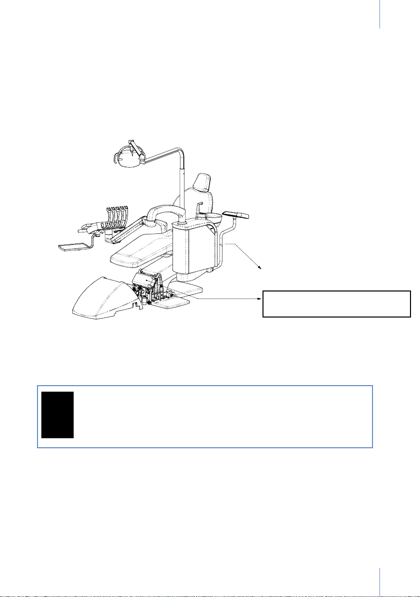
The identication label, which contains the technical information needed for connection, is
folded.
It can be seen from the rear of the seat and is also placed near the base, on the side of the chair.
This second label will be seen once the outer cover is removed (Fig. 1).
4. PRECAUTIONS
The unit must be installed in a location with plenty of light, away from areas transitted by people
and must have enough free space available to ensure that the patient and professional are
comfortable.
The dental chair must be anchored to the oor to guarantee stability.
Before moving the chair, the operator (doctor, user) must ensure that nobody else (patient,
companion, children) is in the chair's eld of action. Be especially careful as regards persons
present in the area of the backrest and the instrument tray.
After using the equipment, disconnect all the instruments and the unit. The unit must be
switched off at the end of the work day.
If the unit is not going to be used for a long period of time, the plug to the power supply must also
be disconnected and the main water and air valves should be closed.
Make sure that the main switch (Fig. 4, "J") is disconnected if the equipment is not under
direct supervision by staff. This will prevent the water intake ducts from withstanding constant
pressure. To prevent equipment malfunctions and damage to the property, the air and water
intake pressures must not exceed 6 bar and the hoses must not be exposed to temperatures
over 46ºC.
Do not overload the unit to maintain the useful life of the lifting unit components.
It is not advisable to use mobile phones near the unit when it is in operation.
This equipment is not designed to be used inside surgery rooms.
4
Page 7
USER MANUAL DENTAL UNIT SD-150 - REV. 2 JULY
PRESERVATION OF THE ENVIRONMENT
All the materials used for packaging respect the environment and are recyclable: wooden
pallet, cardboard, polyethylene bag and bubble lm. Collection of the materials used favours
recovery, recycling and reduction of waste material.
Antoni Carles, S.A. is committed to achieving the objectives set forth in European Community
Directives 2011/65/EC and 2012/19/EC.
Location of the label
SN: N (Electro-pneumatic unit)+number
Nxxxx
This symbol is only applicable for member states of the European Union.
To prevent potential negative consequences for the environment or human
health, this equipment must be disposed of (i) in EU member countries according to the WEEE (Directive on Waste Electric and Electronic Equipment)
and (ii) in all other countries, according to local regulations and recycling
legislation.
EMC
The dental equipment model Sd-150 complies with the essential requirements that apply to it
as set forth in the Medical Device Directive 93/42/EEC and meets the design and construction
requirements contained in standard EN60601-1-2 on the Safety of Medical Electrical Equipment
and Electromagnetic Compatibility; therefore it does not cause electromagnetic disturbances
and complies with immunity standards.
5
Page 8

USER MANUALDENTAL UNIT SD-150 - REV.2 JULY 2020
ENVIRONMENTAL CONDITIONS
When packaged for transport and storage, the equipment can withstand exposure up to 15
weeks to environmental conditions that do not exceed:
a) ambient temperatures between -20˚C and +50˚C.
b) relative humidity between 10% and 100%, including condensation.
c) atmospheric pressure between 500 hPa and 1060 hPa (from 500 mbar to 1060 mbar).
- Operating conditions:
d) ambient temperatures between +10˚C and +40˚C.
e) relative humidity between 30% and 75%, including condensation.
f) atmospheric pressure between 700 hPa and 1060 hPa (from 700 mbar to 1060 mbar).
5. CLAUSES
Antoni Carles, S.A. shall not be liable for damage due to re, natural disasters, actions
undertaken by third parties or other accidents (caused by the negligence or misuse of the
operator) or due to the use of the unit under unusual conditions.
Antoni Carles, S.A. shall not be liable for damage derived from inappropriate use of the device,
such as loss of business or loss of prots.
Antoni Carles, S.A. shall not be liable for the results of diagnoses made by a doctor when
using this device.
6
Page 9

USER MANUAL DENTAL UNIT SD-150 - REV. 2 JULY
6. TECHNICAL FEATURES
6.1. Chair
Ergonomic design for the patient.
Chair movements powered by lifting gears that are silent and fully reliable.
Movements controlled by a microprocessor:
- Automatic return to zero movement (adjustable height).
- Automatic return movement to the cuspidor.
- 3 free positioning memories (settings for seat height and backrest).
High-quality and hygienic anatomic upholstery.
Safe backrest and seat movements, with automatic unlocking manoeuvre.
Adjustable headrest height and positioning.
Trendelenburg position included.
6.2. Dental Unit
Easy care and maintenance paint.
Instrument tray for 5 instruments and control panel with 14 functions. Includes syringe.
Optional: adjustable electric micromotor. Reversible direction of rotation.
Connection available for instruments equipped with lighting (micromotor, turbine, ultrasound).
Hydric box with 70º rotation, cuspidor with automatic cup ller and basin cleaning. A variety of
suction and amalgam systems can be ordered separately.
Arm movements compensated with a pneumatic brake, with an auxiliary instrument tray.
Connections box and tubes located at the front of the chair.
Control panels on the instrument tray and hose support.
The equipment has been designed and constructed so that no tubes or cables are visible from
the outside, with the exception of the hoses on the instrument tray.
The equipment complies with the essential requirements that apply to it, as set forth in the
Medical Device Directive 93/42/EEC, meets the design and construction requirements contained
in standards EN60601-1 and EN60601-1-2 on the Safety of Medical Electrical Equipment and
Electromagnetic Compatibility and has undergone a Risk Management analysis in accordance
with standard ISO 14971.
7
Page 10
USER MANUALDENTAL UNIT SD-150 - REV.2 JULY 2020
0$;
7. TRANSPORT AND DIMENSIONS
The dental unit is delivered perfectly packaged and protected.
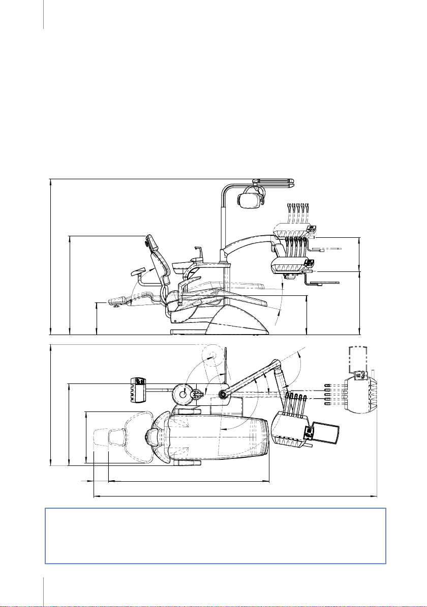
One box contains the dental chair attached to a pallet and the other two boxes contain the
hydric box and whip arm system, respectively. (Figure 2)
It is essential that none of these boxes undergo impacts during transport and they must not fall on
the ground under any circumstance. We urge the utmost caution to be exercised during transport
of the equipment, which must be carried out by technical staff authorised by Antoni Carles, S.A.
Before the equipment is assembled, for your convenience and to ensure ergonomic working
conditions, a technician will accompany you and any authorised staff at the work site to plan
the ideal location for the equipment.
Fig. 2
0,10$;
0,1
0$;
0,1
0$;
$;
0
0,1
0$;
If the unit has to be transported after being assembled, position the seat of the
chair at its minimum height with the backrest raised and make sure the hydric
box and instrument tray unit is placed and secured as far back as possible on
the chair at all times.
Remember to anchor the chair to the oor at its new location.
8
Page 11
USER MANUAL DENTAL UNIT SD-150 - REV. 2 JULY
8. DESCRIPTION OF THE DENTAL UNIT
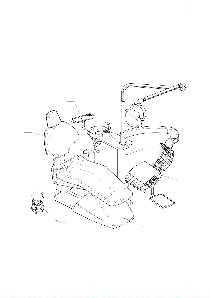
(A) Fig. 4 Connections box Page 10
(B) Fig. 5 Electro-pneumatic pedal Page 11
(F) Fig. 6-7 Instrument tray + main keypad Pages 12, 14
(E) Fig. 8-13 Hydric unit Pages 15, 16
(D) Fig. 14-17 Hose support + auxiliary keypad Pages 17, 19
(C) Fig. 18-19 Chair Page 19
D
C
E
Fig. 3
F
B
A
9
Page 12
USER MANUALDENTAL UNIT SD-150 - REV.2 JULY 2020
A
B
C
D
J
H
G
8.1. Connections box
The connections box contains all the connections required to connect the dental equipment to
the clinic's mains power supply and the air and water adjustment components. Valve movement
direction complies with standard UNE 20128.
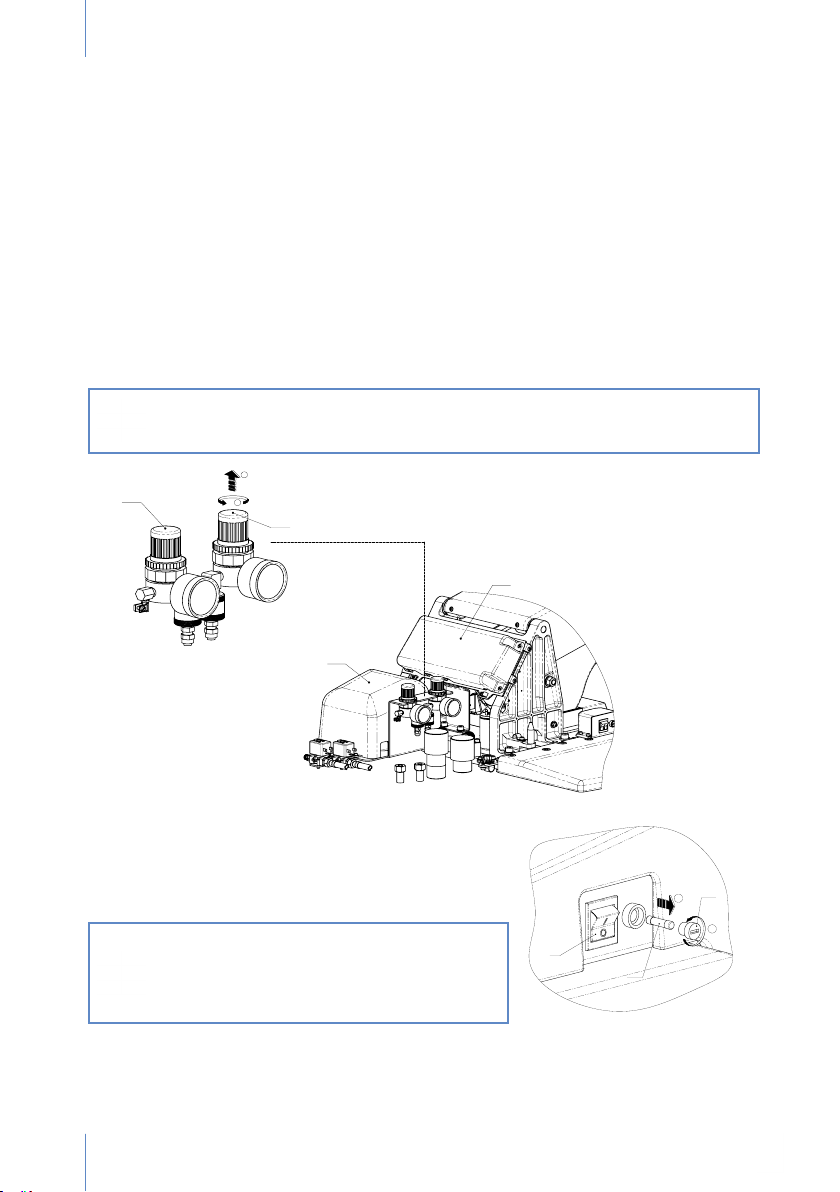
The following are shown in the detailed view of the front of the chair base:
A. Electronic movements card cover.
B. Electronic connections card cover and transformer.
C. Water intake pressure control. Equipped with a solid particles lter. Inspect once a month.
Clean with pressurised water. To change water adjustment, pull (“1”) and turn (“2”).
D. Air intake pressure control. Equipped with a solid particles lter. Inspect once a month.
Clean with pressurised water. To change air adjustment, pull (“1”) and turn (“2”).
The intake water must be free of impurities.
The compressor must be correctly installed to prevent humidity from accumulating in the
air circuit.
Note: When the main switch is connected, the connections card checks
functionality and emits a beeping sound. If this sound is not heard, switch the
unit off and contact an authorised technical service.
Fig. 4
The following elements are found on one side of the
connections box:
Main switch (J). Up, On; Down, Off. Lighted.
Main fuse (H), value T6.3A/L/250V, type 5x20mm.
The fuses (G) must be replaced by an authorised
technician.
This switch must be disconnected when the
equipment is not under direct supervision.
This prevents the water channelling ducts
from undergoing constant pressure through
the intake.
10
Page 13
USER MANUAL DENTAL UNIT SD-150 - REV. 2 JULY
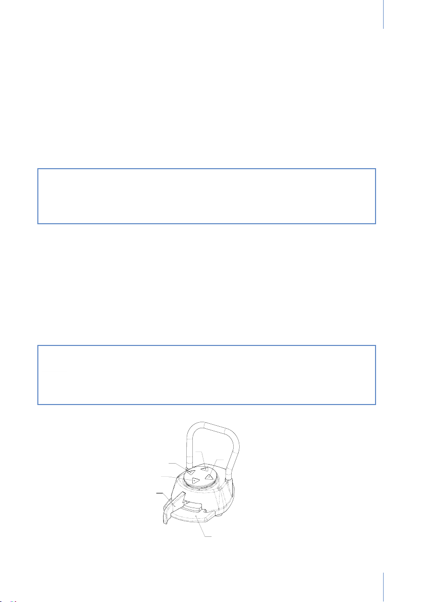
8.2. Electro-pneumatic pedal:
USE AND INSTALLATION
This pedal is used for proportional adjustment of the optional instruments in the instrument tray:
micromotor, turbine. Ultrasound On/Off (Fig. 5).
Regulates the rotation speed of the electrical micromotor, turbine power and pneumatic
micromotor by moving the handle (B); only with air or also with water to spray by pressing the
lever (A). Speed regulation with the electro-pneumatic pedal is particularly useful for the electric
micromotor since regulation is very sensitive and gradual.
“Chip blower” function by pressing the lever (A) when the handle (B) is at the rest position.
It does not regulate hose support instruments, but only instruments on the instrument tray.
Hygiene of optional instruments: turbines and micromotors, expelling the last
drop of water by automatic air blowing.
Safe movements for all the optional instruments of the instrument tray: when
the regulation lever is moved, the chair stops all its movements and is locked
in place.
PEDAL FUNCTIONS
A. Chip air lever. Short burst of air.
B. Handle to start up and proportionally adjust the instrument selected previously on the
instrument tray.
Moving the handle (B): only air, no water.
Moving the handle (B) and lever (A): water and air, spray function.
C. Backrest raising movement.
D. Chair lowering movement.
E. Backrest lowering movement.
F. Chair raising movement.
Safety:
To block any of the memories activated by the keys, press the regulating pedal.
Chair movements will be blocked while the regulating pedal is activated.
The pedal has the option of being set to zero automatically. This option is not
included initially.
F
E
C
D
B
A
Fig. 5
11
Page 14

USER MANUALDENTAL UNIT SD-150 - REV.2 JULY 2020
8.3. Instrument tray
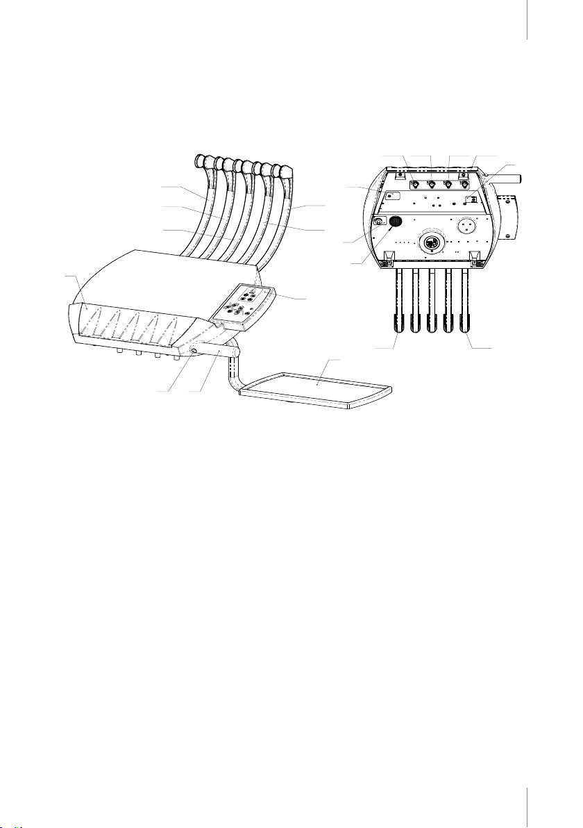
The instrument tray (Fig. 6) has an ergonomic design to facilitate the work of the user and an
auxiliary instrument tray (A), slightly angled toward the main keypad (B) to optimise viewing, as
well as a comfortable handle for movements (C). The button located at the front (D) is used to
unlock the pneumatic brake and change the height.
Use the handle on the tray to move it.
Do not pull on the hoses!
The layout of the instruments (P) consists of up to ve (1,2,3,4,5) positions that can be
congured in the plant as ordered.
Any subsequent change must be performed by an authorised technical service.
The turbine and electrical or pneumatic motor can be placed in any of these positions, from
position 1 to position 4.
Once the locations have been decided, the turbine and pneumatic micromotors can be
interchanged.
- Silicone instrument support (E) to protect the instruments against impacts. Easy to remove
and sterilise in an autoclave.
- Installation of the auxiliary instrument tray. Protective mat supplied.
- Its smooth, rounded lines and pore-free tray ensure accessible and fast cleaning and
disinfection.
- Arm levelling (only by an authorised technician).
- Arm brake adjustment (only by an authorised technician).
- Instruments with poles at the top to prevent instruments from falling.
- Instrument turbine ash light effect, without using the pedal.
- Instrument tray: vertical movement, 39 cm; horizontal movement, 75°, left, 50° right.
LOWER TRAY AREA:
The water regulators are located alongside each optional instrument (installation on request).
R (1, 2, 3, 4) Water regulators aligned alongside each optional instrument, installed on request
(micromotor, micromotor light, turbine, turbine light or ultrasound, respectively).
F Ultrasound power regulator.
G Micromotor rotation direction selector.
If the turbines or micromotors do not perform the spray function or water is not
available in the ultrasound, check that the regulators are open by turning them
counter-clockwise.
J Electric micromotor working mode selector: normal or gear mode. This is used to select
between work at low speeds of approximately 0 to 3,000 rpm.
K Removable tank for the return lter of the oil that lubricates the turbine and micromotor.
Inspect regularly.
12
Page 15
USER MANUAL DENTAL UNIT SD-150 - REV. 2 JULY
P5
P4
P3
P2
P1
A
B
C
E
D
R1R2R3R4
G
F
K
J
P1
P5
The tray is joined to the equipment by a pantograph arm with a pneumatic brake to ensure a
comfortable, effortless position at the front (handle side).
13
Page 16
USER MANUALDENTAL UNIT SD-150 - REV.2 JULY 2020
A
B
L
K
J
C
D
E
H
G
F
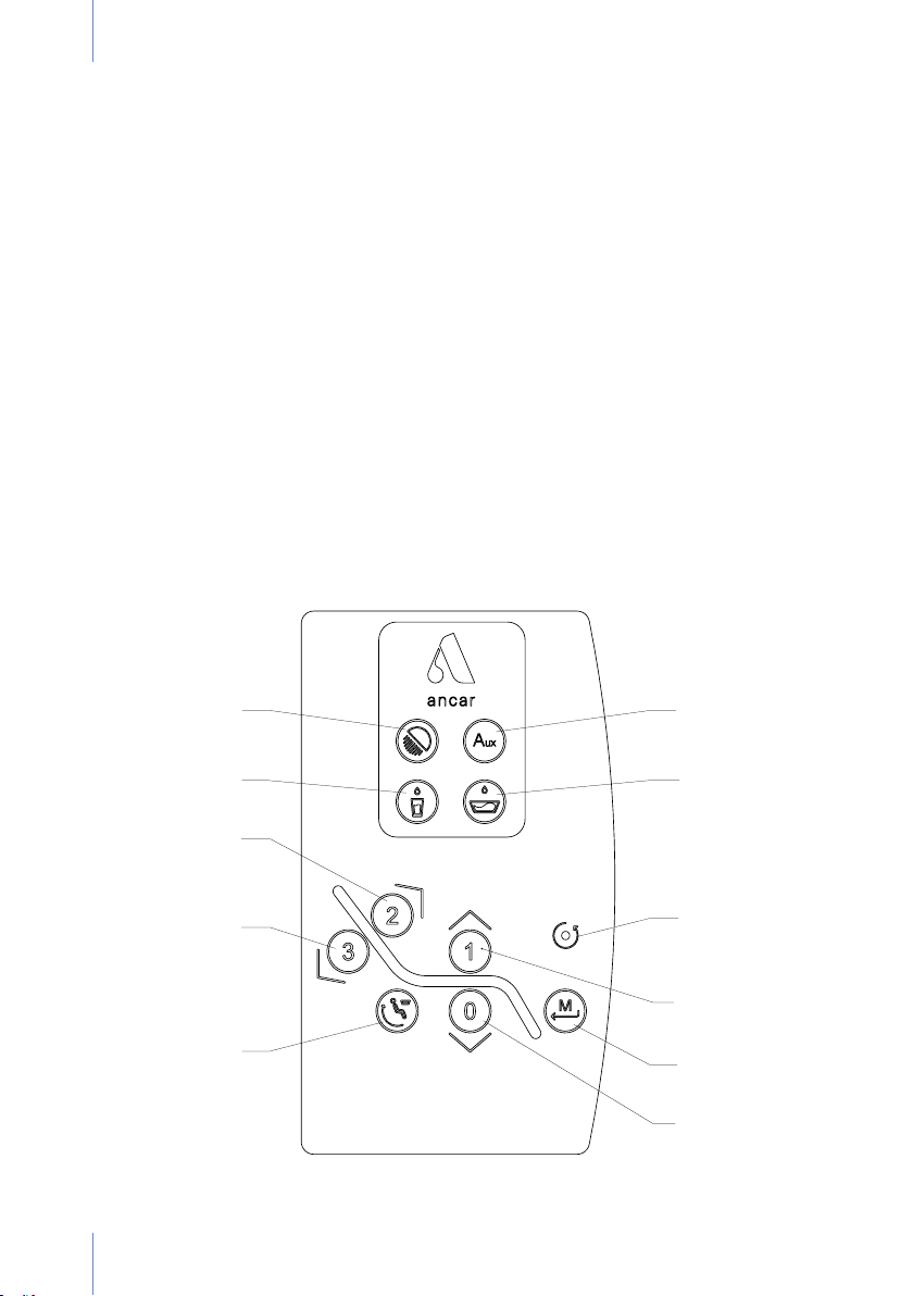
8.4. Main keypad
A. Activation of the dental operation lamp (ON / OFF).
B. Tank and cuspidor water. Timer, 2-12 seconds. If the basin and water have been set to work
at the same time, both will be activated. They can also be set independently (tank only).
C Press and hold: Raises the backrest manually.
Press once: Automatic movement to free position 2 in the memory.
D. Press and hold: Lowers the backrest manually.
Press once: Automatic movement to free position 3 in the memory.
E. Return to cuspidor. The rst press will move the backrest to the cuspidor.
When pressed a second time, the backrest returns to its initial position.
F. Activation of the auxiliary switch function (potential free contact).
This can be congured as a switch or push button.
G. Cuspidor water. Timer, max. 3 min. It is switched off by using the same function.
H. Yellow led that indicates reverse rotation of the electric micromotor.
J. Press and hold: Raises the chair manually.
Press once: Automatic movement to free position 1 in the memory.
K. Key to save free positions in the memory (1,2,3) for chair movements. Return to zero must
be performed previously. Position the chair as desired using the manual function keys.
Continue pressing the “Enter” (“K”) key, press any of the three positions (1, 2, or 3) and wait
for the OK “beep” to conrm. Release the "Enter" (K) key.
L. Press and hold: Lowers the chair manually.
Press once: Automatic Return to Zero.
Fig. 7
14
Page 17
USER MANUAL DENTAL UNIT SD-150 - REV. 2 JULY
A
B
C
D
70°
MAX. 90°
1
K
2
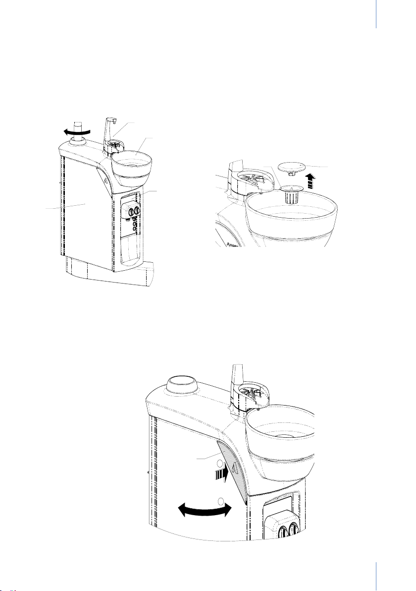
8.5. Hydric unit
The hydric unit rotates approximately 70° in relation to the support arm, increasing ergonomic
comfort for daily work. The upper part contains the tank support (A) and basin (B), made of
porcelain to provide a high degree of hygiene (Fig. 8).
Fig. 8
FE
Fig. 9
To prevent splashes and passage of solid particles, the basin is equipped with a lter (E) and a
lid (F) in the basin drain (Fig. 9).
The front panel (C) houses the hose lter and (D) is the side door of the hydric unit (Fig. 10).
Press the upper corner (K), softly in (“1”) to open the door (“2”). Remember not to open it more
than 90°.
Fig. 10
15
Page 18
USER MANUALDENTAL UNIT SD-150 - REV.2 JULY 2020
G
H
J
A
B
C
D
70°
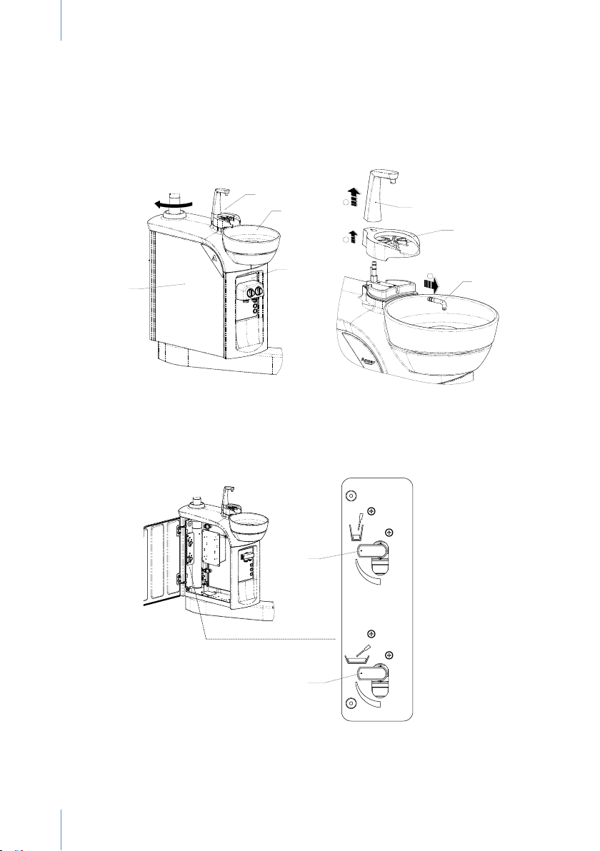
The porcelain part of the basin can be easily removed by following the steps in Figure 11 and
those in Fig.12 for the tap.
Remove the tap rst. (Fig. 12). To remove the tap, rst pull up (“1”) on the tank tap (G), then
remove (“2”) the tank support (H) to access the basin tap (J) and remove it (“3”).
To remove the basin (Fig. 12), rotate the basin (B) 180° (“1”) and pull it upwards (“2”).
Fig. 11
Fig. 12
On the inside there are two shut-off valves to adjust the tank water (L) and the basin water (M)
(Fig. 13).
L
16
M
Fig. 13
Page 19
USER MANUAL DENTAL UNIT SD-150 - REV. 2 JULY
A
B
C D
E
F
G
H
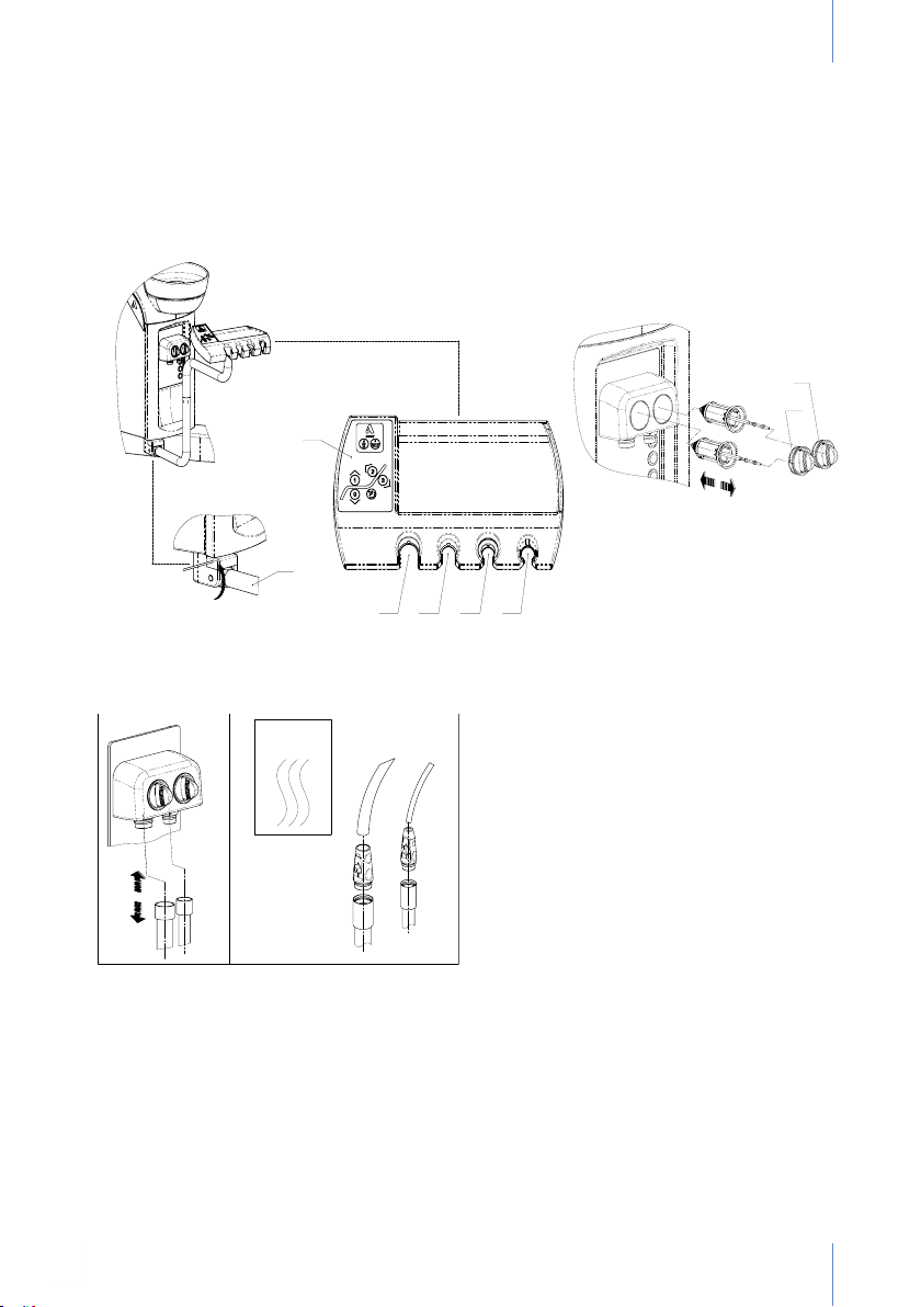
8.6. Hose Support (surgical suction, instruments, auxiliary keypad)
The hose support is mounted on an arm with a high capacity of movement to reach the desired
position. The hose support is equipped with an auxiliary keypad (A), medium and full suction (B
and C) and can be delivered with optional instruments, such as the 3F syringe (always placed
in position E), a polymerising lamp or intra-oral camera (pos. D).
Fig. 15
Fig. 14
The safety feature of the hose support is connected to the pedal and blocks any automatic or
manual movement to prevent the arm support from angling even slightly (F). This safety feature
is especially useful to prevent unexpected collisions with furniture, stools, etc.
135°
Fig. 16
Fig. 15: The suction hose collectors (shown in
the drawing) contain two lters (shown in the
drawing) to place lters in to prevent foam. It
is recommended to clean the lter after each
time suction is performed with a tank of clean
water and at the end of the day. Always use
products recommended by the manufacturer.
Fig. 16: The hoses and hose supports can
be sterilised in an autoclave. If a continuous
suction system is not available, the system
must be left to empty for a period of time.
SURGICAL ASPIRATION
Depending on the type of amalgam installed (Cattani, Metasys, Dürr), each manufacturer
recommends its products and the methods included in this manual to disinfect the hoses. The
hose and hose support sterilisation process is the same for all manufacturers.
Both hoses and hose supports can be placed in an autoclave. It is recommended to use
disinfectant and anti-foam tablets, leaving them throughout the night The external hoses and
terminal tabs should be lubricated with Lubri-Jet every 15 days and dried to remove excess
lubricant.
3F SYRINGE (Optional)
The second instrument in the hose support is the 3F Syringe (3 functions): air, water, spray.
This instrument is completely independent and does not depend on the regulating pedal. See
annex.
17
Page 20
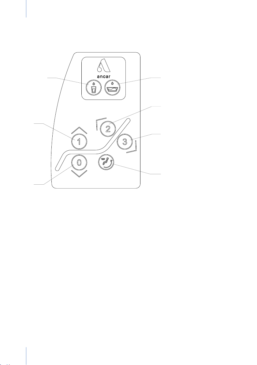
8.7. Auxiliary keypad.
The auxiliary keypad (or assistant keypad) is located on the hose support (Fig. 17).
USER MANUALDENTAL UNIT SD-150 - REV.2 JULY 2020
A
D
E
B
F
G
C
A. Tank and cuspidor water. Timer, 2s-12s.
The cuspidor and basin can be set up to operate in combination or separately.
B. Press and hold: Raises the chair manually.
Press once: Automatic movement -> Free position 1 in the memory.
C. Press and hold: Lowers the chair manually.
Press once: Automatic movement: -> Return to zero.
D. Cuspidor water. Timer, 10s-180s. It is switched off by using the same function.
E. Press and hold: Moves the backrest up manually.
Press once: Automatic movement -> Free position 2 in the memory.
F. Press and hold: Moves the backrest down manually.
Press once: Automatic movement -> Free position 3 in the memory.
G. Returns to cuspidor. The rst press will move the backrest to the cuspidor.
When pressed a second time, the backrest returns to its initial position.
18
Page 21
USER MANUAL DENTAL UNIT SD-150 - REV. 2 JULY
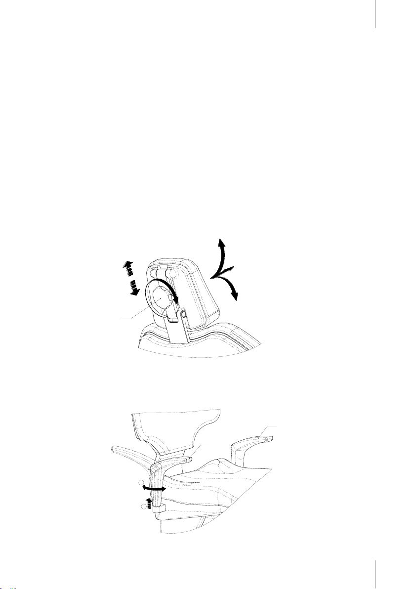
8.8. Headrest
The headrest can easily be moved to the ideal position for the patient's head thanks to its
articulation mechanism, depending on the treatment required. It is easy to adjust along its entire
length, as shown in Figure 18.
OPERATION
- Easy lengthwise adjustment. The part is locked internally to maintain the position.
- The desired angle of the headrest is obtained by rotating part "A". Once the ideal position
of the head is attained, lock the mechanism by turning the “A” handle clockwise.
For comfortable maintenance, the upholstery of the headrest can be easily replaced by
removing it from the frame.
8.9. Optional armrest
The armrest (B) is rotated by pulling it upwards (without removing it from its housing) until the
rotary mechanism unlocks and allows rotation to its end of travel, where it will lock again. To
move the armrest to its initial position again, simply raise it again and push it in until it locks
automatically. (Fig. 19).
170mm
A
The standard armrest (A) is xed in place.
Fig. 18
A
B
Fig. 19
19
Page 22

USER MANUALDENTAL UNIT SD-150 - REV.2 JULY 2020
9. SAFE MOVEMENTS
- The dental chair is equipped with end of travel micro switches at the ends of the seat and
backrest that provide accurate manoeuvring and positioning.
- Motor overload control using integrated thermal protectors. If these sensors are triggered,
wait 15 minutes for the motor to cool.
- Headrest safety is ensured; if pressure is applied on the headrest or it collides with an
obstacle when moved downwards automatically or manually, all chair movements are
stopped (seat and backrest) after raising it previously a few centimetres.
- Chair base safety is ensured; if pressure is applied on the base or it collides with an obstacle
when moved downwards automatically or manually, all chair movements are stopped (seat
and backrest) after raising it previously a few centimetres.
- Hose safety is ensured; if pressure is applied on the arm or it collides with an obstacle when
moved downwards automatically or manually, all chair movements are stopped (seat and
backrest).
-
Regulating pedal safety is ensured; all chair movements (seat and backrest) are blocked
when the regulating lever is activated so work on the patient's oral cavity can be performed
in complete safety. If the chair is moving, it can be stopped by activating the pedal lever
("B", Figure 5).
-
Regulating pedal safety is ensured; automatic movements cannot be entered. Thereby,
unexpected activation due to the sensitivity of the three dimensional movement button is
prevented.
- Keypad (main and auxiliary) safety is ensured; if the chair performs a memorised movement,
it can be stopped by pressing any of the movement keys.
10. CLEANING AND STERILISATION
It is extremely important to use neutral dental products to clean the equipment. Cleaning
products with high contents of chemicals can damage the plastic parts and upholstery.
During cleaning, take care not to wet the equipment excessively, since it houses electronic
components. A variety of dental hygiene specialists offer a wide range of cleaning products to
achieve optimal results.
ANCAR carries out systematic, comprehensive cleaning of its equipment before
shipping with the disinfecting agent ECO-JET1 Spray by Magnolia (Cattani Group).
To clean and disinfect the various parts of the equipment, please refer to:
- The “Hose Support” section.
- Annex 2. “VS300 Suction Valves Kit (Dürr Dental)”.
- Annex 3. "TYP1 Suction System (Metasys)".
- Annex 4. "ECO Suction System (Metasys)".
- Annex 6. “CAS1 combi-separator (Dürr Dental)”.
- Annex 9. "H1 Hygiene System (Metasys)".
- Annex 10. "Minilight Syringe (Luzzani)".
- Annex 12. “Cleaning and disinfecting other parts of the equipment”.
STERILISATION AND AUTOCLAVE.
135°
20
Sterilisation of manual devices must be performed in an autoclave and at an
average temperature of 135ºC. However, for ideal sterilisation, we recommend
following the manufacturer's instructions.
The hoses and hose tray can also be sterilised. Refer to the "Hose support"
section.
Remember that proper maintenance and use of the equipment will prolong its
useful life.
Page 23

USER MANUAL DENTAL UNIT SD-150 - REV. 2 JULY
11. TECHNICAL DATA
Voltage 230V
Frequency 50 Hz
Air pressure 5 Bar
Water pressure 2.8 Bar
Power 900 W
Electrical protection class I
Type of operation Intermittent
Maximum load (patient) 160 Kg.
Maximum instrument tray load 2 Kg.
Electrical Micromotor Instrument 24Vdc / 65 W
Instrument lights Bulbs 3v – 7v / 2.5 W
Ultrasound 24Vac / 35 W.
Polymerising lamp 24Vac / 150 W.
3F Syringe -6F Syringe (optional) 24Vac / 150 W.
Operating lamp (depending on the model) 17 Vac / interval of 9 to 95 VA
Operating lamp (light intensity) Between 3,000 and 50,000 lux
Operating lamp (light beam) 140 x 70 to 180 x 90 cm
Unit class 93/42/EEC Class IIa
Insulation type Type B
Net/Gross unit weight 240 kg. / 310 kg.
Type of dental unit Electro-Pneumatic
Type of installation Permanent
Main fuse T 6.3A / 250V
Movement card fuse, line 24Vac T 32 mA / 250V
Primary transformer fuse, 9015093 PCB T 2A / 250V
Line protection 24Vac (yellow/yellow) Polyswitch RUE600
Line protection 17Vac (red/red) Polyswitch RUE600 + RUE185
Auxiliary outputs 24Vac 4 x hydric box
Auxiliary output 24Vac 1 x connections box
Suction connection 500W / 230V. Relay 20A/250V
Auxiliary connection Potential free contact 250V/5A
Main solenoid valves 24 Vdc
21
Page 24
USER MANUALDENTAL UNIT SD-150 - REV.2 JULY 2020
On request, the hydric unit can be supplied with a drain by gravity or continuous suction system
and with the option of an amalgam separator for wet or dry systems. See the annexes of this
manual to follow each manufacturer's specic instructions.
As shown in Fig. 10, all the components located in the hydric box can be accessed by pressing
on the top of the door to open it.
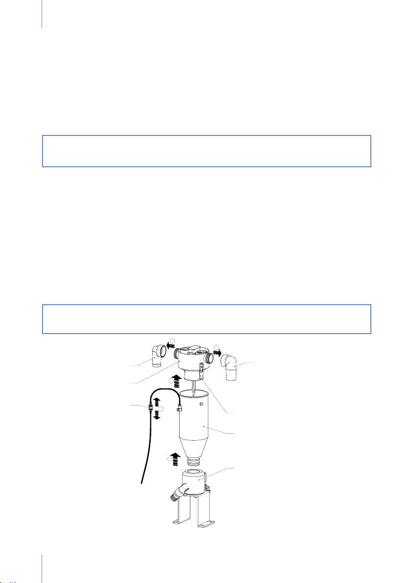
ANNEX 1. CLEANING AND DISINFECTING THE CATTANI
TANK, HOSES AND BASIN
Before opening the door of the hydric box or removing the tank, disconnect the
dental unit from the mains by switching the main switch off. Use appropriate
protection gloves.
Tank, at the end of the work day.
To remove the tank (E), disconnect the switch (A) and extract the two elbow pipes (C) from the
suction hoses. To remove the cover (B), lift and pull gently on the fasteners (D) and pull the
tank upwards (E) to separate the support (F). This can also be cleaned. Place the tank again by
following the instructions in reverse. Use Puli-Jet (Cattani) and water.
Hose circuit, at noon or at night.
Cleaning and disinfection: Use Cattani Pulijet.
Concentration: 50 cL per litre of water. Insert water through each hose.
External hose surfaces, after each treatment.
Disinfectant: Eco-Jet Cattani.
Rinse the tank with water after each treatment.
Hose lter: anti-foam disinfectant.
Use air-purifying tablets for the hose lter.
Caution:
Do not clean with foam-generating detergent. Do not use sodium hypochlorite.
C
B
A
C
D
E
22
F
Fig. 20
Page 25
USER MANUAL DENTAL UNIT SD-150 - REV. 2 JULY
ANNEX 2. VS300 SUCTION VALVES KIT (DÜRR
DENTAL). MAINTENANCE OF THE SUCTION SYSTEM IN
COMBINATION WITH THE CUSPIDOR VALVE
Before opening the door of the hydric box or removing the tank, disconnect the
dental unit from the mains by switching the main switch off. Use appropriate
protection gloves.
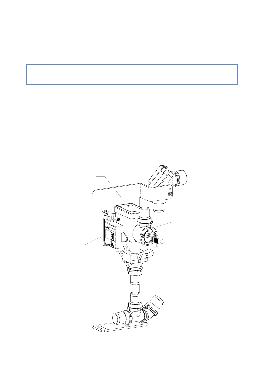
The suction/draining unit (B) is equipped with a lter (C) that requires maintenance. As shown
in the gure, rotate the part (“1”) and then pull it (“2”) outwards gently to remove it.
On the inside there is a control box with a reset button (A).
Refer to the manufacturer's instruction manual that is supplied with the dental unit before
performing maintenance, cleaning or disinfection, to become familiar with its operation or in
case of doubt. Always use hygiene and disinfecting products recommended by the manufacturer.
B
A
C
Fig. 21
23
Page 26
USER MANUALDENTAL UNIT SD-150 - REV.2 JULY 2020
A
ANNEX 3. TYP1 SUCTION SYSTEM (METASYS)
Before opening the door of the hydric box or removing the tank, disconnect the
dental unit from the mains by switching the main switch off.
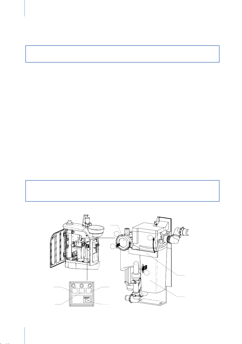
The lter (A) requires maintenance: turn the (“2.1”) and then remove (“2.2”).
To access the separation and sedimentation component (C) the closing ange (B) has to be
rotated upwards (“1.1”) to remove it towards the front (“1.2”).
The control keypad can be accessed from the outside on the side of the hydric box.
Control led (D): ready for service. Green light on: connection with the mains.
Control led (F): centrifuge malfunction. Flashing red light: malfunction! Turn off the main
switch and turn it on again after a short pause.
Control led (E): lling level of the container (C). The bright yellow light with buzzer sounding
can be switched off with the reset key (G). This alerts that the container is 95% full. It is
recommended to change the container.
When the light (E) remains bright yellow and the buzzer cannot be switched off, this
indicates that the container is 100% full and has to be changed. It is impossible to continue
working. The suction valve is locked.
Reset - alarm key (G).
Refer to the manufacturer's instruction manual that is supplied with the dental unit before
performing maintenance, cleaning or disinfection, to become familiar with its operation or in case
of doubt. Always use hygiene and disinfecting products recommended by the manufacturer.
Removing the full container:
Wear protective gloves. Do not touch the contents of the container. For technical
and hygienic reasons, the container is designed for a single use.
2.1
2.2
1.1
B
D
1.2
E
C
F
24
G
Page 27
USER MANUAL DENTAL UNIT SD-150 - REV. 2 JULY
ANNEX 4. ECO SUCTION SYSTEM (METASYS)
Before opening the door of the hydric box or removing the tank, disconnect the
dental unit from the mains by switching the main switch off.
A
B
Fig. 22
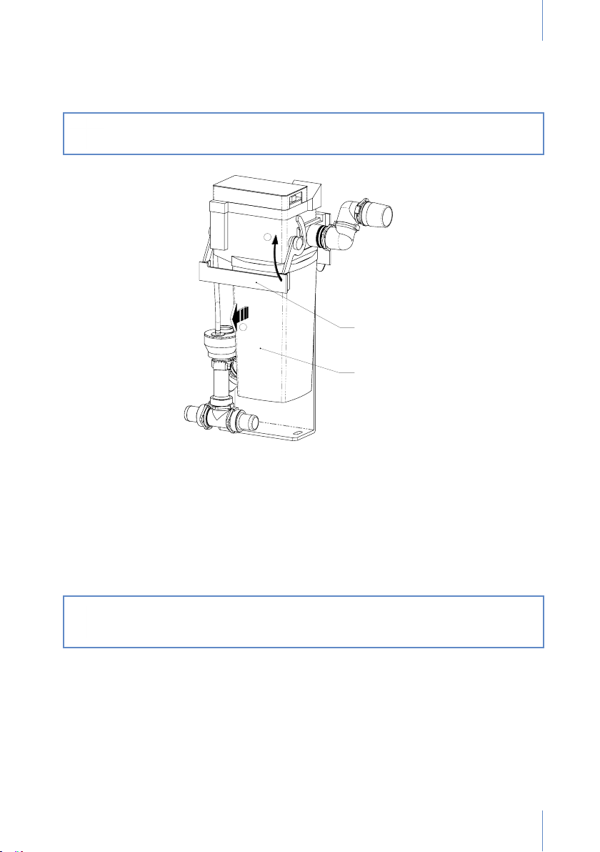
This is an automatic air/water separator equipped with a heavy particles collector.
To access the separation and sedimentation component (B), turn the closing ange (A) up (“1”)
to pull it out ("2").
Refer to the manufacturer's instruction manual that is supplied with the dental unit before
performing maintenance, cleaning or disinfection, to become familiar with its operation or in case
of doubt. Always use hygiene and disinfecting products recommended by the manufacturer.
Removing the full container:
Wear protective gloves. Do not touch the contents of the container. For technical
and hygienic reasons, the container is designed for a single use.
25
Page 28
USER MANUALDENTAL UNIT SD-150 - REV.2 JULY 2020
ANNEX 5. SELF WATER SYSTEM KIT
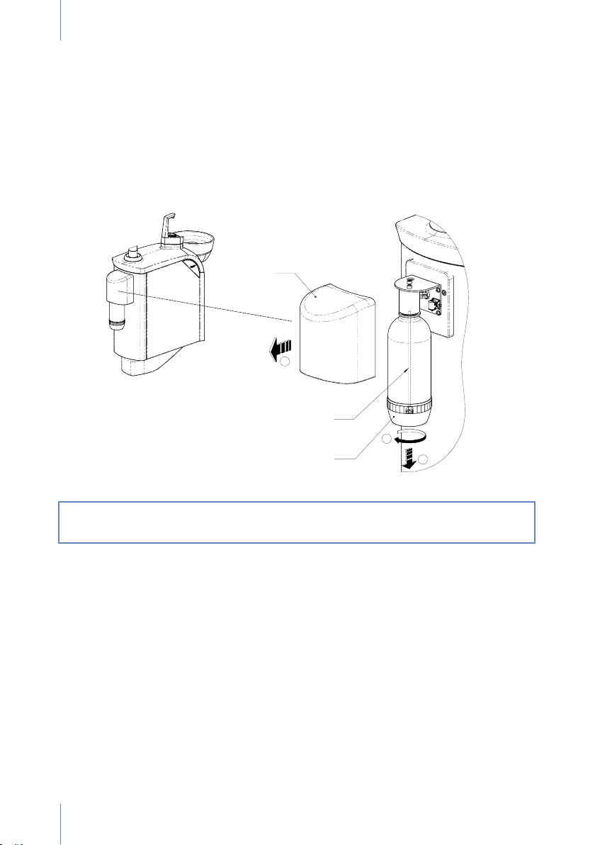
Access the bottle (1-litre capacity) from the outer part of the hydric unit by removing the cover
(A) outwards ("1").
This is an independent mains water system; the air regulator is normally sealed.
To ll with water unscrew (“2”) the bottle (C) and pull down (“3”). There is a safety pressure
switch on the inside that is activated automatically.
Please replace the bottle (C) gently and be careful with the internal tube (B).
A
B
C
Important recommendations
If the Self Water System is not going to be used for a long period of time, during weekends,
holiday periods, etc., the liquid lines of the instruments and syringe should be bled and
ventilated. This will help to prevent clogging of liquids in the water lines.
26
Fig. 23
Page 29
USER MANUAL DENTAL UNIT SD-150 - REV. 2 JULY
C
ANNEX 6 CAS 1 COMBI-SEPARATOR (DÜRR DENTAL)
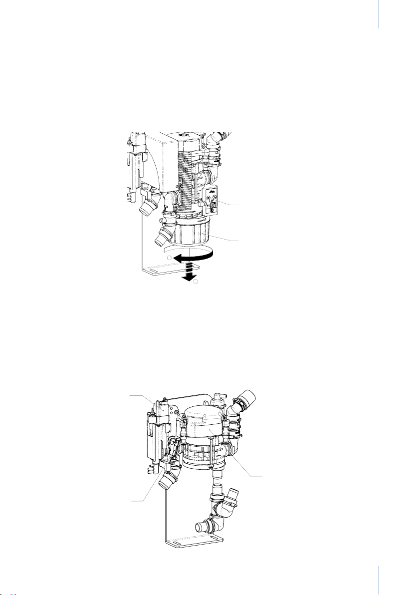
The control panel is located on the inside (A).
The tank (B) should be cleaned. To remove it, unscrew (“1”), but before extracting it (“2”), note
that there is a part that measures the level of the amalgam elements contained that protrudes
from the bottom.
A
B
Fig. 24
ANNEX 7. CS 1 SEPARATOR(DÜRR DENTAL)
This system is designed for use in dry suction systems. It does not retain any elements; all the
liquid passes through an integrated pump and is released in the drain.
The pump unit (A) works by compressor suction, which is activated when the hose is pulled.
This opens the cut-off valve (B). The rinsing unit (C) provides unit suction with permanent
supply of fresh water to ensure that the device does not operate in dry conditions.
Fig. 25
A
B
27
Page 30
USER MANUALDENTAL UNIT SD-150 - REV.2 JULY 2020
ANNEX 8. WATER DECONTAMINATION: WEK (METASYS)
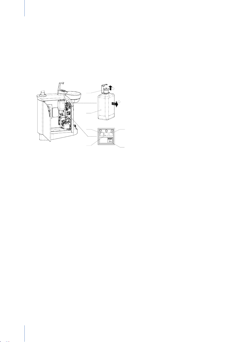
The bag of product (B) is inside the mixing system. The design allows the water to arrive after
a distance of free fall, thanks to which the separation between the WEK system and the supply
of water from the mains guarantees compliance with the DVGW standard. It is impossible for
non-contaminated water or water containing chemical products to return to the water supply.
Open the door to access the unit controls. Pilot light C: ready for use (green), E: malfunction
(red), D: disinfection indicator (yellow). Alarm key - RESET (Alarm - Reset) F.
A
Fig. 26
B
C
E
CHANGING THE BAG CONTAINING GREEN&CLEAN WEK
Once the bag is empty, the green and yellow leds will light up and the alert will sound. If the bag
cannot be replaced immediately, press the RESET key to deactivate the signal. The doctor's
work will not be interrupted. In any event, an alert will sound periodically. Remove the bag (“1”)
by pulling gently on the fastener. Then remove the lid (A) upwards (“2”). The tube connecting
the bag will be removed with it. The removable part (lid and tube) is reused with the new bag.
After removing the screwed lid of the new bag of chemical product, the tube has to be inserted
again and the lid fastened underneath by pressure.
The bag of the tank must be installed in the equipment immediately afterwards, ensuring that
the tube is fastened over the connection for the chemical product.
SUPPLEMENTARY PROGRAMS
Automatic emptying: To empty a device that is being used, press the RESET key (F) for 8
seconds (the C led will ash) until a second beep is heard. The C led will ash slowly. The
stock reserves and pressurised tank will be empty when no more water is released from the
instrument and/or the drain ller. The WEK system can be stopped again or reactivated by
pressing for 8 seconds on the RESET key (F).
Intensive decontamination: To increase the concentration of chemical product, simply press
on the RESET key for 4 seconds (the C led will ash) until a beep is heard. During this process,
the C led remains on and the D led ashes. After intensice decontamination, the D led switches
off and a short vibrating signal remains, indicating that the WEK system is ready for normal
operation.
D
F
28
Page 31
USER MANUAL DENTAL UNIT SD-150 - REV. 2 JULY
ANNEX 9. H1 HYGIENE SYSTEM (METASYS)
Do not use any additional cleaning or disinfecting product for the suction
installation in treatment areas where an H1 hygiene system has been installed.
There is a risk of harmful chemical interactions due to the combination of
different chemical products.
CONTROL KEYPAD
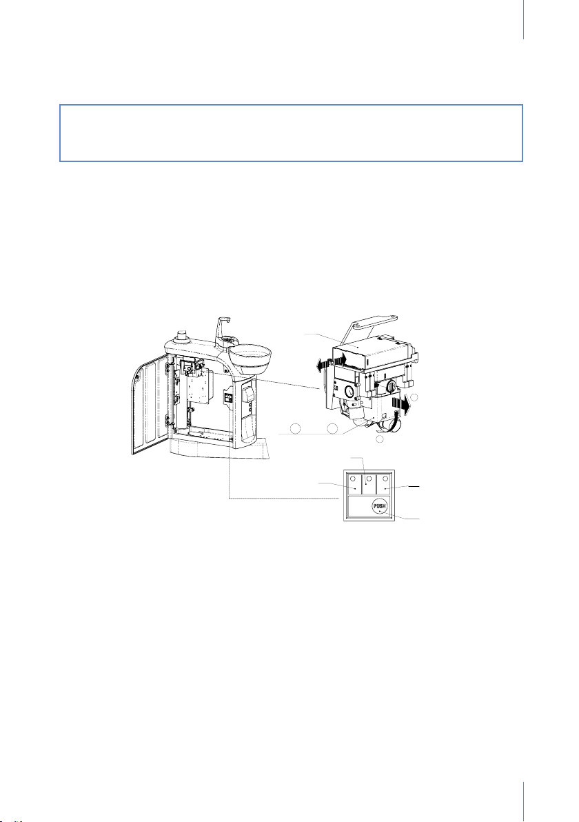
The control keypad can be accessed from the outside on the side of the hydric box.
Led (D): malfunction. A ashing red signal and beep that sounds up to 5 times each time
the suction hoses are lifted. Hygiene system out of service, but suction is available: contact
a technician.
Led (E): tank empty. Yellow signal and 1 beep each time the suction hoses are lifted:
replace cartridge A.
Led (D): program working. When it is green: ready to work. Green light ashes slowly: rst
wash program working. Green light ashes quickly: special wash program working.
Start-up key for the special wash program (G): Activate by pressing the "Push" key.
A
B 1 ; C 2
Fig. 27
E
D
F
G
MAINTENANCE
Continuous washing of the lter screen: Pull on the container clip (B) downwards (“1”).
Remove the container from the lter (C) by pulling horizontally (“2”). Pull the lter screen up (the
lter has to be placed in position again by taking the steps in reverse).
Pour the remains of the amalgam in the container provided for that purpose.
It is recommended to replace the lter screen every 2 to 3 months.
If suction power drops, check for perforations in the lter screen.
After sterilising, do not forget to grease the seals with vaseline!
Replacing the cartridge (A): The yellow led ashes (E) on the control panel and a beep
sounds, indicating that the tank is empty and has to be replaced.
Disconnect the main switch of the unit. Simply press on the front of the cartridge to open the
latch and place the cartridge in its replacement position. Then remove the cartridge from the
equipment horizontally.
29
Page 32

USER MANUALDENTAL UNIT SD-150 - REV.2 JULY 2020
AUTOMATIC CLEANING PROGRAM
First Wash
Duration: approximately 2 minutes. Led F will ash slowly.
Start-up: press on the main switch of the treatment unit.
Function: preparation of later treatments with a higher dose of disinfectants.
Permanent Washing Cycle
Led F stays on.
Duration: from the time the suction hose(s) are lifted to when they are placed again.
Start-up: Lifting at least one suction hose.
Function: To prevent the formation of sediment by washing, disinfection and foaming of the
suction system by periodic dosing of chemical products.
Special Washing Program
The F led will ash quickly. Duration: approximately 5 minutes.
Start-up: by pressing the "Special washing program" key.
Function: if it is necessary to clean and disinfect the suction system after prolonged use of
suction. It is recommended to use the program at least once a day and after prolonged use of
suction.
ANNEX 10. MINILIGHT SYRINGE (LUZZANI)
OVERVIEW
The minilight syringe is an instrument used exclusively in dentistry, created to introduce air and
water (separately or together, at ambient or body temperature) to maintain the operating eld
clean and dry.
GENERAL FEATURES
The minilight syringe is designed following the most modern ergonomic properties to ensure
ease of use, immediate cleaning and sterilisation. Both the tip and the grip can be easily
removed to facilitate perfect disinfection and sterilisation in an autoclave at 135ºC. Grips are
available in a variety of shapes and colours, depending on the needs of the dentist; both curved
or straight. The air and water can be heated to body temperature to prevent patient discomfort
due to the entry of air and water at ambient temperature.
MODELS
Models differ, depending on the number of features available:
- 3F water / air / cold spray
- 5 cold water / cold and hot air / cold and hot spray
- 6F water / air / cold and warm spray
- A only air or only water
- L with light
The version of the minilight syringe is shown at the rear. Different grips can be mounted on any
version indistinctly: curved in techno-polymer, straight in stainless steel.
CE MARKING
All products carry the CE marking.
30
Page 33

USER MANUAL DENTAL UNIT SD-150 - REV. 2 JULY
MANUFACTURING BATCH
Each product is identied with an internal number placed at the end that identies the exact
production batch it belongs to. This number indicates the period of manufacture associated
with the control card.
WARRANTY
The product is guaranteed by our company for up to 12 months after delivery. Any unauthorised
changes or manipulation will automatically render the warranty void. Therefore, the company
shall not be liable for damage to persons, animals or objects due to poor manipulation. The
competent court in the event of discrepancies is the Court of Milan, Italy.
TECHNICAL CHARACTERISTICS
Type B, Insulation Class II, Intermittent operation: 10 seconds ON, 20 seconds OFF.
ITEM 6F 5F 3F
SUPPLY VOLTAGE VAC 24 24 ***
ELECTRICAL CONSUMPTION A 4.3 0.7 ***
MAX. ELECTRICAL POWER W 103 0.7 ***
MAX. WATER PRESSURE BAR 2.5 2.5 2.5
MAX. AIR PRESSURE BAR 4.5 4.5 4.5
MAX. AIR FLOW Nl/min 10 10 10
MAX. WATER FLOW Cc/min 110 110 110
INSTALLATION
Only a technician authorised by Antoni Carles can connect the equipment.
NORMAL USE
- To supply the operating eld with cold water, simply press the push button on the left of the
grip.
- To supply the operating eld with cold air, simply press the push button on the right of the
grip.
- To supply cold air and water (spray) simultaneously, simply press the two push buttons on
the grip at the same time.
- To supply the operating eld with hot water, simply turn the switch at the base of the grip to
the right (the green indicator will light up) and press the push button on the left of the grip
(only versions 6F and L).
- To supply the operating eld with hot air, simply turn the switch at the base of the grip to the
right and press the push button on the right of the grip (only versions 6F and L).
- To supply the operating eld with a combination of hot air and water (spray), simply turn the
switch at the base of the grip to the right and press the two push buttons on the grip at the
same time (only versions 5F, 6F and L).
Note: The switch is used to select the cold and hot functions The air and water are heated at
the time of use. Therefore, the switch can be left in the "On" position without cause any problem
or danger.
31
Page 34

USER MANUALDENTAL UNIT SD-150 - REV.2 JULY 2020
CLEANING AND STERILISATION
After each intervention, the syringe should be cleaned and sterilised to guarantee
135°
maximum hygiene. Do so by taking the following steps:
- Remove the tip (unscrew the nose-tip terminal) and/or the entire grip
(by pressing the button located at the bottom of the same and pressing
upwards).
- Clean any stains with a cloth.
- Place in an autoclave with steam at 135ºC for 20 minutes.
MAINTENANCE
The equipment does not require any specic maintenance, except for the normal cleaning and
sterilisation described in the section above. Never lubricate the syringe, as this could cause
irreparable damage to the device.
SURFACES AND COMPONENTS
The product does not contain hazardous or toxic-harmful components, nor is it in contact with
these types of products during its manufacturing cycle.
32
Page 35
USER MANUAL DENTAL UNIT SD-150 - REV. 2 JULY
ANNEX 11. OPTIONAL COMPONENTS
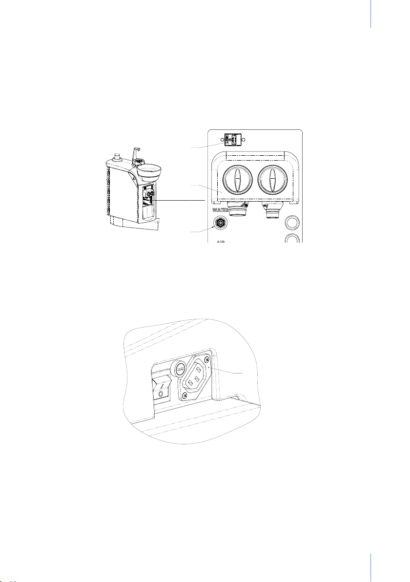
AUXILIARY AIR AND WATER OUTLETS / USB INPUT
In the hydric unit it is optional to have a rapid water (C) and air (D) outlet, as well as a USB input
(A) for end-to-end communication, the other end of which will pass through the dental unit. (B)
is the collector of the hose suction tubes, referred to in section 8.6.
Fig. 28
A
B
C
AUXILIARY POWER OUTPUT
Along with the main ON/OFF switch, an auxiliary 230Vac / 50W (A) output can be added.
A
Fig. 29
33
Page 36

USER MANUALDENTAL UNIT SD-150 - REV.2 JULY 2020
ANNEX 12. CLEANING AND DISINFECTION OF OTHER
EQUIPMENT PARTS
Cleaning and disinfection
Carry out the operations with the device disconnected from the mains.
Do not ood or wet the equipment with water.
Do not use household or foam detergents for disinfection.
Cleaning the upholstery
Clean regularly with a soapy solution.
Cleaning the polyurethane (unit base cover, upholstery frames, lifting system covers)
Polyurethane parts must be cleaned with a cloth soaked in water and soap.
Do not use solvents, detergents or abrasive agents to remove difcult stains.
Clean regularly.
Clean and disinfect the outer metal parts (except instruments)
Use any product with antimicrobial, fungicide, sporicide and virucide properties compatible
with the medical sector.
Cleaning and Disinfecting the Column Arm and Lamp
Disinfection by spraying. Do not spray on hot surfaces.
Wait for the head of the dental lamp to cool before spraying.
For these parts, regularly use a disinfectant with at least antimicrobial and fungicide activity.
Use a cloth moistened in water to clean the lamp, the front and the handles. Clean the reecting
mirror with a dry cloth.
Refer to the manufacturer's instructions.
Cleaning and Disinfection of the Basin-Cuspidor
Use the disinfectants recommended by Cattani or Metasys. See Annexes I and II.
Cleaning and disinfection of the hydric box
Regular cleaning and disinfection: use a disinfectant with antimicrobial, fungicide, virucide and
sporicide properties.
Cleaning and disinfection of the instrument tray, auxiliary tray and hoses
Cleaning and disinfection: after each treatment use a disinfectant with antimicrobial, fungicide,
virucide and sporicide properties.
34
Page 37

USER MANUAL DENTAL UNIT SD-150 - REV. 2 JULY
ANCAR recommends the use of the reloadable BODE X-WIPES dispenser for
professional cleaning and disinfection. Indicated for all BODE surface disinfectants in
concentrations that act for 1 hour or less.
35
Page 38

USER MANUALDENTAL UNIT SD-150 - REV.2 JULY 2020
ANNEX 13. SAFETY OBSERVATIONS
GENERAL PRECAUTIONS
Refer to all the necessary manuals. Keep all the manuals - dental unit, chair, instruments, lamp
and additional kits - in a safe place for future reference.
Read all the annexes in this manual before starting up the unit.
First start-up: perform a cleaning protocol of the water circuit by rinsing all the water conduits of
the instruments and hydric box with a solution of water and disinfectant.
Disconnect the equipment from the mains at the end of the work day by switching off the main
switch.
If the equipment is not going to be used for a period of time, close the main air and water valves
and disconnect it from the mains.
If the equipment is equipped with an amalgam separation system, please do not throw away
the collection tank once it is full, or empty the tank in the garbage or down the drain to reuse it.
Contact the delegation of the separation system manufacturer or our Sales Department. Refer
to Annex II.
Do not replace the fuses on your own. Contact a technician authorised by Antoni Carles, S.A.
through our Sales Department.
Contract an authorised maintenance service. This will increase your condence and prolong
the useful life of the equipment. Contact our Sales Department.
Inspect the equipment regularly to ensure that there are no air or water leaks at the base of
the dental unit connections and that the area is kept clean, dry and free of rust or electrolysis.
Do not use the unit to support or hold furniture or other materials. Do not lean on the hydric box.
Do not sit on the hydric box support. Do not hang from the lamp. The equipment must only be
used by qualied staff.
SAFETY MEASURES FOR THE DENTAL LAMP
Move the lamp only by the handles. Do not move it by gripping the head.
Do not place marks on the protection screen.
Do not force the maximum and minimum power regulators.
ELECTRICAL SAFETY MEASURES
It is not advisable to use mobile phones near the dental unit. Follow hospital premises standards.
If the lamp is overloaded, the thermal protection integrated in the 24 Vac line may interrupt
operation. Wait 15 minutes for the line to reset. If the anomaly continues, call the technical
service.
If the instrument and hydric unit line is overloaded, the thermal protection integrated in the 24
Vac line may interrupt operation. Wait 15 minutes for the line to reset. If the anomaly continues,
call the technical service.
If the chair is overloaded, the integrated thermal protection of one of the motors may be
triggered and interrupt the manoeuvre. Wait 15 minutes for the motor to reset. If the anomaly
continues, call an authorised technical service.
Do not add additional multiple sockets or extensions to the auxiliary sockets available in the
electronic cards.
OBSERVATIONS ON ELECTROMAGNETIC INTERFERENCE
Electronic regulation instruments can cause harm to patients with pace makers and/or ear
prostheses due to electromagnetic interference.
The patient may be at risk due to the proximity of electrical scalpels and other electric/electronic
devices that can cause electromagnetic or other types of interferences, causing malfunction of the
unit. It is advisable to disconnect the dental unit from the power supply before using these devices.
36
Page 39
USER MANUAL DENTAL UNIT SD-150 - REV. 2 JULY
Risk of intervention with autonomous devices (e.g., motor for implants). Disconnect the
power of the dental equipment to prevent indirect movements caused by malfunctions and/or
unexpected activation of movement controls.
This equipment complies with standard EMC (EN 60601-1-2:2007 + AC:2010).
a) This electrical-medical device requires special precautions to be taken as set forth in the
EMC standard and should be installed and placed according to the EMC information included
in the attached documents.
b) Portable RF communication equipment (e.g., mobile phones) may affect medical devices.
c) Accessories such as transducers, cables, etc., other than those specied or supplied by the
manufacturer as spare parts may increase or reduce the immunity of this device.
d) This device should not be used in the proximity of other equipment. If proximity to other
equipment is necessary, proper operation of the nal conguration system must be checked.
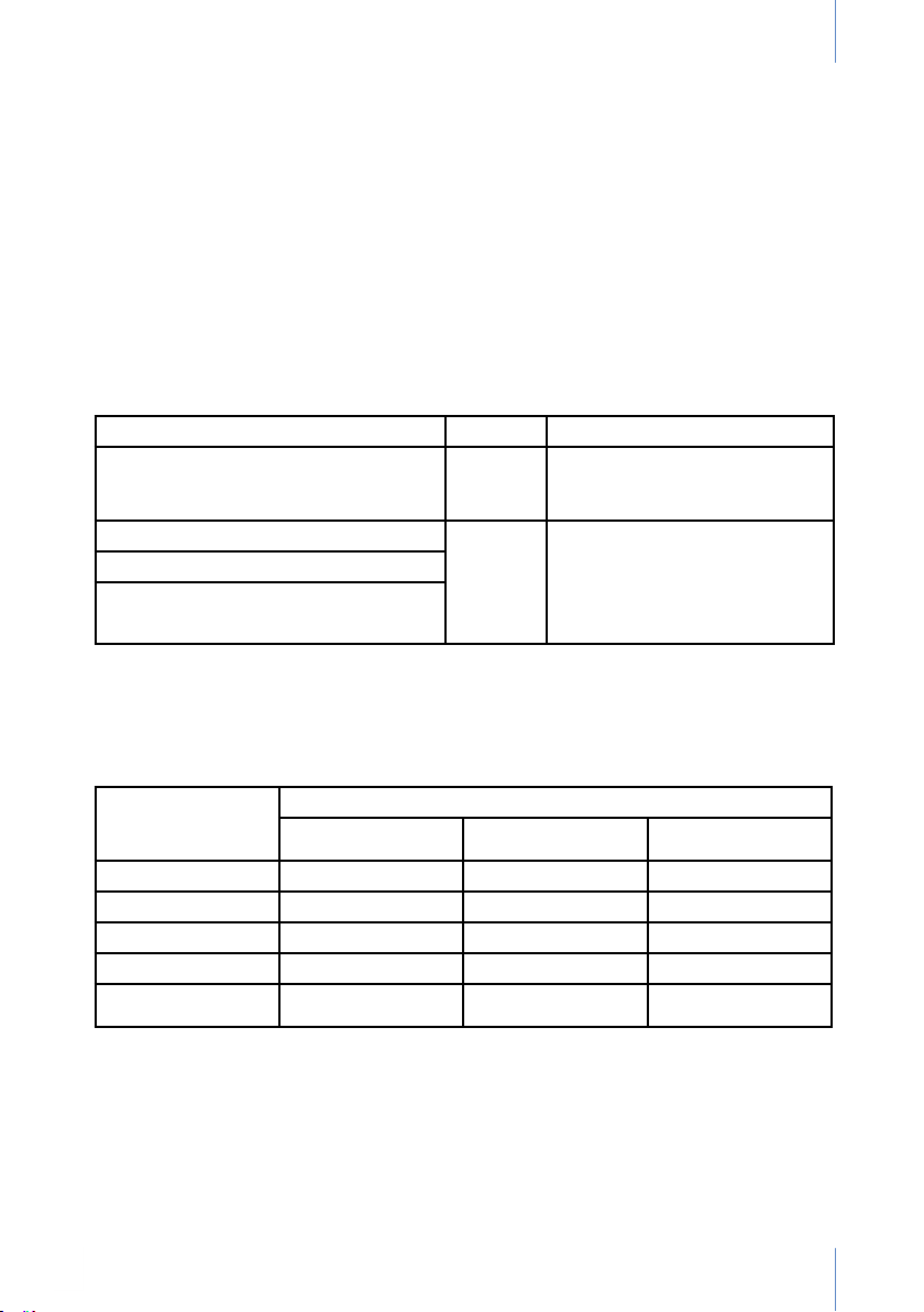
Electromagnetic emissions
Test Category Observations
Radiated radio frequency (30-1000 MHz)
Conducted in direct current (0.15-30 MHz)
Conducted in alternate current
Voltage swings
Current harmonics
Recommended distance between radio frequency communication systems, mobile phones
and dental equipment.
The dental unit is designed to be used in an electromagnetic environment where radio
frequency interferences are controlled. The user of the dental unit can prevent EMC interference
by keeping the transmitting devices at a minimum distance, as recommended, depending on
the maximum output.
Class B Complies with requirements of
domestic locations with regard to
nearby equipment.
Low emissions, adequate for
Complies
use in any location, including
domestic locations. Not likely to
cause interferences with nearby
electronic devices.
Nominal maximum
output of the
transmitter in [W]
Separation, depending on transmitter frequency, in [m]
150kHz – 80 Mhz 80 Mhz – 800 MHz 800 Mhz – 2.5 GHz
0.01 0.12 0.12 0.23
0.1 0.38 0.38 0.73
1 1.2 1.2 2.3
10 3.8 3.8 7.3
100 12 12 23
These instructions may not be applicable if electromagnetic propagation can be absorbed or
reected from structures, objects or persons.
37
Page 40
USER MANUALDENTAL UNIT SD-150 - REV.2 JULY 2020
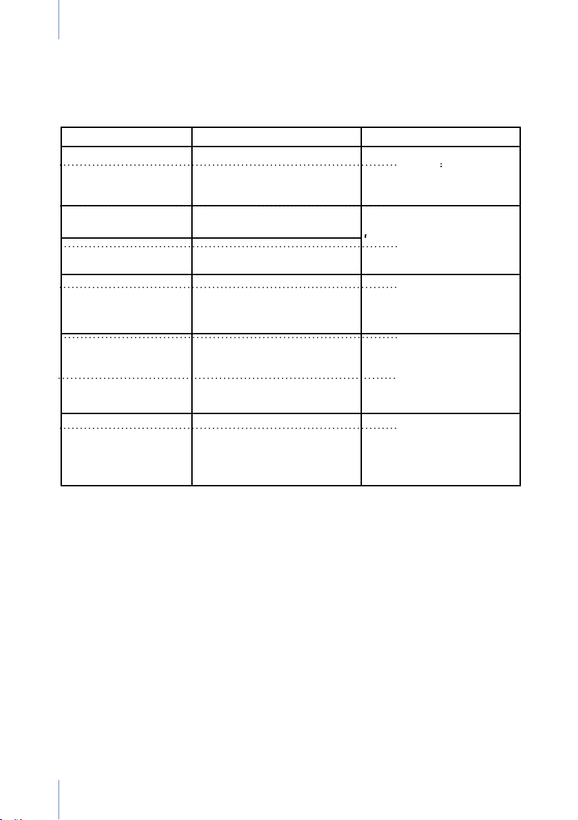
Electromagnetic immunity
Test Category Comments
Electrostatic discharge Discharge into the air: 2, 4, 8 kV
Contact discharge: 2, 4, 6 kV
Rapid transients (burst
immunity)
Transient overvoltages Common mode 0.5, 1, 2 kV
Immunity versus low
frequency magnetic
elds
Current injections 3V rms (150 kHz – 80 Mhz)
Voltage swings Brief voltage interruptions and
2 kV I/O ports The quality of the electrical
Differential mode 0.5, 1 kV
3 A/m The power and frequency
3 V/m (80MHz – 2.5 GHz)
Signal and control ports and
AC/DC power, access by
grounding terminal.
drops.
OBSERVATIONS ON INFLAMMABLE ANAESTHETIC MIXTURES
Do not use the unit/chair in the presence of inammable anaesthetic gas mixtures with oxygen or nitrogen
protoxide.
Improved performance with
wood and ceramic materials.
With synthetic materials,
humidity > 30%
network must be standard
commercial quality or quality
for hospital conditions.
of magnetic elds must be
characteristic of a typical
location.
Recommended distance
1.2 √P (up to 800MHz)
2.3 √P (from 800MHz)
P is the maximum output
power of the transmitter.
If the user requires
continuous operation without
electrical power outages, it
is recommended to use an
uninterruptible power supply.
ANNEX 14. SYMBOL DEFINITIONS
38
Page 41

USER MANUAL DENTAL UNIT SD-150 - REV. 2 JULY
39
Page 42

Volta dels Garrofers, 41-42 Polígono Industrial “Els Garrofers”
www.ancar-online.com / e-mail: [email protected]
Antoni Carles, S.A.
08340 Vilassar de Mar (Barcelona-SPAIN)
Tel. (34) 93 754 07 97 Fax (34) 93 759 26 04
DENTAL UNIT SD-150 - REV. 2 JULY 2020
Subject to design and/or specications changes
without prior notice. Made in Europe.
0197
 Loading...