

Page 1
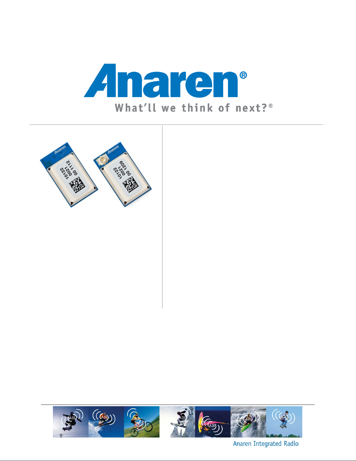
Anaren Integrated Radio
A20737x User’s Manual
Release Date: 09/25/14
Page 2

THIS PAGE INTENTIONALLY LEFT BLANK
Page 3

iii
USER’S MANUAL
Models A20737A and A20737C
Contents
1. Overview .......................................................................................................................................................... 5
1.1. A20737A ..................................................................................................................................................... 5
1.2. A20737C ...................................................................................................................................................... 5
1.3. Features....................................................................................................................................................... 6
1.4. Theory of Operation.................................................................................................................................. 6
1.5. Applications ............................................................................................................................................... 8
2. Approvals and Usage ..................................................................................................................................... 9
2.1. Product Approvals .................................................................................................................................... 9
2.1.1. USA (Federal Communications Commission, FCC) ........................................................................... 9
2.1.1.1. FCC Labeling Requirements .................................................................................................. 9
2.1.1.2. End User Manual ................................................................................................................... 10
2.1.1.3. RF Exposure ............................................................................................................................ 10
2.1.2. Canada (Industry Canada, IC) .......................................................................................................... 10
2.1.2.1. IC Labeling Requirements .................................................................................................... 12
2.1.2.2. RF Exposure ............................................................................................................................ 14
2.1.3. Europe (Conformité Européenne, ) ............................................................................................... 14
2.2. Potential Interference Sources ............................................................................................................... 15
2.2.1. WLAN ............................................................................................................................................... 15
2.2.2. Classic Bluetooth ............................................................................................................................... 15
2.2.3. Microwave ovens ............................................................................................................................... 16
2.2.4. Other Interference ............................................................................................................................. 16
2.3. Approved Usage ..................................................................................................................................... 16
2.3.1. USA and Canada............................................................................................................................... 16
2.3.2. Europe ............................................................................................................................................... 17
2.3.3. Bluetooth ........................................................................................................................................... 17
3. Electrical Characteristics .............................................................................................................................. 18
3.1. Absolute Maximum Ratings .................................................................................................................. 18
3.2. Operating Conditions ............................................................................................................................. 19
3.3. Pin Out ...................................................................................................................................................... 19
3.4. Recommended Layout (dimensions in mm) ...................................................................................... 22
3.5. Power Supply Considerations ............................................................................................................... 23
4. Mechanical and Process ................................................................................................................................ 24
4.1. Radio Module Details (dimensions in mm) ........................................................................................ 24
4.1.1. A20737A ........................................................................................................................................... 24
4.1.2. A20737C ........................................................................................................................................... 24
4.2. Packaging Details (dimensions in mm) ............................................................................................... 25
4.2.1. Matrix Tray Packaging ..................................................................................................................... 25
4.2.2. Tape-Reel Packaging ......................................................................................................................... 25
4.3. Soldering................................................................................................................................................... 26
4.3.1. Manual Mounting Procedure ........................................................................................................... 26
4.3.2. Automated Mounting Procedure ...................................................................................................... 27
Page 4

Page 5

A20737x – User’s Manual Page 5 of 30
Release Date 09/25/14
1. Overview
The A20737A and A20737C modules are surface mount 2.4GHz RF transceivers incorporating
Bluetooth® SMART technology per the Bluetooth v4.0 core specification (Bluetooth SMART
technology is formerly known as Bluetooth Low Energy or BLE). The A20737A has an integral
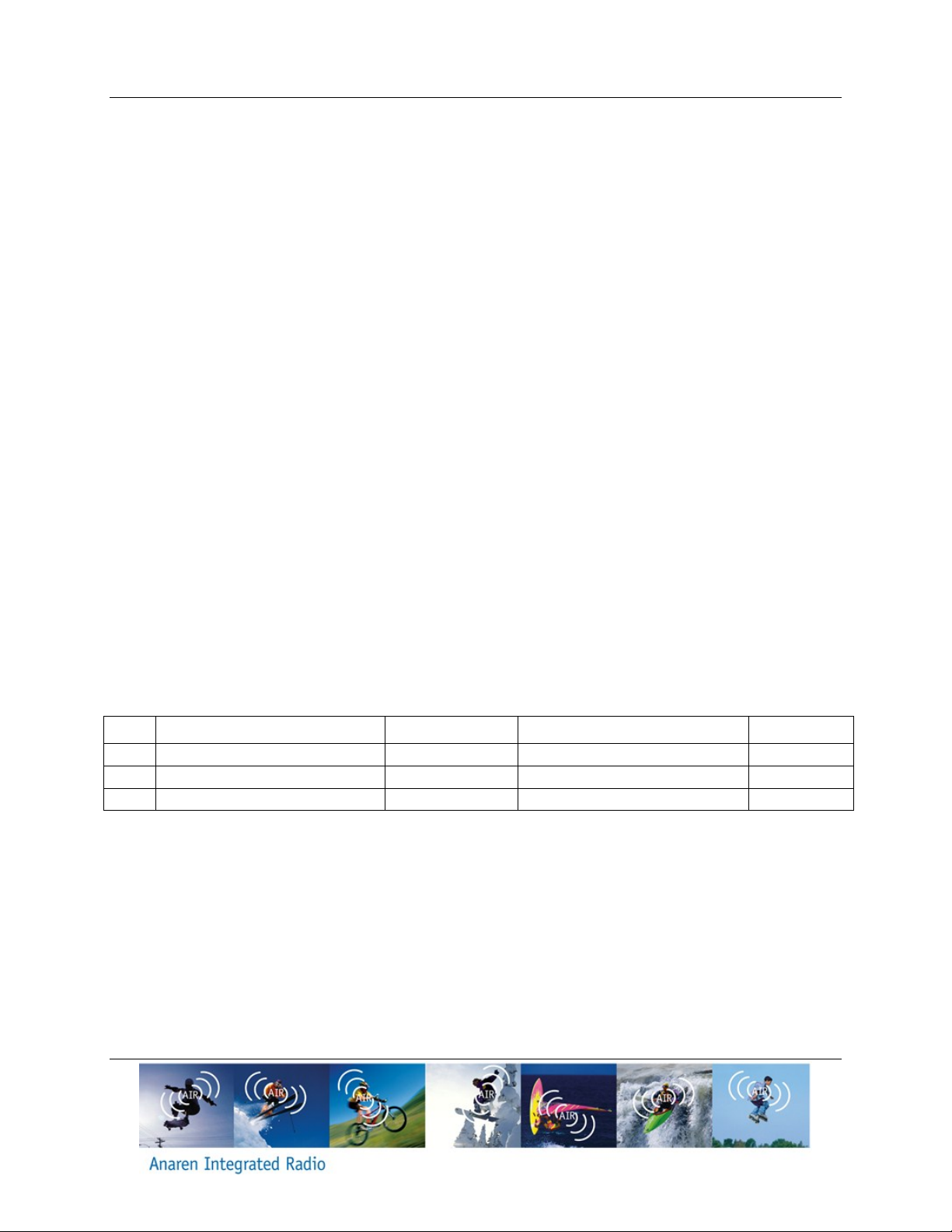
antenna, whereas the A20737C utilizes an external antenna through a U.FL connector (see
Table 1). These modules incorporate a crystal, 512-Kbit EEPROM, the required RF matching
and filtering for regulatory compliance as well as filtering for noise reduction and sensitivity.
They operate in the global unlicensed 2.4GHz ISM/SRD frequency band. The modules are ideal
for achieving low power, long range wireless connectivity without having to deal with extensive
protocol, RF, antenna design and regulatory compliance, and provide quick time to market.
They are 100% tested to provide consistent performance.
The A20737A and A20737C modules have received regulatory approvals for modular devices in
the United States (FCC), Canada (IC) and Europe (ETSI). The modular approval allows the end
user to place either an A20737A or an A20737C with an approved antenna inside a finished
product without having to perform costly regulatory testing for an intentional RF radiator. Section
2.3 has information on the requirements for the end user/integrator to fulfill in order to use the
modules without intentional radiator regulatory testing.
The A20737A and A20737C are based on the BCM20737 SoC transceiver from Broadcom. The
BCM20737 combines the excellent performance of a leading RF transceiver with an integrated
ARMR CortexTM-M3 based microcontroller core. All control lines are provided at module level for
full control of the operation. Please see the user’s guide for BCM20737 (www.broadcom.com)
for how to operate, program and control these modules.
The A20737A and A20737C modules are available loaded with “BLE Stack” firmware from
Broadcom and 512-Kbit EEPROM for customer applications.
The A20737A and A20737C modules measure 11 mm x 13 mm x 2.5 mm. The modules are
footprint compatible with each other.
1.1. A20737A
The A20737A has an integral antenna, providing high efficiency and near omni-directional
radiation pattern. This approach offers the lowest system cost when the application allows
collocation of radio and antenna. See Figure 6 - Figure 7 for more information on antenna
location and enclosure considerations.
1.2. A20737C
The A20737C has a compact antenna connector that allows for locating the antenna away from
the module due to form/function or in order to exit a metal enclosure. Please see Table 1 for a
list of approved antennas.
Page 6

Page 6 of 30 A20737x – User’s Manual
Features:
2.4 GHz Bluetooth Smart technology
1.7 to 3.6 V operation
Integrated ARM Cortex-M3 based
microprocessor core
512-Kbit EEPROM for applications
Programmable output power control
18 General Purpose I/O Pins
Low current consumption (25 mA in RX
and, 20mA @ 3 dBm)
Excellent receiver sensitivity, -94 dBm
average in BLE HGM with <1% PER.
Infrared modulator
10-Bit auxiliary ADC with nine analog
channels
Support for secure OTA
Integrated LDO
RoHS Compliant
Shielded package
LGA Footprint
Very Small package size:
11mm x 13mm x 2.5mm
Approximate weight 0.5 grams
Benefits Summary:
Operating temperature-30 oC to +85 oC
100% RF Tested in production for
repeatable performance
No RF engineering experience
necessary
No protocol experience necessary
Only requires a 2 layer Host PCB
implementation
FCC 15.247, IC RSS-210 and IC RSS-
Gen certified.
Compliant with ETSI EN 300 328
No regulatory “Intentional radiator”
testing required for integrating module
into end product. Simple certification
labeling replaces testing.
Release Date 09/25/14
1.3. Features
1.4. Theory of Operation
The A20737A and A20737C modules operate in the global 2.4 GHz ISM/SRD frequency band.
They incorporate Bluetooth SMART technology and can be used in a variety of networks that
use this protocol. No other modes/protocols are supported.
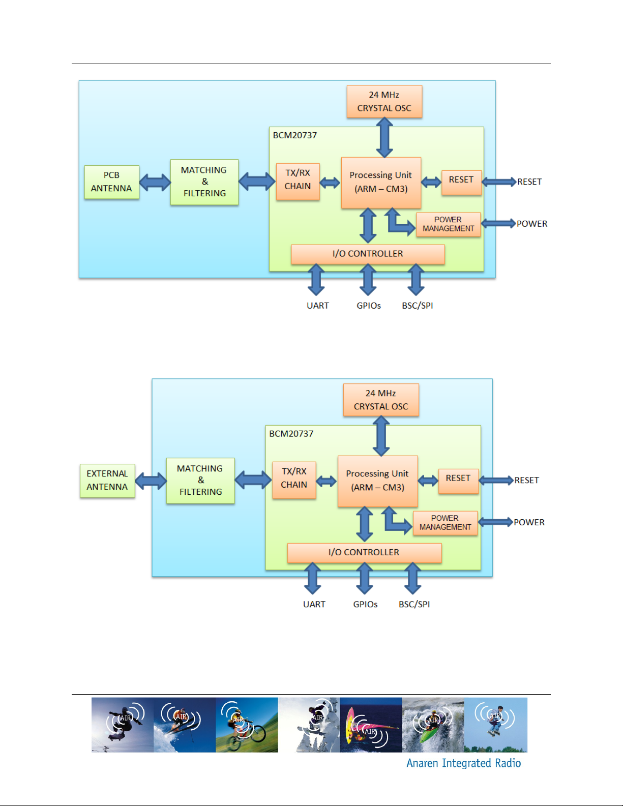
Figure 1 and Figure 2 show the functionality of A20737A and A20737C, respectively. Both
modules operate in a similar manner except the antenna part where A20737A communicates
through a built-in antenna, and A20737C communicates through an external antenna attached
to a U.FL antenna port.
Page 7
A20737x – User’s Manual Page 7 of 30
Release Date 09/25/14
Figure 1 The functionality of the A20737A, using an internal antenna
Figure 2 The functionality of the A20737C, using an external antenna
The description of the functional blocks shown in Figure 1 and Figure 2 is given as follows:
Page 8
Page 8 of 30 A20737x – User’s Manual
Item
Part Number
Manufacturer
Type
Gain (dBi)
1
Integral part of A20737A
Anaren
Integral Antenna
2
2
66089-2406
Anaren
Monopole whip, 6 mm lead
3
3
66089-2430
Anaren
Monopole whip, 30 mm lead
3
Release Date 09/25/14
Antenna
o The antenna couples energy between the air and the module. The integral
antenna and the external monopole antenna, both centered at 2441.75 MHz,
provide a near omni-directional antenna pattern with high efficiency such that the
application will work in any direction. Note that the end radiation pattern depends
not only on the antenna, but also the ground plane, enclosure and installation
environment.
Matching & Filtering
o The matching provides the correct loading of the transmit amplifier to achieve the
highest output power as well as the correct loading for the receive LNA to
achieve the best sensitivity.
o Filtering removes spurious signals to comply with regulatory intentional radiator
requirements, provides reduced susceptibility to power supply and digital noise,
and filters out RF and high frequency noise from the communication data and
control link.
TX/RX Chain
o TX/RX chain handles transmitting and receiving of the communication data
based on the radio register settings. It involves the coordination of several blocks
including modulator, demodulator, AGC control, frequency synthesizer and frame
control.
Crystal
o Crystal oscillator provides the necessary clock reference for the whole module
operation. The A20737A and A20737C modules use a 24 MHz crystal.
Power Management
o Power management ensures a stable supply for the internal functions, as well as
providing means for a low power sleep mode.
Table 1 Approved Antennas
1.5. Applications
Bluetooth SMART Systems
Industrial Control and Monitoring
Home/Building Automation
Lighting Systems
Low-Power Wireless Sensor Networks
Sports monitoring, health & wellness
Page 9

A20737x – User’s Manual Page 9 of 30
Release Date 09/25/14
2. Approvals and Usage
The A20737A and A20737C have been designed to meet many national regulations for
worldwide ISM band use. In particular, the radio modules have been certified to the following
standards.
2.1. Product Approvals
2.1.1. USA (Federal Communications Commission, FCC)
The A20737A and A20737C modules have been tested to comply with FCC CFR47 Part 15
sub-part C “Intentional Radiators” standard as well as Part 15 Sub-part B. The modules meet
the requirements for modular transmitter approval as detailed in FCC public notice DA 00-1407
released in June 26, 2000. The modular transmitter approval eliminates the need to re-perform
costly ‘intentional radiator’ testing when submitting an end product for certification.
(15.19a3) The module complies with part 15 of the FCC rules. Operation is subject to the
following two conditions: (1) this device may not cause harmful interference, and (2) this device
must accept any interference received, including interference that may cause undesired
operation.
Any changes or modifications not expressly approved by the party responsible for compliance
could void the user’s authority to operate the equipment.
2.1.1.1. FCC Labeling Requirements
The A20737A and A20737C modules have been labeled with their own FCC ID number and if
the FCC ID is not visible when the module is installed inside another device, then the outside of
the finished product into which the module is installed must also display a label referring to the
enclosed module. This exterior label can use wording such as the following:
Contains Transmitter Module FCC ID: X7J-A14070701
-or-
Contains FCC ID: X7J-A14070701
This device complies with Part 15 of the FCC Rules.
Operation is subject to the following two conditions:
(1) this device may not cause harmful interference, and (2) this device must accept any
interference received, including interference that may cause undesired operation.
Page 10
Page 10 of 30 A20737x – User’s Manual
Release Date 09/25/14
2.1.1.2. End User Manual
The end user manual should include the following statement:
This equipment has been tested and found to comply with the limits for a Class B digital device,
pursuant to part 15 of the FCC Rules. These limits are designed to provide reasonable
protection against harmful interference in a residential installation. This equipment generates,
uses and can radiate radio frequency energy and, if not installed and used in accordance with
the instructions, may cause harmful interference to radio communications. However, there is no
guarantee that interference will not occur in a particular installation. If this equipment does
cause harmful interference to radio or television reception, which can be determined by turning
the equipment off and on, the user is encouraged to try to correct the interference by one or
more of the following measures:
Reorient or relocate the receiving antenna.
Increase the separation between the equipment and receiver.
Connect the equipment into an outlet on a circuit different from that to which the receiver
is connected.
Consult the dealer or an experienced radio/TV technician for help.
2.1.1.3. RF Exposure
All transmitters regulated by FCC must comply with RF exposure requirements. OET Bulletin 65
“Evaluating Compliance with FCC Guidelines for Human Exposure to Radio Frequency
Electromagnetic Fields” provides assistance in determining whether proposed or existing
transmitting facilities, operations or devices comply with limits for human exposure to Radio
Frequency (RF) fields adopted by the Federal Communications Commission (FCC). The bulletin
offers guidelines and suggestions for evaluating compliance.
If appropriate, compliance with exposure guidelines for mobile and unlicensed devices can be
accomplished by the use of warning labels and by providing users with information concerning
minimum separation distances from transmitting structures and proper installation of antennas.
The following statement must be included as a CAUTION statement in manuals and OEM
products to alert users of FCC RF Exposure compliance:
To satisfy FCC requirements the antenna used with this transmitter must not be co-located or
operating in conjunction with any other antenna or transmitter except as permitted by FCC multitransmitter procedures.
2.1.2. Canada (Industry Canada, IC)
The A20737A and A20737C modules have been certified for use in Canada under Industry
Canada (IC) Radio Standards Specification (RSS) RSS-210 and RSS-Gen.
Page 11

A20737x – User’s Manual Page 11 of 30
Release Date 09/25/14
From section 3.2 RSS-Gen, Issue 3, December 2010, Modular Approval for Category I
Equipment or Category II Equipment:
“Modular approval permits the installation of the same module in a host device or multiple host
devices without the need to recertify the device. Equipment certification for a modular device
may be sought for either Category I equipment or Category II equipment.
Transmitters designed as modules for the installation in a host device may obtain equipment
certification as a modular device provided that the applicable RSS is met and the following
conditions in this section are met.”
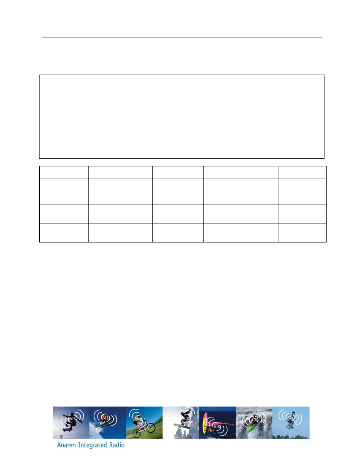
In section 7.1.2 Transmitter Antenna, it has been mentioned that the user manuals for
transmitters shall display the following notice in a conspicuous location:
Notice: Under Industry Canada regulations, this radio transmitter may only operate using an
antenna of a type and maximum (or lesser) gain approved for the transmitter by Industry
Canada. To reduce potential radio interference to other users, the antenna type and its gain
should be so chosen that the equivalent isotropically radiated power (e.i.r.p.) is not more than
that necessary for successful communication.
Avis: Sous la réglementation d'Industrie Canada, ce transmetteur radio ne peut fonctionner
qu’en utilisant seulement une antenne d'un type et d’un maximum (ou moins) de gain approuvé
pour l'émetteur par Industrie Canada. Pour réduire des potentielles interférences radio pour les
autres utilisateurs, le type d'antenne et son gain doivent être choisis de sorte que la puissance
isotrope rayonnée équivalente (PIRE) ne dépasse pas ce qui est nécessaire pour une
communication réussie.
Page 12
Page 12 of 30 A20737x – User’s Manual
Item
numéro d'article
Part Number
Référence
Manufacturer
Fabricant
Type
catégorie
Gain (dBi)
Gain
1
Integral part of
A20737A
Partie intégrante de
A20737A
Anaren
Integral Antenna
antenne intégrée
2
2
66089-2406
Anaren
Monopole whip, 6 mm lead
Antenne monopôle,
longueur 6 mm
3 3 66089-2430
Anaren
Monopole whip, 30 mm lead
Antenne monopôle,
longueur 30 mm
3
Release Date 09/25/14
In section 7.1.2 Transmitter Antenna, it has been mentioned that the user manuals for
transmitters equipped with detachable antennas shall also contain the following notice in a
conspicuous location:
Notice: This radio transmitter (IC: 8975A-A14070701) has been approved by Industry Canada
to operate with the antenna types listed below with the maximum permissible gain and required
antenna impedance for each antenna type indicated. Antenna types not included in this list,
having a gain greater than the maximum gain indicated for that type, are strictly prohibited for
use with this device.
Avis: Cet émetteur radio (IC: 8975A-A14070701) a été approuvé par Industrie Canada pour
fonctionner avec les types d'antennes énumérés ci-dessous avec le gain maximal admissible et
l’impédance d'antenne requise pour chaque type d'antenne indiqué. Les types d'antennes ne
figurant pas dans cette liste, ayant un gain supérieur au gain maximal indiqué pour ce type, sont
strictement interdits pour l'utilisation avec cet appareil.
2.1.2.1. IC Labeling Requirements
From section 3.2.1 RSS-Gen, Issue 3, December 2010, Labeling Requirements for the Host
Device:
The host device shall be properly labeled to identify the modules within the host device. The
Industry Canada certification label of a module shall be clearly visible at all times when installed
in the host device, otherwise the host device must be labeled to display the Industry Canada
certification number of the module, preceded by the words “Contains transmitter module”, or the
word “Contains”, or similar wording expressing the same meaning.
From section 5.2, RSS-Gen, Issue 3, December 2010, Equipment Certification Numbers and
Labels:
Every unit of Category I radio apparatus certified for marketing and use in Canada shall bear a
permanent label on which is indelibly displayed the model number and Industry Canada
certification number of the equipment model (transmitter, receiver, or inseparable combination
Page 13

A20737x – User’s Manual Page 13 of 30
Release Date 09/25/14
thereof). Each model shall be identified by a unique combination of a model number and a
certification number, which are assigned as described below in this section.
The label shall be securely affixed to a permanently attached part of the device, in a location
where it is visible or easily accessible to the user, and shall not be readily detachable. The label
shall be sufficiently durable to remain fully legible and intact on the device in all normal
conditions of use throughout the device’s expected lifetime. These requirements may be met
either by a separate label or nameplate permanently attached to the device or by permanently
imprinting or impressing the label directly onto the device.
The label text shall be legible without the aid of magnification, but is not required to be larger
than 8-point font size. If the device is too small to meet this condition, the label information may
be included in the user manual upon agreement with Industry Canada.
Section 5.2 continues:
The model number is assigned by the applicant and shall be unique to each model of radio
apparatus under that applicant’s responsibility. The model number shall be displayed on the
label preceded by the text: “Model:”, so it appears as follows:
Model: model number assigned by applicant
Label:
Contains/Contient IC: 8975A- A14070701
Notice: This device complies with Industry Canada licence-exempt RSS standard(s). Operation
is subject to the following two conditions: (1) this device may not cause interference, and (2) this
device must accept any interference, including interference that may cause undesired operation
of the device.
Avis: Cet appareil est conforme avec Industrie Canada RSS standard exempts de licence (s).
Son fonctionnement est soumis aux deux conditions suivantes: (1) cet appareil ne peut pas
provoquer d'interférences et (2) cet appareil doit accepter toute interférence, y compris les
interférences qui peuvent causer un mauvais fonctionnement du dispositif.
From section 7.1.4, RSS-Gen, Issue 3, December 2010, Radio Apparatus Containing Digital
Circuits (ICES-003):
“Radio apparatus containing digital circuitry which can function separately from the operation of
a transmitter or an associated transmitter, shall comply with ICES-003. In such cases, the
labeling requirements of the applicable RSS apply, rather than the labelling requirements in
ICES-003.”
For more information see: Industry Canada http://www.ic.gc.ca/
Page 14
Page 14 of 30 A20737x – User’s Manual
Release Date 09/25/14
2.1.2.2. RF Exposure
All transmitters regulated by IC must comply with RF exposure limits as set forth in RSS-102,
Issue 4, section 4, “Exposure Limits”. Furthermore RSS-102, Issue 4, Section 2 “Certification
Requirements”, provides assistance in determining the specific requirements for compliance. If
appropriate, compliance with exposure guidelines for mobile and unlicensed devices can be
accomplished by the use of warning labels and by providing users with information concerning
minimum separation distances from transmitting structures and proper installation of antennas.
The following statement must be included as a CAUTION statement in manuals and OEM
products to alert users of IC RF Exposure compliance:
Notice: To satisfy Industry Canada requirements the antenna used with this transmitter must
not be co-located or operating in conjunction with any other antenna or transmitter except as
permitted by Industry Canada’s multi-transmitter procedures
Avis: Pour satisfaire aux exigences d'Industrie Canada l'antenne utilisée avec cet émetteur ne
doit pas être colocalisée ni de fonctionner en conjonction avec une autre antenne ou un autre
émetteur, sauf dans la mesure permise par les procédures multi-émetteurs de l'Industrie
Canada
2.1.3. Europe (Conformité Européenne, )
The A20737A and A20737C modules have been certified for use in European countries covered
by ETSI regulations. The following tests have been performed and the module found to be
compliant to the requirements:
Test standard ETSI EN 300 328 V1.7.1 (2006-10)
Maximum Isotropic Radiated Power (Normal and Extreme Conditions)
Maximum e.i.r.p. Spectral Density
Frequency Range (Normal and Extreme Conditions)
Transmitter Spurious Emissions
Receiver Spurious Emissions
Electro-Static Discharge and RF Immunity (ETSI EN 301 489-17)
RF Exposure (ETSI EN 62311:2008)
Safety (IEC 60950-1:2005 and EN 60950-1:2006)
A helpful document that can be used as a starting point in understanding the use of short range
devices (SRD) in Europe is the European Radio Communications Committee (ERC)
Recommendation 70-03 E, downloadable from the European Radio Communications Office
(ERO) http://www.ero.dk.
Page 15
A20737x – User’s Manual Page 15 of 30
Release Date 09/25/14
The end user is responsible for ensuring compliance with harmonized frequencies and labeling
requirements for each country the end device is marketed and sold.
For more information see:
Radio And Telecommunications Terminal Equipment (R&TTE)
http://ec.europa.eu/enterprise/rtte/index_en.htm
European Conference of Postal and Telecommunications Administrations (CEPT)
http://www.cept.org/
European Telecommunications Standards Institute (ETSI) http://www.etsi.org/
European Radio Communications Office (ERO) http://www.ero.dk/
2.2. Potential Interference Sources
The radio modules operate in the unlicensed ISM band, in which there are many other
applications e.g. WLAN, Classic Bluetooth and microwave ovens. This can cause interference
that may, in certain conditions, prohibit radio communication. Frequency hopping nature of
Bluetooth SMART technology (which A20737A and A20737C modules use) makes it avoid
interference that may exist in the shared band, however, the link establishment may still be
affected by interference since only 3 channels are used during connection.
Some of the most common interferences are listed below:
2.2.1. WLAN
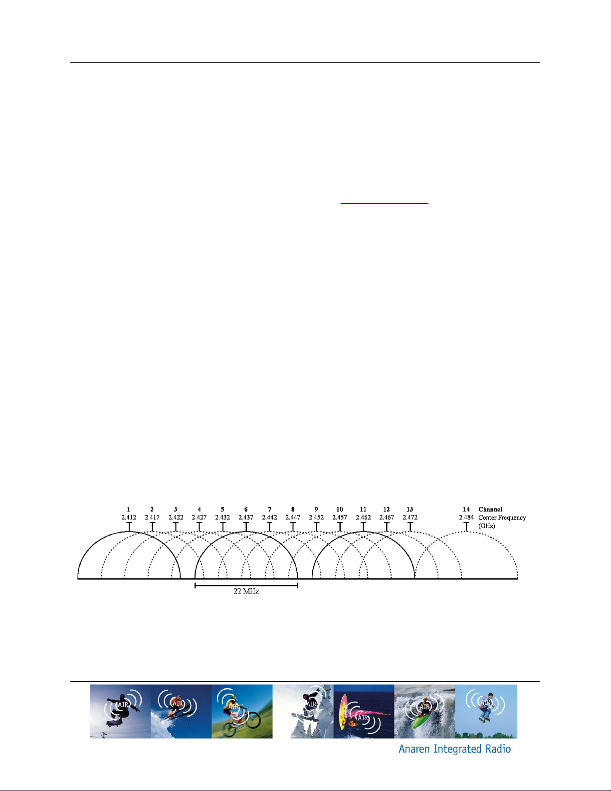
Wireless Local Area Networks (WLANs) are divided into a number of overlapping channels.
Figure 3 below shows the channels used by WLAN; for the US and Canada, only channels 1-13
may be used. Predominantly, channels 1, 6 and 11 are used to achieve non-overlapping
channels. The user is therefore encouraged to select a channel scheme that also has channels
falling in between, or entirely outside, WLAN channels. Using a detection scheme (clear channel
assessment) will enable the user to find channels with minimal interference from WLAN devices.
Figure 3 WLAN channels
2.2.2. Classic Bluetooth
Classic Bluetooth divides the 2.402-2.480 GHz band into 79 channels, each of which is 1MHz
wide. However, since Bluetooth changes channels rapidly (up to 1600 times a second), it is
Page 16

Page 16 of 30 A20737x – User’s Manual
Release Date 09/25/14
unlikely to cause continuous interference in a specific channel and can be overcome by
implementing a simple acknowledge/retransmit functionality.
2.2.3. Microwave ovens
A typical microwave oven uses a self-oscillating magnetron with a duty cycle below 50%,
because the tube is completely off for half of every AC mains cycle (8.33 ms in 60 Hz countries
and 10 ms in 50 Hz countries). The frequency of the microwave oven changes cyclically within
each AC mains synchronized on period, and is generally not predictable.
The user is encouraged to have packet transmission durations less than half the AC mains
period and implement an acknowledge/retransmit method.
2.2.4. Other Interference
Systems similar to the user’s system may also exist within range and may also be a source of
interference; some typical applications to consider are:
Alarm systems
o These typically use low duty cycles and are therefore easy to avoid using
acknowledge/retransmit methods
Car alarms (internal motion sensors)
Video surveillance
o These are typically operated on a fixed channel, determined at installation time
and can be avoided by using clear channel assessment. It may be useful to
change the channel used by the video surveillance equipment also, if possible.
2.3. Approved Usage
The A20737A and A20737C modules have been approved for use in the US, Canada and
Europe. The user is encouraged to use minimum power required to establish a link, thus
minimizing interference.
Changes or modifications to the module and/or operation outside the limits are prohibited and
could void the user’s authority to operate the modules.
2.3.1. USA and Canada
Within the USA and Canada, the A20737A and A20737C modules have been approved for use
as digitally modulated transmitters, for which they conform to the BW (a minimum of 500 kHz 6dB BW for US, a maximum BW of 0.5% of the carrier frequency for Canada), power spectral
density (max of 8 dBm / 3 kHz), total output power (max of 1W including the antenna gain) and
spurious radiation (harmonics and others including the restricted bands) requirements.
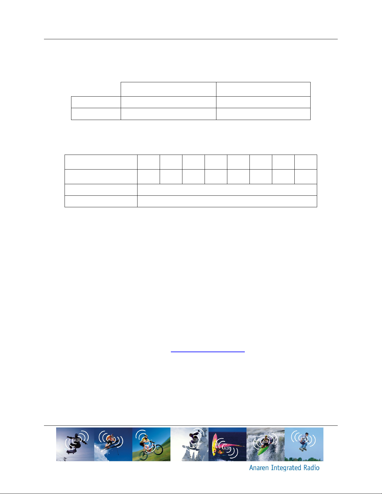
Table 2 shows approved frequencies of operations with the corresponding maximum output
power values. These modules must be operated at or below the indicated power levels. Using
the modules with higher power levels are prohibited, and will void the user’s authority to operate
the modules under current FCC/IC certification.
Page 17
A20737x – User’s Manual Page 17 of 30
Approved Frequencies (MHz)
Max Output Power (dBm)
A20737A
2402 - 2480
+3
A20737C
2402 - 2480
+3
Output Power(dBm)
+3
-1
-5
-9
-13
-17
-21
-25
TX Current (mA)
20
15
13
12
11
10
9.7
9.5
RX Current (mA)
25
Idle Current (mA)
3.5
Release Date 09/25/14
Table 3 shows available power levels from the device. Users are encouraged to use minimum
power required to establish a link, thus minimizing interference and current consumption.
Table 2 Approved Power Levels for FCC/IC and ETSI
Table 3 A20737x module available power levels and typical current consumptions
Please note that the specified current consumption numbers are for radio operation only and do
not include other MCU peripherals.
2.3.2. Europe
For Europe, the maximum allowed output power is 100mW with a spectral power density limit of
10mW/MHz. A20737A and A20737C modules comply with the power spectral density
requirements at their highest power level, therefore approved power levels given in Table 2
apply. Please refer Table 3 for the available power levels from this module.
2.3.3. Bluetooth
End products using A20737A or A20737C modules should have their own End Product Listing
(EPL) through Bluetooth SIG in order to be advertised as Bluetooth smart compliant. Please
check the easy-to-follow guide located at http://www.bluetooth.org for more information.
Page 18
Page 18 of 30 A20737x – User’s Manual
Parameter
Min
Max
Unit
Condition/Note
Supply Voltage (VDD_IN)
-0.3
3.8
V
Supply Voltage (VDD_RF)
-0.3
1.4
V
Voltage on any digital pin
-0.3
VDD_IN+0.3
V
RF input power
-10
dBm
Storage Temperature
-40
125
˚C
Solder reflow temperature
260
˚C
According to IPC/JEDEC J-STD-
020D
ESD
-4 4 kV
According to JEDEC STD 22,
method A114, Human body model
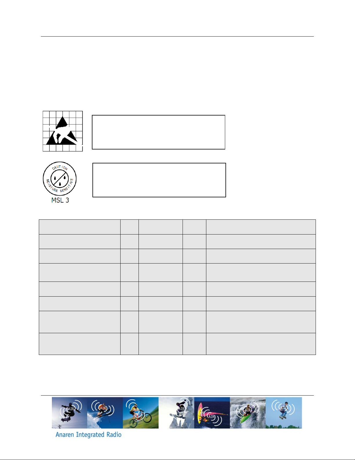
Caution!
ESD sensitive device. Precaution should be
used when handling the device in order to
prevent permanent damage.
Caution!
This assembly contains moisture sensitive
devices and requires proper handling per
IPC/JEDEC J-STD-033
Release Date 09/25/14
3. Electrical Characteristics
3.1. Absolute Maximum Ratings
Under no circumstances shall the absolute maximum ratings given in Table 4 be violated.
Stress exceeding one or more of the limiting values may cause permanent damage to the
device.
Table 4 Absolute Maximum Ratings
Page 19
A20737x – User’s Manual Page 19 of 30
Parameter
Min
Max
Unit
Condition/Note
Supply Voltage (VDD_IN)
1.7
3.6
V
Supply Voltage (VDD_RF)
1.14
1.26
V
Temperature Range
-30
+85
˚C
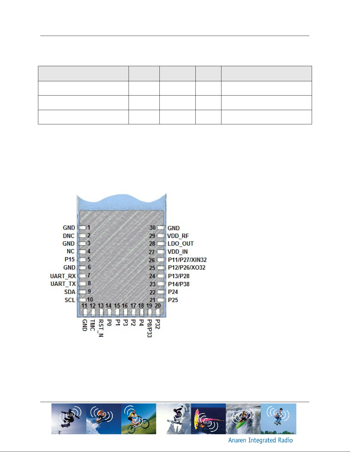
Figure 4 A20737x Module pin-out (viewed from top side)
Where applicable:
NC = “NO Connection”. Pin is
NOT connected internally.
DNC = “Do Not Connect”. Pin
reserved for internal use, ensure
mating footprint pads are
isolated.
GND = “Ground”. Connect the
maximum number possible
(minimum one for proper
operation).
Release Date 09/25/14
3.2. Operating Conditions
Table 5 Operating conditions
3.3. Pin Out
The A20737A and A20737C radios share a common pin-out and foot print, thus enabling the
use of the same application PCB layout for both. Below the pin-out is shown:
Page 20
Page 20 of 30 A20737x – User’s Manual
Pin
Number
Pin Name Pin Type Pin Description & Alternate Functions BCM20737 PIN
1, 3, 6, 11,
30
GND Com mon Ground Connect to GND
2 DNC
Do Not Connect. Connecting this pin to anything will significantly affect the
performanc e of the module and may void the end users' right, under FCC, to
operate the module
4 NC Pin is not internally connected
5 P15 Digital I/O
- Floating input after POR State
- GPIO: P15
- A/D Converter input
- IR_RX
- 60 Hz main
31
7 UART_RX Digital input, PD
- UART serial input - Serial data input for the HCI UART interface with a 10kΩ
internal pull down resistor. Leave unconnected if not used
- GPIO3
12
8 UART_TX Digital output, PU
- UART serial output - Serial data output for the HCI UART interface. Leave
unconnected if not used
- GPIO2
13
9 SDA I/O, PU
- Data signal for an external I2C devic e with a 10kΩ internal pull up resistor
- SPI_1: MOSI (master only)
- GPIO0
- CTS
15
10 SCL I/O, PU
- Clock signal for an external I2C device with a 10kΩ internal pull up resistor
- SPI_1: SPI_CLK (master only)
- GPIO1
- RTS
16
12 TMC Digital input, PD
Test mode control with a 10kΩ internal pull down resistor. Pull high for test
mode.
17
13 RST_N I/O, PU Active-low system reset with open-drain output & internal pull-up resistor 18
14 P0 Digital I/O
- Floating input after POR State
- GPIO: P0
- A/D Converter input
- Peripheral UART: puart_tx
- SPI_2: MOSI (master and slave)
- IR_RX
- 60 Hz main
- Not available during TMC=1
19
15 P1 Digital input, PU
Active-low write-control for the internal EEPROM with a 10kΩ internal pull up
resistor
20
16 P3 Digital I/O
- Floating input after POR State
- GPIO: P3
- Peripheral UART: puart_cts
- SPI_2: SPI_CLK (master and slave)
21
17 P2 Digital I/O
- Floating input after POR State
- GPIO: P2
- Peripheral UART: puart_cts
- SPI_2: SPI_CLK (master and slave)
22
18 P4 Digital I/O
- Floating input after POR State
- GPIO: P4
- Peripheral UART: puart_rx
- SPI_2: MOSI (master and slave)
- IR_TX
23
Release Date 09/25/14
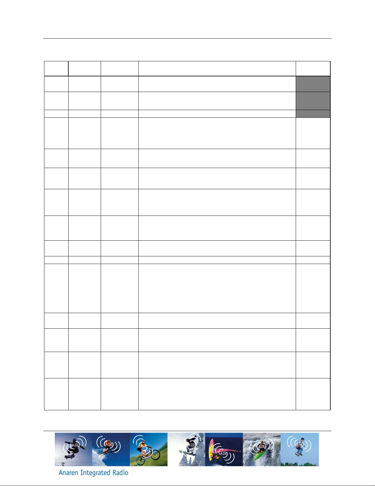
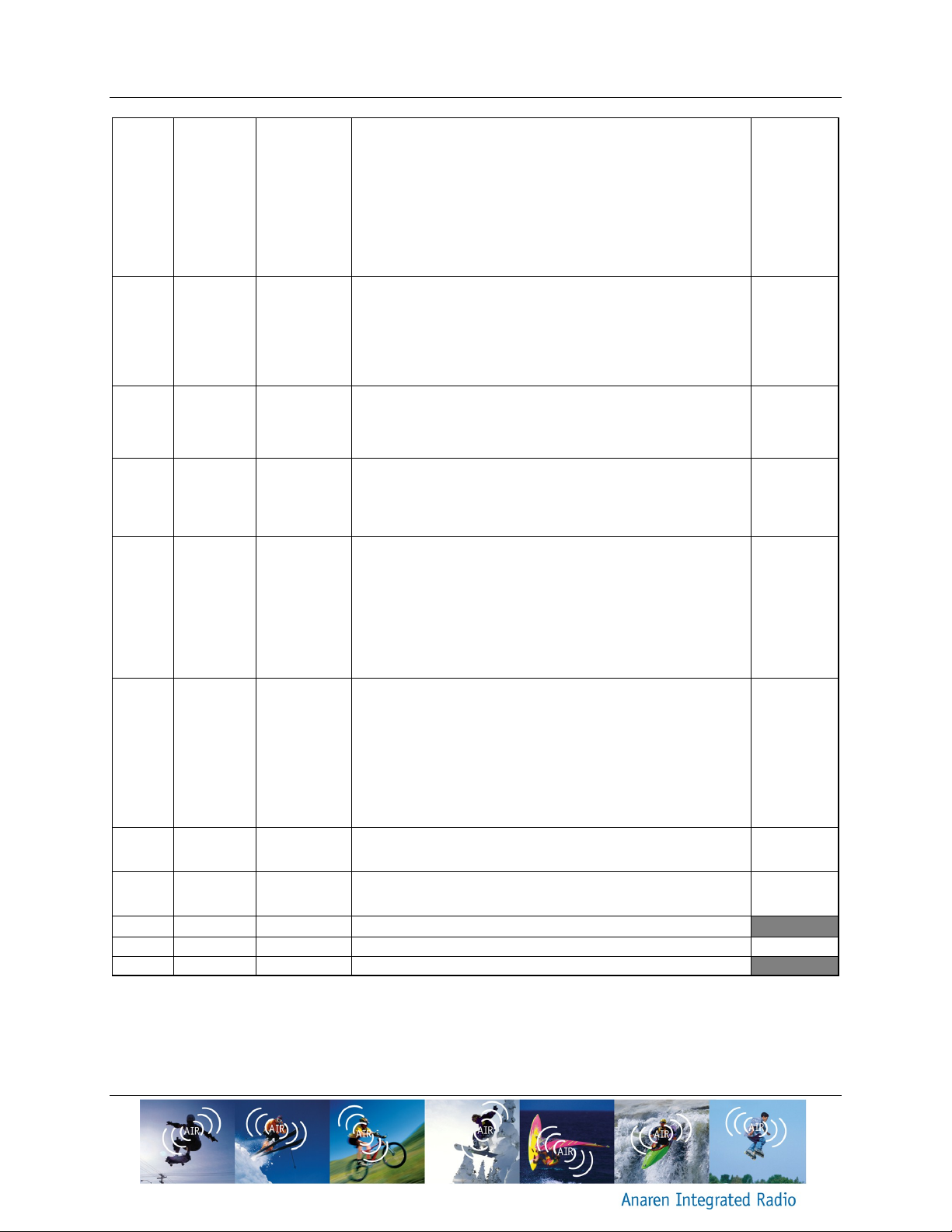
Table 6 A20737x pin descriptions with references to chip pins
Page 21
A20737x – User’s Manual Page 21 of 30
19 P8/P33 Digital I/O
- Floating input after POR State
- A/D converter input
- P8
+ GPIO: P8
+ External T/R switch control: ~tx_pd
- P33
+ GPIO: P33
+ SPI_2: MOSI (slave only)
+ Auxiliary clock output: ACLK1
+ Peripheral UART: puart_rx
24
20 P32 Digital I/O
- Floating input after POR State
- GPIO: P32
- A/D converter unit
- Peripheral UART: puart_tx
- SPI_2: SPI_CS (slave only)
- SPI_1: MISO (master only)
- Auxiliary clock output: ACLK0
25
21 P25 Digital I/O
- Floating input after POR State
- GPIO: P25
- Peripheral UART: puart_rx
- SPI_2: MISO (master and slave)
26
22 P24 Digital I/O
- Floating input after POR State
- GPIO: P24
- Peripheral UART: puart_tx
- SPI_2: SPI_CLK (master and slave)
- SPI_1: MISO (master only)
27
23 P14/P38 Digital I/O
- Floating input after POR State
- A/D converter input
- P14
+ GPIO: P14
+ PWM2
- P38
+ GPIO: P38
+ SPI_2: MOSI (master and slave)
+ IR_TX
30
24 P13/P28 Digital I/O
- Floating input after POR State
- A/D converter input
- P13
+ GPIO: P13
+ PWM3
- P28
+ GPIO: P28
+ LED1
+ IR_TX
+ PWM2
29
25 P12/P26/XO32 Digital I/O
- Low power oscillator output
- GPIO: P12
- GPIO: P26
32
26 P11/P27/XIN32 Digital I/O
- Low power oscillator input
- GPIO: P11
- GPIO: P27
1
27 VDD_IN Power (Analog) I/O pad and c ore supply (1.7 - 3.6V)
28 LDO_OUT Power (output) LDO Output (1.2V ) 3
29 VDD_RF Power (Analog) RF front-end supply (1.14 - 1.26V)
Release Date 09/25/14
Page 22
Page 22 of 30 A20737x – User’s Manual
Release Date 09/25/14
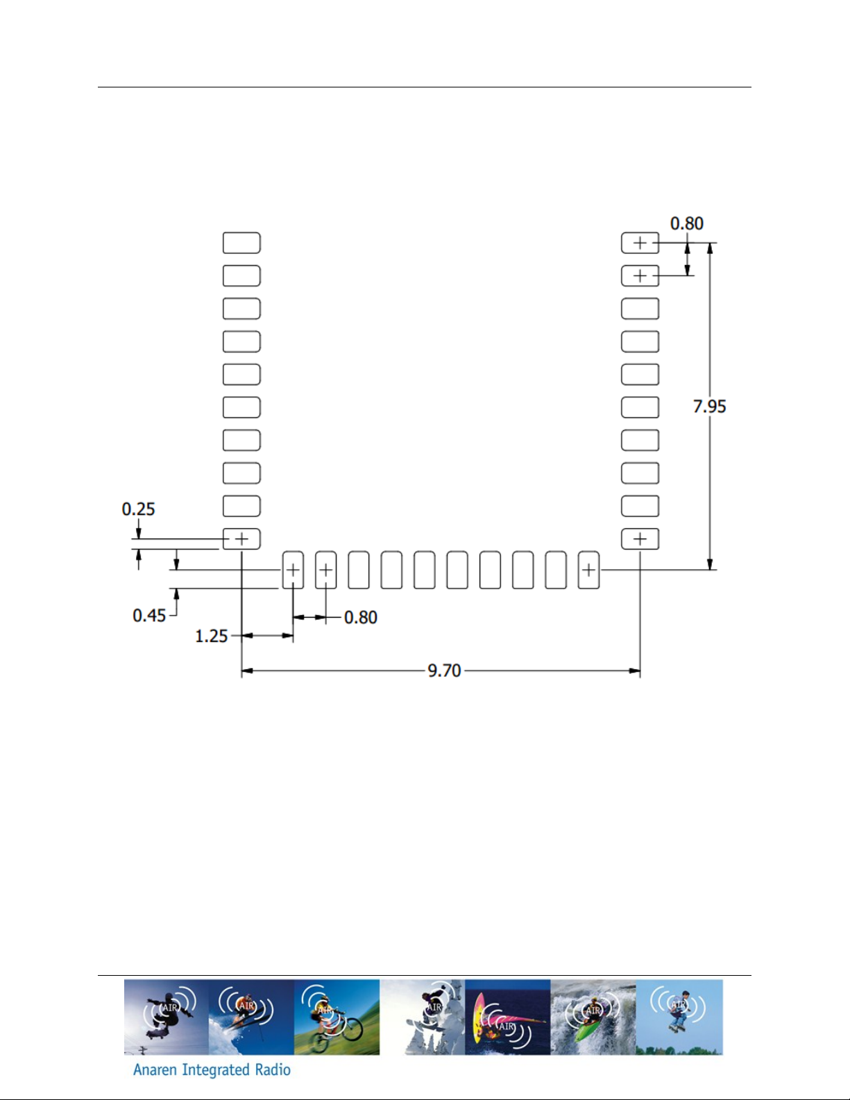
3.4. Recommended Layout (dimensions in mm)
Figure 5 Recommended PCB footprint.
Page 23
A20737x – User’s Manual Page 23 of 30
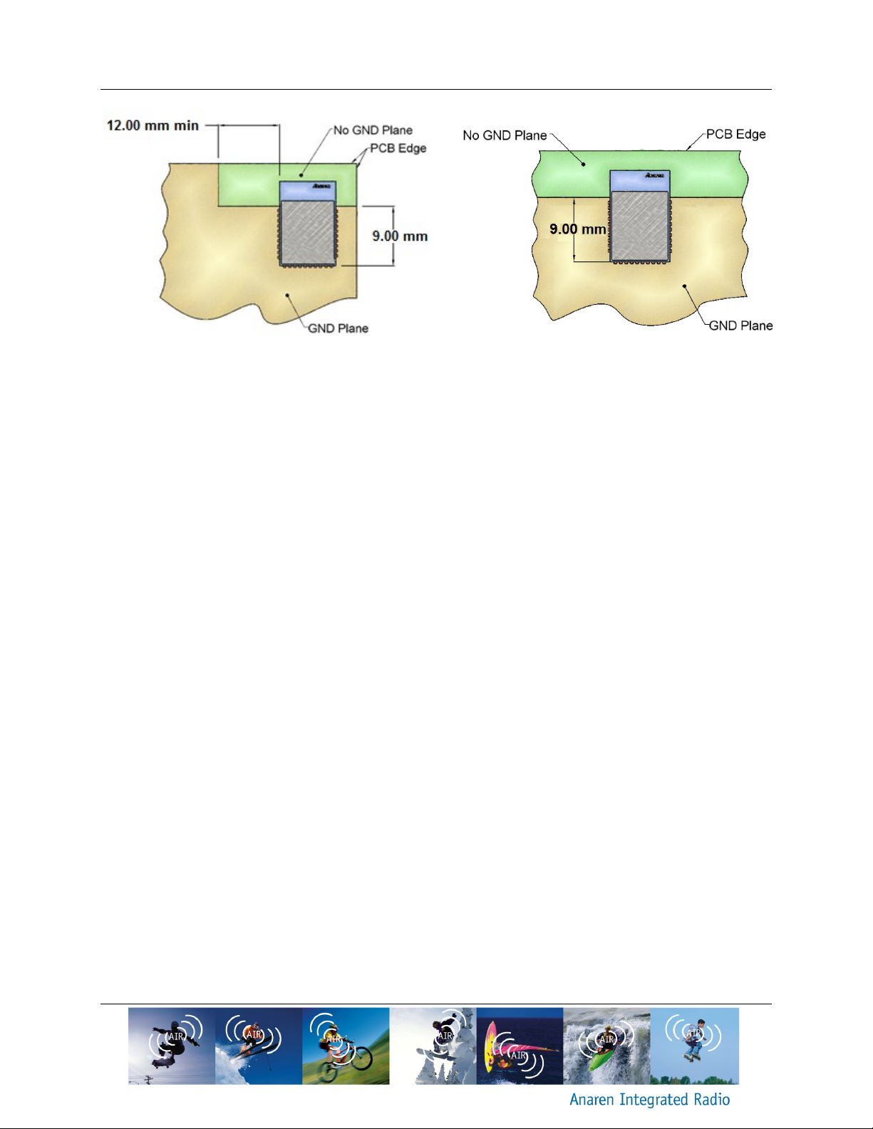
Figure 6 Mounting the module in a corner
Figure 7 Mounting the module along an edge
Release Date 09/25/14
“No GND” area is optional for A20737C modules. It may still be provided for compatibility with
the internal antenna version (A20737A).
3.5. Power Supply Considerations
Noise on the power supply line reduces the sensitivity of a receiver and can modulate onto a
transmitters signal, both of which causes a degradation of link quality and hence a reduction in
range.
The A20737A and A20737C modules have integral noise reduction from power supply to the
internal biasing pins, consisting of ferrite beads and decoupling capacitances. This arrangement
will take care of most supply voltage noise. For optimal performance in particular noisy
environments (switching regulators, motor controls, etc.) it may be necessary to add additional
noise reduction means, which can consist of a low noise LDO or additional LC filtering. Note
that if operated from a battery source there is no need for additional noise reduction.
The A20737A and A20737C modules have internal LDO which provides 1.2V voltage. The
output of this LDO is brought out to pin 28. Also, a separate input voltage pin (pin 29) is also
provided for convenience to the customers who wish to supply 1.2V to the RF circuitry
externally. In case this option is not desired, pin28 and pin29 should be tied together to power
the RF circuitry.
Page 24
Page 24 of 30 A20737x – User’s Manual
Release Date 09/25/14
4. Mechanical and Process
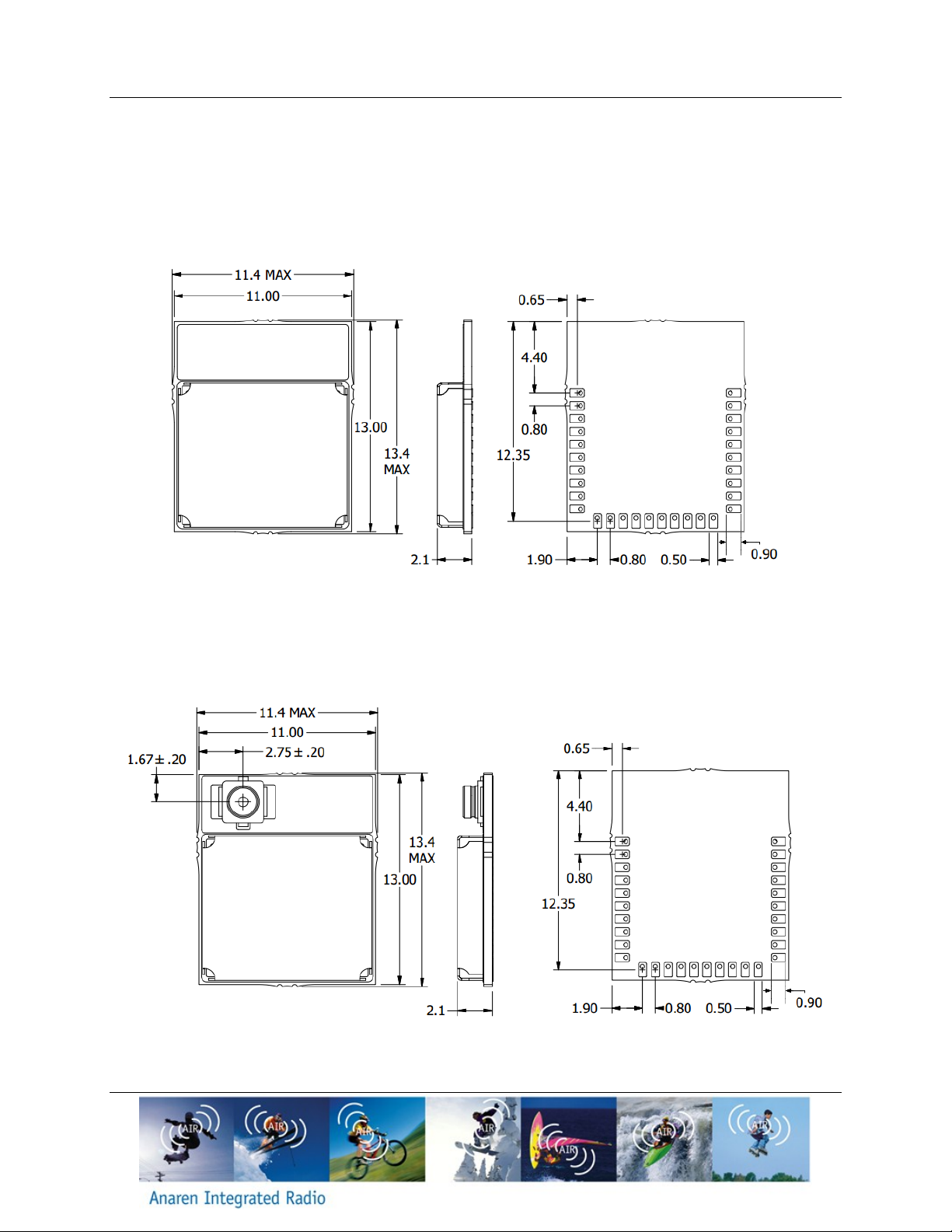
4.1. Radio Module Details (dimensions in mm)
4.1.1. A20737A
Figure 8 A20737A dimensions
4.1.2. A20737C
Figure 9 A20737C dimensions
Page 25
A20737x – User’s Manual Page 25 of 30
Release Date 09/25/14
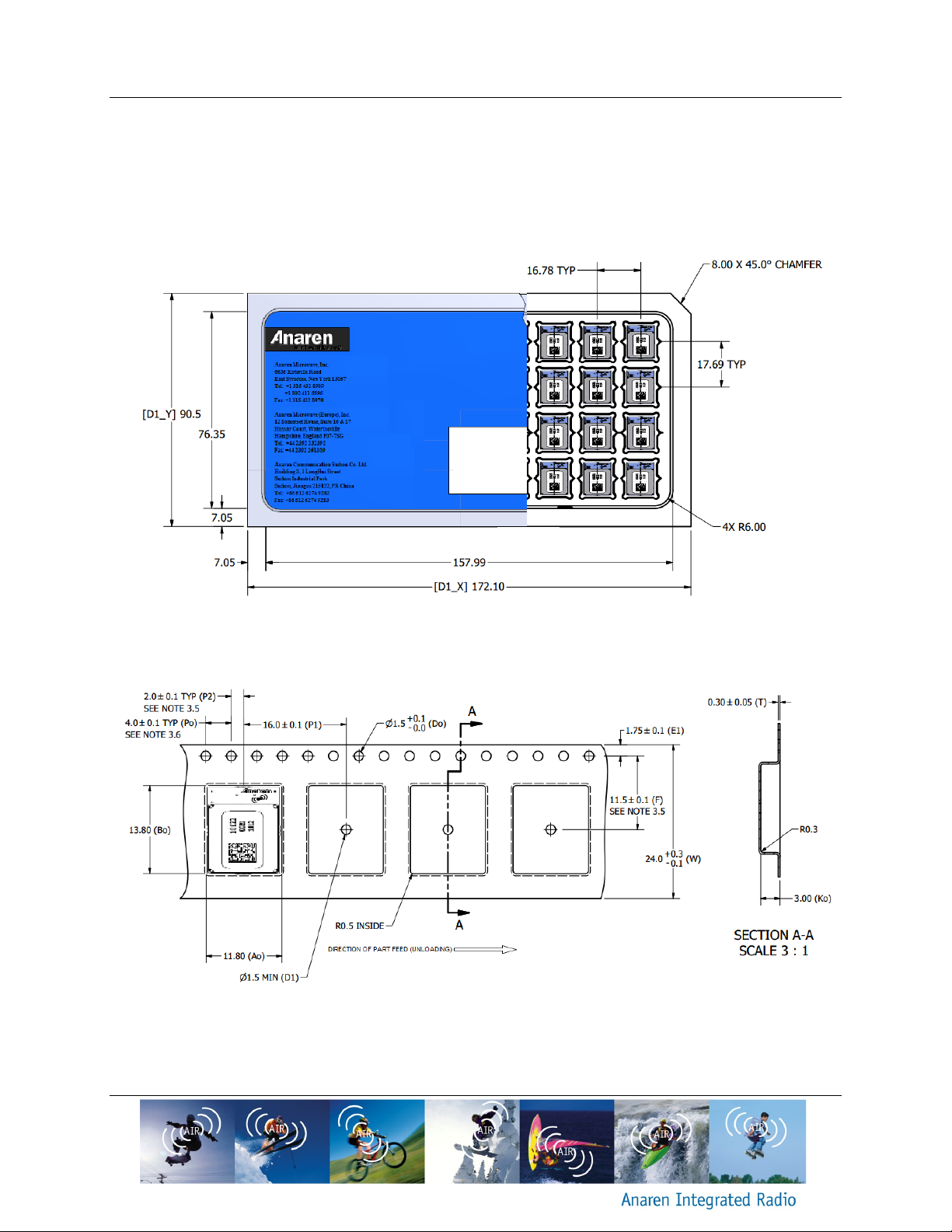
4.2. Packaging Details (dimensions in mm)
AIR modules are available in Matrix Tray and Tape & Reel packaging for high-volume
assembly. Details of packaging provided below:
4.2.1. Matrix Tray Packaging
Figure 10 A20737AxxGM and A20737CxxGM Matrix Tray Packaging Detail (36/Tray)
4.2.2. Tape-Reel Packaging
Figure 11 A20737AxxGR and A20737CxxGR Tape-Reel Packaging Detail (500/Reel)
Page 26

Page 26 of 30 A20737x – User’s Manual
Release Date 09/25/14
4.3. Soldering
AIR Modules may be mounted either manually (for prototyping or low volume production), or
automatically for high-volume production.
A no-clean tin/silver/copper (SAC) solder is recommended, however lead based no-clean
pastes may also be used.
CAUTION: AIR Modules are designed for no-clean fluxes only. DO NOT use waterbased fluxes that require aqueous cleaning after solder. Spot cleaning with a flux
remover and toothbrush may be performed with care.
4.3.1. Manual Mounting Procedure
The recommended soldering method is reflowing of a paste solder on a hot plate. This method
works provided the bottom of the board where the AIR module is to be mounted is accessible,
and there are no bottom-side components in the way.
An aluminum or copper block may be placed on the hot plate surface to transfer heat to a
localized area on the board where the AIR module is mounted
- Set the hot plate to the reflow temperature solder manufacturer’s recommended
- Apply solder paste to the pads on the board receiving the AIR module
- Place the AIR module carefully onto the dispensed solder
- Using tweezers or another holding device, carefully place board with AIR module onto
the hot plate surface (or metal block)
- Apply heat until reflow occurs, per solder paste manufacturer’s recommendations
- Carefully remove the board and place on a heat-resistant surface to cool
- Check assembly electrically to confirm there are no opens or shorts
Page 27
A20737x – User’s Manual Page 27 of 30
Release Date 09/25/14
4.3.2. Automated Mounting Procedure
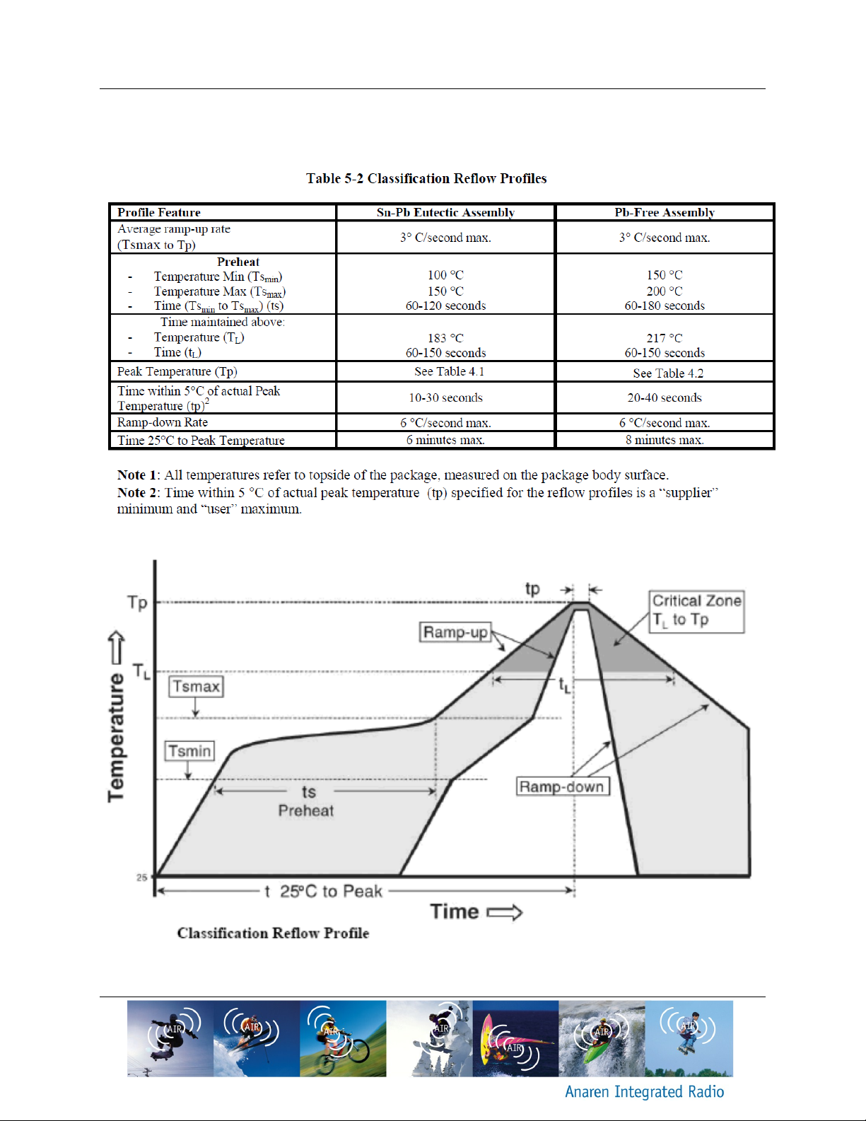
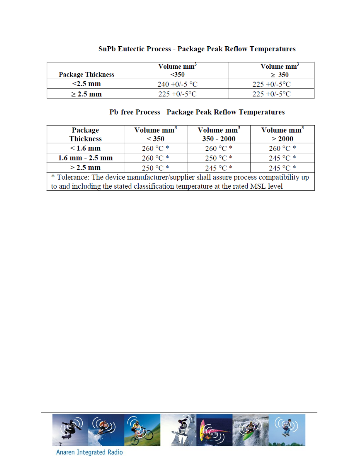
The AIR Radio Module recommended solder reflow profile is based on IPC/JEDEC J-STD-020.
Page 28
Page 28 of 30 A20737x – User’s Manual
Release Date 09/25/14
Page 29
A20737x – User’s Manual Page 29 of 30
Date
Author
Change Note No./Notes
09/25/14
Sula
Initial Draft
Release Date 09/25/14
DOCUMENT HISTORY
Page 30
Anaren Microwave, Inc.
6635 Kirkville Road
East Syracuse, NY 13057
Tel: +1 315 432 8909
+1 800 411 6596
Fax: +1 315 432 8970
Anaren Microwave (Europe), Inc.
12 Somerset House, Suite 16 & 17
Hussar Court, Waterlooville
Hampshire, England P07-7SG
Tel: +44 2392 232392
Fax: +44 2392 251369
Anaren Communication Suzhou Co. Ltd.
Bldg 3, No. 1 LongHui Street
Suzhou Industrial Park
Suzhou 215122, PR China
Tel: +86 512 6274 9282
Fax: +86 512 6274 9283
Attach distributor contact information
here
If you have additional questions, need samples, or would like a quote –
please email the AIR team at [email protected] .
For a full list of our franchised distributors, please visit our website:
http://www.anaren.com/air/
 Loading...