

Page 1
Power sensitive electronics
sure years of safe and
automotive or aeronautical environments and more.
Marine Electronics Displays
Mobile Offices (TV and Radio Vans)
Base Station Power
Industrial Controls
Temperature
DC/DC Converters
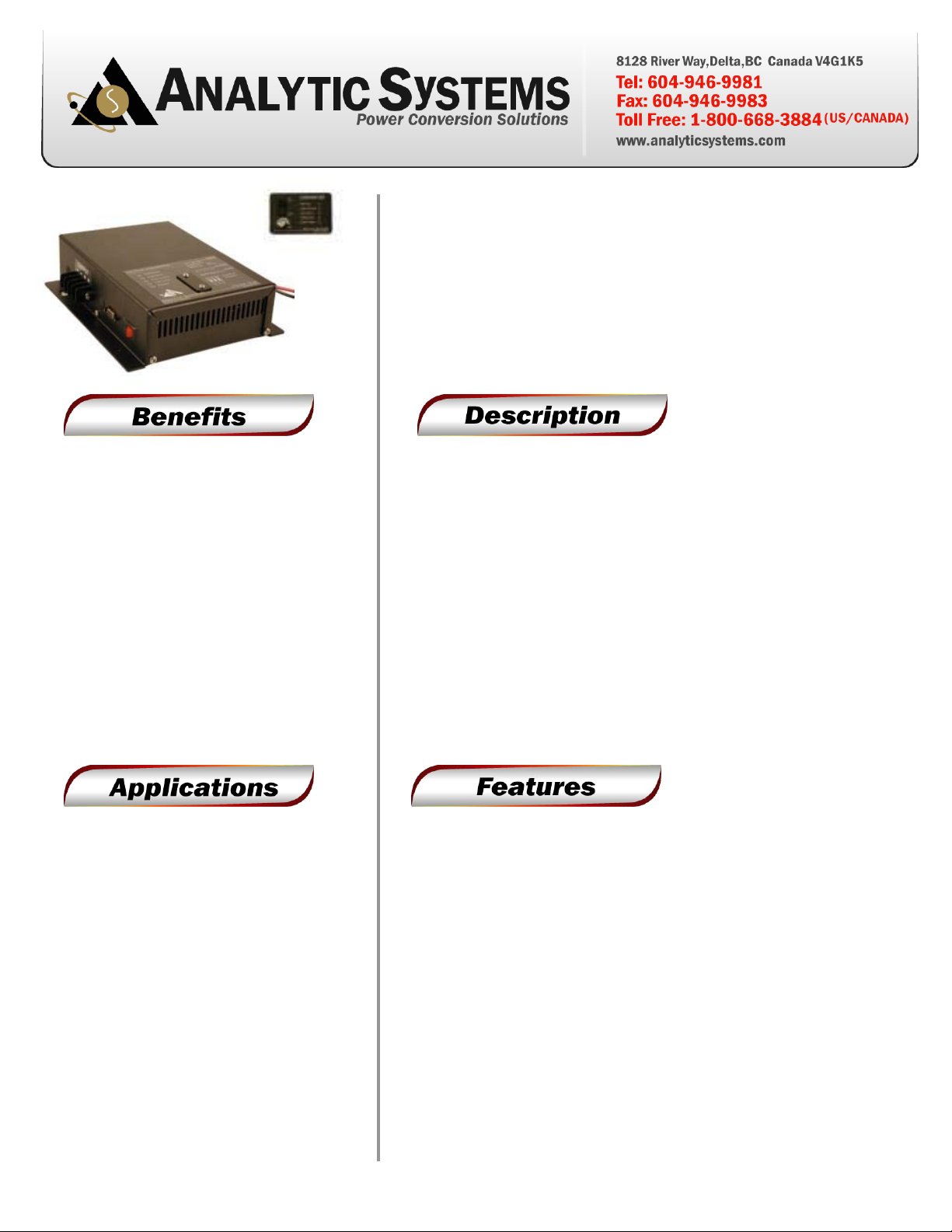
VTC305 Series S tep-Up Converter
• Ultra-Quiet
•
without interference
• Rugged & Reliable
• En
trouble free operation
•
•
• Automotive / RV
• Electric Utilities and Substations
•
(Radio & Telecommunications)
•
(OEM Applications)
• Field Work / Construction Sites
• Solar / Alternative Power Systems
• Any 12 or 24V Equipment
Step up a 12 VDC battery to between 13.5 and 17.0 or 24.0 and 27.5
VDC in 0.5 VDC increments (via 3 position DIP switch), or stabilize a 12
or 24 VDC power system.
Safety features include reverse input protection, low input voltage
alarm, low output voltage alarm, over temperature shutdown and alarm,
a dry contact alarm relay output and output overvoltage crowbar. If the
input voltage exceeds the regulated output voltage, the unit simply
passes the voltage through with full LC filtering and a single schottky
diode drop (0.5 VDC or less). Optional features include remote panel
monitoring with On/Off control.
Applications include temporar i ly brightening 12 volt headlights or work
lights, increasing voltage into an automotive or marine ignition system
for hotter spark and/or prevention of failures due to voltage drop during
engine start, stabilizing 12V and 24 VDC power systems in marine,
• Vibration proof output voltage
adjustment by 3 position DIP
switch
• Audible & visual indicators for
constant current, low input
voltage, low output voltage &
over-temperature
• Extremely rugged and well s uited
for marine and other demanding
environments
• High tolerance for shock and
vibration
• Ultra-quiet low EMI operation
• Current limiting protection
• Reverse input protection
• Output over-voltage
crowbar
• Dry contact output fail
relay
• Remote control option
• Wide-
operation available
• Parallel output di odes
available
• Conformal Coating and/or
Harsh Environment
Ruggedization Available
• 3 year parts and labour
warranty
Page 2
-25° to +40°C @ maximum output
(Optional -40°C extra wide temp. operation avail.)
0 - 95°C Relative Humidity
(non-condensing) with optional conformal coating
Audible Noise
NONE Ødb @ 3 ft
Typical Service Life
Input Volts (DC)
10.5-18 10.5-28
Input Amps (max)
30
Input Fuse (AGC)
20 x 2 Amp
Noise on Input
< 25 mV
Low Input
Voltage Alarm
Current Limit
30 Amps in
Output Nominal (op)
12 24
Input - 1V or 13.5 to 17.0 Input - 1V or 24.0 to 27.5
Whichever is greater Whichever is greater
Output Amps
♦ 27
Output Crowbar
Output Ripple & Noise
< 25 mV
Low Output
Voltage Alarm
Programmed Output
Voltage minus 2.5 VDC
Transient Response
< 1V for 50% Surge
Regulation (Line & Load)
Duty Cycle
Continuous 100% for 24 hrs per day
Efficiency
> 90% @ Maximum Output
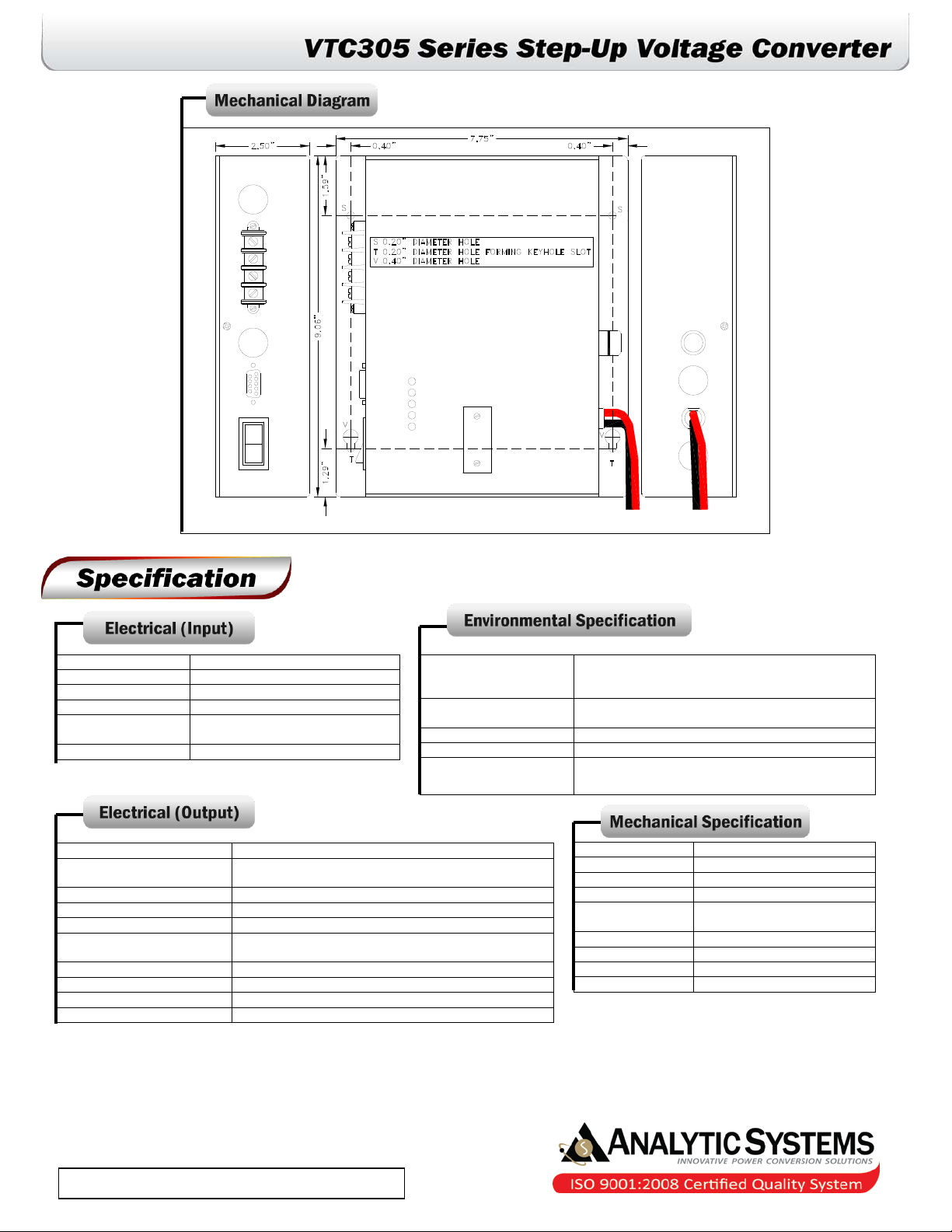
Length
Width
7.8 in / 19.8 cm
Height
2.5 in / 6.4 cm
Material
Black Anodize / Powder
Fastenings
All 18-8 Stainless Steel
Weight
4.0 lb / 1.8 kg
Connections
Warranty
3 years
Available From:
Operating Temp.
Range
Humidity
10.5 VDC
Isolation
Output Volts (DC)
Programmed Output Volts x 1.2
< +/- 0.5%
♦ The actual output current capability depends upon the input/output voltage ratio. To obtain
the actual output current capability at any given input voltage, use the following formula:
Output Amps = Input Volts/Output Vo lts x 27
For example, at 11 VDC in and 13.6 VDC out, the output current = 11/13.6 x 27 = 22.8 amps
Derate Linearly 2.5% per °C from 40°C
> 10 yrs. (87,600 hrs)
Any Input or Output to Case 500 VDC
Input to Output – Common Negative
9.1 in / 23.1 cm
Marine Grade Aluminium
Finish
Epoxy Coat
Four contact output terminals
 Loading...