

Page 1
Analytical Industries, Inc.
PI2- MS-500
PPB OXYGEN ANALYZER
OWNERS MANUAL
Revised Sep 20, 2016 Rev 2
Revised July 10, 2017 Rev 3
Revised Mar 05, 2018 Rev 4
Revised Sep 17, 2018 Rev 5
Page 2

Analytical Industries, Inc.
2
Table of Contents
Introduction
1
Quality Control Certification
2
Safety
3
Features & Specifications
4
Operation
5
Maintenance
6
Spare Parts
7
Troubleshooting
8
Warranty
9
(MSDS) Material Safety Data Sheet
1
0
Page 3

Analytical Industries, Inc.
3
1. Introduction
Your new PI2-MS 500/1000 PPB oxygen analyzer is a precision device designed to give you years of use for
analyzing single digit PPB (parts per billion) level oxygen concentrations. This micro-processor based analyzer
features the new breakthrough “Pico-Ion” Sensor Technology developed exclusively by Advanced Instruments
Inc. and an extensive sample system digitally controlled to offer the user the utmost in performance and
simplicity. The sample system consists of 316L stainless steel pneumatic valves with orbital welded or VCR type
connections.
The sample system features separate sample and span inlets, a pressure regulator and flow control orifice,
sample bypass loop for isolating the sensor and an integral oxygen scrubber (PI2-MS 500/1000 only) for
consistent zero gas, all of which are controlled by the user friendly micro-processor based electronics.
The digital electronics also feature auto or manual ranging, auto-zero and auto-calibration at user specified
intervals, data acquisition, temperature compensated output, user selected signal averaging and temperature
coefficient for fine tuning the sensor performance in varying temperature environments.
This analyzer is designed to measure the oxygen concentration in inert gases, gaseous hydrocarbons, hydrogen
and a variety of gas mixtures.
In order to derive maximum performance from your new oxygen analyzer, please read and follow the guidelines
provided in this Owner’s Manual.
The serial number of this analyzer may be found on the inside and at the back of the analyzer. You should note
the serial number in the space provided below and retain this Owner’s Manual as a permanent record of your
purchase, for future reference and for warranty considerations.
Serial Number: _______________________
Every effort has been made to select the most reliable, state of the art materials and components designed for
superior performance and minimal cost of ownership. This analyzer was tested thoroughly by the manufacturer
for best performance.
Advanced Instruments, Inc., appreciates your business and pledges to make every effort to maintain the highest
possible quality standards with respect to product design, manufacturing and service.
Page 4
Analytical Industries, Inc.
4
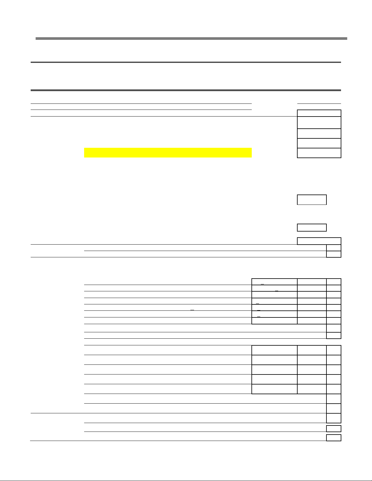
2. Quality Control Certificate
Quality Control & Calibration Certification
Customer:
Date:
Order No.:
Model No.:
PI2-MS-500 PPB Oxygen Analyzer
S/N:
Configuration
: A-1146-24-rG-500 PCB Assembly, Main/Display
Batch:
( )
A-1147-24-rG4 PCB Assy, Interconnect, 4-20mA, 0-1V, 1-5 V
Batch:
( )
A-1174 PCB Assy, Interconnect, ( ) 1-5 V + Contacts OR ( ) 4-20mA + Contacts
Ranges: 0-500ppb, 0-1000ppb, 0-10ppm, 0-100ppm, 0-1000ppm
Software Ver:
Wetted parts: 316SS sensor housing, flow resistor, pneumatic isolation valves, fittings, 1/8" dia tubing and 1/4"
compression type fittings for vent outlet and air. Pressure regulator (VCR type), Sample inlet (1/4" VCR); Sample,
Span and Bypass pneumatic valves (VCR type).
Note: Pneumatic valves require a constant air supply at minimum 80 psig
System Power: 110 VAC - 220 VAC
Temperature Controller set at 85 deg. F
Enclosure: Std. Bench 13.9x9.9x13.4"
( )
A-2829 Bezel, 19" Rack
Sensor:
( )
GPR-12-2000 MS-2E PPBOxygen Sensor
S/N:
Accessories:
Owner’s Manual
A-3491 Power Cord, Filtered (CABL-1008, FLTR-1014)
Expected
Observe
d
Value
Value
Pas
s
Test & Verify:
Default zero
0 +0.05 low range
Default span @ 25 µA
110 PPM+3 PPM
After sensor installation, reading on continued zero gas purge is < 1 PPM after
< 1 hour
hrs
Reading after calibration with _____ PPM oxygen span gas
+2% of _____ PPM
Baseline drift on zero gas over 24 hour period (+5% FS)
+5 PPB of reading
Noise level (+1% FS)
+1 PPB of reading
Reading after 24 hours in static (no flow to sensor) condition
< 20 PPM
Analog signal output 4-20 mA full scale
Analog Range ID output 1-5VDC full scale
Alarm 1
Alarm 2
SETPOINT - Set alarm thresholds
MODE - Verify activation mode HIGH / LOW relative to setpoint
ENABLED - Verify alarms do not activate and OFF replaces SETPOINT
DELAY - Verify setpoint must be exceeded before activation
SILENCE/BYPASS - Verify main menu option de-activates alarm
Overall inspection for physical defects
Options:
Correction Factors He, Ar and H2
Sample, Zero, Bypass and Standby enable from the rear of the analyzer
Other:
NA
Page 5
Analytical Industries, Inc.
5
3. Safety
This section summarizes the essential generic precautions applicable to all analyzers. Additional precautions
specific to individual analyzers are contained in the following sections of this manual. To operate the analyzer
safely and obtain maximum performance, follow the basic guidelines outlined in this Owner’s Manual.
Caution: This symbol is used throughout the Owner’s Manual to CAUTION and alert the user to
recommended safety and/or operating guidelines.
Danger: This symbol is used throughout the Owner’s Manual to identify sources of immediate
DANGER such as the presence of hazardous voltages.
Read Instructions: Before operating the analyzer read the instructions.
Retain Instructions: The safety precautions and operating instructions found in the Owner’s Manual should
be retained for future reference.
Heed Warnings: Follow all warnings on the analyzer, accessories (if any) and in this Owner’s Manual.
Follow Instructions: Observe all precautions and operating instructions. Failure to do so may result in
personal injury or damage to the analyzer.
Inlet Sample Pressure: Recommended 30-50 PSIG, 100 PSIG maximum.
Outlet Pressure: The sample gas must be vented atmospheric pressure.
Instrument Air Pressure: Operation of the pneumatic valves which require a dedicated source of
compressed air with a minimum of 80-100 psig: Note: Do not attempt to use the sample gas to operate the
pneumatic valves.
Oxygen Sensor: DO NOT open the sensor. The sensor contains a corrosive liquid electrolyte that could be
harmful if touched or ingested, refer to the Material Safety Data Sheet contained in the Owner’s Manual
appendix. Avoid contact with any liquid or crystal type powder in or around the sensor or sensor housing, as
either could be a form of electrolyte. Leaking sensors should be disposed of in accordance with local
regulations.
Mounting: The analyzer is approved for indoor use only. It may be used outdoors with optional enclosures.
Mount the analyzer as recommended by the manufacturer.
Power: Supply power to the analyzer only as rated by the specification in Section 4 and/or markings on the
analyzer enclosure. The wiring/cords that connect the analyzer to the power source should be installed in
accordance with recognized electrical standards and so they are not pinched, particularly near the power source
and the point where they attach to the analyzer. Never yank a power cord to remove it from an outlet or from
the analyzer.
ENSURE THAT POWER LINE INCULDES “SURGE PROTECTER” AND RFI/EMI FILTER TO PREVENT
INTERFERENCE FROM EXCESSIVE LINE VOLTAGE VARIATIONS
Operating Temperature: The maximum recommended operating temperature is 45 ºC. However, an
operating temperature of less than 35 oC is ideal to obtain maximum life of the oxygen sensor.
Heat: Situate and store the analyzer away from a direct source of heat.
Liquid and Object Entry: The analyzer should not be immersed in any liquid. Care should be taken so that
liquids are not spilled into and objects do not fall into the inside of the analyzer.
Handling: Do not use force when using the switches and knobs. Before moving your analyzer, be sure to
disconnect the wiring/power cord and any cables connected to the output terminals of the analyzer.
Serviceability: Except for replacing the oxygen sensor, there are no parts inside the analyzer for the operator
to service. Only trained personnel with authorization of their supervisor should conduct maintenance.
Troubleshooting: Consult the guidelines in Section 8 for advice on the common operating errors before
concluding that your analyzer is faulty. Do not attempt to service the analyzer beyond those means described
in this Owner’s Manual. Do not attempt to make repairs by yourself as this will void the warranty as per Section
Page 6

Analytical Industries, Inc.
6
9 and may result in electrical shock, injury or damage. All other servicing should be referred to qualified service
personnel.
Cleaning: The analyzer should be cleaned only as recommended by the manufacturer. Wipe off
dust and dirt from the outside of the unit with a soft damp cloth then dry immediately. Do not use
solvents or chemicals.
Oxygen Sensor: DO NOT open the sensor. The sensor contains a corrosive liquid electrolyte that could be
harmful if touched or ingested, refer to the Material Safety Data Sheet contained in the Owner’s Manual
appendix. Avoid contact with any liquid or crystal type powder in or around the sensor or sensor housing, as
either could be a form of electrolyte. Leaking sensors should be disposed of in accordance with local
regulations.
Nonuse Periods: Keep oxygen sensor from exposure to high oxygen levels as described in this manual (see
section Operation). Disconnect the power when the analyzer is left unused.
Warning: The analyzer must not be disconnected from power and gas line for more than a few hours to a
day. If it becomes necessary to disconnect power for extended period, remove sensor cable from
PCB A-1146 to disconnect sensor from electronic circuit. Failure to do so will keep sensor reacting with
oxygen that will continue to diffuse through sensor housing and may damage the sensor (with sample gas
flowing, oxygen diffusion through sensor housing becomes insignificant as it dilutes with sample gas).
It is recommended that the analyzer remain powered with gas flowing (if high purity sample gas is not
available, a gas with low PPM gas may be used with a flow rate as low as 0.1 SCFH). This will keep the sensor
ready for sampling a gas.
If it becomes necessary to transport the analyzer from one place to another, disconnect analyzer power only
when analyzer is to be transported and re-installed within a few hours to a day.
Caution: PI2-MS-M analyzer is equipped with MANUAL VALVE, turn sample inlet and sample outlet valves to
OFF position before removing sample gas connection. Failure to adhere to this instruction may result in
permanent damage to the sensor.
Page 7
Analytical Industries, Inc.
7
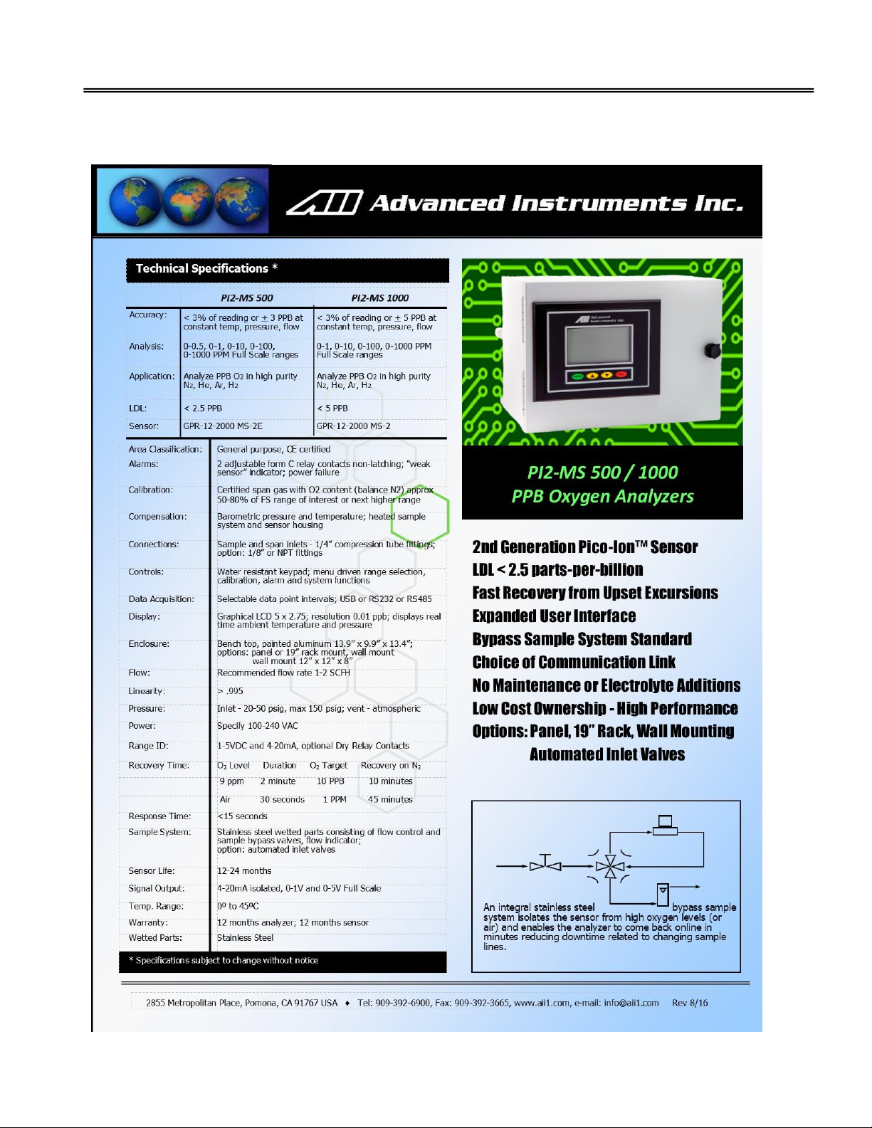
4. Specifications
Page 8
Analytical Industries, Inc.
8
5. Operation
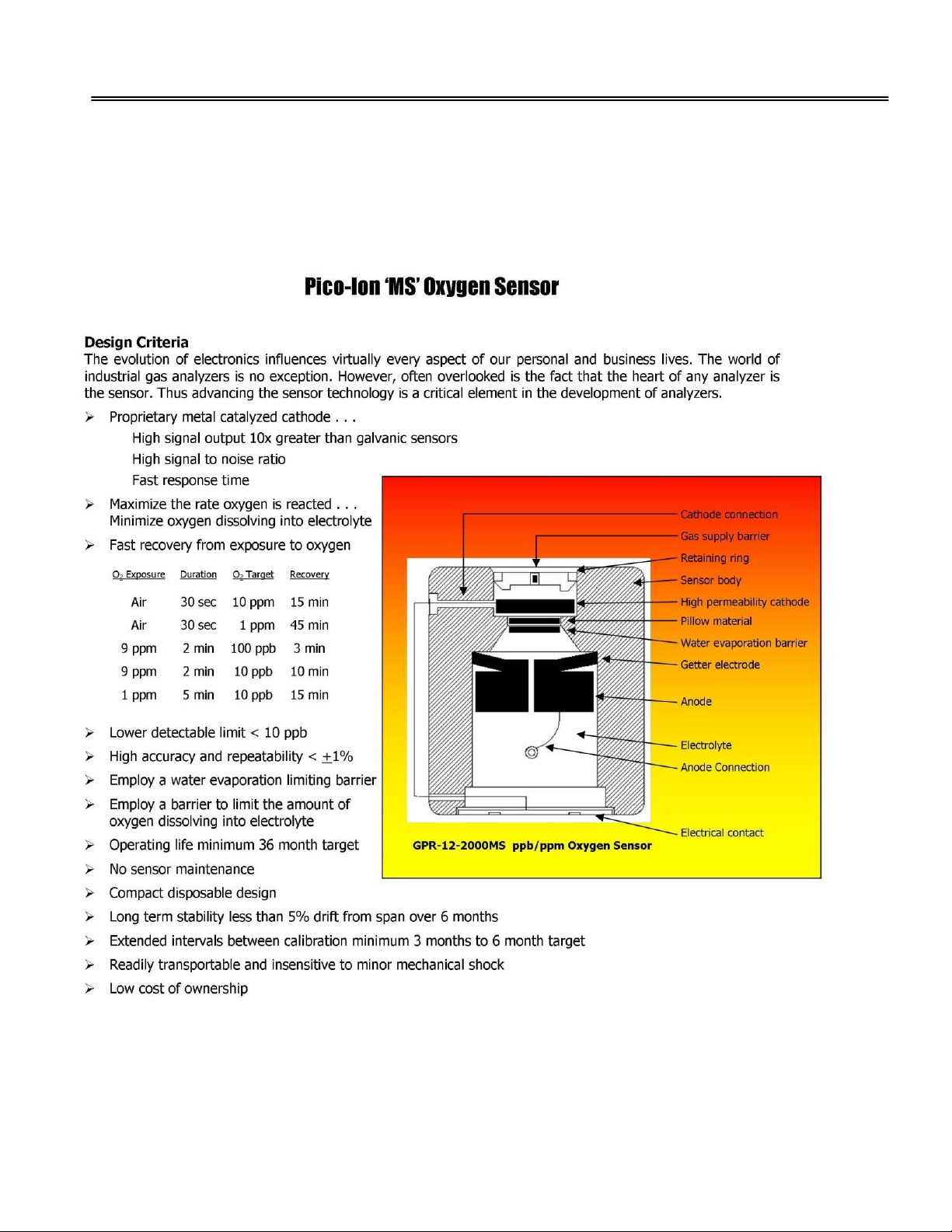
Principle of Operation
A breakthrough sensor technology of the second generation Pico-Ion oxygen sensor measures the partial
pressure of oxygen from less than 3 PPB to 1000 PPM level in inert gases, gaseous hydrocarbons, helium,
hydrogen and mixed gas streams.
Oxygen, the fuel for this electrochemical transducer, reacts chemically at the sensing electrode to produce an
electrical current output proportional to the oxygen concentration in the gas phase. The sensor’s signal output is
linear over all four ranges and remains virtually constant over its useful life. The sensor requires no maintenance
or electrolyte addition and is easily and safely replaced at the end of its useful life.
Page 9
Analytical Industries, Inc.
9
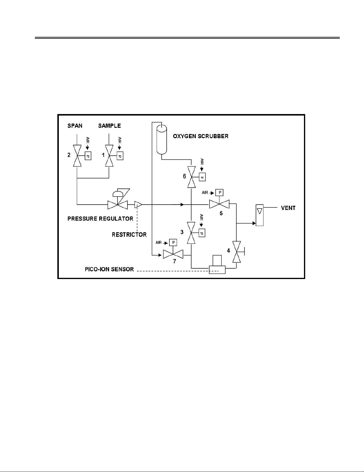
Sample System Flow Schematic
The PI2-MS 500/1000 analyzer is equipped with a micro-processor controlled sample system that features precise
flow control and pneumatic valves for introducing sample or span gases, isolating the sensor with an integral
bypass loop during standby and upset conditions and an oxygen scrubber for delivering consistent zero gas
(during zero calibration) to the sensor.
Note: The pneumatic valves require a minimum of 80 psig pressure to open. The maximum pressure allowed is
100 psig.
Valve Operation: OPEN CLOSED
Mode: BYPASS 1, 5 2, 3,4,6,7
ZERO 1,4,6,7 2,3,5
SPAN 2,3,4 1,5,6,7
SAMPLE 1,3,4 2,5,6,7
STANDBY NONE 1,2,3,4,5,6,7
Flow schematic of PI2-MS 500/1000
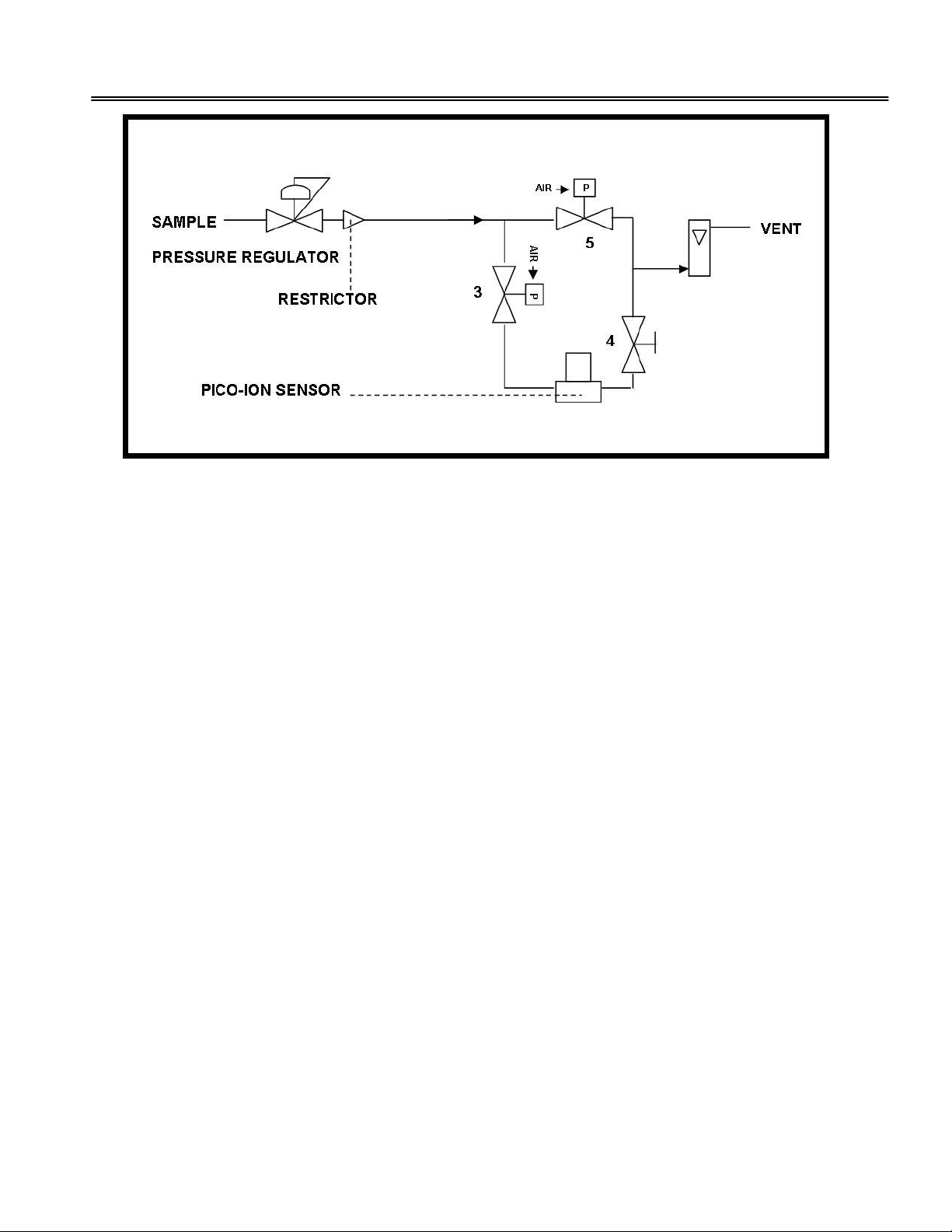
The PI2-MS 500/1000-B analyzer is equipped with a micro-processor controlled sample system that except that
these models do not have integral oxygen scrubber and separate Span gas inlet.
Note: The menus displayed by the PI2-MS-500/1000 B have been modified to reflect the absence of the span
inlet port and zero scrubber system.
Page 10
Analytical Industries, Inc.
10
Valve Operation: OPEN CLOSED
Mode: BYPASS 5 3,4
ZERO 3,4 5
SPAN 3,4 5
SAMPLE 3,4 5
STANDBY NONE 3,4,5
Flow Schematic of PI2-MS 500/1000-B
Caution: Do not change the valve positions until instructed to do so in this manual.
Page 11
Analytical Industries, Inc.
11
Other Sample Handling Considerations
The sample system may include optional components positioned upstream of the analyzer such as additional
pressure regulator, particulate filter, isolation/directional flow control valves etc. Check the QC sheet to confirm
the Sample System of your analyzer.
To avoid damaging the sensor or sample system, observe the following guidelines:
1. Do not draw a vacuum or over-pressure the sensor. When sample gas flows into the analyzer, any
restriction on the vent line will cause a pressure build up within the analyzer sample system, a sudden
release of the sample pressure will draw a vacuum on the sensor.
2. The vacuum generated in 1 above may cause the sensor to leak electrolyte (voiding the sensor
warranty). The electrolyte leakage may damage the electrical contacts of the upper section of the sensor
housing assembly, the electrolyte might enter in the sample system and if it does, it will require a
complete overhaul of the sample system.
3. Do not supply sample gas with pressure above the recommended limit. High positive pressure can
damage the integral pressure regulator, the sensor and or other sample system components.
4. Do not introduce calibration span gas from a pressurized cylinder without first regulating the pressure to
within the recommended limits (30-50 PSIG).
CAUTION: Do not vent the sample to a line with pressure above atmospheric pressure. If the vent line pressure
is above atmospheric (below 10-20 inches of water and is varying, use a back-pressure regulator set at 20 inches
of water to stabilize the pressure at the sensor.
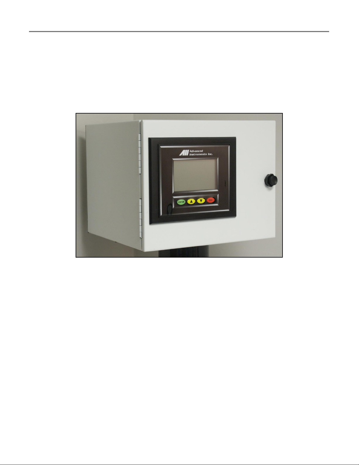
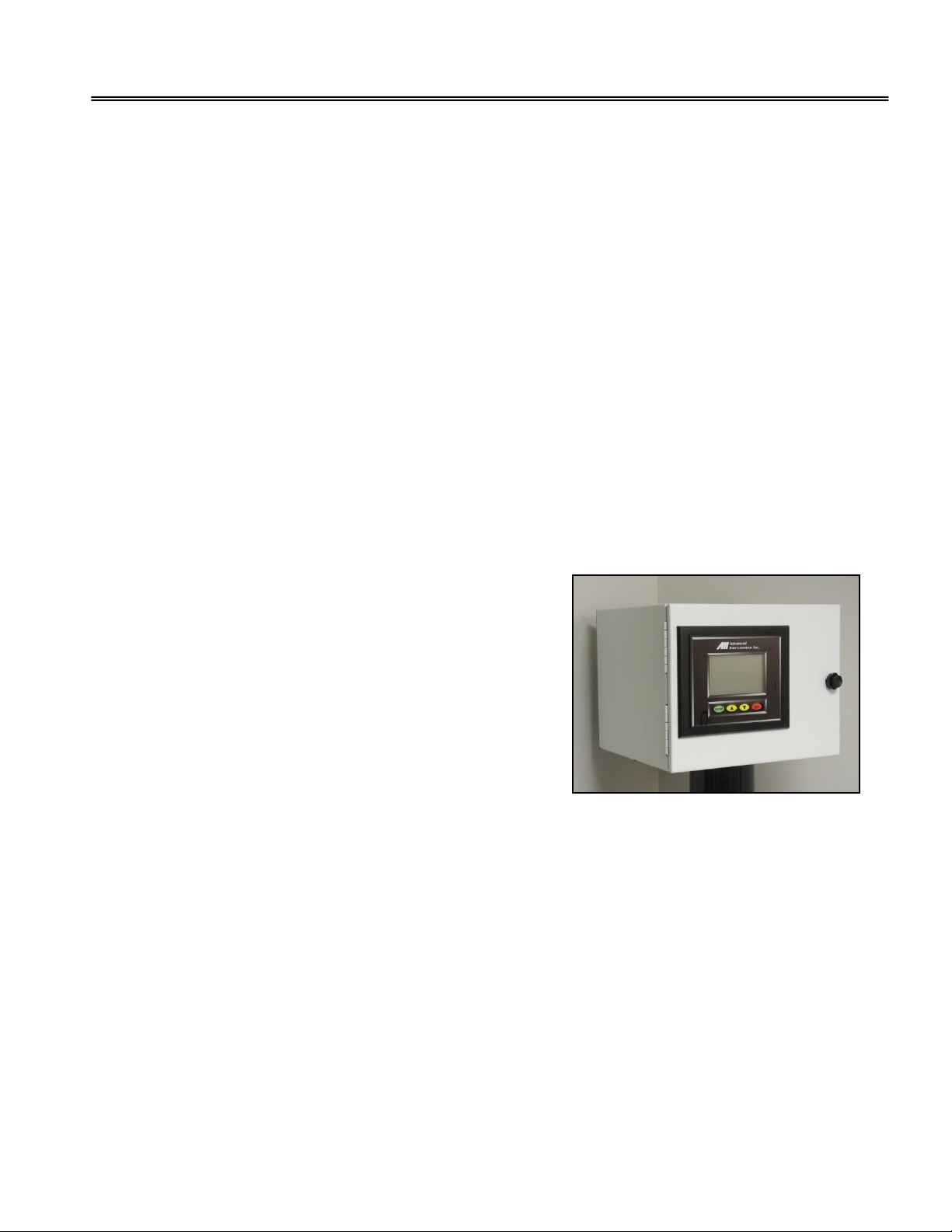
Installation
The PI2-MS 500/1000 series Oxygen Analyzers consist of an
electronic module, sensor housing and sample system housed in a
13.9”W x 9.9”H x 13.4”D enclosure suitable for bench-top or cart
applications. The enclosure can be panel or rack mounted with an
optional bezel. The analyzer includes a temperature controlled
heating system to maintain the temperature of the sensor at a preset temperature of 85 ◦F. The analyzer has been tested and
calibrated by the manufacturer prior to shipment.
Note: Analyzer is shipped from the factory with sensor placed in a
separate bag sealed under nitrogen. Install sensor as instructed later
in this section.
Caution: Do not change the factory settings of the analyzer until instructed to do so in this manual.
Sample/Span Gas Connections Considerations
Assemble the necessary hardware for mounting the analyzer and optional components (if provided or required by
the user). Perform the following steps
1. Use ¼” stainless steel compression type fittings for air input and sample vent line connections. Use ¼”
Face Seal type fittings for sample and span gas inlet connections. Caution: use clean/fresh gaskets for
making Face Seal type connections.
2. Use cleaned, preferably electro polished SS tubing for all sample/span gas connections. Plastic tubing
rated at 150 psig may be used to provide instrument air.
3. Review the application/sample analysis conditions to ensure the sample gas is suitable for analysis.
Sample and Span gas pressure 30-50 psig
Recommended sample and span gas pressure 30-50 PSIG (maximum pressure of 150 psig is acceptable). The 3050 psig pressure is recommended for ease of controlling of the gas flow rate by using the integral pressure
regulator.
Page 12

Analytical Industries, Inc.
12
Caution: The integral pressure regulator is rated at a maximum of 150 psig input pressure. Excessive pressure
may permanently damage the pressure regulator and may also introduce undue pressure on the oxygen sensor.
Instrument air pressure - 80 psig
Analyzer sampling system consists of seven pneumatically controlled diaphragm valves. The valves are actuated
by solenoid valves that deliver air to the pneumatic valves. Minimum pressure required to activate the pneumatic
valve is 80 psig. Set the instrument air at 80 PSIG. A maximum air pressure of 100 psig may be used. However,
do not use air pressure above 100 psig. Excessive pressure may damage the solenoid valves controlling the
pneumatic valves.
Caution: The pneumatic valves require a dedicated source of instrument air at a minimum of 80 psig. Do not
attempt to split the sample gas feed to operate the pneumatic valves.
Power Requirement
The analyzer is rated at 100-240 VAC. Before establishing power to the analyzer, check the rating printed at the
back of the analyzer to ensure that the power available meets the required ratings.
Caution: Incorrect power may result in safety hazard and damage to the analyzer.
Establish power to the analyzer by the power cable provided with the analyzer. Ensure that EMI/RFI filter is
attached as close as possible to the analyzer power input terminal.
ENSURE THAT POWER LINE INCULDES “SURGE PROTECTER” AND RFI/EMI FILTER TO PREVENT INTERFERENCE
FROM EXCESSIVE LINE VOLTAGE VARIATIONS
Signal Output
The analyzer provides 0-1 VDC, 0-5 VDC and 4-20 mA isolated full scale output. Keep signal output lines separate
from AC power lines. For optimum results when connecting signal output to an external recording device, e.g., a
printer or a PLC, do not bundle signal output wires with power cable (bundling signal output and AC power line
may introduce excessive noise on the signal output line). Keep wire lengths taking signal output to a recording
device to less than three meters.
Mounting the Analyzer
The PI2- MS 13.9”Wx9.9”Hx13.4”D configuration is designed for bench-top or cart use. The analyzer can be panel
15”Wx12”H or rack 19”Wx12”H mounted with the optional bezels. When mounting the analyzer in a 19” rack,
allow sufficient room to access terminal connections at the rear of the enclosure.
When equipped with the optional bezels, the PI2- MS bolts directly to any flat vertical surface, wall or bulkhead
plate with the appropriate cutout. To facilitate servicing the interior of the analyzer, position it approximately 5
feet off the floor.
Establishing Gas Connections
The PI2-MS is designed for positive pressured samples and requires connections for incoming sample, span
calibration gas, instrument air (for the solenoid valves controlling the pneumatic valves) and the sample/span gas
vent.
NOTE: PI2-MS-B does not have a separate Span inlet port. For these models, the user must connect the Span gas
to the Sample inlet port by using a TEE adaptor and a THREE-WAY valve for manually selecting the Sample or
Span gas.
Page 13

Analytical Industries, Inc.
13
Note: The preset of the integral pressure regulator and a restrictor in the sample line regulate the flow of the
incoming sample and span gas.
Procedure
1. Connect the instrument air supply to the tube fitting labeled AIR. Set air pressure at 80-100 psig.
2. Connect sample vent line to the tube fitting labeled SAMPLE VENT. Caution: Vent sample to
atmosphere. Use minimum ¼ inch tubing and keep the vent tube as short as possible (to minimize the
back pressure on the sensor)
3. Connect sample line to the face seal fitting connection labeled SAMPLE IN. Set sample input pressure
at 30-50 psig.
4. Connect span gas line to the face seal fitting connection labeled SPAN IN. Set the span pressure at
30-50 psig.
Caution: When making Face Seal sample and span gas connections, use fresh, clean and unscratched gaskets to
ensure leak free connections. To tighten connections, always use two ranches to prevent twisting of bulkhead
fittings.
Purging Sample and Span Gas Lines
It is recommended that before tightening the Face Seal connection, bleed the sample/span tubing up to the
sample/span port of the analyzer for 5-10 minutes to remove air trapped in the sample/span gas tubing.
Page 14

Analytical Industries, Inc.
14
Establishing Power to the Analyzer
Power to the analyzers is supplied by an integral universal 100-240VAC power supply. The appropriate AC line
voltage is supplied by using a standard power cord connected to the universal power entry module. Ensure that
EMI/RFI filter on the power cord remains intact and close to the power entry module.
ENSURE THAT POWER LINE INCULDES “SURGE PROTECTER” AND RFI/EMI FILTER TO PREVENT INTERFERENCE
FROM EXCESSIVE LINE VOLTAGE VARIATIONS
Check power rating of the analyzer printed at the back of the analyzer and make sure that a proper
AC voltage supply is available. Incorrect AC power may cause safety hazard and damage to the
analyzer.
Electrical Connections
ALL CONNECTIONS ARE MADE VIA TERMINAL BLOCKS AND ARE MARKED AS BELOW. TO MAKE ELECTRICAL
CONNECTIONS, PUSH THE LEVER WITH SMALL SCREW DRIVER, INSERT WIRE WHEN SLOT OPENS
RANGE ID –V
RANGE ID +V
4-20 + mA
4-20 – mA
0-5 -V
0-5+V
-V
+V
L-FLO B (optional)
L-FLO A (optional)
GND
+ 15 VDC
THRM 2
THRM 1
SEN –
SEN +
SYS FAIL B
SYS FAIL A
BNC Alarm contact normally closed
BC Alarm contact common
BNO Alarm contact normally open
ANC Alarm contact normally closed
AC Alarm contact common
ANO Alarm contact normally open
Page 15

Analytical Industries, Inc.
15
Alarm Relays and Signal Output Connections
As illustrated above the signal output (0-1 V, 0-5 V and 4-20 mA full scale), range ID voltage output, low and
high oxygen alarm relay contacts, low flow alarm contacts (optional feature), external sensor input (optional
feature) system fail alarm contact and +15 VDC auxiliary power (to actuate external solenoid valve option) are
hard wired (PCB mounted) terminal blocks located at the rear of the analyzer.
Remote Switch Functions (Optional)
The Remote Switch option allows the user to control the analyzer remotely through the back of the analyzer.
Remote switch function logic:
FUNCTION
INPUT A
INPUT B
INPUT C
SPAN CAL
OPEN
OPEN
SHORTED
ZERO CAL
OPEN
SHORTED
OPEN
BYPASS
OPEN
SHORTED
SHORTED
SAMPLE
SHORTED
OPEN
OPEN
STANDBY
SHORTED
OPEN
SHORTED
Shorted = Contact connected to +15V for 2 seconds
Inserting/Connecting Wires to Terminal Blocks
The terminal blocks have push-levers. When push-levers are pressed downward, the slots open to allow insertion
of wires in the slots. Use a small bladed screwdriver and press one lever of the terminal block down to open
contact slot. Insert the appropriate contact wire into the slot and release the lever to secure the wire in the
terminal block.
Caution: Use wires with proper ratings. Strip the insulation of the wires no more than 3/16”. Assure the stripped
wire ends of the cable are fully inserted into the terminal slots and do not touch each other or the back panel of
the analyzer enclosure.
Run signal and AC power lines separately to avoid EMI/RFI interference.
Danger: While connecting cables to relay terminals, ensure there is no voltage on cables to prevent electric
shock and possible damage to the analyzer.
To make a connection upon relay activation, connect live cable to the common terminal C and secondary cable to
the normally open NO terminal. To break a connection upon relay activation, connect live cable to the common C
and connect secondary cable to the normally closed NC terminal.
High and Low Oxygen Alarm Relays
The analyzer is equipped with two user adjustable alarms. When activated the alarms trigger SPDT Form C nonlatching relays @ 5A, 30VDC or 240VAC resistive. The alarms are fully adjustable by selecting the appropriate
ALARM menu option.
The alarm set point represents a value of oxygen. When the oxygen reading exceeds (high alarm) or falls below
(low alarm) the alarm set point, the relay is activated and the LCD displays the alarm condition.
Note: To prevent chattering of the relays, a 2% hysteresis is added to the alarm set point. This means that the
alarm will remain active until the oxygen reading has fallen 2% below the alarm set point (high alarm) or risen
2% above the alarm set point (low alarm) after the alarm was activated.
Note: The alarms may be deactivated by selecting the appropriate ALARM menu option (explained later in this
chapter). This feature is useful while replacing the oxygen sensor or during calibration when the oxygen reading
might well rise above the alarm set point and trigger a false alarm.
Page 16

Analytical Industries, Inc.
16
Power/System Failure Alarm
A dry contact rated at 30VDC @ 1A is provided as a power failure alarm. The contact is normally closed but opens
when the power to the analyzer is switched off or interrupted.
4-20 mA, 0-1 V and 0-5 V Full Scale Signal Output
The analyzer provides 0-1 V and 0-5 V full scale with negative ground and a 4-20mA full scale (isolated ground)
signals for external recording devices.
Caution: The integral 4-20mA voltage to current converter is internally powered and does not require external
power. DO NOT supply any voltage to either of the two terminals of the 4-20mA signal output. Failure to do so
will permanently damage the signal processing PCB.
Range Identification Voltage and 4-20 mA Output
A voltage output corresponding to each range is provided. The range ID voltage for first range is 5V and it
decreases by 1 V (to 4V, 3V and 2V) as the range shifts to the second, third and fourth range. An optional 4-20
mA range ID is also available. With 4-20 mA range ID, first range corresponds to 20 mA and dropping by 4 mA
with each range. Consult factory for this option.
Low Flow Alarm Option
An optional low flow alarm is available. The contact of the low flow alarm closes when gas flow falls below a
preset value, for example, below 1 SCFH. The alarm contact is rated at 30VDC @ 1A. Consult factory for this
option.
Two- way USB Communication Port
A real time bi-directional data lines is provided via USB port. This allows the access to the analyzer from a remote
computer to obtain status of the analyzer and/or initiate analyzer functions remotely.
Caution: In order to access the analyzer through a computer, you will require the proprietary optional software
(AII Configuration Software) from the factory. The software is available at a nominal charge.
By connecting a computer to the analyzer, all analyzer operational features can be accessed through the
computer, including the ability to store unlimited analyzer data on the computer hard disk.
RS-232 or RS-484 Communication Port
Optional RS-232 or RS-485 communication ports are available
Page 17

Analytical Industries, Inc.
17
Establishing Power to the Electronics
Once the power cord is inserted into to the power entry module at the rear of the enclosure, as illustrated above,
connect the plug end of the power cord to an appropriate AC outlet. When power is supplied to the analyzer, the
analyzer performs self-diagnostic checks and the 5” x 2.75” graphical back-lit LCD displays the following message
The analyzer will automatically go into the STANDBY mode
The main screen contains information pertinent to the analyzer. This information consist of
• Temperature and pressure at the upper left corner.
• The current MODE of the analyzer is indicated at the middle center of the LCD. A user customizable name
appears across the top center line of the LCD.
• Date and time at the upper right corner.
• Left hand side of the LCD shows if Alarm 1 & 2 are currently active (Example shows Alarm 1 active and
Alarm 2 inactive) and the speaker symbol is if the audible alarm is active or not.
• At the center of the LCD displays the current reading of the sensor and below that displays the range the
analyzer is currently in (0-500PPB manual range). AUTO will appear underneath the range ID when Auto
Ranging is selected.
Page 18

Analytical Industries, Inc.
18
• Right hand side of the LCD displays:
o BG: Background Gas selected.
o SC: Signal Conditioning option selected.
o A-Bypass: Auto Bypass enabled.
o A-Span: Auto Span Calibration enabled.
o A-Zero: Auto Zero Calibration enabled.
o Out Hold: Holds output until user has finished servicing analyzer.
o Def Rnge: Default Range enabled.
• Bottom right hand side of LCD displays if the analyzer is locked with a passcode.
What if Power to the Analyzer is interrupted?
In the event power to the analyzer is interrupted, all pneumatic valves will close. When power is restored, the
analyzer will return to operation in the STANDBY mode. The analyzer requires user intervention to bring analyzer
back to the same conditions that existed prior to power interruption.
Menu Navigation
Sample Screen:
• Press Menu/Esc to show Main Menu (if the menu is locked, a passcode prompt will appear)
• Press Enter to show graph screen
• Press Up to bypass an active alarm or accept a span or zero calibration in progress
• Press Down to abort a span or zero calibration in progress
• Hold Menu/Esc and Enter for ½ second to restart analyzer
• Hold Menu/Esc for ½ second to clear non-critical error messages
Main Menu:
• Press Up/Down to move selection pointer
• Press Enter to select a menu item
• Press Menu/Esc to return to previous menu
Graph Screen:
• Press Enter to cycle graph (O2, Temperature, Pressure)
• Press Menu/Esc to return to sample screen or Data Logging menu
• Press Up/Down to go to Next/Previous graph page (page number is displayed in upper-right corner,
page 1 is most recent data)
• Hold Up/Down for ½ second to zoom graph to next higher/lower range
Numeric/Alpha-numeric entry:
• Press or hold Up/Down to increase/decrease digit value
• Press Enter to edit next digit to the right or accept entry (right-most digit)
• Press Menu/Esc to edit the next digit to the left or abort entry (left-most digit)
There are several sub-menus within each main menu. The details of selecting certain features within a menu or
sub-menu are given below
Page 19

Analytical Industries, Inc.
19
Temperature Controlled Heater System
The PI2-MS-500/1000 series analyzers are equipped with a PID temperature control system. The controller is
programmed to maintain the temperature inside of the analyzer enclosure at 85F.
Caution: Do not change this setting. A higher temperature setting may drastically reduce sensor life and
possibly cause damage to the electronic circuitry of both the controller and the analyzer.
Warning: Keep the front door securely fastened/closed when the temperature controller is ON.
When power is applied to the temperature controller, the controller
tunes itself and control the temperature at the pre-set
temperature. It is recommended that when analyzer door is to
open (for example during trouble shooting), set the temperature
set point at 60F to turn the heater off to prevent overheating the
analyzer. When operating the analyzer under normal conditions,
set the temperature between 85F.
To changing the Temperature set point:
1. Press SEL to display the current set point
2. Press the UP/DOWN arrows until the desired value is displayed
3. Press SEL to accept the new set point value
Heater Runaway Protection
Part of the temperature controlled heater system is a runaway protection
circuit. The analyzer is protected in the event the temperature controller
should fail and thereby allowing the heater to runaway thus damaging the
interior of the analysis unit.
The runaway protection is provided by a J2 type device (a closed circuit
contact) positioned between the temperature controller and the heater.
This device cuts the power to the heater if the temperature inside the
analysis unit exceeds 70C (158 oF). Should the J2 device cut power to the
heater, correct the problem and replace the J2 device (the J2 device is a
single shot device and can’t be reset; once it is in an open circuit, it must
be replaced to restore power to heater)
J2 Heater runaway protection
Page 20

Analytical Industries, Inc.
20
Normal Operation of Analyzer
Sample Mode
Press Menu/Esc to advance to the main menu. Move cursor to select Valves: Standby and press Enter. Using
Up/Down, select Sample.
Auto Ranging Mode
In AUTO RANGING mode, output signal will shift to higher range when oxygen reading exceeds 99.9% of the
current range. Output will shift to the next lower range when oxygen reading drops to 85% of the next lower
range.
For example, if analyzer is reading 10 PPB on 0-100 PPB range and an upset occurs, output will shift to 0-1 PPM
range when oxygen reading exceeds 99.9 PPB. Conversely, once the upset condition is corrected, output will shift
back to 0-100 PPB range when oxygen reading drops to 0.085 PPM.
Note: In AUTO RANGING Mode, analog signal output (voltage and mA) will always correspond to the percent of
full scale range displayed. For example, at 50.0 PPB on 0-100 PPB range, analog signal will be 0.5 V and 12 mA.
Similarly, at 0.50 PPM on 0-1 PPM range, analog signal will be 0.5 V and 12 mA.
Manual Ranging Mode
In MANUAL RANGING, output will not shift automatically. Instead, when oxygen reading exceeds 125% of the
upper limit of the current range, output will freeze at 125% value of the selected range but analyzer display will
shift to the next higher range and show actual oxygen concentration.
To select MANUAL RANGING, select SAMPLE and press ENTER, then select MANUAL RANGING and then advance
cursor to the appropriate range and press ENTER again.
Note: In MANUAL RANGING, signal output will max out at about 125% of the selected range (even though
oxygen reading on the LCD will shift to the next higher range).
In MANUAL RANGING, following information will appear on the LCD display.
Page 21

Analytical Industries, Inc.
21
Installing the Oxygen Sensor
The analyzer is shipped with oxygen sensor separately bagged in a nitrogen filled metalized PE bag. Use the
procedure listed below to install the sensor or to replace an expired sensor. Sensor should be installed only after
the analyzer installation is complete and Sample and Span gas line have been connected and purged.
GPR-12-2000 MS-2/2E series sensors are for nitrogen, argon, hydrogen and helium application. For any other
gas mixture application, consult factory.
WARNING: The GPR-12-2000 MS-2/2E sensor can be used for any of the
above gas, however, if the sensor has been used with any one gas, allow
several sufficient time for the sensor to stabilize with new sample gas before
commencing analysis
CAUTION: Before removing the oxygen sensor from the sealed bag, perform
the following checks
1. Ensure all gas connections are secure and tight.
2. Select Sample valves from the main menu and ensure that the sample
pressure is set at 30-50 PSIG and air pressure is set at 80 PSIG.
3. Set the sample flow rate between 1-2 SCFH by adjusting the Pressure
Regulator setting. Ideal flow 1-2 SCFH.
4. Allow the analyzer sample system to purge for about 5 minutes (this
step is required only if the analyzer has been installed for the first
time).
5. From Main Menu, select Calibration, Enter sensor serial number
located on the box the sensor is shipped in.
6. Loosen the hex screw (or thumbwheel) at the bottom of the sensor
housing by using 5/16” ranch provided or by turning the thumb wheel. Remove the upper section of the
sensor housing by turning it 90 degree and then lifting it straight up.
7. Remove sensor from the sealed bag. Use a sharp pair of scissor to cut the bag. Do not use a spike to
poke the bag (this method may accidently damage sensor).
8. Place sensor with sensor's sensing surface facing down in the bottom section of the sensor housing
immediately (with gold color two ring PCB facing up). Remove the two red colored taps from the PCB of
the sensor. Place upper section of the sensor housing on top of sensor and gently lower it down until it
sits on the bottom section of the housing. Turn the upper section of the housing 90 degree and then
tighten the screw at the bottom of the sensor housing (after finger tight, turn the screw one full turn) or
tighten by turning the thumb wheel.
9. Confirm that sample flow rate is between 1-2 SCFH (adjust flow by turning the knob of the pressure
regulator as necessary). Ideal Sample flow is 1-2 SCFH.
Caution: Do not attempt to calibrate analyzer until it has reached a stable base line. This process may take up to
12-24 hours period. However, you may confirm that the newly installed sensor has the proper output by using a
span gas; with span gas flowing, analyzer will display an oxygen reading close to the span gas value plus the O2
reading before span gas was introduced. If the difference in the oxygen reading before and after introducing
span gas is not close to the span gas value (+/-30% of the span gas value with Factory Default Span setting, see
details later in this Section), you may consider replacing with another sensor.
Page 22

Analytical Industries, Inc.
22
What to Expect During the First 24 Hours
After analyzer installation has been completed, sample and span gas lines have been connected and purged,
install sensor as instructed in the section above. After sensor installation, analyzer should demonstrate a
downward trend for several hours. Generally, analyzer reading should drop below 100 PPM in less than 10-15
minutes and below 1 PPM in less than 1-2 hours. It is strongly recommended that the user record analyzer output
on a recording device, e.g., chart recorder or a PLC, to confirm downward trending of the analyzer.
Caution: This “clean-up time” or “recovery time” or “purge down time” depends on the user – the length of time
sensor has been exposed to ambient air before it was installed and how well sample gas line was purged before it
was connected to the analyzer sample input.
In the above graph, trending shown is very typical after a new sensor installation. Within 24 hours of installation
of new sensor, output dropped to less than 60 PPB and continued to trend down. This downward trend would
continue but the degree of trending down will decrease with time and eventually get to a stable reading.
NOTE: If after 2 hours of installation, oxygen value displayed is not below 1-2 PPM, perform a complete check of
all external sample system connections and allow a low ppm gas to flow overnight before concluding that sensor
is defective and notifying the factory.
Caution: Allow approximately 24 hours to stabilize the sensor before attempting initial Zero and/or Span
calibration of analyzer.
General guidelines for Analyzer Calibration
A typical downward trend of a newly installed
analyzer/sensor on N2 sample gas with oxygen
concentration near zero. Analyzer is in Auto Ranging mode
0-1 PPM
0-100 PPB
Page 23

Analytical Industries, Inc.
23
Zero Calibration
Theoretically, with zero gas, analyzer should display 0 PPB. However, even with pure gas (no oxygen), analyzer
will display a signal anywhere from 5-60 PPB. This oxygen value is called as the “Zero Offset” This offset is
contributed by
1. Minor leakage in the sample line connections.
2. Residual oxygen dissolved in sensor’s electrolyte
3. Tolerances in electronics components
In order to achieve accurate results in the low PPB levels, analyzer must be “Zero calibrated” before accurate
measurements could be made.
Zero Calibration Procedure
PI2-MS-500/1000 analyzer has an integral oxygen scrubber/purifier that removes oxygen from sample gas and
produces a zero gas for zero calibration; the scrubber can remove oxygen from a sample gas containing 1-2 PPM
oxygen down to less than 1 PPB.
The PI2-MS-B and PI2-MS-M do not have the integral Zero scrubber. To perform Zero calibration with PI2-MS-B
or PI2-MS-M, user must provide a true zero gas.
In order to perform a ZERO calibration,
• From the MAIN MENU screen, select Calibration.
• From CALIBRATION menu, select Zero Calibrate.
• The valves will actuate to Zero Bypass for 30 seconds to ensure the line is purged down before
continuing to Zero Calibration.
• On the bottom left of the LCD Zero Cal will appear with Up = Accept, Down = Abort. A timer of 15
minutes will appear underneath the valve mode selected. After the 15-minute timer is up then the
analyzer will attempt to perform the zero calibration. The user may Accept or Abort the calibration at any
time. Ensure reading is stable before prematurely Accepting the zero calibration.
After ZERO calibration, analyzer will automatically return to the previous valve mode selected.
CAUTION: If zero calibration is performed pre-maturely (analyzer still trending down), analyzer may show a
negative reading in the SAMPLE mode.
AUTO ZERO option may be used at subsequent ZERO calibrations. With AUTO ZERO calibration enabled, the
analyzer will count down from the user selected value to automatically perform a zero calibration every X amount
of days (i.e. 30 days). If the auto zero fails the analyzer will attempt to calibrate 24 hours after the failed
calibration. Passed/Failed calibrations are stored in the calibration log.
Span Calibration
Oxygen sensors produce a certain amount of current per unit of oxygen concentration. However, due to the
tolerances involved in various components of the sensor, sensor’s current signal may vary from one sensor to
another. This variation, however, is within approximately +/- 30-50% of the nominal sensor signal. In order to
achieve accurate results, sensor must be calibrated by using a certified span gas.
Page 24

Analytical Industries, Inc.
24
Span Calibration Procedure
Analyzer may be calibrated by using a certified span gas with oxygen content 5-8 PPM balance nitrogen. If
analyzer is being used for He or Ar or H2 application, ideal span gas should contain 5-8 PPM oxygen balance the
gas being sampled.
Note: During SPAN calibration process, analyzer automatically switches to the SPAN BYPASS mode for 30
seconds to purge SPAN gas line and then automatically switches to the SPAN mode.
To enter a span gas value:
• Go to the Calibration Menu.
• Select Span Gas: 08.00 PPM
• Using the Up/Down and Enter keys select the span gas value listed on the gas tank.
• Once the span gas value has been selected, select Span Background Gas: Nitrogen.
• Select span background gas and press Enter.
To initiate a span calibration
• Select Span Calibrate on the Calibration Menu.
• The valves will actuate to Span Bypass for 30 seconds to ensure the line is purged down before
continuing to Span Calibration.
• On the bottom left of the LCD Span Cal will appear with Up = Accept, Down = Abort. A timer of 15
minutes will appear underneath the valve mode selected. After the 15-minute timer is up then the
analyzer will attempt to perform the span calibration. The user may Accept or Abort the calibration at any
time. Ensure reading is stable before prematurely Accepting the span calibration.
NOTE: When span calibration routine is initiated, analyzer closes sample gas valve, opens span gas valve (PI2MS-500/1000 ONLY) and turns itself into the SPAN BYPASS mode for 30 seconds (to purge span gas line before
span gas enters the sensor housing). After purging span gas line, analyzer will automatically close BYPASS valve
and allow span gas to flow through the sensor housing.
CAUTION: The actual oxygen value detected must be between 30%-50% of the span gas value entered. If
actual oxygen reading is outside these limits, by pressing ENTER to accept calibration will result in “FAILED
CALIBRATION” and analyzer will return to the previous valve mode without completing SPAN calibration.
AUTO SPAN option may be used at subsequent SPAN calibrations. With AUTO SPAN calibration enabled, the
analyzer will count down from the user selected value to automatically perform a span calibration every X amount
of days (i.e. 30 days). If the auto span fails the analyzer will attempt to calibrate 24 hours after the failed
calibration. Passed/Failed calibrations are stored in the calibration log.
Page 25

Analytical Industries, Inc.
25
Sampling the Gas
After successful SPAN and ZERO calibration, place the analyzer in SAMPLE mode. You may select MANUAL
RANGING or AUTO RANGING option.
Analyzer will continue to analyze the sample gas unless otherwise instructed by the user.
Sampling Different gases
GPR-12-2000-MS-2/2E sensor is recommended for N2, Ar, He and H2 background gases. When switching
analyzer from one sample gas to another, allow sufficient time for the sensor to stabilize with new sample gas
before commencing analysis.
When sampling He or H2, the analyzer is recommended to be SPAN calibrated with 5-8 PPM O2
balance the gas being sampled. NOTE: Correction factors for various gases will be available within
the next few weeks, with correction factors, the analyzer will be allowed to calibrate with a span
gas in any four background gases and used to sample any of the four gases.
Analyzer Transportation
For moveable cart applications - Before transporting the analyzer from one place to another, make sure the
second installation site is ready to install the analyzer. Follow the steps below
1. Place analyzer in Bypass mode.
2. Disconnect analyzer power
3. Disconnect sample, span gas lines and instrument air from analyzer.
4. Transport analyzer to new site as soon as possible
5. Establish sample, span and instrument air connections at the new installation site. CAUTION: Purge
sample and span gas lines before connecting to analyzer ports, failure to do so will increase the trending
down time.
6. Establish power to analyzer
7. Select BYPASS mode, set sample flow between 1-2 SCFH and purge for 5 minutes
8. Select Sample mode and let sample purge for 5 minutes
9. The analyzer will begin trending down
10. It is not necessary to re-calibrate the analyzer
Page 26

Analytical Industries, Inc.
26
Data Logging
In the Data Logging Menu the user can select the following options.
• Graph Screen:
o Press Enter to cycle graph (O2, Temperature, Pressure)
o Press Menu/Esc to return to sample screen or Data Logging menu
o Press Up/Down to go to Next/Previous graph page (page number is displayed in upper-right
corner, page 1 is most recent data)
o Hold Up/Down for ½ second to zoom graph to next higher/lower range
• Restart: Clears any information on the graphs and starts from zero.
• Interval: Sets the logging interval in minutes.
• Time: The user can change to time to match the location the analyzer is located.
• Date: The user can change the date to match the location the analyzer is located.
• Datapoints: How many datapoints have been taken since the data logging has begun.
• Started: The date and time data logging began.
• Avg: Average O2 reading of the sensor.
• High: Highest O2 reading since beginning of data logging.
• Low: Lowest O2 reading since beginning of data logging.
Page 27

Analytical Industries, Inc.
27
Alarms
In the Alarms Menu the user has the following options.
• Alarms: Enable or Disable both alarms.
• Alarm 1:
o Enable or Disable Function
o Setpoint: Set the value that the user wishes for the alarm to trigger.
o Mode: Low or High. If set Low the alarm will trigger when the reading travels below the setpoint.
If set High the alarm will trigger when the reading travels above the setpoint.
o Delay: Sets a timer delay for the alarm. When the O2 reading reaches the setpoint, the alarm will
trigger once the delay timer has expired. Setting delay to 00 will trigger the alarms immediately
when the O2 reading reaches the setpoint.
o Latching: If YES, active alarm must be manually bypassed.
o Failsafe: If YES, alarm relay is energized while inactive, de-energized while active.
• Alarm 2: Same as Alarm 1.
• Pulse Mode: Disables Alarm 2. Relay 1 energizes for 3 seconds on activate, relay 2 energizes for 3
seconds on de-activate.
• Tone: Enables/Disables the beeper when alarms are triggered.
System Menu
Security
• Lock Now: Will go to sample screen and require a user passcode to enter menus. (Default passcode:
2855).
• Set Passcode: Will allow the user to set a passcode.
• Auto Lock: Locks the menu if no keys are pressure for the set time. Setting to 0 disables Auto Lock.
Page 28

Analytical Industries, Inc.
28
Analog Output
• Output Hold:
o Display: Analog output follows the displayed O2.
o Freeze: Analog output stops updating and holds the last output reading.
o Zero: Analog outputs 0V or 4mA.
o Full-scale: Analog outputs 1V, 5V, or 20mA.
• Calibrate 0-1V: Allows the user to calibrate the 0-1V output.
• Calibrate 0-5V: Allows the user to calibrate the 0-5V output.
• Calibrate 4-20mA: Allows the user to calibrate the 4-20mA output.
• Test: Using Up/Down keys allows the user to test the analog outputs in increments of 20%.
Signal Conditioning
• None: No signal conditioning applied to the O2 signal.
• Average: Rolling average over the number of samples (N) provided by the user. A new sample is taken
every second.
• Fast:
o A: Attenuation. Change of reading divided by the attenuation equals final change in reading.
o T: Threshold. Set % of full scale of the signal that would be attenuated. The threshold compares
the current sample reading to the previous sample. i.e. T =2% of 500ppb range, 2% is 10ppb.
Any reading change of less than 10ppb will divide the change of reading by the attenuation
factor. So, if A = 100 and change of reading is 5ppb then the reading will only change by 0.05%.
Background Gas Factor
When sampling in other than Nitrogen the user needs to select the appropriate background gas.
• Argon
• Helium
• Hydrogen
When sampling a gas other than N2, for example, He or Ar, the analyzer is recommended to be SPAN calibrated
with 5-8 PPM O2 balance the gas being sampled.
Auto Bypass
When the O2 reading travels to 20% of the 3rd range the analyzer will automatically switch to bypass valves to
ensure the sensor does not get exposed to high amounts of oxygen. Exposure to high amounts of oxygen will
damage the sensor and auto bypass will help protect the sensor.
Show Negative
The analyzer provides the user with the option to choose whether they wish to display negative readings. This
feature is useful if the user prematurely zeroes the analyzer either inadvertently or knowingly during a quick start
situation.
Unit ID
User customizable identification of the analyzer. The name given to the analyzer displays on the top center of the
sample screen.
Page 29

Analytical Industries, Inc.
29
Temperature
User selectable temperature units, to display the temperature in either Fahrenheit or Celsius.
Pressure
User selectable pressure units, to display the pressure in either PSI or KPA.
Date Format
User selectable data format:
• YY/MM/DD
• DD/MM/YY
• MM/DD/YY
Info
The information screen displays the analyzer characteristics such as model number, serial number, firmware
version, and more.
Standby and Storage
Short term shutdown
This procedure is for momentarily shutting down and moving the analyzer from one site to another or for a
temporary shutdown.
1. Place the analyzer in the STANDBY mode. In the STANDBY mode, all pneumatic valves are closed and the
sensor is isolated from the ambient air.
2. After short term shutdown, to restart,
2.1. Establish power to analyzer
2.2. Select Bypass mode
2.3. Set sample flow rate to 1-2 SCFH
2.4. Allow sample line to purge for 5 minutes
2.5. Select Sample valve and begin sampling
If the analyzer is not to be used for analyzing a sample gas, it is recommended that you keep the analyzer
running and have pure nitrogen (at least 99.999) flow through analyzer (to preserve gas, a flow rate as low as
0.1 SCFH should be sufficient). This will always keep analyzer in “ready state” for analyzing sample gases.
Long term Shutdown
If analyzer is to be stored for a long period of time (greater than 30 days), it is recommended to remove sensor
from analyzer and store analyzer in a clean environment. This is to prevent the likelihood of electrolyte leaking
out of sensor and damaging the sensor housing. WHEN STARTING ANALYZER AGAIN, YOU MUST INSTALL A
NEW SENSOR
Page 30

Analytical Industries, Inc.
30
6. Maintenance
Periodically, the oxygen sensor and oxygen scrubber will require replacement. The operating life of each is
determined by a number of factors that are influenced by the user and therefore difficult to predict. Under normal
operating conditions where the sensor and scrubber are exposed to oxygen levels below 10 PPM, expect a sensor
life of approximately 12-18 months and a scrubber life of several years.
Cleaning the electrical contacts of the sensor housing (when replacing the sensor) is the extent of the
maintenance requirements of this analyzer.
Serviceability: Except for replacing the oxygen sensor, there are no parts inside the analyzer for the operator to
service. Only trained personnel with the authorization of their supervisor should conduct maintenance.
Caution: DO NOT open/dissect the oxygen sensor. The sensor contains a corrosive liquid electrolyte that could be
harmful if touched or ingested, refer to the Material Safety Data Sheet contained in the Owner’s Manual
appendix. Avoid contact with any liquid or crystal type powder in or around the sensor or sensor housing, as
either could be a form of electrolyte. Leaking sensors should be disposed of in accordance with local regulations.
Sensor Replacement Procedure
To replace sensor, refer to section OPERATION of this manual.
O2 Scrubber Replacement (PI2-MS-500/1000 only)
Oxygen scrubber is designed to provide up to 10 years of continuous service provided it is not exposed to high
levels of oxygen (greater than 1000 PPM) repeatedly or for extended periods of time. Should it become necessary
to replace oxygen scrubber, consult factory for recommendations.
Page 31

Analytical Industries, Inc.
31
7. Spare Parts
Recommended spare parts for the PI2-MS-500/1000 PPB O2 Analyzer:
Item No.
Description
GPR-12-2000 MS-2/2E
PPB Oxygen Sensor for inert gases.
Other spare parts
CABL-1015
Cable Assembly for Solenoid Valves
CTRL-1004
Controller Temperature PID
HTR-1006
Heater
A-3919
Housing Sensor Bottom Assembly Stainless Steel
B-3048-1
Housing Sensor Upper Assembly Stainless Steel
MTR-1008
LCD Graphical Display 5” x 2.75”
ORNG-1007
O-ring 3/32 x 1-3/8 x 1-9/16 Viton
A-1146-24-rG-500
A-1146-24-rG-1000
PCB Assembly Micro-processor / Display 0-50 PPB
PCB Assembly Micro-Processor / Display 0-100 PPB
A-1147-24-rG4-USB
A-1146-24-rG4-500-S
A-1146-24-rG4-1000-S
A-1147-24-rG4-RS232
PCB Assembly Power Supply / Interconnection USB Port
PCB Assembly Micro-processor / Display 0-50 PPB RS-232
PCB Assembly Micro-processor / Display 0-100 PPB RS-232
PCB Assembly Power Supply / Interconnection RS-232
SNSR-1006
RTD Temperature Sensor
SNSR-1002
Runaway Protector J-2
VALV-1020
Valve Pneumatic ¼” Butt Weld Connections (replaces top
assembly only)
VALV-1023
Valve Solenoid with Mtg. Screws 3 or 7 Position Manifold
Page 32

Analytical Industries, Inc.
32
8. Troubleshooting
Symptom
Possible Cause
Recommended Action
Slow recovery
At installation, sensor was
exposed to air for too long.
Defective sensor
excessive, dead volume in
sample line
contaminated sample gas due to
leakage in sample line
connections
Abnormal zero gas
Sensor damaged in service due
to prolonged exposure to air or
electrolyte leakage
Sensor nearing end of life
Replace sensor while minimizing sensor
exposure to air
If recovery unacceptable or O2 reading fails
to reach 50% of lowest range after 48-72
hours of installation of sensor, check gas
connections and gas integrity before
replacing sensor again
Leak test the entire sample system:
Vary the flow rate (1-5 SCFH); O2 reading
that changes inversely to the changes in
flow rate indicates a leakage in the sample
system bringing gas to the analyzer
Correct source of leak
Qualify zero gas ( by using a second
analyzer). If problem persist,
Replace sensor
90 % Response
time slow
Increased dead legs or distance
of sample line
low flow rate
Reduce dead volume by reducing sample
tube length
Increase flow rate
O2 reading
doesn’t agree with
expected O2
values
Pressure and temperature of the
sample is varying
Abnormality in sample gas
Calibrate the analyzer at the sample
temperature, pressure and flow.
Main a constant sample flow.
Qualify sample gas (using a second
analyzer)
Continued
Corroded solder joints on sensor
PCB from corrosive sample or
electrolyte leakage from sensor
Corroded spring loaded contact
in upper section of sensor
housing from liquid in sample or
electrolyte leakage from sensor
Liquid covering sensing area of
sensor
Presence of interference gases
Unauthorized maintenance done
Replace sensor and if corroded contact,
return sensor to the factory for warranty
determination
Upper section of sensor housing: Clean
contacts with water, flow sample or zero gas
for 2-3 hours to flush sample system and
sensor housing
Sensor: Replace if leaking and return it to
the factory for warranty determination
Replace sensor, follow procedure in section
5 Operation
Page 33

Analytical Industries, Inc.
33
Sensor nearing end of life
Consult factory
Replace sensor, obtain authorized service
Replace sensor
Erratic, negative
or no O2 reading
possibly
accompanied by
electrolyte
leakage
O2 signal shows
periodic spikes
Cannot perform
Zero calibration
Cannot perform
zero calibration
even after
replacing sensor
Pressurizing the sensor by
flowing gas to the sensor with
the vent restricted and suddenly
removing the restriction draws a
vacuum on the sensor, causing
electrolyte leakage
Senor exposed to high O2 at
time of installation or during
normal use
Zero offset beyond acceptable
limit
Contaminated sample/zero gas
or exhausted O2 scrubber
Replace sensor re-calibrate the analyzer.
Remove any restriction on sample vent line.
Vent sample to atmospheric pressure.
Watch O2 signal for 24-48 hours, if the
spikes persist, replace sensor
Check source of zero gas, watch O2 on a
recording device, if trends down slowly, wait
until zero offset is less than 50% of the
lowest range, re-attempt zero calibration
Check integrity of sample/zero gas, if O2 in
sample gas is in the low PPB level but
analyzer still shows high zero offset, replace
exhausted O2 scrubber (integral to analyzer
or external)
O2 reading drifts
slowly upward
span requires
large gain
adjustment
Sensor exposed to high O2 for
an extended period of time or
Sensor is nearing end of its
useful life
Low sensor output signal
possibly due to moisture
condensation on sensor from
liquid in sample gas or
electrolyte leakage from sensor
Liquid covering sensing area of
sensor
Presence of interference gases,
e.g., CO2 ,Cl2, HCl
Replace sensor
Ensure there is no condensable moisture in
the sample gas. Flow sample or zero gas for
2-3 hours to flush moisture from sample
system and sensor housing
Sensor: Replace if leaking and return it to
the factory for warranty determination
Consult factory
O2 reading swings
too much with
minor variation in
ambient
temperature
Sensor exposed to high O2 for
an extended period of time,
sensor is damaged
Software bug
Replace sensor
Page 34

Analytical Industries, Inc.
34
The O2 reading
freezes even
though O2 in
sample is
changing.
Press the RESET button on A-1146 PCB to
restart analyzer. Watch start-up screen and
check self-diagnostic passes all tests. If any
of the tests fail, replace A-1146 PCB.
O2 reading same
in Sample and
Zero mode (Model
PI2--UHP only)
with known O2 in
sample gas
No O2 reading
with known O2
sample gas.
Defective O2 scrubber
Lost electrical contact between
sensor housing and PCB
Replace O2 scrubber
Test the continuity of sensor housing
contact pins and sensor cable wiring using a
voltmeter as follows:
Set the voltmeter to the audible continuity
Ohm “’ setting (common on Fluke devices)
Check the continuity between BLACK wire of
the 4-conductor sensor cable and the center
spring loaded contact pin inside the upper
section of the sensor housing
Check the continuity between the RED wire
and to the outer spring loaded contact pin
inside the upper section of the sensor
housing
Replace the upper section of the sensor
housing if either of continuity tests fails.
Check resistance between WHITE and
GREEN wires
Replace the upper section of the sensor
housing if the voltmeter reads outside the
range of 15-19K resistance
Replace the sensor after testing the
electronics and upper sensor housing
assembly as described below.
LED display does
not agree with 420mA signal
output
Minor variations in tolerances of
electronic components
Use AII Configuration software to correct
disagreement. If problem persist, Contact
the factory.
No 4-20mA output
No graphic on
LCD but has the
analog signal
output
Defective component or PCB
Electrostatic discharge could
cause graphic to disappear
Contact the factory.
Reset electronic by pressing RESET button
on A-1146 or turn the power the analyzer
OFF and then ON again.
Page 35

Analytical Industries, Inc.
35
9. Warranty
The design and manufacture of PI2 Series Oxygen Analyzers AND oxygen sensors are TESTED under a certified
Quality Assurance System that conforms to established standards and incorporates state of the art materials and
components for superior performance and minimal cost of ownership. Prior to shipment every analyzer is
thoroughly tested by the manufacturer and documented in the form of a Quality Control Certification that is
included in the Owner’s Manual accompanying every analyzer. When operated and maintained in accordance with
the Owner’s Manual, the units will provide many years of reliable service.
Coverage
Under normal operating conditions, the analyzer and sensor are warranted to be free of defects in materials and
workmanship for the period specified in accordance with the most recent published specifications, said period
begins with the date of shipment by the manufacturer. The manufacturer information and serial number of this
analyzer are located on the rear of the analyzer. Analytical Industries Inc. reserves the right in its sole discretion
to invalidate this warranty if the serial number does not appear on the analyzer.
If your analyzer and/or oxygen sensor is determined to be defective with respect to material and/or
workmanship, we will repair it or, at our option, replace it at no charge to you. If we choose to repair your
purchase, we may use new or reconditioned replacement parts. If we choose to replace your Analytical Industries
Inc. analyzer, we may replace it with a new or reconditioned one of the same or upgraded design. This warranty
applies to all monitors, analyzers and sensors purchased worldwide. It is the only one we will give and it sets
forth all our responsibilities. There are no other express warranties. This warranty is limited to the first customer
who submits a claim for a given serial number and/or the above warranty period. Under no circumstances will the
warranty extend to more than one customer or beyond the warranty period.
Limitations
Analytical Industries Inc. will not pay for: loss of time; inconvenience; loss of use of your Analytical Industries
Inc. analyzer or property damage caused by your Analytical Industries Inc. analyzer or its failure to work; any
special, incidental or consequential damages; or any damage resulting from alterations, misuse or abuse; lack of
proper maintenance; unauthorized repair or modification of the analyzer; affixing of any attachment not provided
with the analyzer or other failure to follow the Owner’s Manual. Some states and provinces do not allow
limitations on how an implied warranty lasts or the exclusion of incidental or consequential damages, these
exclusions may not apply.
Exclusions
This warranty does not cover installation; defects resulting from accidents; damage while in transit to our service
location; damage resulting from alterations, misuse or abuse; lack of proper maintenance; unauthorized repair or
modification of the analyzer; affixing of any label or attachment not provided with the analyzer; fire, flood, or acts
of God; or other failure to follow the Owner’s Manual.
Service
Call Analytical Industries Inc. at 909-392-6900 (or e-mail info@aii1.com) between 8:00am and 5:30pm Pacific
Time Monday thru Thursday or before 12:00 pm on Friday. Trained technicians will assist you in diagnosing the
problem and arrange to supply you with the required parts. You may obtain warranty service by returning your
analyzer, postage prepaid to:
Analytical Industries, Inc
2855 Metropolitan Place, Pomona, Ca 91767 USA
Be sure to pack the analyzer securely. Include your name, address, telephone number, and a description of the
operating problem. After repairing or, at our option, replacing the analyzer, we will ship it to you at no cost for
parts and labor.
Page 36

Analytical Industries, Inc.
36
10. Material Safety Data Sheet – MSDS
Product Identification
Product Name
Oxygen Sensor Series - PSR, GPR, AII, XLT
Synonyms
Electrochemical Sensor, Galvanic Fuel Cell
Manufacturer
Analytical Industries Inc., 2855 Metropolitan Place, Pomona, CA 91767 USA
Emergency Phone Number
909-392-6900
Preparation / Revision Date
January 1, 1995
Notes
Oxygen sensors are sealed, contain protective coverings and in normal conditions do not present a
health hazard. Information applies to electrolyte unless otherwise noted.
Specific Generic Ingredients
Carcinogens at levels > 0.1%
None
Others at levels > 1.0%
Potassium Hydroxide or Acetic Acid, Lead
CAS Number
Potassium Hydroxide = KOH 1310-58-3 or Acetic Acid = 64-19-7, Lead = Pb 7439-92-1
Chemical (Synonym) and Family
Potassium Hydroxide (KOH) – Base or Acetic Acid (CH3CO2H) – Acid, Lead (Pb) – Metal
General Requirements
Use
Potassium Hydroxide or Acetic Acid - electrolyte, Lead - anode
Handling
Rubber or latex gloves, safety glasses
Storage
Indefinitely
Physical Properties
Boiling Point Range
KOH = 100 to 115 C or Acetic Acid = 100 to 117 C
Melting Point Range
KOH -10 to 0 C or Acetic Acid – NA, Lead 327 C
Freezing Point
KOH = -40 to -10 C or Acetic Acid = -40 to -10 C
Molecular Weight
KOH = 56 or Acetic Acid – NA, Lead = 207
Specific Gravity
KOH = 1.09 @ 20 C, Acetic Acid = 1.05 @ 20 C
Vapor Pressure
KOH = NA or Acetic Acid = 11.4 @ 20 C
Vapor Density
KOH – NA or Acetic Acid = 2.07
pH
KOH > 14 or Acetic Acid = 2-3
Solubility in H2O
Complete
% Volatiles by Volume
None
Evaporation Rate
Similar to water
Appearance and Odor
KOH = Colorless, odorless aqueous solution or Acetic Acid = Colorless, vinegar-like odor aqueous
solution
Page 37

Analytical Industries, Inc.
37
Fire and Explosion
Data
Flash and Fire Points
Not applicable
Flammable Limits
Not flammable
Extinguishing Method
Not applicable
Special Fire Fighting Procedures
Not applicable
Unusual Fire and Explosion Hazards
Not applicable
Reactivity Data
Stability
Stable
Conditions Contributing to Instability
None
Incompatibility
KOH = Avoid contact with strong acids or Acetic Acid = Avoid contact with strong bases
Hazardous Decomposition Products
KOH = None or Acetic Acid = Emits toxic fumes when heated
Conditions to Avoid
KOH = None or Acetic Acid = Heat
Spill or Leak
Steps if material is released
Sensor is packaged in a sealed plastic bag, check the sensor inside for electrolyte leakage. If the
sensor leaks inside the plastic bag or inside an analyzer sensor housing do not remove it without
rubber or latex gloves and safety glasses and a source of water. Flush or wipe all surfaces repeatedly
with water or wet paper towel (fresh each time).
Disposal
In accordance with federal, state and local regulations.
Health Hazard Information
Primary Route(s) of Entry
Ingestion, eye and skin contact
Exposure Limits
Potassium Hydroxide - ACGIH TLV 2 mg/cubic meter or Acetic Acid - ACGIH TLV / OSHA PEL 10
PPM (TWA), Lead - OSHA PEL .05 mg/cubic meter
Ingestion
Electrolyte could be harmful or fatal if swallowed. KOH = Oral LD50 (RAT) = 2433 mg/kg or Acetic
Acid = Oral LD50 (RAT) = 6620 mg/kg
Eye
Electrolyte is corrosive and eye contact could result in permanent loss of vision.
Skin
Electrolyte is corrosive and skin contact could result in a chemical burn.
Inhalation
Liquid inhalation is unlikely.
Symptoms
Eye contact - burning sensation. Skin contact - soapy slick feeling.
Medical Conditions Aggravated
None
Carcinogenic Reference Data
KOH and Acetic Acid = NTP Annual Report on Carcinogens - not listed; LARC Monographs - not
listed; OSHA - not listed
Other
Lead is listed as a chemical known to the State of California to cause birth defects or other
reproductive harm.
Page 38

Analytical Industries, Inc.
38
Special Protection Information
Ventilation Requirements
None
Eye
Safety glasses
Hand
Rubber or latex gloves
Respirator Type
Not applicable
Other Protective Equipment
None
Special
Precautions
Precautions
Do not remove the sensor’s protective Teflon and PCB coverings. Do not
probe the sensor with sharp objects. Wash hands thoroughly after
handling.
Avoid contact with eyes, skin and clothing. Empty sensor body may contain
hazardous residue.
Transportation
Not applicable
 Loading...