

Page 1
Technical Specifications *
Accuracy: < 2% of FS range under constant conditions
Analysis:
Application:
Approvals: CE
Area Classification: General purpose
Alarms:
Calibration:
Compensation: Barometric pressure and temperature
Connections: 1/4" compression tube fittings
Controls:
Data Acquisition:
Display:
Enclosure: Painted aluminum 7.5” x 10.8” x 12.25” panel mount
Flow: Not flow sensitive; recommended flow rate 2 SCFH
0-1%, 0-5%, 0-10%, 0-25% FS ranges
Auto-ranging or manual lock on a single range
Oxygen analysis in inert, helium, hydrogen, mixed and
acid (CO2) gas streams
Two adjustable form C relay contacts non-latching;
“weak sensor” indicator; power failure; system failure
Max interval—3 months. Air calibrate with clean source of
certified span gas, compressed, or ambient (20.9% O2)
air on 0-25% range.
Water resistant keypad; menu driven range selection,
calibration, alarm and system functions
Selectable data point intervals
Graphical LCD 5” x 2.75”; resolution .001%; displays real
time ambient temperature and pressure
GPR-2600
Oxygen Analyzer
Advanced Full Featured Process O2 Analyzer
Linearity: > .995 over all ranges
Pressure:
Power: Universal; specify 100 or 200 VAC for heater system
Range ID:
Response Time: 90% of final FS reading < 10 seconds
Sample System: Flow indicator and flow control
Sensitivity: < 0.5% of FS range
Sensor Model:
Sensor Life:
Signal Output: 4-20mA isolated, 0-1V, and 0-5V
Temp. Range:
Warranty: 12 months analyzer; 12 months sensor
Optional Equipment
19” rack, wall mounting, auto zero/cal, remote communication-contact factory
Inlet - regulate to 5-30 psig to deliver 2 SCFH flow;
vent - atmospheric
1-5V; Optional (1) 4-20mA non-isolated OR (2) relay
contacts w/ 4-20mA or 1-5V
GPR-11-32-4 for non-acid (CO2) gas streams
XLT-11-24-4 for gas mixture with > 0.5% CO2
GPR-11-32-4 32 months in air at 25ºC and 1 atm
XLT-11-24-4 24 months in air at 25ºC and 1 atm
5ºC to 45ºC (GPR sensor), -10°C to 45° (XLT sensor)
Advanced Sensor Technology
Unmatched Performance in O2 Analysis
Unmatched 32 Month Expected Life
Sensitivity < 0.5% FS Range
Extended –10°C Operating Range
Excellent Compatibility with 0-100% CO2
2 Field Selectable Alarm Setpoints
Auto Ranging or Single Fixed
Options: Temperature Control
Auto-Zero and Auto-Cal
Remote Communication via USB,
RS232, RS485
ISO 9001:2008 Certified
INTERTEK Certificate No. 485
* Specification subject to change without notice.
2855 Metropolitan Place, Pomona, CA 91767 USA ♦ Tel: 909-392-6900, Fax: 909-392-3665, www.aii1.com, e-mail: info@aii1.com Rev 10/15
Page 2

GPR-2600 W
Advanced Sensor Technology
The sensor is the heart of any analyzer, thus sensor technology is the critical factor in analyzer performance. Advanced Instruments
focuses on optimizing the sensor to meet specific application needs and has produced the first real advancements in sensor technology in decades. All sensors are manufactured under an independently certified QA system that complies with ISO 9001:2008.
Advancements:
Innovative design, materials
Galvanic Oxygen Sensor
2855 Metropolitan Place, Pomona, CA 91767 USA ♦ Tel: 909-392-6900, Fax: 909-392-3665, www.aii1.com, e-mail: info@aii1.com Rev 10/15
Control O2 reaction
Proprietary mfg process
Extend operating temperature
Insensitive to vibration
Compact inexpensive design
Performance:
Accuracy < + 1% FS
Sensitivity 0.5% FS (500 ppm)
Service life up to 10 yrs in air
5⁰C (GPR); -10⁰C (XLT) to 45⁰C
Linear pressure comp to 1 atm
No sensor maintenance
Page 3

Advanced Instruments Inc.
GPR-2600
% Oxygen Analyzer
Revised February 05, 2015
Owner’s Manual
2855 Metropolitan Place, Pomona, California 91767 USA ♦ Tel: 909-392-6900, Fax: 909-392-3665, e-mail:
info@aii1.com
Page 4

Table of Contents
Introduction 1
Quality Control Certification 2
Safety & Installation 3
Features & Specifications 4
Operation 5
Maintenance 6
Spare Parts 7
Troubleshooting 8
Warranty 9
Advanced Instruments Inc.
Material Safety Data Sheets 10
2
Page 5

Advanced Instruments Inc.
1. Introduction
Your new oxygen analyzer is a precision piece of equipment designed to give you years of use in a variety of
industrial oxygen applications.
This analyzer is designed to measure oxygen concentration in inert gases, gaseous hydrocarbons, hydrogen, and a
variety of gas mixtures. In order to derive maximum performance from your new oxygen analyzer, please read and
follow the guidelines provided in this Owner’s Manual.
The serial number of this analyzer may be found on the inside the analyzer. You should note the serial number in the
space provided and retain this Owner’s Manual as a permanent record of your purchase, for future reference and for
warranty considerations.
Serial Number: _______________________
Every effort has been made to select the most reliable state of the art materials and components designed for
superior performance and minimal cost of ownership. This analyzer was tested thoroughly by the manufacturer for
best performance. However, modern electronic devices do require service from time to time. The warranty included
herein plus a staff of trained professional technicians to quickly service your analyzer is your assurance that we stand
behind every analyzer sold.
Advanced Instruments Inc. appreciates your business and pledge to make effort to maintain the highest possible
quality standards with respect to product design, manufacturing and service.
3
Page 6

Advanced Instruments Inc.
2. Quality Control Certification
Date:
Model: GPR-2600 % Oxygen Analyzer S/N _____________________
Customer: Order No.:
Pass
Sensor: ( ) GPR-11-32 PPM Oxygen Sensor
( ) XLT-11-24 PPM Oxygen Sensor S/N _____________________
Accessories: Owner’s Manual
CABL-1008 Power Cord
TOOL-1001 5/16” Combination Wrench
Configuration: Ranges: 0-1%, 0-5%, 0-10%, 0-25%
( ) Stainless steel sensor housing, manual flow control, 1/4" Tube
( ) Temperature controlled heater system 85°F specify: ( ) 110VAC (X ) 220VAC
Power: 100/120/220/250 VAC (universal without temperature controlled heater systems)
Enclosure: ( X ) Std. panel mount 7.5"x10".8x12"
Test System start-up diagnostics satisfactory
Auto/manual range
Alarm relays activate/deactivate with changes in O2 concentration
Alarm bypass
Analog outputs: 0-1 V DC, 0-5 VDC and output 4-20mA
Range ID: ( X ) 1-5 VDC or ( ) 5x relay contacts plus 1x common
Baseline drift on zero gas < ± 2% FS over 24 hour period
Noise level < ± 1.0% FS
Span calibration gas value
Span adjustment within 10-50% FS
Peak to peak over/under shoot < 0.5% FS
Overall inspection for physical defects
Options
Notes
A-1146-10 PCB Assembly Main / Display Software V. ______
( ) A-1146-10 PCB Power Supply / Interconnect, 1-5V Range ID
( ) A-1174-10 PCB Power Supply / Interconnect, 5x Relay Contacts Range ID
fittings for sample inlet and vent
( ) Delete sample/bypass valve from above (T and TO options)
( ) Sample, span, zero inlet solenoid valves
( ) Bezel for 19” rack mount 19"x12"x12” option
( ) GPR-2600-W option general purpose wall mount 12"x12"x8”
( ) GPR-2600-W306 option general purpose panel mount 18.2"x16"x10”
4
Page 7

Advanced Instruments Inc.
3. Safety Guidelines
This section summarizes the basic precautions applicable to all analyzers. Additional precautions specific to individual
analyzer are contained in the following sections of this manual. To operate the analyzer safely and obtain maximum
performance follow the basic guidelines outlined in this Owner’s Manual.
Caution: This symbol is used throughout the Owner’s Manual to CAUTION
recommended safety and/or operating guidelines.
Danger: This symbol is used throughout the Owner’s Manual to identify sources of immediate
DANGER
Read Instructions: Before operating the analyzer read the instructions.
Retain Instructions: The safety precautions and operating instructions found in the Owner’s Manual should be
retained for future reference.
Heed Warnings Follow Instructions: Follow all warnings on the analyzer, accessories (if any) and in this Owner’s
Manual. Observe all precautions and operating instructions. Failure to do so may result in personal injury or damage
to the analyzer.
Heat: Situate and store the analyzer away from sources of heat.
Liquid and Object Entry: The analyzer should not be immersed in any liquid. Care should be taken so that liquids
are not spilled into and objects do not fall into the inside of the analyzer.
Handling: Do not use force when using the switches and knobs. Before moving your analyzer be sure to disconnect
the wiring/power cord and any cables connected to the output terminals located on the analyzer.
such as the presence of hazardous voltages.
Maintenance
Serviceability: Except for replacing the oxygen sensor, there are no parts inside the analyzer for the operator to
service.
Only trained personnel with the authorization of their supervisor should conduct maintenance.
Oxygen Sensor: DO NOT open the sensor. The sensor contains a corrosive liquid electrolyte that could be harmful
if touched or ingested, refer to the Material Safety Data Sheet contained in this Owner’s Manual. Avoid contact with
any liquid or crystal type powder in or around the sensor or sensor housing, as either could be a form of electrolyte.
Leaking sensors should be disposed of in accordance with local regulations.
Troubleshooting: Consult the guidelines in section 8 for advice on the common operating errors before concluding
that your analyzer is faulty. Do not attempt to service the analyzer beyond those means described in this Owner’s
Manual.
Do not attempt to make repairs by yourself as this will void the warranty, as detailed by section 9, and may result in
electrical shock, injury or damage. All other servicing should be referred to qualified service personnel.
Cleaning: The analyzer should be cleaned only as recommended by the manufacturer. Wipe off dust and dirt from
the outside of the unit with a soft damp cloth then dry immediately. Do not use solvents or chemicals.
Nonuse Periods: Disconnect the power when the analyzer is left unused for a long period of time.
Installation Consideration
Gas Sample Stream: Ensure the gas stream composition of the application is consistent with the specifications of
the analyzer/sensor and review the application conditions before initiating the installation. Consult factory to ensure
the sample is suitable for analysis.
Expected Sensor Life
5
and alert the user to
Page 8

Advanced Instruments Inc.
With reference to the publish specification located in section 4 of this manual, the expected life of sensor is
predicated on the basis of oxygen concentration at 21%,, temperature (77°F/25°C) and pressure (1 atmosphere). As
a rule of thumb sensor life is inversely proportional to changes in these parameters.
Materials
Assemble the necessary zero, sample and span gases and optional components such as valves, coalescing or
particulate filters, and pumps as dictated by the application; stainless steel tubing is essential for maintaining the
integrity of the gas stream of low %O2 (<0.05%) measurements.
Operating Temperature
The sample must be sufficiently cooled before it enters the analyzer and any optional components. A coiled 10 foot
length of ¼” stainless steel tubing is sufficient for cooling sample gases as high as 1,800ºF to ambient. The
maximum recommended operating temperature is 45º C. On an intermittent basis, unless the user is willing to accept
a reduction in expected sensor life – refer to analyzer specification, the analyzer may be operated at 50 degree
temperatures above 25
temperature. As an example, if the analyzer is continuously operated at 35
reduced by ~25%.
Pressure and Flow
All electrochemical oxygen sensors respond to partial pressure changes in oxygen in a gas stream.
A sample system and flowing gas samples are generally required for applications involving oxygen measurements in
a gas mixture.
To analyze a gas stream, the gas must flow or be drawn through the sensor housing. The internal sample system of
the analyzer may include a flow control (please check the QC sheet to ensure the included sample system), a flow
indicator and al sensor housing with an o-ring seal.
Inlet Pressure
Analyzers designed for flowing samples under positive pressure requires sample pressure between 5-30 PSIG. This
pressure range is recommended for ease in controlling the sample flow with the integral flow control valve. Sample
pressure up to 100 PSIG is acceptable but will cause difficulty in setting the flow rate.
Outlet Pressure
In positive sample pressure applications, the sample must be vented to ambient air or in a vent with pressure less
than 40 inches of water.
If the sample is vented to a line at pressure above ambient, a back pressure regulated set at no greater
1-2 PSIG must be installed on the downstream of the sensor to ensure a constant pressure on the
sensor.
Flow Rate
Flow rates of 1-5 SCFH cause no appreciable change in the oxygen reading. However, flow rates above 5 SCFH may
generate a backpressure on the sensor and cause erroneous oxygen readings. A flow rate of 2 SCFH or 1 liter per
minute is recommended for optimum performance.
Recommendations to avoid erroneous oxygen readings and damaging the sensor
1. Do not place your finger over the vent (it pressurizes the sensor) to test the flow indicator when gas is
flowing to the sensor. Removing your finger (the restriction) generates a vacuum on the sensor and may
damage the sensor.
2. Assure there are no restrictions in the sample or vent lines.
3. Avoid excessive flow rate, flow rate above 5 SCFH may generate backpressure on the sensor.
4. Avoid sudden releases of backpressure that can severely damage the sensor.
5. Avoid the collection of liquids or particulates on the sensor,
sensor - wipe away any liquid and particulate with a damped cloth only.
Moisture & Particulates
Installation of a suitable coalescing and/or particulate filter is required to remove liquid condensates, and/or
particulates from the sample gas to prevent clogging of the sampling system. Moisture and/or particulates do not
necessarily damage the sensor itself but collection of moisture/particulate on the sensing surface can block or inhibit
o
C, the user can expect a reduction in sensor life of ~ 2.5% per degree increase in
6
o
C, the expected sensor life will be
they block the diffusion of oxygen into the
o
C. At
Page 9

Advanced Instruments Inc.
the diffusion of sample gas into the sensor thus resulting in a reduction of sensor signal output – and the appearance
of a sensor failure. Consult factory for recommendations concerning the proper selection of coalescing/particulate
filters.
Mounting
The standard analyzer is approved for indoor use only. Outdoor use requires optional enclosures, consult factory.
Mount analyzer as recommended in this manual.
The analyzer is configured for panel mounting and requires a 7.5x10.8” cutout with 4 holes for the analyzer’s front
panel. Optional configurations include a panel mount with 7.75x7.75” cutout; 19” bezel for rack mounting, 12x12x8”
wall mount enclosure (GPR-2600W).
Gas Connections
Sample Inlet and Sample Vent gas lines require 1/8” or ¼” stainless steel compression fittings connection; hard
plastic tubing with a low gas permeability factor may be used for measurements of oxygen above 0.1%.
Power
Supply power to the analyzer only as rated by the specification or markings on the analyzer enclosure. The wiring
that connects the analyzer to the power source should be installed in accordance with recognized
electrical standards. Ensure that the analyzer enclosure is properly grounded and meets the requirements
of recommended local electrical standards.
Never yank wiring to remove it from a terminal connection.
Analyzers consume a maximum of 30 watts, without the optional heaters. With optional 110 VAC or
220 VAC heaters installed, the maximum power consumption is 230 watts.
7
Page 10

Advanced Instruments Inc.
4. Features & Specifications
5. Operation
8
Page 11

Advanced Instruments Inc.
5. Operation
Principle of Operation
The GPR-2600 Oxygen Analyzers incorporates a variety of % range advanced galvanic fuel cell type sensors. The
analyzer is configured for panel mounting and requires a 7.5"x10.8” cutout with 4 holes for the analyzer’s front
panel. Optional configuration; 19” bezel for rack mounting, 12"x12"x8" wall mount enclosure (GPR-2600W),
18.2"x16"x10” panel mount configuration (GPR-2600W-306) using the wall mount enclosure. Contact the factory for
additional information on options. All configurations are tested and calibrated by the manufacturer prior to shipment.
The GPR-2600 series analyzers and sensors conform to CE standards and are manufactured under a Quality
Assurance System, certified by an independent agency, in accordance with ISO 9001:2008 standards.
Advance Galvanic Sensor Technology
All galvanic sensors function on the same principle and are specific to oxygen. They measure the partial pressure of
oxygen ranging from low PPM to 100% levels in inert gases, gaseous hydrocarbons, helium, hydrogen, mixed gases
and acid gas streams. Oxygen, the fuel for this electrochemical transducer, diffuses into the sensor and
reacts chemically at the sensing electrode to produce an electrical current output proportional to the
oxygen concentration in the gas phase. The sensor’s signal output is linear over all measuring ranges and
remains virtually constant over its useful life. The sensor requires no maintenance and is easily and safely replaced at
the end of its useful life.
Electronics
The signal generated by the sensor is processed by state of the art low powered micro-processor based digital
circuitry. The first stage amplifies and converts the electrical current into voltage signal. The second stage eliminates
the low frequency noise. The third stage employs a high frequency filter and compensates for the sensor’s signal
output variations caused by ambient temperature variations. The result is a very stable sensor signal.
Sensor’s response time of 90% of a “step change” is less than 10-30 seconds (actual experience may vary due to the
integrity of sample line connections, dead volume and flow rate selected) on all ranges under ambient monitoring
conditions. Sensitivity is typically 0.5% of full scale of the lowest range of analysis.
Additional features of the micro-processor based electronics include manual or auto ranging, auto-zero and auto-cal,
isolated 4-20mA signal for signal output, optional 4-20 mA as range ID, separate relay contacts rated 30 VDC max @
1A or 110/220 VAC @ 5A are provided for the alarm feature. Optional range ID contacts are rated at 30 VDC @1A.
Whenever the analyzer is span calibrated, a unique algorithm predicts and displays a message indicating a ‘weak
sensor’ (if the sensor output has fallen below a certain level), suggesting the sensor be replaced in the near future.
Sample System
For accurate measurements, the sample gas must be properly presented to the sensor. In standard form, the GPR2600 is equipped with a sample system that complements the performance capabilities of the advanced oxygen
sensor. The sample system includes a flow meter and or flow meter with flow control valve
Advanced Instruments Inc. offers a full line of sample handling, conditioning and expertise to meet your application
requirements. Contact us at 909-392-6900 or e-mail us at info@aii1.com
for your specific requirements.
9
Page 12
Advanced Instruments Inc.
Accuracy Overview
Single Point Calibration: As previously described
the galvanic oxygen sensor generates an electrical
current proportional to the oxygen concentration in
the sample gas. In the absence of oxygen the sensor
exhibits an absolute zero, e.g. the sensor does not
generate a current output in the absence of oxygen.
Given the linearity and absolute zero properties,
single point calibration is possible.
Pressure: Because sensors are sensitive to the
partial pressure of oxygen in the sample gas, their
output is a function of the number of molecules of
oxygen 'per unit volume'. For best accuracy, the
pressure of the sample gas and that of the calibration
gas must be the same (in reality within 2-5 psi) so
that when the SAMPLE/SPAN gases are switched, the
gas flow rate would not drastically change.
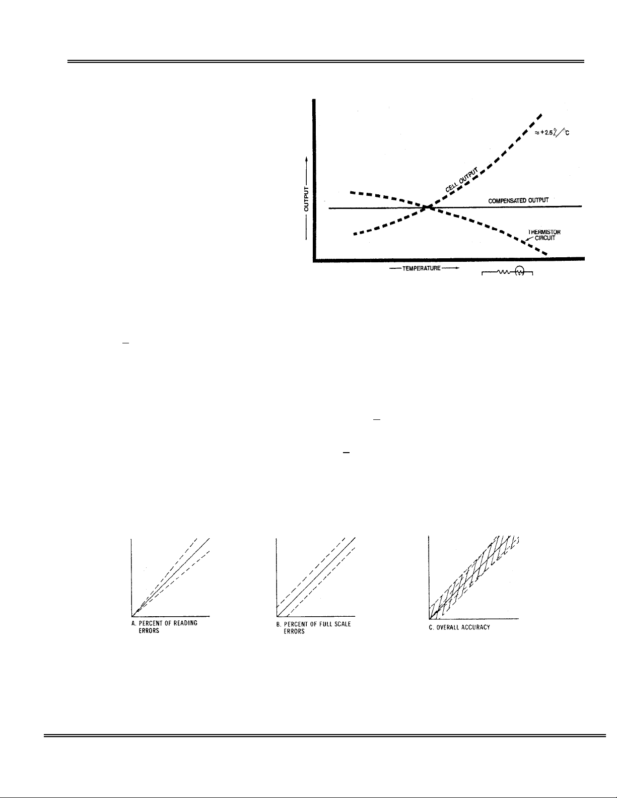
Temperature: The rate at which oxygen molecules diffuse into the sensor is controlled by a Teflon membrane
otherwise known as an 'oxygen diffusion limiting barrier. The fact that all diffusion processes are temperature
sensitive, the sensor's electrical output also varies with temperature. This variation is relatively constant (2.5% per
ºC change in temperature). A temperature compensation circuit employing a thermistor offsets this effect with an
5% or better (over the operating temperature range of the analyzer) and generates an output signal
accuracy of
that is virtually independent of small ambient temperature variation. To minimize error in oxygen measurement, the
calibration of the analyzer should be carried out as close as possible to the temperature during sampling. A small
temperature variation of ~10º F will produce < 2% error.
Accuracy:
1) 'Percent of reading errors', illustrated by Graph A below, such as +
compensation
2) 'Percent of full scale errors', illustrated by Graph B, such as +
tolerances in the electronic components, which are really minimal due to today's technology and the fact that other
errors are 'spanned out' during calibration.
Graph C illustrates these 'worse case' specifications that are typically used to develop an analyzer's overall accuracy
statement of < 1% of full scale at constant temperature or < 5% over the operating temperature range. QC testing
is typically < 1% prior to shipment.
Example 1: As illustrated by Graph A any error during a span adjustment, e.g., at 20.9% (air) of full scale range
would be multiplied by a factor of 4.78 (100/20.9) when used for measurements of 95-100% oxygen concentrations.
Conversely, an error during span adjustment at 100% of full scale range will be reduced proportionately for
measurements of lower oxygen concentrations. Refer to the Calibration section for additional details.
+
In light of the above parameters, the overall accuracy of an analyzer is affected by two factors:
5% inherited error in the temperature
circuit due to the tolerances of the resistors and thermistor.
1-2% linearity errors generally associated with
10
Page 13

Advanced Instruments Inc.
Mounting the Analyzer
The standard GPR-2600 is designed to be panel mounted and requires a cutout that accommodates the enclosure
and 4 mounting bolts. The design also lends itself to 19” rack mounting with an optional bezel or wall mount
enclosures as illustrated below.
1. The standard GPR-2600 is designed for panel mounting directly to any flat vertical surface, wall or bulkhead
plate with the appropriate cut out and four ¼” diameter holes for insertion of the mounting studs through the
front mounting bezel.
2. When mounting the analyzer, position it approximately 5 feet above the floor for better viewing purposes and
easy access to various functions of the analyzer. Leave sufficient room for access to the terminal connections at
the rear of the enclosure.
3. Note: The proximity of the analyzer to the sample point and use of optional sample conditioning components,
such as a sample cooling coil, a coalescing filter and or a particulate filter may have an impact on sample lag
time and hence the analyzer response time.
Four mounting holes on four corners to secure
analyzer on a flat vertical surface
11
Page 14

Advanced Instruments Inc.
Gas Connections
The GPR-2600 with its standard flow through configuration is designed for positive sample pressure and requires ¼”
compression type connections for incoming sample and outgoing vent lines.
The user is responsible for providing calibration gases and other optional components (if not purchased with the
analyzer).
Flow Control Valve: A flow control valve is mounted upstream of the sensor and provides means of controlling the
flow rate of the sample gas. Sample flow rate of 1-5 SCFH cause no appreciable change in the oxygen reading.
However, for optimum performance, a flow rate of 1-2 SCFH is recommended.
Analyzer with SS sensor housing, Flow control valve and
Flow Meter
12
Page 15

Advanced Instruments Inc.
Electrical Connections
Incoming power for the 100-250V AC powered analyzers is supplied through a universal power entry module. A
standard computer type power cord (Part# A-1008) is required for the universal power entry module. A well
grounded insulated power cable is recommended to avoid noise resulting from unwanted interference.
The appropriate AC power supply (110V or 220V) must specified be specified at order placement if the analyzer is to
be equipped with a temperature controlled heater system.
Power consumption is approximately 30 watts without optional heater and 150-200 watts with the heater system.
Caution: Integral 4-20mA converters are internally powered and do not require external power. DO NOT supply any
voltage to any of the terminals of the 4-20 mA signal output or the 4-20 mA range ID. If a power is supplied, the 420 mA chip can be permanently damaged.
Optional Range ID
The standard 1-5 VDC output is provided for range identification, as described below. An optional 4-20 mA or 5
independent relay contacts representing 5 ranges available as well. Check the QC certificate to verify the option(s).
The appropriate relay contact will close when a specific range is selected. The dry contacts are rated at 30VDC @ 1A.
The voltage or 4-20 mA Range ID; Range 1= 5V or 20 mA
Range 2 = 4V or 16 mA
Range 3 = 3V or 12 mA
Range 4 = 2V or 8 mA
Range 5 = 1V 0r 4 mA
13
Page 16

Advanced Instruments Inc.
Procedure for making connections
1. As illustrated above the alarm relays and signal output connections are hard wired to push-open type
terminal blocks located at the rear of the analyzer.
2. Use a small bladed screwdriver to push the lever down and insert the stripped end of the wire into the slot.
NOTE: Strip insulation of the wires no more than 3/16 inch in length.
3. Insert the stripped end of the cables into the appropriate terminal slots assuring no bare wire remains
exposed that could come in contact with the back panel of the analyzer enclosure.
4. Release the lever to secure the wires in the receptacle.
5. To connect to an active relay or “fail safe”, connect the live cable to the common terminal C and the
secondary cable to the normally open NO terminal.
6. To break the connection upon relay activation, connect the secondary cable to the normally closed NC
terminal.
Danger: While connecting the cables to the relay terminals, ensure there is no voltage on the cables to
prevent electric shock and possible damage to the analyzer.
Caution: Assure the stripped wire ends of the cable are fully inserted into the terminal slots and do not
touch each other or the back panel of the analyzer enclosure.
Oxygen Level Alarms
The analyzer is configured with two user adjustable threshold type alarm relays that can be configured in the field
from the ALARM option on the MAIN MENU as follows:
1. Establish independent alarm set points
2. Either Hi or Lo oxygen condition
3. Either On or Off (enabled or disabled)
Both alarms may be temporarily defeated using a user entered ‘timeout’ period (normally in minutes)
The alarm set point represents an oxygen value. When the oxygen reading exceeds (high alarm) or falls below (low
alarm) the alarm set point, the relay is activated and the LCD displays the alarm condition.
When activated, the alarm function triggers the corresponding SPDT Form C non-latching relay rated @ 5A, 30VDC or
240VAC resistive. To prevent chattering of the relays, a 2% hysteresis is added to the alarm set point. This means
that the alarm will remain active until the oxygen reading has fallen 2% below the alarm set point (high alarm) or
risen 2% above the alarm set point (low alarm) after the alarm was activated. The timeout feature is useful while
replacing the oxygen sensor or during calibration when the oxygen reading might well rise above the alarm set point
and trigger a false alarm.
Note: When making connections the user must decide whether to configure/connect Alarm 1 and Alarm 2 in failsafe
mode (Normally Open – NO – where the alarm relay de-energizes and closes in an alarm condition) or non-failsafe
mode (Normally Closed – NC – where alarm relay energizes and opens in an alarm condition).
Power/System Failure Alarm
A dry contact rated at 30VDC @ 1A is provided as a power/system failure alarm that activates when power supplied
to the analyzer’s circuits is interrupted. The contact is normally closed but opens when the power to the analyzer is
switched off or interrupted. The power fail alarm cannot be disabled.
0-1 VDC, 0-5 VDC and 4-20 mA Signal Output
The analyzer provides 0-1 VDC and 4-20mA full scale signal. The integral IC on the main PCB provides 4-20mA fully
isolated signals for output and optional 4-20 mA range ID. This IC does not require any external power.
Range ID
The standard range ID is designated with a voltage output corresponding to a specific range. For example, 5V
corresponds to the least sensitive range (25% on the GPR-2600 analyzer) and drops 1V for each additional range.
14
Page 17

Advanced Instruments Inc.
Optional 4-20 mA signal as range ID is also available. With 4-20 mA range ID option, 20mA represents the least
sensitive range and it drops by 4mA (16mA, 12mA, 8mA, 4mA) for each additional range. Please check the QC sheet
to confirm the range ID option ordered.
Relay contacts associated with each range may also be provided as range ID. With relay contacts as range ID, the
common pin of all relays is connected to the terminal marked COMM and five (5) normally open relay contacts that
close when the related range is active. The dry contacts are rated at 30VDC @ 1A.
Caution:
external voltage will permanently damage the 4-20mA converter.
The integral 4-20mA converters are internally powered and do not require external power. Applying any
Loss of Flow Alarm
The analyzer may be equipped with an optional integral loss of flow/low flow alarm. The alarm is set at 1.5 SCFH.
The contact will close when the gas flow exceeds 1.5 SCFH but will open when the gas flow falls below 1.5 SCFH.
The set point is relatively rough, therefore, to prevent false alarm, set the gas flow rate above 2 SCFH. Check the QC
certificate to verify whether this option is available with your analyzer.
The contact is rated at 1A@30 VDC. Do not exceed the recommended rating.
Temperature Controlled Heater System with Thermal Runaway Protection
The standard GPR-2600 Series analyzer is generally not equipped with the heater system. However, in anticipation of
very low % (less than 0.01 %) oxygen analysis, the user may elect to add the heater system. This unit is a PID
controller which operates between 0-99°F. At the factory the controller is programmed to maintain the temperature
at 85°F.
Caution: Do not change this setting. A higher
temperature setting may drastically reduce sensor life
and possibly cause damage to the electronic circuitry of
both the controller and the analyzer.
Warning:
the temperature controller is ON.
When power is applied to the temperature controller, the controller
tunes itself to eliminate and/or minimize the over/under shoot of
temperature from the set point. It is recommended that at initial
start-up, when replacing the oxygen sensor or when trouble
shooting, turn off the power to the heater (by setting the
temperature set point at 60°F to prevent overheating the analyzer).
When operating the analyzer under normal conditions, set the
temperature controller at 85⁰F.
Changing the display value from °F to °C:
1. Push the UP ARROW and ENTER buttons down for 5 seconds to access the SECURE MENU
2. Press INDEX to advance to the F-C MENU
3. Select °C or °F by pressing the UP ARROW key
4. Press the ENTER key when F-C starts flashing on the display
5. Press INDEX to exit the SECURE MENU
Heater Runaway Protection
Part of the optional temperature controlled heater system is a heater runaway protection circuit that protects the
electronics in the event the temperature controller should fail and thereby allowing the heater to runaway damaging
the components inside the analyzer.
The runaway protection is provided by a J2 type device positioned between the temperature controller and the
heater. This device cuts-off power to the heater if the temperature inside the analyzer exceeds 70°C. Should the J2
device cut power to the heater, correct the problem and reset the runaway protector device (J2 will conduct under
Keep the front door securely fastened and closed when
15
Page 18

Advanced Instruments Inc.
normal conditions) by exposing it to 0°C for a few minutes (a refrigerator freezer will do). NOTE, should the J2 fail to
reset itself, replace it.
To access the J2, remove the back cover of the analyzer. The j2 is mounted
on a white terminal block as shown in the figure above.
J2 device
Installing a new Oxygen Sensor
The analyzer is equipped with an internal oxygen sensor that has been tested and calibrated by the manufacturer
prior to shipment and is fully operational from the shipping containers. The sensor has been installed at the factory.
However, it may be necessary to install the sensor in the field.
Caution: DO NOT open/dissect the sensor. The sensor contains a corrosive liquid electrolyte that could be harmful
if touched or ingested, refer to the Material Safety Data Sheet contained in the Owner’s Manual appendix. Avoid
contact with any liquid or crystal type powder in or around the sensor or sensor housing, as either could be a form of
electrolyte. Leaking sensors should be disposed of in manner similar to that of a common battery in accordance with
local regulations.
Oxygen screws in to a SS or Delrin flow through sensor housing. Screw sensor only finger tight.
16
Page 19

Advanced Instruments Inc.
Establishing Power to the Electronics
Once the power to the electronics is established, the digital display responds instantaneously. When power is applied,
the analyzer performs several diagnostic system status checks termed “SYSTEM SELF TEST” as illustrated below:
System Self Test
CPU
Memory
RTC
Analog
GPR Series Oxygen Analyzer
Software Version X.XX
Advanced Instruments
2855 Metropolitan Place
Pomona, CA 91767
Tel: 909-392-6900
Fax: 909-392-3665
e-mail: info@aii1.com
After 3 seconds the system defaults to the STANDBY mode and the LCD displays the following:
OK
OK
OK
OK
* MAIN MENU
Sample
Span
Zero
Alarm
System
Standby
Auto Range
85⁰F 100Kpa
Standby
12/31/07 12:00:00
Menu Format
Following selections are available from the main Menu
• Menu selected – displayed on the top line in the upper left corner of the display.
• Menu options available – all menus displayed on the left side of the LCD.
• Menu option selected - indicated by the cursor (*) positioned to the left of the menu option selected.
• System mode - indicated at the top center of the display.
17
Page 20

Advanced Instruments Inc.
• Range mode and current auto or fixed manual range - displayed on the first line at the bottom of the
display.
• Temperature inside of the analyzer and ambient pressure - displayed on the second line at the bottom of
the screen.
Note:
Menu Navigation
The four (4) pushbuttons located on the front of the analyzer control the system Menus
Green - ENTER (select)
Yellow UP ARROW – advance cursor up
Yellow DOWN ARROW – advance cursor down
Red – ESC (menu)
Select the Menu option by advancing cursor (*) by repeatedly pressing the yellow UP/DOWN ARROW keys.
Accept the Menu option selected with cursor (*) by pressing the green ENTER key.
Abort the Menu option selected with cursor (*) and return to the previous menu by pressing the red ESC key.
NOTE: If a selection is not made within 30 sec, the analyzer will return to Sample Mode.
In the event power to the analyzer is interrupted, the system defaults to the “Standby” mode when power
is restored. To resume sampling, advance the cursor (*) to “Sample” mode, press ENTER to select and
select the range mode as described below.
Range Mode Selection
Advance the cursor (*) to the “Sample” option as illustrated and press the green ENTER key to accept the selection.
MAIN MENU
* Sample
Span
Zero
Alarm
System
Standby
Auto Range
85⁰F 100Kpa
The following menu appears:
* SAMPLE
Auto Range
Manual Range
Bypass
Standby
Auto Range
85⁰F 100Kpa
Standby
12/31/2011 12:00:00
Standby
12/31/2011 12:00:00
18
Page 21

Advanced Instruments Inc.
The analyzer is equipped with four (4) standard measuring ranges (see specification) and provides users with a
choice of sampling modes. By accessing the MAIN MENU, users may select either the Auto Range or a fixed Manual
Range mode.
Auto Range Sampling
In the Auto Range mode, the analyzer will automatically select the appropriate full scale range depending on the
concentration of oxygen in a sample gas. The display will shift to the next higher range when the oxygen reading
exceeds 99.9% of the current range. The display will shift to the next lower range when the oxygen reading drops to
85% of the next lower range.
For example, if the analyzer is reading 1% on the 0-10 % range and an upset occurs, the display will shift to the 025% range when the oxygen reading exceeds 10%. Conversely, once the upset condition is corrected, the display
will shift back to the 0-10% range when the oxygen reading drops to 8.5%.
Procedure: From the SAMPLE menu, advance the cursor (*) to the “Auto Range” option and press ENTER:
SAMPLE
* Auto Range
Manual Range
Bypass
Standby
Auto Range
85⁰F 100Kpa
Note: For an optional automated Sample System, the system displays a message "Opening Sample Valve". This
message does not apply to analyzers equipped with standard manually operated Sample System.
Similarly, the Bypass and Standby modes do not apply to analyzers equipped with manual Sample System
Within seconds the system assesses the oxygen concentration, selects the appropriate range (as described above)
and returns to the MAIN MENU in the “Sample” mode. On the second line from the bottom of the menu screen, the
Auto Range mode is indicated along with the current full scale range.
* MAIN MENU
Sample
Span
Zero
Alarm
System
Standby
Auto Range
85⁰F 100Kpa
Standby
12/31/2011 12:00:00
Sample
5.00 %
0 to 10 %
12/31/2011 12:00:00
19
Page 22

Advanced Instruments Inc.
Manual Range Sampling
In the manual range mode, the display will not shift automatically. Instead, when the oxygen reading exceeds 125%
of the upper limit of the current range, an” OVER RANGE” warning will be displayed. Once the OVER RANGE warning
appears the user must advance the analyzer to the next higher range.
Procedure: From the SAMPLE menu, advance the cursor (*) to the “Manual Range” option and press ENTER:
SAMPLE
Auto Range
* Manual Range
Bypass
Standby
Auto Range
85⁰F 100Kpa
The following display appears:
MANUAL RANGE
0 to 25%
0 to 10%
0 to 5%
* 0 to1 %
Auto Range
85⁰F 100Kpa
Advance the cursor (*) to the desired fixed manual range, e.g. 0 to 1% and press ENTER.
Within seconds the system assesses the oxygen concentration and returns to the MAIN MENU in the “Sample” mode.
On the second line at the bottom of the menu, the Manual Range mode is indicated along with the fixed full scale
range selected
Sample
12/31/2011 12:00:00
Sample
12/31/2011 12:00:00
* MAIN MENU
Sample
Span
Zero
Alarm
System
Standby
Manual Range
85⁰F 100Kpa
Sample
5.00 %
0 to 10 %
12/31/2011 12:00:00
20
Page 23

Advanced Instruments Inc.
If the oxygen reading exceeds 125% of the full scale fixed range manually selected, the system displays the
following message, e.g., on 0-10 % range:
* MAIN MENU
Sample
Span
Zero
Alarm
System
Standby
Manual Range
85⁰F 100Kpa
Sample
12.50 %
OVER RANGE
0 to 10 %
12/31/2011 12:00:00
Setting Alarms
The analyzer is configured with two user adjustable threshold type alarm relays that can be configured in the field
from the ALARM option on the MAIN MENU as follows:
¾ Establish independent oxygen set points
¾ Either Hi or Lo
¾ Either On or Off (enabled or disabled)
¾ Both temporarily defeated using a user entered ‘timeout’ period (normally a few minutes)
The alarm set point represents a value. When the oxygen reading exceeds (high alarm) or falls below (low alarm) the
alarm set point, the relay is activated and the LCD displays the alarm condition.
When activated the alarms trigger SPDT Form C non-latching relays @ 5A, 30VDC or 240VAC resistive. To prevent
chattering of the relays, a 2% hysteresis is added to the alarm set point. This means that the alarm will remain active
until the oxygen reading has fallen 2% below the alarm set point (high alarm) or risen 2% above the alarm set point
(low alarm) after the alarm was activated. The timeout feature is useful while replacing the oxygen sensor or during
calibration when the oxygen reading might well rise above the alarm set point and trigger a false alarm.
Note: When making connections the user must decide whether to configure/connect Alarm 1 and Alarm 2 in failsafe
mode (Normally Open – NO – where the alarm relay de-energizes and closes in an alarm condition) or non-failsafe
mode (Normally Closed – NC – where alarm relay energizes and opens in an alarm condition).
Procedure: Advance the cursor (*) to the “Alarm” option and press the green ENTER key to accept the selection.
MAIN MENU
Sample
Span
Zero
* Alarm
System
Standby
Auto Range
85⁰F 100Kpa
Sample
5.00 %
0 to 10 %
12/31/2011 12:00:00
21
Page 24

Advanced Instruments Inc.
The following menu appears:
ALARM Sample
* Set Alarm 1
Set Alarm 2
Alarm 1 HI
Alarm 2 LO
Alarm 1 ON
Alarm 2 OFF
Alarm Timeout
Auto Range 0 to 10 %
85⁰F 100Kpa 12/31/2011 12:00:00
Advance the cursor (*) to the “Set Alarm 1” option and press the green ENTER key to accept the selection.
Sample
020 %
Press UP or DOWN
to change value
ENTER to Save
ESC to Return
Set Alarm 1 in %
Auto Range 0 to 10 %
85⁰F 100Kpa 12/31/2011 12:00:00
Follow selection of set point, press the ENTER key to save the alarm value or ESC to return to the MAIN MENU.
Within a few seconds after pressing the ENTER key, the system returns to the MAIN MENU.
Repeat the above steps for “Set Alarm 2”.
Configure Alarm 1 and Alarm 2 as High or Low by advancing the cursor (*) to the desired feature as illustrated
below.
ALARM Sample
Set Alarm 1
Set Alarm 2
* Alarm 1 HI
Alarm 2 LO
Alarm 1 ON
Alarm 2 OFF
Alarm Timeout
Auto Range 0 to 10 %
85⁰F 100Kpa 12/31/2011 12:00:00
Press the ENTER key to toggle between the settings: HI and LO and/or ON and OFF.
Pressing the ENTER key will toggle the selection and the system will return to the MAIN MENU.
22
Page 25

Advanced Instruments Inc.
ALARM TIMEOUT: The Alarm Timeout feature allows the user to select a “time delay” to prevent the alarm from
triggering relay immediately after the alarm condition occurs. The time delay feature allows the user from triggering
a false alarm during maintenance or self induces signal spike. In order to enter the time delay, advance the cursor
(*) to the “Alarm” option and press the green ENTER key to accept the selection.
MAIN MENU
Sample
Span
Zero
* Alarm
System
Standby
Auto Range
85⁰F 100Kpa
The following menu appears:
ALARM Sample
*Set Alarm 1
Set Alarm 2
Alarm 1 HI
Alarm 2 HI
Alarm 1 ON
Alarm 2 ON
Alarm Timeout
Auto Range 0 to 10 %
85⁰F 100Kpa 12/31/2011 12:00:00
Advance the cursor (*) to the “Alarm Timeout” option and press the green ENTER key to accept the selection.
The following menu appears:
Sample
5.00 %
0 to 10 %
12/31/2011 12:00:00
Sample
0 MIN
0
Press UP or DOWN
to change value
ENTER to Save
ESC to Return
Alarm Delay in Minutes
Auto Range 0 to 10 %
85⁰F 100Kpa 12/31/2011 12:00:00
Follow the prompt above and press the ENTER key to save the alarm timeout value or ESC to return to the MAIN
MENU.
Within a few seconds after pressing the ENTER key, the system returns to the MAIN MENU.
23
Page 26

Advanced Instruments Inc.
System Menu
The analyzer is equipped with a wide range of features that enables users to enhance performance and tailor their
interface with the analyzer. The SYSTEM menu shown below lists the features available and is followed by a
description of each function. Most of the functions are initiated by toggling between options by pressing the ENTER
key as previously described.
Advance the cursor (*) to the “Alarm” option and press the green ENTER key to accept the selection.
MAIN MENU
Sample
Span
Zero
Alarm
* System
Standby
Auto Range
85⁰F 100Kpa
The following menu appears:
* SYSTEM
Enable Low Flow Alarm
Disable Alarm During Cal
Signal Average
Range
Logging Interval
Temp Coefficient
View Data Graph
Set Clock (and Date)
Logging ON
Show Text
Display Negative (Reading) ON
Advance the cursor (*) to the desired option, press ENTER key and follow the instructions below.
Enable Low Flow Alarm If the analyzer is equipped with a low flow alarm, press ENTER key to toggle
Disable Alarm During Cal Press ENTER key to toggle between ENABLE and DISABLE.
Signal Average Press ENTER key to select and choose Low, Medium (default) or High –
Range Same as Auto/Manual Range option found on SAMPLE menu.
Logging Interval Press ENTER key and a display appears similar to Alarm Timeout above for the
Sample
5.00 %
0 to 10 %
12/31/2011 12:00:00
between ENABLE and DISABLE (this feature is currently not controlled by the
microprocessor).
functions allows users to select their preference regarding the trade-off of
response time vs. noise filtering. The signal averaging is roughly 5, 8 and 10
seconds when selecting LOW, MEDIUM OR HIGH option
user to enter the interval in minutes for capturing data points for logging
purposes.
24
Page 27

Advanced Instruments Inc.
Temp Coefficient Enables the user to fine tune the temperature compensation (this feature is an
option, consult factory for more details).
View Data Graph Provided that the “Logging” feature is toggled ON, selecting this feature
provides a full-screen display or graph of the data points in the analyzer
memory.
Set Clock (and Date) Selecting this option generates a display for selecting Time or Date with each
followed by a detailed display for setting hour, minute, second or year, month,
day.
Logging Press ENTER key to toggle between ON and OFF. With Logging ON, the
analyzer will store the data in its internal memory. The internal memory is
limited to 32K. The total number data points that can be stored are 5500.
Depending on the time interval between the points selected, the data can be
stored from a few days to several weeks.
Show Text Press ENTER key to toggle between “Text and Graph” display options:
1.) With Show Text option, large numbers of gas concentration (as
illustrated herein)
2.) Show Graph option, small numbers and a small graphical trend of O2
reading. The Graph only shows a limited number of data points. After
the graph has filled the limited space on the LCD, the graph will
refresh itself by “First in First out” methodology. This feature allows
the user to look at trending of the data when installing a new sensor,
after calibration or after a process upset condition.
Display Negative (Reading) Press the ENTER key to toggle between ON and OFF. With “Display Negative”
ON, the analyzer will show negative numbers on the screen in the event sensor
shows a negative reading.
25
Page 28

Advanced Instruments Inc.
Installation & Start-up is now complete . . . Proceed to
calibrate the Analyzer
The electrochemical oxygen sensors manufactured by Analytical Industries Inc. (dba Advanced Instruments)
generate an electrical current that is linear or proportional to the oxygen concentration in the sample gas. In the
absence of oxygen the sensor exhibits an absolute zero, e.g. the sensor does not generate a current output in the
absence of oxygen. Given the properties of linearity and an absolute zero, single point calibration is possible.
As described below, zero calibration is recommended only when the application (or user) demands optimum accuracy
for analysis below 5% of the most sensitive or lowest range available on the analyzer. Span calibration in one of the
forms described below is sufficient for all other measurements.
Zero Calibration
Despite the absolute zero inherent in electrochemical oxygen sensors, the reality is that analyzers can display an
oxygen reading when sampling a zero gas due to:
¾ Contamination or quality of the zero gas
¾ Minor leakage in the sample line connections
¾ Residual oxygen dissolved in the sensor’s electrolyte
¾ Tolerances of the electronic components
The zero capability of every analyzer is qualified prior to shipment. However, because the factory sample system
conditions differ from that of the user, no ZERO OFFSET adjustment is made to the analyzer by the factory
NOTE: zero calibration is recommended only when the application (or user) demands optimum accuracy for analysis
below 5% of the most sensitive or lowest range available on the analyzer
Span Calibration
Involves periodically checking and/or adjusting the electronics to the sensor’s signal output at a given oxygen
standard or a span gas. To minimize error due to ambient temperature variations, span calibration of the analyzer
must be done as close as possible to the sampling temperature conditions. The frequency of calibration varies with
the application conditions; the degree of accuracy of the measurement required. However, the interval between span
calibrations should not exceed one (1) months.
Note: Regardless of the oxygen concentration of the standard used, the span calibration process takes
approximately 10-15 minutes
Menu Functions - Zero Calibration
Factory Default Zero: The feature eliminates any previous zero calibration offset adjustment stored in
the analyzer memory.
This factory default calibration is recommended before performing a ZERO
CALIBRATION or when troubleshooting the analyzer. The factory default zero
calibration is not recommended when subsequent periodic SPAN CALIBRATION is
done.
Zero Calibration: Recommended for optimum accuracy. The user must ascertain that the oxygen
reading has reached a stable value and is below 50% of the most sensitive or
lowest range available on the analyzer to perform a ZERO CALIBRATION.
If the user attempts to initiate the ZERO CALIBRATION function while the oxygen
26
Page 29

Advanced Instruments Inc.
reading is above 50% of the most sensitive or lowest range, the system displays
the message “CALIBRATION FAILED” and returns to the “Sample” mode.
Menu Functions - Span Calibration
Factory Default Span: The system eliminates any previous span calibration adjustment stored in the
analyzer memory and displays an oxygen reading within +50% of the span gas
value currently flowing through the analyzer.
If the oxygen reading is outside +
perform Span calibration will result in “CALIBRATION FAILED” message and the
analyzer will return to the “Sample” mode. This feature allows the user to test
the sensor’s signal output without removing it from the sensor housing.
This function is recommended before performing a SPAN CALIBRATION or
when troubleshooting an analyzer.
Span Gas Units/Value:
Span Calibration: The user must ascertain that the oxygen reading has reached a stable value
After initiating either Auto or Manual Span from the SPAN CALIBRATION menu,
the system produces a display prompting the user to select span gas in %
units, which is followed by a second display prompting the user to enter a
numerical span gas value.
before completing Span Calibration. A premature Span calibration will result in
inaccurate results.
50% of the span gas value, the attempt to
Calibration Procedure – Span Calibration
To perform Span calibration
1. Assure that the analyzer is in the Auto Range mode as described above.
2. Span gas is connected to the SPAN IN port at the rear of the analyzer (optional feature). If a separate span
port is not available, disconnect the sample gas line and connect the span gas line
3. Set the span gas pressure between 5-30 PSIG and set the flow at 1-2 SCFH
4. Allow the analyzer reading to stabilize before attempting calibration.
5. From Main Menu, Advance the cursor (*) to the “Span” option as illustrated and press the green ENTER key
to accept the selection.
MAIN MENU
Sample
* Span
Zero
Alarm
System
Standby
Auto Range
85⁰F 100Kpa
Sample
1.00 %
0 to 10 %
12/31/2011 12:00:00
27
Page 30

Advanced Instruments Inc.
The following menu appears:
SPAN
* Factory Default
Calibrate
Auto Range 0 to 10 %
85⁰F 100Kpa 1/31/2011 12:00:00
Advance the cursor (*) to the Calibrate and then select Manual Span option and press ENTER. The following screen
will appear prompting the user to select calibration gas unit. Select %
SPAN GAS
* Enter as %
Auto Range 0 to 1%
85⁰F 100Kpa 12/31/2011 12:00:00
After selecting the calibration gas units, following screen will appear; the analyzer will switch to the appropriate
range depending on the span gas value entered.
0.90 %
2
Press UP or DOWN keys to change values
Select ENTER to save, ESC to return to previous digit
Auto Range 0 to 25 %
85⁰F 100Kpa 12/31/2011 12:00:00
After accepting the span gas value, the display will show the following message
Opening Span valve and then will purge the span line for 30 sec (this is a built in feature for purging the sapn gas
line whether a separate span port is available or not (applies to analyzers with sample system equipped with
auto/pneumatic sample/span/zero valves) .
28
Page 31

Advanced Instruments Inc.
Note: When span valve opens, assure that the gas flow is the same as was set for Sample gas. Further, the analyzer
might show positive spike on the signal due to excessive oxygen in the span gas line (due to minor leakage in the
gas line, oxygen from air diffuses into the gas line even though the span gas line is under pressure) but within a few
minutes the excessive oxygen will purge out of the system and the analyzer will begin to analyze the true oxygen
content of the span gas.
Span
Calibration in
Progress. . .
20.90 20.7 %
SPAN GAS ACTUAL O2 VALUE
ENTER TO CAL ESC TO ABORT . . .
After the oxygen reading has stabilized, press ENTER to complete the Span Calibration (if Manual Span option was
selected). If the user attempts to complete the SPAN CALIBRATION function while the oxygen reading is outside the
+/-50% of the span gas value entered, the system displays the message “CALIBRATION FAILED” and returns to the
“Sample” mode.
Auto Span Calibration
In the Auto Span mode, the micro processor will watch the trending of the oxygen reading. When the reading has
stabilized and is within +/-50% of the span gas value entered, the micro will adjust the oxygen reading to match
with the span gas value and return to the Sample mode and start displaying the true oxygen reading in the sample
gas. The Auto Calibration process may take from a few minutes to more than an hour (depending on the level of
oxygen contamination of the span gas line).
After completing the Auto Calibration, the system returns to the MAIN MENU in the “Sample” mode and displays the
real time oxygen contents in the sample gas. The oxygen value will slowly trend down from the span gas value.
MAIN MENU
* Sample
Span
Zero
Alarm
System
Standby
Auto Range
85⁰F 100Kpa
Sample
8.00 %
0 to 10 %
12/31/2011 12:00:00
Calibration Procedure – Zero Calibration
To perform Zero calibration
1. Ensure that the analyzer is in the Auto Range mode as described above.
2. Ensure a good quality Zero gas is flowing through the analyzer.
3. Assure there are no restrictions in vent line.
4. Regulate the Zero gas pressure between 5-30 PSIG and set the flow rate to 1-2 SCFH.
5. Allow the analyzer reading to stabilize below 50% of the lowest range available on the analyzer before
attempting Zero calibration.
29
Page 32

Advanced Instruments Inc.
Advance the cursor (*) to the “Zero” option as illustrated and press the green ENTER key to accept the selection.
MAIN MENU
Sample
Span
* Zero
Alarm
System
Standby
Auto Range
85⁰F 100Kpa
The following menu appears:
ZERO Sample
* Factory Default
Auto
Manual
Zero Cal Interval
Timed Zero OFF
Time Zero Cal in 21 Days
Cal will occur at 14.16
Last Cal Passed
Auto Range 0 to 10 %
85⁰F 100Kpa 12/31/2011 12:00:00
Advance the cursor (*) to the Auto or Manual Zero option and press ENTER. The microprocessor will open/energize
the Zero gas solenoid valve and allow the Zero gas to flow through the analyzer (analyzers equipped with pneumatic
sample/span/zero valves). For analyzers without pneumatic valves, allow the zero gas to flow through the analyzer.
Advance the cursor (*) to the “Manual Zero” option and press the green ENTER key to accept the selection.
The following menu with current oxygen value appears:
Sample
5.00 %
0 to 10 %
12/31/2011 12:00:00
Zero
Calibration
in
Progress
0.05 %
ENTER to Cal, ESC to Abort
After the oxygen reading has stabilized, press ENTER to complete the Zero Calibration (if Manual Zero option was
selected). If the user attempts to initiate the ZERO CALIBRATION function while the oxygen reading is above 50% of
the most sensitive or lowest range, the system displays the message “CALIBRATION FAILED” and returns to the
30
Page 33

Advanced Instruments Inc.
“Sample” mode. In the Auto Zero mode, the micro processor will watch the trending of the oxygen reading. When
the reading has stabilized and is within 50% of the allowed limit, the micro will offset the oxygen reading and return
to the Sample mode and display the true oxygen reading.
After Zero calibration, the “CALIBRATION FAILED or CALIBRATION PASSED” message will appear.
Note: With Auto calibration routine, the micro processor will watch the downward trend and wait until the change in
slope of the downward trend approaches zero (no further drop in the oxygen reading).
NOTE: Zero calibration will pass only if the zero offset had reached less than 50% of the most sensitive range. If
the zero offset remains above the 50% of the most sensitive range (but the downward trend had stabilized), the
Zero calibration will fail and the analyzer will return to the Sample mode. A message “Failed Cal” will appear on the
main display.
AII Configuration Software
AII Configuration Software
software can be used to perform Zero and Span calibration, select ranges, set alarms and so on. Should you need
this software, contact factory.
Analog Output Adjustment
Although the analog signal output (0-1 V or 4-20 mA) has been tested and matches the analyzer display, in rare
cases, the analog signal output may not match with the analyzer display. However, the analog signal output may be
adjusted in the field by using
must be installed on a PC and connected to the USB port of the analyzer to make analog signal output adjustment. A
procedure to use the configuration software is provided with the software. Should you need a copy, consult factory.
is available to access all analyzer functions through a PC via a USB connection. This
AII Configuration Software
, available free of charge. The configuration software
31
Page 34

Advanced Instruments Inc.
Normal Sampling
After installation and calibration is complete, select the Sample from the main Menu. Choose the Auto or Manual
range option. The analyzer will immediately begin to analyze the gas sample and display the real time oxygen
concentration on the screen.
When switching sample gas streams, a sudden spike in the analyzer signal might appear. Allow sufficient time to the
analyzer to stabilize before starting to collect the real time analysis data. The analyzer data may be stored in the
internal analyzer memory or recorded on a recording device by using the 0-1V or 4-20 mA analog signal. When
connecting the analog output to an external recording device, limit the length of cable to less than 6 feet. If possible,
use a shielded cable with the shield connected to the ground of the recording device.
Standby
¾ The analyzer has no special storage requirements.
¾ The sensor should remain inside of the sensor housing and connected with the analyzer electronics during
storage periods.
¾ Turn the Sample/Bypass valve to Bypass position
¾ Store the analyzer with the power OFF.
¾ If storing for an extended period of time, protect the analyzer, cable and the sensor housing (with external
sensor option) from dust, excessive heat (no more than 45 degree C) and moisture (non condensing
atmosphere).
6. Maintenance
There are no moving parts in the analyzer given the modular nature of the electronics and sensor. Cleaning the
electrical contacts when replacing the sensor is the extent of the maintenance required.
Serviceability: Except for replacing the oxygen sensor, there are no parts inside the analyzer for the operator to
service. Only trained personnel with the authorization of their supervisor should conduct maintenance.
Sensor Replacement
Periodically, the oxygen sensor will require replacement. The operating life is determined by a number of factors that
are influenced by the user and therefore difficult to predict. The sections dealing with Specification and Installation
Considerations define the normal operating conditions and expected life of the standard sensor utilized by the GPR2600 analyzer. As a general guideline, expected sensor life is inversely proportional to changes in oxygen
concentration, pressure and temperature.
The signal output of a PPM sensor (GPR-11-32-4 OR XLT-12-24-) in air ranges from 40 uA to 55 uA. You may check
the sensor output of a sensor by using an ammeter (set ammeter in the micro-amp mode and connect the com of
the meter to the inner gold contact and the mA/uA of the meter to the outer gold contact at the back of the sensor).
If the output of the sensor in air is not within the expected range, do not install the sensor. Install a new sensor and
send the defective sensor to factory for warranty evaluation.
Caution: DO NOT open the oxygen sensor. The sensor contains a corrosive liquid electrolyte that could be harmful if
touched or ingested, refer to the Material Safety Data Sheet contained in the Owner’s Manual appendix. Avoid
contact with any liquid or crystal type powder in or around the sensor or sensor housing, as either could be a form of
electrolyte. Leaking sensors should be disposed of in accordance with local regulations.
32
Page 35

Advanced Instruments Inc.
7. Spare Parts
Recommended spare parts for the GPR-2600 Oxygen Analyzer include:
Item No. Description
GPR-11-32-4 % Oxygen Sensor
XLT-11-24-4
GPR-11-32
XLT-11-24
Other spare parts:
A-3015
CTRL-1004
HTR-1002 Heater 110VAC
HTR-1003 Heater 220VAC
MTR-1008 Meter Digital Panel LCD Backlight
A-1146-E-40
A-1147-E-40
A-1174-40C PCB Assembly Power Supply with Dry contacts as Range ID
SNSR-1006 RTD Temperature Sensor
SNSR-1002 Thermal Runaway Protector J-2 Sensor
% Oxygen Sensor for Sample containing CO2
% oxygen sensor with optional sensor with SS housing
% oxygen sensor with optional sensor with SS housing for sample with CO2
Flow Through SS Housing
Controller Temperature PID
PCB Assembly Main / Display
PCB Assembly Power Supply
33
Page 36

Advanced Instruments Inc.
8. Troubleshooting
Symptom Possible Cause Recommended Action
Slow recovery
90 % Response time
slow
O2 reading doesn’t
agree with expected
O2 values
Erratic, negative or no
O2 reading possibly
accompanied by
electrolyte leakage
1. At installation, sensor was
exposed to air for too
long.
2. Defective sensor
3. excessive, dead volume in
sample line
4. contaminated sample gas
due to leakage in sample
line connections
5. Sensor damaged in service
due to prolonged exposure
to air or electrolyte
leakage
6. Sensor nearing end of life
1. Increased dead legs or
distance of sample line
2. low flow rate
1. Pressure and temperature
of the sample is varying
2. Abnormality in sample gas
3. Liquid covering sensing
area of sensor
4. Presence of interference
gases
5. Unauthorized maintenance
done
6. Sensor nearing end of life
1. Pressurizing the sensor by
flowing gas to the sensor
with the vent restricted
and suddenly removing
the restriction draws a
vacuum on the sensor,
causing electrolyte leakage
2. Contaminated sample or
exhausted O2 sensor
1. Replace sensor
2. If recovery unacceptable or O
fails to reach 50% of lowest range after
48-72 hours of installation of sensor,
check gas connections and gas integrity
before replacing sensor again
3. Leak test the entire sample system:
4. Vary the flow rate (1-5 SCFH); O
reading that changes inversely to the
changes in flow rate indicates a leakage
in the sample system bringing gas to
the analyzer
5. Correct source of leak
6. Replace sensor
1. Reduce dead volume by reducing
sample tube length
2. Increase flow rate
1. Calibrate the analyzer at the sample
temperature, pressure and flow.
2. Confirm O2 contents of sample gas
Consult factory
3. Clean sensor's sensing surface
4. Replace sensor, contact factory for
sample conditioning
5. Contact factory
6. Replace sensor
Replace sensor
Replace sensor, condition sample gas
reading
2
2
34
Page 37

,
O2 reading drifts
slowly upward
span requires large
gain adjustment
O2 reading swings too
much with minor
variation in ambient
temperature
The O2 reading
freezes even though
O2 in sample is
changing.
No O2 reading with
known O2 sample
gas.
“SENSOR” message
appears after Span
calibration
1. Sensor is nearing end of
its useful life
1. Low sensor output signal
possibly due to moisture
condensation on sensor
from liquid in sample gas
or electrolyte leakage from
sensor
2. Presence of interference
gases, e.g., ,Cl
Software bug
Software bug
Defective O2 sensor
Sensor output below the
recommended range
Advanced Instruments Inc.
1. Replace sensor
1. Ensure there is no condensable moisture
in the sample gas. Flow sample gas for
2-3 hours to flush moisture from sample
system
2. Consult factory
HCl, H2S
2
Contact factory
Contact factory
Replace O2 sensor
Replace sensor
35
Page 38

Advanced Instruments Inc.
9. Warranty
The design and manufacture of GPR Series oxygen analyzers, monitors and oxygen sensors are performed under a
certified Quality Assurance System that conforms to established standards and incorporates state of the art materials
and components for superior performance and minimal cost of ownership. Prior to shipment every analyzer is
thoroughly tested by the manufacturer and documented in the form of a Quality Control Certification that is included
in the Owner’s Manual accompanying every analyzer. When operated and maintained in accordance with the Owner’s
Manual, the units will provide many years of reliable service.
Coverage
Under normal operating conditions, the monitor, analyzers and sensor are warranted to be free of defects in
materials and workmanship for the period specified in accordance with the most recent published specifications, said
period begins with the date of shipment by the manufacturer. The manufacturer information and serial number of
this analyzer are located on the rear of the analyzer. Advanced Instruments Inc. reserves the right in its sole
discretion to invalidate this warranty if the serial number does not appear on the analyzer.
If your Advanced Instruments Inc. monitor, analyzer and/or oxygen sensor is determined to be defective with respect
to material and/or workmanship, we will repair it or, at our option, replace it at no charge to you. If we choose to
repair your purchase, we may use new or reconditioned replacement parts. If we choose to replace your Advanced
Instruments Inc. analyzer, we may replace it with a new or reconditioned one of the same or upgraded design. This
warranty applies to all monitors, analyzers and sensors purchased worldwide. It is the only one we will give and it
sets forth all our responsibilities. There are no other express warranties. This warranty is limited to the first customer
who submits a claim for a given serial number and/or the above warranty period. Under no circumstances will the
warranty extend to more than one customer or beyond the warranty period.
Limitations
Advanced Instruments Inc. will not pay for: loss of time; inconvenience; loss of use of your Advanced Instruments
Inc. analyzer or property damage caused by your Advanced Instruments Inc. analyzer or its failure to work; any
special, incidental or consequential damages; or any damage resulting from alterations, misuse or abuse; lack of
proper maintenance; unauthorized repair or modification of the analyzer; affixing of any attachment not provided
with the analyzer or other failure to follow the Owner’s Manual. Some states and provinces do not allow limitations
on how an implied warranty lasts or the exclusion of incidental or consequential damages, these exclusions may not
apply.
Exclusions
This warranty does not cover installation; defects resulting from accidents; damage while in transit to our service
location; damage resulting from alterations, misuse or abuse; lack of proper maintenance; unauthorized repair or
modification of the analyzer; affixing of any label or attachment not provided with the analyzer; fire, flood, or acts of
God; or other failure to follow the Owner’s Manual.
Service
Call Advanced Instruments Inc. at 909-392-6900 (or e-mail info@aii1.com) between 7:30 AM and 5:00 PM Pacific
Time Monday thru Thursday or before 12:00 pm on Friday. Trained technicians will assist you in diagnosing the
problem and arrange to supply you with the required parts. You may obtain warranty service by returning you
analyzer, postage prepaid to:
Advanced Instruments Inc.
2855 Metropolitan Place
Pomona, Ca 91767 USA
Be sure to pack the analyzer securely. Include your name, address, telephone number, and a description of the
operating problem. After repairing or, at our option, replacing your Advanced Instruments Inc. analyzer, we will sh ip
it to you at no cost for parts and labor.
36
Page 39

Advanced Instruments Inc.
10. MSDS Material Safety Data Sheet
Product Identification
Product Name Oxygen Sensor Series - PSR, GPR, AII, XLT
Synonyms Electrochemical Sensor, Galvanic Fuel Cell
Manufacturer Analytical Industries Inc., 2855 Metropolitan Place, Pomona, CA 91767 USA
Emergency Phone Number 909-392-6900
Preparation / Revision Date January 1, 1995
Notes Oxygen sensors are sealed, contain pro tective cov erings and in normal c onditions do not present a
Specific Generic Ingredients
Carcinogens at levels > 0.1% None
Others at levels > 1.0% Potassium Hydroxide or Acetic Acid, Lead
CAS Number Potassium Hydroxide = KOH 1310-58-3 or Acetic Acid = 64-19-7, Lead = Pb 7439-92-1
Chemical (Synonym) and Family Potassium Hydroxide (KOH) – Base or Acetic Acid (CH
General Requirements
Use Potassium Hydroxide or Acetic Acid - electrolyte, Lead - anode
Handling Rubber or latex gloves, safety glasses
Storage Indefinitely
Physical Properties
Boiling Point Range
Melting Point Range
Freezing Point
Molecular Weight KOH = 56 or Acetic Acid – NA, Lead = 207
Specific Gravity
Vapor Pressure
Vapor Density KOH – NA or Acetic Acid = 2.07
pH KOH > 14 or Acetic Acid = 2-3
Solubility in H
% Volatiles by Volume None
Evaporation Rate Similar to water
Appearance and Odor Aqueous solutions: KOH = Colorless, odorless or Acetic Ac id = Colorless, vinegar-like odor
O Complete
2
Fire and Explosion Data
Flash and Fire Points Not applicable
Flammable Limits Not flammable
Extinguishing Method Not applicable
Special Fire Fighting Procedures Not applicable
Unusual Fire and Explosion Hazards Not applicable
Reactivity Data
Stability Stable
Conditions Contributing to Instability None
Incompatibility KOH = Avoid contact with strong acids or Acetic Acid = Avoid contact with strong bases
Hazardous Decomposition Products KOH = None or Acetic Acid = Emits tox ic f um e s when heated
Conditions to Avoid KOH = None or Acetic Acid = Heat
health hazard. Information applies to electrolyte unless otherwise noted.
H) – Acid, Lead (Pb) – Metal
3CO2
KOH = 100 to 115° C or Acetic Acid = 100 to 117° C
KOH -10 to 0° C or Acetic Acid – NA, Lead 327° C
KOH = -40 to -10° C or Acetic Acid = -40 to -10° C
KOH = 1.09 @ 20° C, Acetic Acid = 1.05 @ 20° C
KOH = NA or Acetic Acid = 11.4 @ 20° C
37
Page 40

Advanced Instruments Inc.
Spill or Leak
Steps if material is released Sensor is packaged in a sealed plastic bag, check the sensor inside for electro lyte leakage. If the
Disposal
Health Hazard Information
Primary Route(s) of Entry Ingestion, eye and skin contact
Exposure Limits Potassium Hydroxide - ACGIH TLV 2 mg/cubic meter or Acetic Acid - ACGIH TLV / OSHA PEL 10
Ingestion Electrolyte could be harmful or fatal if swallowed. KOH = Oral LD50 (RAT) = 2433 mg/kg or Acetic
Eye Electrolyte is corrosive and eye contact could re sult in permanent loss of vision.
Skin Electrolyte is corrosive and skin contact could result in a chemical burn.
Inhalation Liquid inhalation is unlikely.
Symptoms Eye contact - burning sensation. S kin contact - soapy slick feeling.
Medical Conditions Aggravated None
Carcinogenic Reference Data KOH and Acetic Acid = NT P Annual Report on Carcinogens - not list ed; LARC Monographs - not
Other Lead is listed as a chemical known to the State of California to cause birth defects or other
Special Protection Information
Ventilation Requirements None
Eye Safety glasses
Hand Rubber or latex gloves
Respirator Type Not applicable
Other Special Protection None
Special Precautions
Precautions Do not remove the sensor’s protective Teflon and PCB coverings. Do not probe the sensor with
Transportation Not applicable
sensor leaks inside the plastic bag or inside an analyzer sensor housing do not remove it without
rubber or latex gloves and safety glasses and a source of water. Flush or wipe all surfaces
repeatedly with water or wet paper towel (fresh each time).
In accordance with federal, state and local regulations.
ppm (TWA), Lead - OSHA PEL .05 mg/cubic meter
Acid = Oral LD50 (RAT) = 6620 mg/kg
listed; OSHA - not listed
reproductive harm.
sharp objects. Wash hands thoroughly after ha nd ling. Avoid contact with eyes, skin and clothing.
Empty sensor body may contain hazardous residue.
38
 Loading...