

Page 1
Technical Specifications *
Accuracy: < 2% of FS range under constant conditions
Analysis:
Application:
Approvals: CE
Area Classification: General purpose
Alarms:
Calibration:
Compensation: Barometric pressure and temperature
Connections: 1/4" compression tube fittings
Controls:
Data Acquisition:
Display:
Enclosure: Painted aluminum 7.5” x 10.8” x 12.25” panel mount
Flow: Not flow sensitive; recommended flow rate 2 SCFH
Linearity: > .995 over all ranges
Pressure:
Power:
Range ID:
Recovery Time: 60 sec in air to < 10 PPM in < 1 hour on N2 purge
Response Time: 90% of final FS reading < 10 seconds
Sample System:
Sensitivity: < 0.5% of FS range
Sensor Model:
Sensor Life: 24 months in < 1000 PPM O2 at 25ºC and 1 atm
Signal Output: 4-20mA isolated, 0-1V, and 0-5V
Temp. Range:
0-10, 0-100, 0-1000 PPM, 0-1%, 0-25% (CAL) FS
Auto-ranging or manual lock on a single range
Oxygen analysis in inert, helium, hydrogen, mixed and
acid (CO2) gas streams
Two adjustable form C relay contacts non-latching;
“weak sensor” indicator; power failure; system failure
Max interval—3 months. Use certified span gas with O2
content (balance N2) approximating 80% of full scale for
fast 20-30 minute recovery to online use. Alternatively,
air calibrate with clean source of compressed or ambient
(20.9% O2) air on 0-25% range and allow 60 minutes on
zero gas to recover to 10 ppm. For optimum accuracy,
calibrate one range higher than the range of interest.
Water resistant keypad; menu driven range selection,
calibration, alarm and system functions
Selectable data point intervals
Graphical LCD 5” x 2.75”; resolution .01 PPM; displays
real time ambient temperature and pressure
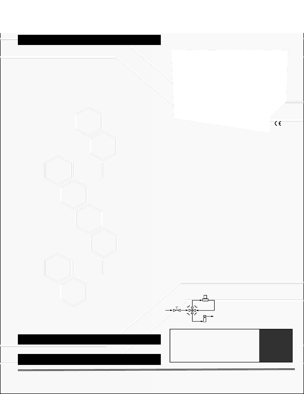
Inlet - regulate to 5-30 psig to deliver 2 SCFH flow;
vent - atmospheric
Universal 100-240 VAC; option heater system (specify
110 or 220 VAC)
1-5V; Optional (1) 4-20mA non-isolated OR (2) relay
contacts w/ 4-20mA or 1-5V
Stainless steel wetted parts consisting of flow control and
sample/bypass valves, flow indicator
GPR-12-333 for non-acid (CO2) gas streams
XLT-12-333 for gas mixture with > 0.5% CO2
5ºC to 45ºC (GPR sensor), -10°C to 45°C (XLT)
GPR-1600
PPM Oxygen Analyzer
Advanced Full Featured Process PPM O2 Analyzer
Advanced Sensor Technology
Unmatched Performance in PPM O2 Analysis
Unmatched Expected Life & Warranty
Unmatched Recovery to 10 PPM
Sensitivity < 0.5% FS Range
Excellent Compatibility with 0-100% CO2
Bypass Sample System
2 Field Selectable Alarm Setpoints
Auto Ranging or Single Fixed
Options: Temperature Control
Auto-Zero and Auto-Cal
Remote Communication via USB,
RS232, RS485
Integral stainless steel bypass sample system
significantly increases user productivity. The
bypass valve isolates the sensor from high
oxygen levels when changing sample lines.
Warranty: 12 months analyzer; 12 months sensor
Optional Equipment
ISO 9001:2008 Certified
19” rack, wall mounting, auto zero/cal, remote communication-contact factory
* Specification subject to change without notice.
2855 Metropolitan Place, Pomona, CA 91767 USA ♦ Tel: 909-392-6900, Fax: 909-392-3665, www.aii1.com, e-mail: info@aii1.com Rev 10/15
INTERTEK Certificate No. 485
Page 2
GPR-1600 W
GPR-1600 W306
The sensor is the heart of any analyzer . . . which means sensor technology is the
critical factor in analyzer performance . . . don’t settle, get the best !
Sensor Housing
Constructed from stainless steel as are
all wetted parts, this unique design
features a compression type o-ring
seal that virtually eliminate air leaks.
An APIMS mass spectrometer verified
that the Bypass Sample System including this housing is capable of
accurately and repeatedly distinguishing hourly changes of 1 ppb oxygen
concentration.
Advancements:
Signal output 2x higher
Innovative design, materials
Bypass Sample System
Integral stainless steel bypass sample
system significantly increases user
productivity. The bypass isolates the
sensor from high oxygen levels when
2855 Metropolitan Place, Pomona, CA 91767 USA ♦ Tel: 909-392-6900, Fax: 909-392-3665, www.aii1.com, e-mail: info@aii1.com Rev 10/15
changing sample lines.
Proprietary mfg process
Insensitive to vibration
Retain compact design
Low cost of ownership
Performance:
Accuracy < + 1% FS
Sensitivity 0.5% FS (50 ppb)
Service life 24 mos < 100 ppm
Recovery air to 10 ppm < 1 hr.
Op temp -20⁰C in 0-100% CO2
No sensor maintenance
Galvanic PPM
Oxygen Sensor
Page 3

Advanced Instruments Inc.
GPR-1600
PPM Oxygen Analyzer
Owner’s Manual
Revised October 2013
2855 Metropolitan Place, Pomona, California 91767 USA ♦ Tel: 909-392-6900, Fax: 909-392-3665, e-mail:
info@aii1.com
Page 4

Table of Contents
Introduction 1
Quality Control Certification 2
Safety & Installation 3
Features & Specificat io n s 4
Operation 5
Maintenance 6
Spare Parts 7
Troubleshooting 8
Warranty 9
Advanced Instruments Inc.
Material Safety Data Sheets 10
2
Page 5

Advanced Instruments Inc.
1. Introduction
Your new oxygen analyzer is a precision piece of equipment designed to give you years of use in a variety of
industrial oxygen applications.
This analyzer is d esigned to measur e oxygen concentrati on in inert gases, gaseous hydroc arbons, hydrogen, an d a
variety of gas mixt ures. In order t o derive maximum perf ormance f rom your new oxygen an alyzer, ple ase read an d
follow the guidelines provided in this Owner’s Manual.
The serial number o f th i s an alyzer may be fou n d o n t h e inside the analyzer. You sho u l d note the serial n u m ber in the
space provided and r etain this Owner’s Manual as a permanent record of your purchase, for future reference and for
warranty considerations.
Serial Number: _______________________
Every effort has been made to select the most reliable state of the art materials and components designed for
superior perfor mance and minim al cost of ownersh ip. This analyz er was tested tho roughly by the manufacturer for
best performan ce. However, modern el ectronic devices do require ser vice from time to ti me. The warran ty include d
herein plus a s taf f o f t r a i n ed professional technicians to quickly ser vi c e your analyzer is your assurance that w e stand
behind every analyzer sold.
Advanced Instruments Inc. appreciates your business and pledge to make effort to maintain the highest possible
quality standards with respect to product design, manufacturing and service.
3
Page 6

Advanced Instruments Inc.
Customer: Order No.:
Model:
GPR-1600 PPM Oxygen Analyzer S/N _____________________
( ) XLT-12-333 PPM Oxygen Sen so r S/N _____________________
TOOL-1001 5/16” Combination Wrench
Configuration:
Ranges: 0-10 PPM, 0-100 PPM, 0-1000 PPM, 0-1%, 0-25%
( ) A-1174-10 PCB Power Supply / Interconnect, 5x Relay Contacts Range ID
( ) Sample, span, zero inlet solenoid valves
( X ) Temperature controlled heater system 85°F specify: ( ) 110VAC (X ) 220VAC
Power: 100/120/220/250 VAC (universal without temperature controlled heater systems)
( ) GPR-1600-W306 option general purpose panel mount 18.2x16x10”
Test
System start-up diagnostics satisfactory
Auto/manual range
Alarm relays activate/deactivate with changes in O2 concentration
Alarm bypass
Analog outputs: Signal output 4-20mA
Range ID: ( X ) 1-5 VDC or ( ) 5x relay contacts plus 1x common
Recovery from air to < 10 PPM in < 60 minutes
Baseline drift on zero gas < ± 2% FS over 24 hour period
Noise level < ± 1.0% FS
Span calibration gas value
Span adjustment within 10-50% FS
Peak to peak over/under shoot < 0.5% FS
Overall inspection for physic a l def ec t s
Options
Notes
2. Quality Control Certification
Date:
Pass
Sensor: ( ) GPR-12-333 PPM Oxygen Sensor
Accessories: Owner’s Manual
CABL-1008 Power Cord
( ) Stainless steel sensor housing, manual flow control and bypass valves, ¼” compression
Enclosure: ( X ) Std. panel mount (“T”) 7.5x10.8x12”; ( ) “TO” option 7.75x 7.75x12”
A-1146-10 PCB Assembly Main / Display Software V. ______
( X ) A-1146-10 PCB Power Supply / Interconnect, 1-5V Range ID
type fittings for sample inlet and vent
( ) Delete sample/bypass valve from above (T and TO options)
( ) Bezel for 19” rack mount 19x12x12” option
( ) GPR-1600-W option general purpose wall mount 12x12x8”
4
Page 7

Advanced Instruments Inc.
Standard:
Manufacturing Procedure No. P-1057 Rev-1,
Published 1/1/1996 and related publications
Mfg. Item No.:
GPR-1600 Series
Description:
ppm Oxygen Analyzer
Serial No.:
___________________________
Customer:
___________________________
Purchase Order:
___________________________
Quantity:
1 of
Warranty Date:
12 months from ______________
Date:
______________
Place:
Pomona, CA
By print name:
Signature:
Title:
The certificate applies to the an al yzer specificall y o r d er ed to use componen t s f o r o xy gen s ervice. Check the QC of the
analyzer to ensure whether such an option was ordered.
Certificate of Cleaning
Oxygen Service
Compressed Gas Association,
Publication: G-4.1 Edition 4,
Title: Cleaning Equipment for Oxygen Service,
The undersigned war rants on behalf of Manufacturer that the product identified
above conforms t o the man ufactu ring, t esting and p ackagi ng crit eria set fo rth by
the ‘Standard’ specified above.
5
Page 8

Advanced Instruments Inc.
Directives:
2006/95/EC Low Voltage
2004/108/EC Electromagnetic Compatibility
Standards:
EN 61010-1 Safety
EN 61326-1 Minimum Immunity Test
ISO 9001:2008
Compliance:
All applicable standards
Products:
General purpose online oxygen analyzers:
GPR-1600UHP series
GPR-1600MS series GPR-16MS series
GPR-1600 series GPR-16 series
GPR-1900 series GPR-19 series
GPR-2600 series GPR-26 series
GPR-2900 series GPR-29 series
GPR-3100 series GPR-31 series
GPR-1500 series GPR-15 series
GPR-2500 series GPR-25 series
GPR-1500AIS GPR-15A series
GPR-1800AIS GPR-18MS/18/28
GPR-2500AIS GPR-980 series
GPR-2800AIS GPR-35
General purpose portable oxygen analyzers:
GPR-1200MS series GPR-12MS series
GPR-1200 series GPR-12 series
GPR-1100 series GPR-11 series
GPR-1000
GPR-2000 series GPR-20 series
GPR-3000 series GPR-30 series
GPR-3500MO GPR-35MO
Intended Use:
Analyze oxygen concentration in a gas mixture in a non-explosive atmosphere.
Manufacturer:
Analytical Industries, Inc. dba Advanced Instruments, Inc.,.
2855 Metropolitan Place
Pomona, California 91767 USA
Tel: 909-392-6900, Fax: 909-392-3665
e-mail: info@aii1.com
Date:
September 15, 2013
Place:
Pomona, California 91767 USA
We hereby declare the above product meets the provisions of the directives and
Patrick Prindible
Vice President & QA Manager
Declaration of Conformity
standards specified. All supporting documents are retained on the premises of the
manufacturer and the notified body above.
6
Page 9

Advanced Instruments Inc.
3. Safety Guidelines
Safety
This section summ arizes t he basic precaut ions a pplica ble to all analy zers. Addition al prec aut ions spec ific to individu al
analyzer are contained in the following sections of this manual. To operate the analyzer safely and obtain maximum
performance follow the basic guidelines outlined in this Owner’s Manua l .
Caution: This symbol is used throughout the Owner’s Manual to CAUTION and alert the user to
recommended safety and/or operating guidelines.
Danger: This symbol is used throughout the Owner’s Manual to identify sources of immediate
DANGER
Read Instructions: Before operating the analyzer read the instructions.
Retain Instructions: The safety precautions and operating instructions found in the Owner’s Manual should be
retained for future reference.
Heed Warnings Follow Instructions: Follow all warnings on the analyzer, accessories (if any) and in this Owner’s
Manual. Observ e all precaut ion s and o peratin g ins truc tion s. Failur e to do so m ay r esult i n perso nal i njury or d amage
to the analyzer.
Heat: Situate and store the analyzer away from sources of heat.
Liquid and Object Entry: The analyz er should n ot be imm ersed in any liqu id. Care sh ould be taken so that liqui ds
are not spilled into and objects do not fall into the inside of the analyzer.
Handling: Do not use f or ce wh en usi ng th e sw itc he s an d kn obs. Bef or e movi n g your an alyz er be su re to di sc onn ect
the wiring/power cord and any cables connected to the output terminals located on the analyzer.
such as the presence of hazardous voltages.
Maintenance
Serviceability: Except for repl acing the oxygen senso r, there are no part s inside the analyz er for the operator to
service.
Only trained personnel with the authorization of their supervisor should conduct mai nt e na nce.
Oxygen Sensor: DO NOT open the sensor. The sensor c ontains a c orrosiv e liquid electrol yte that could be harmful
if touched or ingeste d, refer to the Material Saf ety Data Sheet c ontained in th is Owner’s Man ual. Avoid co ntact with
any liquid or cr ystal typ e pow der in o r arou nd the sensor o r senso r hou sing, a s eith er cou ld be a fo rm of electrolyte.
Leaking sensors should be disposed of in accordance with local regulations.
Troubleshooting: Consult th e gui delin es in sectio n 8 fo r a dvice on the c ommo n oper atin g error s befo re c onc luding
that your analyzer is faulty. Do not attempt to service the analyzer b eyond those means described in this Owner ’s
Manual.
Do not attempt to make r epair s by yourse lf as th is will vo id th e warran ty, as det ailed by s ect ion 9, an d may result in
electrical shock, injury or damage. All other servicing should be referred to qualified service personnel.
Cleaning: T he analyzer sho uld be cleane d only as reco mmended b y the manufact urer. Wi pe off dust and di rt from
the outside of the unit with a soft damp cloth then dry immediately. Do not use solvents or chemicals.
Nonuse Periods: Disconnect the power when the analyzer is left unused for a long period of time.
7
Page 10

Advanced Instruments Inc.
Installation
Gas Sample Stream: En sure the gas stream co mposition of the application is c onsistent with the specificatio ns of
the analyzer/sen sor and review the application co nditions before initiating the installation. Con sult f actory to ensure
the sample is suitable for analysis.
Contaminant Gases: A gas scrubber and flo w indicat or wit h integral metering v alve ar e require d upstrea m of the
of the analyzer to remove interfering gases such as oxides of sulfur and nitrogen or hydrogen sulfide that can
produce false re adings, reduce th e expected life of the sensor and void sensor warran ty if not identifie d at time of
order placement. Consult factory for recommendations concerning the proper selection and installation of
scrubber/filter components.
Expected Sensor Life
With reference to the publish specificat ion located as the last p age of this manual, the exp ected life of all oxygen
sensors is pred icated on the basis of oxygen concentration (< 10,000 PPM), tempera ture (7 7°F/25°C) an d pressure
(1 atmosphere) in “normal” applications. As a rule of thumb senso r life is inversely prop ortional to changes in the
parameters. Deviations of the gas concentration and or temperature outside of the spec i f ications will af f ec t t he life of
the sensor. Avo id exposure to oxygen l evels above 1% (10,000 PPM) for hours at a time.
Failure to do so may result in damage to the sensor(s) as follows:
GPR Series PPM sensors – red uc ed sen sor l ife an d loss o f lo w end sen siti vi ty wh en exposed con tinu ou sly to
20.9% oxygen; sensor will last approximately 6-8 months and may develop a low end offset > 1-2 PPM
XLT Series PPM sensors - reduced sensor life and loss of low end sensitivity (XLT sensor exposed
continuously to the 20.9% O2 content of air will last approximately 7 days).
Accuracy & Calibration
Refer to section 5 Operation. The 0-25% Range is provided only for the purpose of air calibration which is
recommended on ly if span gas is not available. Br inging the analyzer bac k online after calibrat ion with the 20.9%
oxygen content of air, takes longer than calibrating the analyzer with a span gas, for example, 80 PPM oxygen.
Materials
Assemble the necessary zero, sample and span gases and optional components such as valves, coalescing or
particulate fil ters, and pum ps as dictated by th e application; stainless steel tubing is essen tial for maintaining the
integrity of the gas stream for PPM measurements.
Operating Temperature
The sample must be suffici ently coo led before i t enters th e analyzer and any opt ional co mponents. A c oiled 10 fo ot
length of ¼” stainless steel tubing is sufficient for cooling sample gases as high as 1,800ºF to ambient. The
maximum recommended operating temperatu re is 45º C. On an intermittent basis, unless the user is willin g t o accept
a reduction in exp ected sensor lif e – refer to analyz er specification , the analyzer may be o perated at 50 degr ee
temperatures above 25
temperature. As an example, if the analyzer is continuously operated at 35oC, the expected sensor life will be
reduced by ~25%.
Pressure and Flow
All electrochem ical oxygen senso r s respond to partial pressure changes in o xygen. The senso rs ar e equally capable o f
analyzing the oxyg en cont ent of a flo wing sample ga s stream o r monito ring the ox ygen concent ration in am bient air
(such as in a confined space in a control room or an open area such as a landfill or bio-pond).
Sample systems an d flo win g gas s ampl es are g ener ally r equ ir ed fo r appl icat ion s in vol ving o xy gen m easu remen t s in a
gas mixture. Fo r sub PPM measur ements, the use of stainless steel tubing and fittin gs is critica l to maintaining th e
integrity of the gas stream to be sampled. Further, the inlet sample pressure must always be higher than the
pressure at the outlet vent, which is normally at atmospheric pressure.
To analyze a gas stre am, th e gas must flow or be dr awn th rough t he senso r hou sing. The internal sampl e syst em of
the analyzer may include sam ple/bypass valves, shut off valve, a flow control (please che ck the QC sheet to ensure
o
C, the user can expect a reduction in sensor life of ~ 2.5% per degree increase in
o
C. At
8
Page 11

Advanced Instruments Inc.
the included s ample system) , a f low in dicato r and a st ainle ss st eel s ensor h ousin g with an o -ring seal to pr even t the
leakage of air int o the sensor housin g.
Inlet Pressure
Analyzers design ed for flowing samples under positive pressure or for samples at atm ospheric or slightly ne gative
atmospheres, are equi pped with bulkhead tube fitting co nnections at the rear of the analyzer. T he recommended
operating sample pressure is between 5-30 PSIG.
A pressure great er than 30 PS IG may preven t the solen oid valve s from opera ting proper ly (GPR-1600-AV
only). Further, the pres sure of Sample, Sp an and Zero gas must be within 10 PSIG for ease of control of
gas flow rate.
Outlet Pressure
In positive sample pressure applic ations, the sam ple must be vented to ambient air or in a vent with pressure les s
than the sample inlet pressure. If the sample is vented to a line at pressure above ambient, a back pressure
regulated set at no greater 1-2 PSIG must be installed on the downstream of the sensor to ensure a constant
pressure on the sensor.
Flow Rate
Flow rates of 1-5 SCFH caus e no appreci able ch ange in the o xygen rea ding. Howev er, f low rates a bove 5 SCFH may
generate a backpressure on the sensor and cause erroneous oxygen readings.
The analyzer is equ ipped wi th a flo w cont rol valve with a flow indicato r upstream of the sen sor housing. A flow rate
of 2 SCFH or 1 liter per minute is recommended for optimum performance.
Caution
Do not place your finger over the vent ( it pressurizes th e sensor) to test the f low indicator when gas is
flowing to the senso r. R emovi ng your fing er (th e restr ictio n) gen erat es a vac uum o n the senso r and m ay
damage the sensor (voiding the sensor warranty).
Recommendations to avoid erroneous oxygen readings and damaging the sensor:
Do not place your finger over the vent (it pressurizes the sensor) to test the flow indicator when gas is flowing to
the sensor. Removing your finger (the restriction) generates a vacuum on the sensor and may damage the
sensor.
Assure there are no restrictions in the sample or vent lines.
Avoid excessive flow rate, flow rate above 5 SCFH may generate backpressure on the sensor.
Avoid sudden releases of backpressure that can severely damage the sensor.
Avoid the co llection of liqu ids or particul ates on the sensor, they block the di ffusion of oxygen into the senso r -
wipe away any liquid and particulate with a damped cloth only.
Moisture & Particulates
Installation of a suitable coalescing and or particulate filter is required to remove liquid condensates, and/or
particulates fro m the sample gas to prevent clo gging of the sampling system . Moisture and/or particulat es do not
necessarily dam age the sensor itself but collection of moisture/ partic ulat e on the sensin g sur face c an bloc k or inh ibit
the diffusion of sam ple gas into th e sen so r thus re su lt i n g in a redu ction of sensor signal output – an d t h e appearance
of a sensor failu re. Consult factory for recommendations concern ing the proper selection of coalescing/particulate
filters.
Moisture and/or particulates collect ed at the sensor may be removed by either blowing on the sensing su rface or
gently wiping the sensing surface with damp cloth.
Caution: Minim ize the e xposure o f sensor t o air dur ing thi s cleanin g process. Air c alibrat ion follo wed by
purging with zero or a ga s with a lo w PPM oxygen c oncent ration is r ecommen ded follo wing th e cleaning
process.
Mounting
The standard analyzer is ap proved for indoor use only. Outdoor use requi res optional enclosures, c onsult factory.
Mount analyzer as recommended in this manual.
9
Page 12

Advanced Instruments Inc.
The analyzer is configured for panel mounting and requires a 7.5x10.8” (T configuration) cutout with 4 holes for the
analyzer’s front panel. Optional configurations include a panel mount (TO configuration) with 7.75x7.75” cutout; 19”
bezel for rack mounting either the T or TO; 12x12x8” wall mount enclosure (GPR-1600W) and 18.2x16x10” panel
mount configuration (GPR-1600W-306).
Gas Connections
Sample Inlet an d Sample Vent gas lines for PPM analysis r equire 1/8” or ¼ ” stainless steel compr essi o n f ittings; hard
plastic tubing with a low gas permeability factor may be used for measurements of oxygen above 1000 PPM.
Power
Supply power t o the analyzer on ly as rated by the specific ation or markings on th e analyzer enclosure.
The wiring that connects the analyzer to the power source should be installed in accordance with
recognized elec trical standard s. Ensure that the analyzer enclosure is properly grounded and meet s the
requirements of recommended local electrical standards.
Never yank wiring to remove it from a terminal connection.
AC powered analyzers consume a maximum of 30 watts, without the optional heaters. With optional
110 VAC or 220 VAC heaters installed, the maximum power consumption is 230 watts.
10
Page 13

Advanced Instruments Inc.
4. Features & Specifications
11
Page 14

Advanced Instruments Inc.
5. Operation
5.1 Principle of Operation
The GPR-1600 Oxygen Analy zers incorpor ates a variety of PPM range advanc ed galvanic f uel cell type senso rs. The
analyzer is configured for panel mounting and requires a 7.5x10.8” (T configuration) cutout with 4 holes for the
analyzer’s front panel. Optional configurations include a panel mount (TO configuration) 7.75x7.75” with cutout; 19”
bezel for rack mounting either the T or TO; 12x12x8” wall mount enclosure (GPR-1600W); 18.2x16x10” panel mount
configuration (GPR-1600W-306) using the wall mount enclosure. Contact the factory for additional information on
options. All configurations are tested and calibrated by the manufacturer prior to shipment.
The GPR-1600 series analyzers and sensors conform to CE standards and are manufactured under a Quality
Assurance System, certified by an independent agency, in accordance with ISO 9001:2004 standards.
Advance Galvanic Sensor Technology
All galvanic sen sors fu nction on the sam e principl e and ar e specific to oxygen. The y measu re the parti al pre ssure of
oxygen ranging from low PPM to 100 % levels in inert gases, gas eous hydr ocarbons, helium , hydrogen, mixed gases
and acid gas st reams. Oxygen, the fuel for this electrochemical transducer, diffuses into the sensor and
reacts chemically at the sensing electrode to produce an electrical current output proportional to the
oxygen concentration in the gas phase. The sensor’s signal output is linear over all measuring ranges and
remains virtually constant over its useful life. The sensor req u ir es n o m ain t en an ce and is easily an d safely replaced at
the end of its useful life.
Proprietary adv ancements in the design and ch emistry add signif icant advantages t o an extremely v ersatile oxygen
sensing technology. Sensors for low PPM analysis rec over fr om air to PPM levels in minu tes, exhi bit longer life, offer
extended operating range of -20°C to 50°C, have excellent compatibility with CO
sensors) and reliable quality thus giving the user a significant advantage over other competitors. Other
advancements inc lude extendi ng the expec ted life of o ur new generation o f percentage r ange sensor s to five to ten
years with fast er response times and gr eater stability. Another si gnificant development involves the first galvanic
oxygen sensor cap able of measuring o xygen purity co ntinuously and expanded operating temperature r ange from 40°C to 50°C. Consult factory for selection of sensors for your specific applications.
and acid gases (XLT series
2
12
Page 15

Advanced Instruments Inc.
5.2 Electronics
The signal generated by the sensor is processed by state of the art low powered micro-processor based digital
circuitry. T he first st age amplif ies and converts the electrical c urrent into voltage signal. The seco nd stage el imin ates
the low frequenc y noise. The third stag e employs a high frequency f ilter and compensates f or the sensor’s signal
output variations caused by ambient tem perature variat io ns. The result is a very stable sensor signal.
Sensor’s response time of 90 % o f a “step change” is less tha n 10 -30 seconds (actu al experience ma y var y due to the
integrity of sam ple line connecti ons, dead volume and flo w rate selected) o n all ranges under am bient monitoring
conditions. Sensitivity is typically 0.5% of full scale of the lowest range of analysis.
Additional features of the micro-processor based electro nics inc lude manual or au to ranging, auto-zero and auto -cal,
isolated 4-20mA sign al fo r sig nal out put, optional 4-20 mA as range ID, separ at e rel ay co ntac ts rat ed 3 0 VDC m ax @
1A or 110/220 VAC @ 5A are provided for the alarm feature. Optional range ID contacts are rated at 30 VDC @1A.
Whenever the analy zer is span c alibrated, a uniqu e algorithm predicts and displays a message indicatin g a ‘weak
sensor’ (if the sensor output has fallen below a certain level), suggesting the sensor be replaced in the near future.
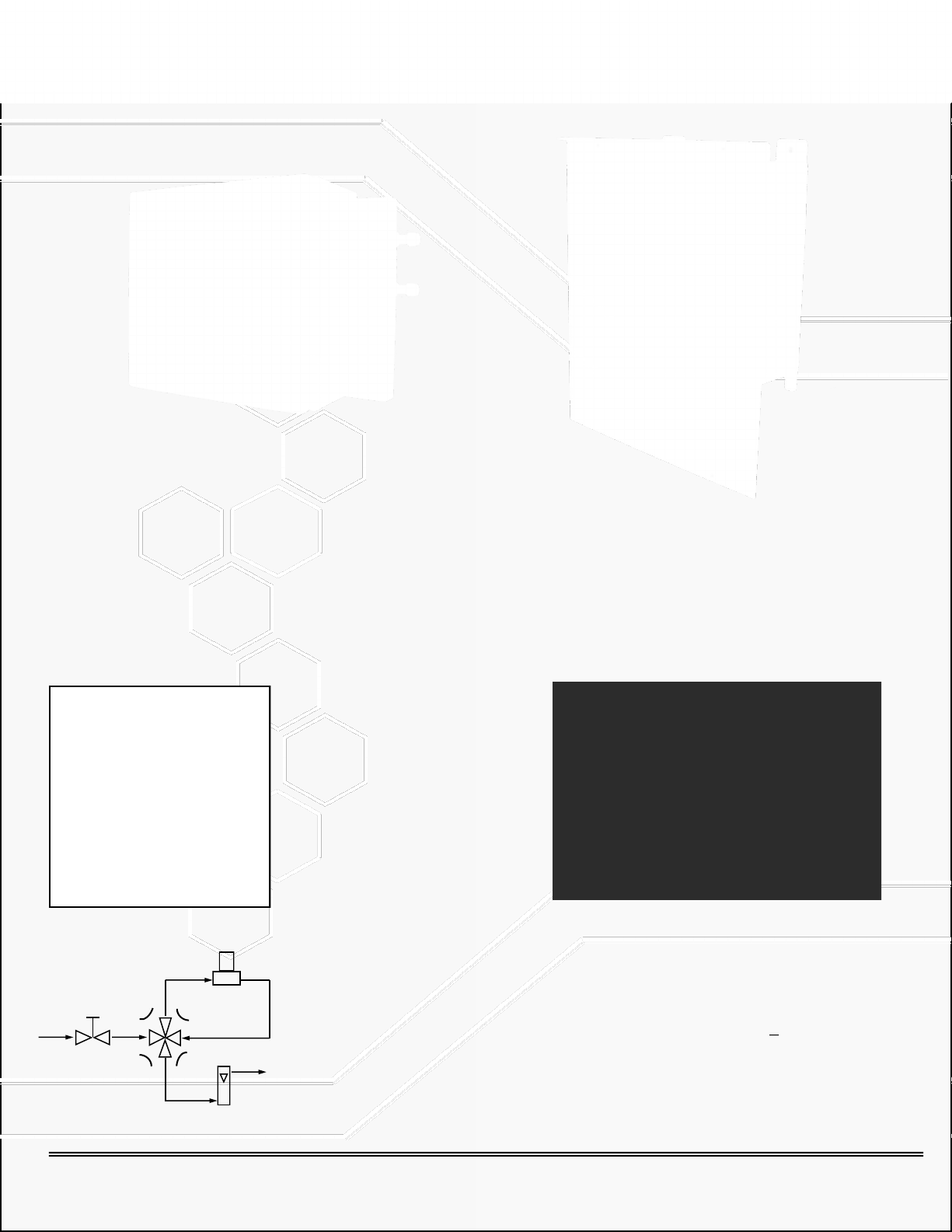
5.3 Sample System
For accurate measu rements, the sam ple gas must be prop erly presented t o the sensor. In stan dard form, the GPR1600 is equipped with a sample system that complements the performance capabilities of the advanced oxygen
sensor.
The integral sam ple syst em of the anal yzer is shown sc hematicall y below ( please ch eck the QC sheet in th is manual
to ensure the analyzer is equipped with the sample system ordered).
Advanced Instrum ents Inc. offers a full l ine of sample ha ndling, c onditioni ng and experti se to meet your application
requirements. Contact us at 909-392-6900 or e-mail us at
info@aii1.com for your specific requirements.
13
Page 16
Advanced Instruments Inc.
5.4 Accuracy Overview
Single Point Calibration: As previously described
the galvanic oxygen sensor generates an electrical
current proportional to the oxygen concentration in
the sample gas. I n the ab senc e of ox ygen the senso r
exhibits an absolute zero, e.g. the sensor does not
generate a cu rrent output in the absen ce of oxygen.
Given the linearity and absolute zero properties,
single point calibration is possible.
Pressure: Because sensors are sensitive to the
partial pressure of oxygen in the sample gas, their
output is a function of the number of molecules of
oxygen 'per unit volume'. For best accuracy, the
pressure of the sam pl e g as and that of the calibration
gas must be the same (in reality within 2-5 psi) so
that when the SAM PLE/S PAN gas es are switc hed, th e
gas flow rate would not drastically change.
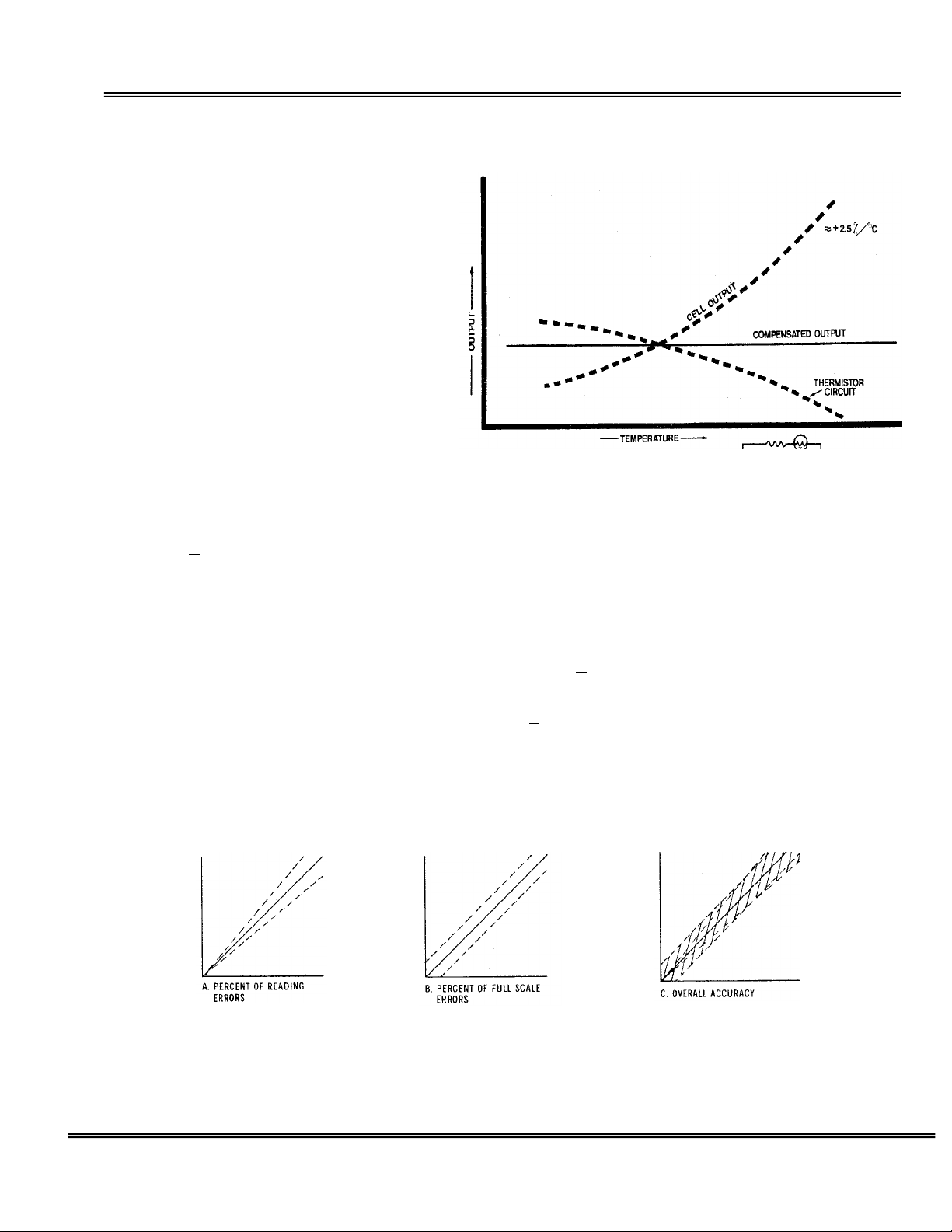
Temperature: The rate at which oxygen molecules diffuse into th e sensor is controlled by a T eflon membrane
otherwise known as an 'oxygen diffusion limiting barrier. The fact that all diffusion processes are temperature
sensitive, the senso r's electrical o utput also varie s with temper ature. This var iation is relat ively constant (2.5% per
ºC chan ge in temperature). A tem perature compensation c ircuit employing a thermistor offsets this effect with an
accuracy of +
that is virtually independent of small ambient temperature variation. To mini mize error in oxygen m easurement , the
calibration of th e analyzer shou ld be carried out as c lose as possible to t he temperature dur ing sampling. A small
temperature variation of ~10º F will produce < 2% error.
Accuracy:
1) 'Percent of reading errors', illustrated by Graph A below, such as +
compensation circuit due to the tolerances of the resistors and thermistor.
2) 'Percent of full scale errors', illustrated by Graph B, such as +
tolerances in th e electro nic compon ents, which are r eally mini mal due to tod ay's technology and the fact that other
errors are 'spanned out' during calibration.
Graph C illustrat es these 'w orse case' s pecificatio ns that are ty pically use d to develo p an analyzer's overall accuracy
statement of < 1% of full scale at constant temperature or < 5% o ver the operati ng tem perature range. QC testing
is typically < 1% prior to shipment.
Example 1: As illustrat ed by Graph A any error dur ing a span adju stment, e.g., at 20.9% (air) of full scale range
would be multipl ied b y a f ac tor of 4.78 (100/20.9) when used for measurem ent s of 95-100 % oxygen concentrations.
Conversely, an error during span adjustment at 100% of full scale range will be reduced proportionately for
measurements of lower oxygen concentrations. Refer to the Calibration section for additional details.
5% or better (over th e operating temper ature range of th e analyzer) and generates an o utput signal
In light of the above parameters, the overall accuracy of an analyzer is affected by two factors:
5% inherited error in the temperature
1-2% linearity errors generally associated with
14
Page 17

Advanced Instruments Inc.
Four mounting holes on four corners to secure
5.5 Mounting the Analyzer
The standard GPR-1600 is designed to be panel mounted and requires a cutout that accommodat es the enclosure
and 4 mounting bolts. The design also lends itself to 19” rack mounting with an optional bezel or wall mount
enclosures as illustrated below.
5.5.1 Procedure
1. The standard GPR-1600 is designe d for panel mounting dir ectly to any flat vertic al surface, wall or bu lkhead
plate with the appropriate c ut out and four ¼” diameter holes for in sertion of the mounting studs through the
front mounting bazel.
2. When mounting the analyzer, position it approximately 5 feet above the floor for better viewin g purposes and
easy access to various functions of the analyzer. Leave suff icient room for ac cess to t he t ermina l con nectio ns at
the rear of the enclosure.
3. Note: The pr oximity of t he analyzer t o the sampl e point and use of optional sample con ditioning com ponents,
such as a sample coo ling coil, a coalesci ng filter and or a parti culate filter may h ave an impact on sam ple lag
time and hence the analyzer response time.
analyzer on a flat vertical surface
15
Page 18

Advanced Instruments Inc.
Rear of analyzer showing the SAMPLE, SPAN, ZERO AND
Flow Control Valve
5.5.2 Gas Connections
The GPR-1600 with its standar d flo w thr ough co nfigur ation is desi gned fo r positi ve sample pressure and requi res ¼”
compression type connections for incoming sample, span and zero gas and outgoing vent lines.
The user is responsible for providing calibration gases and other optional components (if not purchased with the
analyzer).
Caution: The sample, span and zero gas pressu re must be set between 5-30 PSIG and must be within 5 PSIG of
each gas. Failure t o do so w ill cause a su dden spike
in the gas flow when switching from sample to
span/zero gas and back which may cause an
upward/downward spike on the analyzer signal
output.
Flow Control Valve: A flow control valve is
mounted upstream of the sensor and provides
means of controlling the flow rate of the sample,
span and zero gase s. Sample flow rate of 1-5 SCFH
cause no appreciabl e change i n the oxygen reading.
However, for optimum performance, a flow rate of
1-2 SCFH is recommended.
Caution: Do not place your finger over the fitting
designated as t he vent (it pr essu rizes the sen sor) to
test the gas flow. Blocking of the gas vent will
pressurize the sensor and by suddenly removing
finger, a slight vacuum will b e pulled on the senso r
which may damage the sensor.
VENT ports (Span and Zero ports are optional)
16
Page 19

Advanced Instruments Inc.
5.5.3 Procedure
1. Caution: Do not change any of the factory’s setting until instructed.
2. Regulate the sample gas pressure and sample flow as described in the section “Pressure & Flow” above.
3. Install the “Sample Vent” line connection to the fitting labeled SAMPLE VENT.
4. Install th e incoming sample, span and zero gas line to the fitting labeled SAM PLE, SPAN and ZERO (Span and
Zero ports are optional, check the QC certificate for the options included with your analyzer).
5. Set the flow rate to 1-2 SCFH.
6. Keep the Sample/Bypass Valve at Bypass position.
7. Allow gas to flow through the analyzer for 3-5 minutes before proceeding for installation of sensor (the analyzer
is generally shipped with the sensor installed but if the sensor is included in a separate sealed bag, follow
instructions to install the sensor Section 5.7).
5.6 Electrical Connections
Incoming power for the 100-250V AC powered analyzers is supplied through a universal power entry module. A
standard computer type power cord (Part# A-1008) is required for the universal power entry module. A well
grounded insulated power cable is recommended to avoid noise resulting from unwanted interference.
The appropriate AC po wer su pply (1 10V o r 220V) m ust speci fied be sp ecified at order plac ement if t he analy zer is to
be equipped with a temperature controlled heater system.
Power consumption is approximately 30 watts without optional heater and 150-200 watts with the heater system.
Caution: Integral 4-20mA co nverters ar e inter n ally pow ere d and do not require exter na l po wer . DO NOT sup ply any
voltage to any of the terminals of the 4-20 mA signal output or the 4-20 mA range ID. If a power is suppli ed, th e 420 mA chip can be permanently damaged.
17
Page 20

Advanced Instruments Inc.
Power input terminal
Signal and alarm output terminals
Sensor Housing
Optional Range ID
The standard 1-5 VDC output i s provided for range identification, as describe d below. An optional 4-20 mA signal or
5 independent rela y contact represent ing 5 ranges a my be provided as well. Check the QC certificate to verify the
option(s). The appropriate relay contac t will close when a spec ific range is selec ted. The dry c ontacts are rated at
30VDC @ 1A.
The voltage or 4-20 mA Range ID; Range 1= 5V or 20 mA
Range 2 = 4V or 16 mA
Range 3 = 3V or 12 mA
Range 4 = 2V or 8 mA
Range 5 = 1V 0r 4 mA
Interior of the GPR-1600 with optional Wall Mount Enclosure
18
Page 21

Advanced Instruments Inc.
5.6.1 Procedure
1. As illustrated above the al arm relays and sign al output connec tions are hard wired t o push-open type t erminal
blocks located at the rear of the analyzer.
2. Use a small bladed scr ewdriver to push the lev er down and insert the stripped end of the wire into the slot.
NOTE: Strip insulation of the wir es no more than 3/16 inch in length.
3. Insert the stripped end of the cables int o the appro priate term inal slots assur ing no bare wire remains ex posed
that could come in contact with the back panel of the analyzer enclosure.
4. Release the lever to secure the wires in the receptacle.
5. To connect to an active relay or “fail saf e”, conn ect the live c able to the c ommon ter minal C an d the seco ndary
cable to the normally open NO terminal.
6. To break the connection upon rela y acti vati on, connect the secondar y cable to the norma ll y close d NC termi na l .
Danger: While connecting th e cables t o the rela y terminal s, ensure th ere is no vo ltage on the cables t o
prevent electric shock and possible damage to the analyzer.
Caution: Assure the st ri pped w ire end s of the c a ble ar e f ull y in sert ed in to the t erm inal slo ts an d do no t
touch each other or the back panel of the analyzer enclosure.
5.6.2 Oxygen Level Alarms
The analyzer is configured with two user a djustable thre shold type alarm r elays that can be configured in the field
from the ALARM option on the MAIN MENU as follows:
Establish independent alarm set points
Either Hi or Lo oxygen condition
Either On or Off (enabled or disabled)
Both alarms may be temporarily defeated using a user entered ‘timeout’ period (normally in minutes)
The alarm set poi nt repr esents an oxygen valu e. When th e oxygen r eading exceeds (high alarm) or falls below (low
alarm) the alarm set point, the relay is activated and the LCD displays the alarm condition.
When activated, the alarm function triggers the corresponding SPDT Form C non-latching relay rated @ 5A, 30VDC or
240VAC resistive. To prevent chattering of the relays, a 2% hyster esis is add ed to the al arm set point. This means
that the alarm wi ll remain active u ntil the oxygen re ading has fallen 2 % below the alarm set point (high alar m) or
risen 2% above the a larm set point ( low alarm) after the alarm was act ivated. The timeout feature is useful while
replacing the ox ygen senso r or du ring cal ibration when the oxygen readin g might w ell rise above th e alarm set point
and trigger a false alarm.
Note: When making connections the user must decide wheth er t o c o n f i gu r e/ connect Alarm 1 an d A larm 2 in failsafe
mode (Normally Open – NO – where the alarm relay de-en ergizes and c loses in an alar m conditio n) or non-failsafe
mode (Normally Closed – NC – where alarm relay energizes and opens in an alarm condition).
5.6.3 Power/System Failure Alarm
A dry contact rat ed at 30VDC @ 1A is provid ed as a pow er/system failur e alarm tha t activ ates when pow er suppl ied
to the analyzer’s circ uits is interr upted. The c ontact is norm ally closed but opens when the power t o the analy zer is
switched off or interrupted. The power fail alarm cannot be disabled.
19
Page 22

Advanced Instruments Inc.
5.6.4 4-20 mA Signal Output
The analyzer provides a 4-20mA full scale signal with a fully isolated ground for external recording devices. The
integral IC on the main PCB provides 4-20mA fu lly iso lated s i gnals for output and optional range I D. This IC does not
require any extern al power. To check the signal output of the 4-20mA E/I integrated circuit connect an ammeter as
the measuring devi ce and confirm the output is within +
Bypass switch t o OFF position). A finer adjustment of the zero offset of the 4-20mA c onverter can be achieved by
using AII Configuration Software via a PC. Consult factory for instr uctions.
0.1mA of 4mA (without sen sor installed or with the sensor
5.6.5 Range ID
The standard range ID is designated with a voltage output corresponding to a specific range. For example, 5V
corresponds to th e least sensitive range ( 25% on the GPR-1600 an alyzer) and drops 1V for each additional range.
Optional 4-20 mA signal as range I D is also available. With 4-20 mA range ID option, 20mA r epresents the least
sensitive range and it drops by 4mA (16mA, 12mA, 8mA, 4mA) fo r each additi onal ran ge. Plea se chec k the QC sheet
to confirm the range ID option ordered.
Relay contacts as sociated wit h each range may a lso be pro vided as rang e ID. With r elay contact s as range ID, the
common pin of all relays i s connected to th e terminal marked COMM and five (5) nor mally open rel ay contacts th at
close when the related range is active. The dry contacts are rated at 30VDC @ 1A.
Caution:
external voltage will permanently damage the 4-20mA converter.
The integr al 4-20mA converters are int ernally powered and do not requir e external power. Applying any
5.6.6 Loss of Flow Alarm
The analyzer may be e quipped with an optional integral lo ss of flow/low flow alarm. The alarm is set at 1.5 SCFH .
The contact w ill close when th e gas flow exceed s 1.5 SCFH but will open when the gas flow falls below 1.5 SCFH.
The set point i s r elatively rou gh, therefore, to prevent fa lse alarm, set t h e gas flow rate above 2 SCFH. Check the QC
certificate to verify whether this option is available with your analyzer.
The contact is rated at 1A@30 VDC. Do not exceed the recommended rating.
5.6.7 Temperature Controlled Heater System with
Thermal Runaway Protection
The standard GPR-1600 Series analyzer is generally not equipped with the
heater system. H owever, in anticipation o f very low PPM (less t han 0.2
PPM) oxygen analysis, the user may elect to add the heat er system. If the
analyzer is equipped with an optional temperature controlled heater
system, open th e f r o n t door of the analyzer to ac c ess it. This un it is a PID
controller w hich operates bet ween 0-99°F. At the factory the controller is
programmed to maintain the temperature at 85°F.
Caution: Do not change th is setting. A higher tem perature
setting may dra stically reduce sensor life and possibly cause
damage to the elec tronic circuitry of both the controller and
the analyzer.
Warning: Keep th e front door securely fastened and closed when the
temperature controller is ON.
20
Page 23

Advanced Instruments Inc.
Nut holding two sections of the
J2 device
When power is a pplied to the temperature c ontroller, the contro ller tunes itself to eliminate and/or minimize the
over/under shoo t of temperature from the set point. It is reco mmended that at initial st art-up, when replacing th e
oxygen sensor or w hen trouble shoot ing, turn off t he power to the heater ( by setting the temp erature set point at
60°F to prevent overheating the analyzer). When operating the analyzer under normal conditions, set the
temperature controller at 85⁰F.
Changing the display value from °F to °C:
1. Push the UP ARROW and ENTER buttons down for 5 seconds to access the SECURE MENU
2. Press INDEX to advance to the F-C MENU
3. Select °C or °F by pressing the UP ARROW key
4. Press the ENTER key when F-C starts flashing on the display
5. Press INDEX to exit the SECURE MENU
Heater Runaway Protection
Part of the opt ional temperature co ntrolled heater system is a heater runaway protection circuit t hat protects the
electronics in t he event the te mperatur e contro ller should f ail and thereb y allowing t he heater to runaway dam aging
the components in side the analyzer.
The runaway protec tion is provided by a J2 t ype device positio ned between the
temperature con troller an d the heat er. Th is device cu ts-off power to the h eater if
the temperature inside the analyzer exceeds 70°C. Sh o u l d th e J2 devi c e cut power
to the heater, c or rect the pro b lem and r es et th e r unaw ay pr ot ecto r devic e (J2 w ill
conduct under normal conditions) by exposing it to 0°C for a few minutes (a
refrigerator freezer will do). NOTE, should the J2 fail to reset itself, replace it.
To access the J2, r emove the back c over of th e analyzer. Th e j2 is moun ted on a
white terminal block as shown in the figure above.
5.7 Installing a new Oxygen Sensor
The analyze r is equipped with an internal oxygen sensor that has been te sted and calibr ated by the manufac turer
prior to shipment an d is fully operatio nal from th e shipping c ontainers. Th e
sensor has been inst alled at the factory. However, it may be necessary to
install the senso r in the field. Caution: Complete “ESTABLISHING POWER
TO ANALYZER” section before proceeding.
Caution: DO NOT open/dissect the sensor. The sensor contains a
corrosive liquid electrolyte that could be harmful if touched or ingested,
refer to the Material Safety Data Sheet contained in the Owner’s Manual
appendix. Avoid c ontact with any liquid o r crystal type pow der in or aro und
the sensor or sensor housing, as either could be a form of electrolyte.
Leaking sensors should be disposed of in manner similar to that of a
common battery in accordance with local regulations.
sensor housing
21
Page 24

Remove two red taps from
sensor PCB before ins t al li ng
You may check the Sen sor ou tput in air, it must
be within ~500 uA to 950 uA
5.7.1 Procedure
1. Do not remove sensor from its original package until the analyzer is ready to accept sensor
installation.
2. Make sure that a low PPM gas is flowing thr o u gh the analyzer.
3. Set the sample flow rate between 1-2 SCFH
4. Loosen the nut at the bottom of the sensor housing with 5/16” ranch provided.
5. Twist the upper section of the sensor housing 90 degree and then pull it away.
6. Remove old sensor (if previously installed).
7. Remove the new sensor from the package (use a pair of scissors to cut the bag, do not use hands to
tear the bag)
8. Remove the two red ribbons from the two ring gold contact plate at the back of the sensor.
Advanced Instruments Inc.
Quick Air Calibration when installing a new sensor
1. Insert the sensor into the upper section of the sensor housing with the contact plate facing toward the
two gold pins of the sensor housing. Hold the sensor and the sensor housing in your hand while
keeping the sensor pushed against the two gold pins.
22
Page 25

Advanced Instruments Inc.
Hold the sensor pre ssed against the
2. Advance the cursor on the MAIN MENU to SAMPLE and press ENTER to accept the selection. Check the
oxygen reading; it should reach close to 20.0% (+7% -4%) indicating that the sensor has proper signal
output. At this time perform a quick air calibration (detailed instruction for span calibration follows).
3. After air calibration, insert the sensor into the bottom section of the sensor housing with metal screen
of the sensor facing down. Place the upper section of the sensor housing, push it gently downward and
twist it 90 degree until it fits on the lower section of the sensor housing. Tighten the nut (3/4 turn after
figure tight) holding the two section of the sensor housing.
contact pins inside the housing
23
Page 26

Advanced Instruments Inc.
5.7.2 Span Gas Preparation
The analyzer must be calibrated periodically; see the Calibration Section below for recommendations.
Required Components
1. Certified span gas cylinder with an oxygen concentration, balance nitrogen, approximating 80% of the full scale
range of analysis or one range above the intended measuring range.
2. Regulator to set gas pressu re to 5-30 psig (for the solenoid valves to operate proper ly, the differen ce between
the Span and Sample gas pressure must not exceed 5 PSIG).
3. Flow meter to set the flow between 1-2 SCFH (only if analyzer is not equipped with integral flow control device).
4. Suitable fittings and 1/8” or ¼” dia. metal tubing to connect the regulator to the flow meter inlet.
5. Suitable fitting and 1/8” or ¼” dia. 4-6 ft. in length of metal tu bing to c on nec t fr om t he fl o w met er ven t to t u be
fitting connection designated SAMPLE IN or SPAN IN (for analyzer with a separat e span po rt) at th e rear of t he
analyzer.
Procedure
1. With the span gas cylinder valve closed, install the regulator on the cylinder.
2. Open the regulator’s exit valve and partially open the pressure regulator’s control knob.
3. Open slightly the cylinder valve.
4. Loosen the nut connecting the regulator to the cylinder and bleed the pressure regulator.
5. Retighten the nut connecting the regulator to the cylinder
6. Adjust the regulator exit valve and slowly bleed the pressure regulator.
7. Open the cylinder valve completely.
8. Set the outlet pressure between 5-30 psig using the pressure regulator’s control knob.
9. Caution: Do not exceed th e recommende d pressure ran ge. Excessive pressure could cau se malfunctioning
of the solenoid valves resu lt in erro n eous readings.
24
Page 27

Advanced Instruments Inc.
System Self Test
Analog
OK
GPR Series Oxygen Analyzer
Standby
85⁰F 100Kpa
12/31/07 12:00:00
5.8 Establishing Power to the Electronics:
Once the power to th e el ec t r o n ics is established, the digital dis pl ay responds instan t an eo usly. When pow er is applied,
the analyzer performs several diagnostic system status checks termed “SYSTEM SELF TEST” as illustrated below:
CPU
Memory
RTC
Software Version X.XX
Advanced Instruments
2855 Metropolitan Place
Pomona, CA 91767
Tel: 909-392-6900
Fax: 909-392-3665
e-mail:
After 3 seconds the system defaults to the STANDBY mode and the LCD displays the following:
info@aii1.com
OK
OK
OK
* MAIN MENU
Sample
Span
Zero
Alarm
System
Standby
Auto Range
25
Page 28

Advanced Instruments Inc.
5.8.1 Menu Format
Menu selected – displayed on the top line in the upper left corner of the display.
Menu options available – all menus displayed on the left side of the LCD.
Menu option selected - indicated by the cursor (*) positioned to the left of the menu option selected.
System mode - indicated at the top center of the display.
Range mode and current auto or fixed manual range - displayed on the first line at the bottom of the display.
Temperature insi de of the analyzer and ambient pressure - displayed on the second line at the bottom of the screen.
Note:
In the event po w er t o t h e an alyzer is inter rupted, the system defaults to the “Standby” mode when power
is restored. To r esume sampling, advance the c ursor (*) to “Sample” mode, press ENTER to selec t and
select the range mode as described below.
5.8.2 Menu Navigation
The four (4) pushbuttons located on the front of the analyzer control the system’s micro-processor:
1. Green - ENTER (select)
2. Yellow UP ARROW – advance cursor up
3. Yellow DOWN ARROW – advance cursor down
4. Red – ESC (menu)
26
Page 29

Advanced Instruments Inc.
Standby
Standby
85⁰F 100Kpa
12/31/2011 12:00:00
Standby
85⁰F 100Kpa
12/31/2011 12:00:00
Select the menu option by advancing cursor (*) by repeatedly pressing the yellow UP/DOWN ARROW keys.
Accept the menu option selected with cursor (*) by pressing the green ENTER key.
Abort the menu option selected with cursor (*) and return to the previous menu by pressing the r ed ESC key.
Note:
If a selection is not made within 30 seconds, the system returns to the MAIN MENU.
5.8.3 Range Mode Selection
Advance the cursor (*) to the “Sample” option as illustrat e d an d pr ess the green ENTER key to accept the selection.
MAIN MENU
* Sample
Span
Zero
Alarm
System
Auto Range
The following menu appears:
* SAMPLE
Auto Range
Manual Range
Bypass
Standby
Auto Range
The analyzer is equipped with five (5) standard measuring ranges (see specification) and provides users with a
choice of sampli ng mod es. By ac cessing t he MAIN M ENU, u sers may s elect eit her the Auto Range or a fixed Manual
Range mode.
Note: During span calibration, the analyzer will automatically switch to Auto Range mode.
5.8.4 Auto Range Sampling
In the Auto Range mode, the analyzer will automatically select the appropr iate full scale range depend ing on the
concentratio n of oxygen in a sampl e gas. The displa y will shift to the n ext higher range when the oxygen readi ng
exceeds 99.9% of the curren t r an ge. T h e display wil l shift to th e next lower range when th e oxygen readin g drops to
85% of the next lower range.
27
Page 30

Advanced Instruments Inc.
Procedure:
From the SAMPLE menu, advance the cursor (*) to the “Auto Range” option and press ENTER:
Standby
85⁰F 100Kpa
12/31/2011 12:00:00
Similarly, the Bypass and Standby modes do not apply to analyzers equipped with manual Sample System
Sample
85⁰F 100Kpa
12/31/2011 12:00:00
For example, if th e analyzer is reading 1 PPM on the 0-10 PPM range an d an u pset occurs, t h e display will shift t o t h e
0-100 PPM range when the oxygen re adin g exc eeds 9.99 PPM. Conver sely, o nc e the u pset co nditi on i s corr ected, the
display will shift back to the 0-10 PPM range when the oxygen reading drops to 8.5 PPM.
SAMPLE
* Auto Range
Manual Range
Bypass
Standby
Auto Range
Note:
Within seconds t he system assesses the oxyg en concentration, selec ts the appropriate range ( as described above)
and returns to the MAIN M ENU in the “Sample” mode. On the secon d line from the bo ttom o f the menu screen, th e
Auto Range mode is indicated along with the current full scale range.
For an optional automated Sampl e System, the syst em displays a messa ge "Opening Sa mple Valve". This
message does not apply to analyzers equipped with standard manually operated Sample System.
* MAIN MENU
Sample
Span
Zero
Alarm
System
Standby
Auto Range
5.00 PPM
0 to 10 PPM
28
Page 31

Advanced Instruments Inc.
Procedure:
From the SAMPLE menu, advance the cursor (*) to the “Manual Range” option and press ENTER:
Sample
85⁰F 100Kpa
12/31/2011 12:00:00
Sample
85⁰F 100Kpa
12/31/2011 12:00:00
5.8.5 Manual Range Sampling
In the manual ran ge m o de, th e disp lay will n ot shif t automa tic ally. Inst ea d, w hen the oxy gen r ead in g exc ee ds 125%
of the upper limi t of the c urr ent r ange, an” OVER RANGE” warning will b e displ aye d. Once the OVER RANGE warning
appears the user must advance the analyzer to the next higher range.
SAMPLE
Auto Range
* Manual Range
Bypass
Standby
Auto Range
The following display appears:
MANUAL RANGE
0 to 25%
0 to 1%
0 to 1000 PPM
0 to 100 PPM
* 0 to 10 PPM
Auto Range
Advance the cursor (*) to the desired fixed manual range, e.g. 0 to 10 PPM and press ENTER.
Within seconds th e syst em a ssess es th e ox ygen c onc ent ration and returns to the M AIN MEN U in th e “Sam ple” mo de.
On the second line at the bottom of the menu, the Manual R ange mode is indic ated along with the fixed full scale
range selected.
29
Page 32

Advanced Instruments Inc.
Sample
85⁰F 100Kpa
12/31/2011 12:00:00
Sample
85⁰F 100Kpa
12/31/2011 12:00:00
* MAIN MENU
Sample
Span
Zero
Alarm
System
Standby
5.00 PPM
Manual Range
If the oxygen reading exceeds 125% of the full scale fixed range manually selected, the system displays the
following message, e.g., on 0-10 PPM range:
* MAIN MENU
Sample
Span
Zero
Alarm
System
Standby
Manual Range
0 to 10 PPM
12.50 PPM
OVER RANGE
0 to 10 PPM
5.8.6 Setting Alarms
The analyzer is c onfigured wit h two user adjust able threshold ty pe alarm relays that can be configured in the field
from the ALARM option on the MAIN MENU as follows:
Establish independent set points
Either Hi or Lo
Either On or Off (enabled or disabled)
Both temporarily defeated using a user entered ‘timeout’ period (normally a few minutes)
The alarm set point repr esents a value. When the oxygen rea din g ex c eeds (high alarm) o r f all s b el o w ( l o w alarm) the
alarm set point, the relay is activated and the LCD displays the alarm condition.
When activated the alarms tri gger SPDT Form C non-latchi ng relays @ 5A, 30V DC or 240VAC resistive. To pr event
chattering of th e r elays, a 2% hysteresis is ad ded to the alarm set po i n t. T h i s m ean s th at th e al ar m w il l r em ain active
until the oxygen readi ng ha s f allen 2% below th e alar m s et po int (hi gh alar m) o r ris en 2 % above th e al arm set po int
(low alarm) after the alar m w as act ivated. T he tim eout f eatu re is usef ul w hile r eplac ing t he oxyg en sen sor or durin g
calibration when the oxygen reading might well rise above the alarm set point and trigger a false alarm.
Note: When making connections the user must decide whether to configure/connect Alarm 1 and Alarm 2 in failsafe
mode (Normally Open – NO – where the alarm relay de-en ergizes and c loses in an alar m conditio n) or non-failsafe
mode (Normally Closed – NC – where alarm relay energizes and opens in an alarm condition).
Procedure: Advance the cursor (*) to the “Alarm” option and press the green ENTER key to accept the selection.
30
Page 33

Advanced Instruments Inc.
Sample
85⁰F 100Kpa
12/31/2011 12:00:00
85⁰F 100Kpa 12/31/2011 12:00:00
85⁰F 100Kpa 12/31/2011 12:00:00
MAIN MENU
Sample
Span
Zero
* Alarm
System
Standby
5.00 PPM
Auto Range
The following menu appears:
ALARM Sample
* Set Alarm 1
Set Alarm 2
Alarm 1 HI
Alarm 2 LO
Alarm 1 ON
Alarm 2 OFF
Alarm Timeout
Auto Range 0 to 10 PPM
Advance the curso r ( * ) to the “Set Alarm 1” option and pres s the green ENTER key to accept the selec ti o n. The Menu
will then prompt to select the un its of alarm set points, f or example, % or PPM or PPB (PPB optio n is for GPR-1600UHP analyzer only).
After selecting the gas units, the following menu appears (assuming the user selected PPM units):
Sample
0 PPM
02
Press UP or DOWN
to change value
ENTER to Save
ESC to Return
Set Alarm 1 in PPM
0 to 10 PPM
Auto Range 0 to 10 PPM
Follow selection of set point, press the ENTER key to save the alarm value or ESC to return to the MAIN MENU.
Within a few seconds after pressing the ENTER key, the system returns to the MAIN MENU.
Repeat the above steps for “Set Alarm 2”.
Configure Alarm 1 and Alarm 2 as High or Low by ad vancing the cursor (*) to the desired feature as illustrated
below.
31
Page 34

Advanced Instruments Inc.
85⁰F 100Kpa 12/31/2011 12:00:00
Sample
85⁰F 100Kpa
12/31/2011 12:00:00
85⁰F 100Kpa 12/31/2011 12:00:00
ALARM Sample
Set Alarm 1
Set Alarm 2
* Alarm 1 HI
Alarm 2 LO
Alarm 1 ON
Alarm 2 OFF
Alarm Timeout
Auto Range 0 to 10 PPM
Press the ENTER key to toggle between the settings: HI and LO and/or ON and OFF.
Pressing the ENTER key will toggle the selection and the system will return to the MAIN MENU.
ALARM TIMEOUT: The Alar m Timeout feature allows the user to select a “time del ay” to prevent th e alarm from
triggering rela y immediat ely after the alarm c ondition occu rs. The time d elay featu re allow s the user from tri ggering
a false alarm du ring mainten ance or self induces sign al spike. In order to ent er the time delay, advance the cursor
(*) to the “Alarm” option and press the green ENTER key to accept the selection.
MAIN MENU
Sample
Span
Zero
* Alarm
System
Standby
5.00 PPM
Auto Range
The following menu appears:
ALARM Sample
*Set Alarm 1
Set Alarm 2
Alarm 1 HI
Alarm 2 HI
Alarm 1 ON
Alarm 2 ON
Alarm Timeout
Auto Range 0 to 10 PPM
Advance the cursor (*) to the “Alarm Timeout” option and press the green ENTER key to accept the selection.
The following menu appears:
0 to 10 PPM
32
Page 35

Advanced Instruments Inc.
Alarm Delay in Minutes
85⁰F 100Kpa 12/31/2011 12:00:00
Sample
85⁰F 100Kpa
12/31/2011 12:00:00
Sample
00 MIN
Press UP or DOWN
to change value
ENTER to Save
ESC to Return
Auto Range 0 to 10 PPM
Follow the prom pt above and press the ENTER key to save the alarm timeo ut value or ESC to return to the MAIN
MENU.
Within a few seconds after pressing the ENTER key, the system returns to the MAIN MENU.
5.8.7 System Menu
The analyzer is e quipped with a wide range of features that enables users to enhance performance and tailor their
interface with the analyzer. The SYSTEM menu shown below lists the features available and is followed by a
description of each function. Most of the functions are initi ated by togg ling between options by pre ssing the ENTER
key as previously described.
Advance the cursor (*) to the “Alarm” option and press the green ENTER key to accept the selection.
MAIN MENU
Sample
Span
Zero
Alarm
* System
Standby
Auto Range
The following menu appears:
* SYSTEM
Enable Low Flow Alarm
Disable Alarm During Cal
Signal Average
Range
Logging Interval
Temp Coeffici en t
View Data Graph
Set Clock (and Date)
Logging ON
Show Text
Display Negative (Reading) ON
5.00 PPM
0 to 10 PPM
33
Page 36

Advanced Instruments Inc.
microprocessor).
Disable Alarm During Cal
Press ENTER key to toggle between ENABLE and DISABLE.
off of
seconds when selecting LOW, MEDIUM OR HIGH option
Range
Same as Auto/Manual Range option found on SAMPLE menu.
purposes.
memory.
day.
With Logging ON, the
stored from a few days to several weeks.
after calibration or after a process upset condition.
shows a negative reading or after premature Zero Offset calibration.
Advance the cursor (*) to the desired option, press ENTER key and follow the instructions below.
Enable Low Flow Alarm
Signal Average Press ENTER key to select and choose Low, Medium (default) or High –
Logging Interval Press ENTER key and a di splay appe ars simi lar to A larm Tim eout abov e for th e
Temp Coefficient Enables the user to f ine tune the temp erature com pensation (this feature is an
View Data Graph Provided that the “Logging” feature is toggled ON, selecting this feature
If the analyzer i s equipped with a low f low alarm, press ENTER key to toggle
between ENABLE and DISABLE (this feature is c urrently not controlled by t he
functions allows users to select their preference regarding the traderesponse time v s. noise filtering. The sign al averaging is rough ly 5, 8 and 10
user to enter the interval in minutes for capturing data points for logging
option, consult factory for more details).
provides a full-screen display or graph of the data points in the analyzer
Set Clock (and Date) Selecting this option gener ates a display for selec ting Time or Date with each
followed by a det ailed displa y for setting h our, minu te, second o r year, month ,
Logging Press ENTER key to toggle between ON and OFF.
analyzer will store the data in its internal memory. The internal memory is
limited to 32K. The total number data points that can be stored are 5500.
Depending on the ti me interval between the points selected, the da ta can be
Show Text Press ENTER key to toggle between “Text and Graph” display options:
1.) With Show Text option, large numbers of gas concentration (as
illustrated herein)
2.) Show Graph option, small numbers and a small gra phical trend of O2
reading. The Graph o nly shows a limited numb er of data poin ts. After
the graph has filled the limited space on the LCD, the graph will
refresh itself by “First in First out” methodology. This feature allows
the user to look at trending of the data when i nstalling a new senso r,
Display Negative (Reading) Press the ENTER key to toggle between ON and OFF. With “Display Negative”
ON, the analyzer w ill sho w negativ e num bers on the scr een in t he event sensor
34
Page 37

Advanced Instruments Inc.
Factory Default Zero:
The feature eliminates any previous zero calibration offset adjustment stored in
Zero Calibration:
Recommended for optimum accuracy. The user must ascertain that the oxygen
reading has reached a stable value and is below 50% of the most sensitive or
5.9 Installation & Start-up is now complete . . . Proceed to
calibrate the Analyzer
The electrochemical oxygen sensors manufactured by Analytical Industries Inc. (dba Advanced Instruments)
generate an elec trical current that is linear or pro portional to the oxy gen concentration in the sample gas. In the
absence of oxy gen th e sen sor exh ibits an absolute zero, e.g. the sensor doe s not generat e a cu rrent o utpu t in th e
absence of oxygen. Given the properties of linearity and an absolute zero, single point calibration is possible.
As described belo w , zero calibrati o n is r ec ommended only when the applicat io n (or user) demands optimum accu r acy
for analysis belo w 5% o f the most sen sitive or lowest range available on the analyzer. Span calibration in one of the
forms described below is suffic ient for all other measurements. When employed, Zero calibration should be
carried out after Span calibration.
5.9.1 Zero Calibration
Despite the abso lute zero inherent in el ectrochemical oxygen senso rs, the reality is that analyzers can display an
oxygen reading when sampling a zero gas due to:
Contamination or quality of the zero gas
Minor leakage in the sample line connections
Residual oxygen dissolved in t h e sen so r ’ s electrolyte
Tolerances of the electronic components
The zero capability (low end sensitivity) of every analyzer is qualified prior to shipment. However, because the
factory sample sy stem conditi ons differ fr om that of th e user, no ZERO OFFSET adjustment is made to the analyzer
by the factory
5.9.2 Span Calibration
Involves periodically, see Inte rvals section below, checking an d/or adjusting the electronic s to the sensor’s signal
output at a given oxy gen standard or a span ga s. After span calibration, maximum drift from calibration poin t with
varying temperatu re is approximat ely 0.11% of reading per °C change in am bien t temperature. T h er ef o r e, calibration
of the analyzer is recommended as close as possible to the sampling temperature conditions. The frequency of
calibration var ies w ith the a ppl icat ion co ndit ion s; th e degr ee o f ac cu rac y of t he measu reme nt r equir ed. Ho wever, the
interval between span calibrations should not exceed three (3) months.
Note: Regardless of the oxygen concentration of the standard used, the span calibration process takes
approximately 10 -15 minute s, how ever, the time r equired t o bring a PPM analyz er back on -line can var y, see Online
Recovery Time below.
5.9.3 Menu Functions - Zero Calibration
the analyzer memory.
This factory default calibration is recommended before performing a ZERO
CALIBRATION or when troubleshooting the analyzer. The factory default zero
calibration is not recommended when subsequent periodic SPAN CALIBRATION is
done.
35
Page 38

Advanced Instruments Inc.
lowest range available on the analyzer before the system will accept and perform a
the message “CALIBRATION FAILED” and returns to the “Sample” mode.
Factory Default Span:
The system eliminates any previous span calibration adjustment stored in the
Span Gas Units/Value:
After initiating either Auto or Manual Span from the SPAN CALIBRATION menu,
Span Calibration:
The user must ascertain that the oxygen reading has reached a stable value
inaccurate results.
Sample
85⁰F 100Kpa
12/31/2011 12:00:00
ZERO CALIBRATION.
If the user attempts to initiate the ZERO CALIBRATION function while the oxygen
reading is above 50% of the most sensitive or lowest range, the system displa ys
5.9.4 Menu Functions - Span Calibration
analyzer memory and displays an oxygen reading within +50% of the span gas
value currently flowing through the analyzer.
If the oxygen reading is outside +
perform Span calibration will result in “CALIBRATION FAILED” message and the
analyzer will return to the “Sample” mode. This feature allows the user to test
the sensor’s signal output without removing it from the sensor housing.
This function is recommended before performing a SPAN CALIBRATION or
when troubleshooting an analyzer.
50% of the span gas value, the attempt to
the system produces a display prompting the user to select span gas in PPM or
% units, which is followed by a second display prompting the user to enter a
numerical span gas value.
before completing Span Calibration. A premature Span calibration will result in
5.9.5 Calibration Procedure – Span Calibration
To perform Span calibration
1. Assure that the analyzer is in the Auto Range mode as described above.
2. Span gas is connected to the SPAN IN port at the rear of the analyzer
3. Set the span gas pressure betw een 5-30 PSIG (for the solenoid valve s to operate properl y, the difference
between the Span and Sample gas pressure must not exceed 5 PSIG) and set the flow at 1-2 SCFH
4. Allow the analyzer reading to stabilize before attempting calibration.
From Main Menu, Advance the cursor ( *) to th e “Span ” opt ion as illu str ate d and pre ss th e gr een EN TER key
to accept the selection.
MAIN MENU
Sample
* Span
Zero
Alarm
System
Standby
1.00 PPM
Auto Range
0 to 10 PPM
36
Page 39

Advanced Instruments Inc.
85⁰F 100Kpa 1/31/2011 12:00:00
85⁰F 100Kpa 12/31/2011 12:00:00
85⁰F 100Kpa 12/31/2011 12:00:00
The following menu appears:
SPAN
* Factory Default
Calibrate
Auto Range 0 to 10 PPM
Advance the cursor (*) to the Auto or Manual Span option and press ENTER. The following screen will appear
prompting the u ser to select calibra tion gas unit. Select % or PPM (PPB is a vailable with GPR-1600-UHP analy zer
only).
SPAN GAS
* Enter as PPM
Enter as %
Auto Range 0 to 10 PPM
After selecting the calibration gas units, following screen will appear.
080.00 PPM
Press UP or DOWN keys to change values
Select ENTER to save, ESC to return to previous digit
Auto Range 0 to 10 PPM
After acceptin g the sp an gas valu e, the m icro-c ontro ller w ill shu t the S ample valve and op en the Sp an val ve and the
following screen will appear (this is true with analyzers with sample system equipped with auto/pneumatic
sample/span/zer o valves) .
37
Page 40

Advanced Instruments Inc.
080 70.7 PPM
SPAN GAS ACTUAL O2 VALUE
ENTER TO CAL ESC TO ABORT . . .
Sample
85⁰F 100Kpa
12/31/2011 12:00:00
Note: When span v alve opens, assur e t hat the gas flow is t h e same as was set for S am p l e ga s. Fu r t h er, the analyzer
might show positiv e spike on the signal du e to excessive oxygen in the span gas line (d ue to minor leakage in the
gas line, oxygen fro m air dif fu ses into the g as line even th ou gh th e span gas lin e is u nd er pressu re) bu t wit hin a few
minutes the exces sive oxygen will pu rge out of the system and the analyzer wil l begin to analyze t he true oxygen
content of the span gas.
Span
Calibration in
Progress. . .
After the oxygen r eading has stabil ized, press ENTER to complete the Sp an Calibration (i f Manual Span optio n was
selected). If the user att empt s to complet e the SPAN CALIBRATION function while the oxygen reading is outside the
+/-50% of the span g as valu e ent ered, t he s ystem d isplay s th e messa ge “CALI BRATI ON F AILED” an d retu rns t o the
“Sample” mode.
5.9.6 Auto Span Calibration
In the Auto Span m ode, the micro pr ocessor will watc h the trending of th e oxygen reading. When the reading has
stabilized and is within +/-50% of t he span gas value entered, th e micro will adjust the o xygen reading to match
with the span gas value and retu rn to the Sampl e mode and star t displayi ng the true ox ygen reading in the sampl e
gas. The Aut o Calibration process may t ake from a few minutes to m ore than an hour (depending o n the level of
oxygen contamination of the span gas line).
After completing the Auto Calibration, the system returns to the MAIN MENU in the “Samp le” mode and displays th e
real time oxygen contents in the sample gas. The oxygen value will slowly trend down from the span gas value.
MAIN MENU
* Sample
Span
Zero
Alarm
System
Standby
Auto Range
8.00 PPM
0 to 10 PPM
5.9.7 Calibration Procedure – Zero Calibration
To perform Zero calibration
1. Ensure that the analyzer is in the Auto Range mode as described above.
38
Page 41

Advanced Instruments Inc.
85⁰F 100Kpa 12/31/2011 12:00:00
Sample
85⁰F 100Kpa
12/31/2011 12:00:00
2. A good quality Zero gas is connected to the ZERO IN or SAMPLE IN (with manually operated Sample
System) at the rear of the analyzer.
3. Assure there are no restrictions in vent line.
4. Regulate the Zero gas pressure between 5-30 PSIG (for the solenoid valves to operate properly, the
difference betwe en t he Zer o and S ample gas pressur e must no t exc eed 5 PSIG) and set t he fl ow rate to 1-2
SCFH.
5. Allow the analyzer reading to stabilize below 50% of th e most sensitive or lowest range avail able on the
analyzer before attempting Zero calibration.
Advance the cursor (*) to the “Zero” option as illustrated and press the green ENTER key to accept the selection.
MAIN MENU
Sample
Span
* Zero
Alarm
System
Standby
Auto Range
The following menu appears:
5.00 PPM
0 to 10 PPM
ZERO Sample
* Factory Default
Auto
Manual
Zero Cal Interval
Timed Zero OFF
Time Zero Cal in 21 Days
Cal will occur at 14.16
Last Cal Passed
Auto Range 0 to 10 PPM
Advance the cur sor (*) to t he Auto or Ma nual Zero opti on and press ENT ER. The mic roproc essor will open/ energize
the Zero gas sol en oid val ve an d al low th e Zer o gas to flo w t h rou gh th e ana lyz er (analyzer s equi ppe d wi th pneu matic
sample/span/zer o valves). For analyzers without pneumatic valves, allow the zero gas to flow through the analyzer.
It is recommended that initially, perform a Manual Zero calibration to ensure that the analyzer and all the gas
lines/connec tions are pr operly setup and purged. After f irst M anual Zero , subsequ ent Zero calibrat ion cou ld be done
by selecting Auto or Manual options.
Advance the cursor (*) to the “Manual Zero” option and press the green ENTER key to accept the selection.
The following menu with current oxygen value appears:
39
Page 42

Advanced Instruments Inc.
Zero
ENTER to Cal, ESC to Abort
Calibration
in
Progress
0.15 PPM
After the oxygen r eading has stabilized, pr ess ENTER to complete th e Zero Calibration (if Manual Zero option was
selected). If the u ser att empt s to ini tiate t he ZER O CA LIBR ATION fun ct ion w hile th e oxy gen readin g is a bove 50 % of
the most sensiti ve or lowest range, the system displays the message “CALIBR ATION FAILED” and returns to the
“Sample” mode. In the Auto Zero mode, the micro pr ocessor will wa tch the trending o f the oxygen rea ding. When
the reading has sta biliz ed and is with in 50% o f the all owed lim it, th e micro will o ffset th e oxygen r eadin g and retur n
to the Sample mode and display the true oxygen reading.
Note: When Zero gas is first introduced, there might appear a spike on the oxygen signal (due to the trapped
oxygen in the sample manifold an d or in the zero gas l ine). Allow sufficient time for the oxygen r eading to stabiliz e
before attempting Zero calibration.
After Zero calibration, the “CALIBRATION FAILED or CALIBRATION PASSED” message will appear.
Note: With Auto calibration routine, the micro processor will watch the downward trend and wait until the change in
slope of the downward trend appro aches zero (no further drop in the oxygen reading). A zero calibration will pass
only if the zero offset ha d reached le ss than 50% of the m ost sensiti ve range. If the zero o ffset remain s above th e
50% of the most sensitive range (but the downward trend had stabilized), the Zero calibration will fail and the
analyzer will return to the Sample mode. A message “Failed Cal” will appear on the main display.
5.9.8 Timed Zero and Span Calibration
If the analyzer is equipped with pneumatically controlled Sample, Span and Zero valves, the analyzer could be
programmed to perform Zero and Span calibration at pre-determined time intervals.
Note: In order t o benefit fro m the auto calibr ation feature , assure that s pan and zero gase s are connecte d to the
respective ports at the rear of the analyzer. If running separate span and zero gas lines to the analyzer is not
possible (due to rem o te location of span and zero gas sources), c o n n ect the SAMPLE IN to the SPAN IN an d Z E R O I N
ports by using TEE ado pters to assure that gas will f low through the span and zero inlet port when span or zero
calibration routine is initiated.
In order to perform “Timed Zero or Timed Span Cali bration ”, t he user must enter the nu mber o f da ys betw een each
calibration and the time of day the calibratio n will co mmen ce. For “Tim ed Span C ali br atio n” , S pan Gas valu e mu st be
entered as well.
With the Timed Cali bra ti o n o r A u t o Ca li brat i o n ( Z er o o r S pan) routine, af ter th e T i m ed o r Auto Calibration , a m essage
“Last Calibratio n Passed or Fail ed” will appear in th e S pan and Zero cal ibration Menu. If t h e T i m ed o r Au t o c a li bration
failed, (when analyzer rea ding with the span gas was o u tsi de of the acceptable limit o r the zero offset was outsi de of
the acceptable lim it) a flag “Faile d Cal” will also appear on the main menu. If “Failed Cal” message ap pears, perfor m
a Manual calibration to determine the cause of calibration failure.
The Timed calibr ation routine will be operativ e only when at least one day interva l is specified. In order to set t he
Timed calibratio n on t he same day, set the dat e of the syste m a on e day earli er than the c urren t date. For exam ple,
the actual date di spla yed i s Ja nua ry 02, 20 10, if a “Timed calibration” is to star t on Janu ar y 02, 201 0, set the sy stem
date as January 01, 2010.
40
Page 43

Advanced Instruments Inc.
5.9.9 AII Configuration Software
AII Configur ation Software
software can be u sed to perform Zero and Span calibr ation, select r anges, set alar ms and so on. Sh ould you need
this software, contact factory.
is avai lable to acc ess all an alyzer funct ions through a PC via a USB c onnection. This
5.9.9 Analog Output Adjustment
Although the analog signal output (0-1 V or 4-20 mA) has been tested and m atches the analyzer display, in rare
cases, the analog signal outpu t may not match with the an alyzer dis pla y. Ho wever, the an alo g si gnal o utpu t m ay be
adjusted in the field by using
must be installed o n a PC an d conn ect ed to t he USB port of the analyz er t o make an alog si gn al ou tput adjustm en t. A
procedure to u se the con figurat ion softw are is pr ovided w ith th e softwar e. Shou ld you need a copy, c onsult fac tory.
AII Configuration Softw ar e
, available free o f charge. The configuration software
41
Page 44

Advanced Instruments Inc.
5.10 Sampling
After installatio n and calibration is co mplete, select the Sample from th e main Menu. Choose the Auto o r Manuel
range option. The analyzer will immediately begin to analyze the gas sample and display the real time oxygen
concentration on the screen.
When switchin g sample gas st reams, a sudden s pike i n the anal yzer si gnal migh t appe ar. Allow suff icient time to the
analyzer to stabil ize before starting to coll ect the real time analysis data. The analyzer data may be stored in the
internal analyzer memory or recorded on a recording device by using the 0-1V or 4-20 mA analog signal. When
connecting the analog output to an external recording device, limit the lengt h of cable to l e ss t han 6 feet. I f possible,
use a shielded cable with the shield connected to the ground of the recording device.
5.11 Standby
The analyzer has no special storage requirements.
The sensor should remain inside of the sensor housing and connected with the analyzer electronics during
storage periods.
Turn the Sample/Bypass valve to Bypass position
Store the analyzer with the power OFF.
If storing for an extended period of time, protect the analyzer, cable and the sensor housing (with external
sensor option) from dust, excessive heat (no more than 45 degree C) and moisture (non condensing
atmosphere).
42
Page 45

Advanced Instruments Inc.
6. Maintenance
There are no moving parts in the analyzer given the modular nature of the electronics and sensor. Cleaning the
electrical contacts when replacing the sensor is the extent of the maintenance required.
Serviceability: Except for repl acing the oxygen senso r, there are no part s inside the analyz er for the operator to
service. Only trained personnel with the authorization of their supervisor should conduct maintenance.
Sensor Replacement
Periodically, t he oxygen sensor will require replac ement. The operat ing life is determi ned by a
number of factors that are influenced by the user and therefore difficult to predict. The secti ons
dealing with Sp ecific ation and In stallat ion C onsider ation s def ine the n ormal o perat ing co ndit ions
and expected life of the standard sensor utilized by the GPR-1600 analyzer. As a general
guideline, expected sensor life is inversely proportional to changes in oxygen concentration,
pressure and temperature.
The signal outpu t of a PPM sen sor (GPR-12-333 OR XLT-12-333) in air ranges from 500 uA to
950 uA. You may c hec k the sen sor out put o f a senso r by usi n g an amm eter (set am m eter in t he
micro-amp mode and con nect the com of the meter to the inner gold con tact
and the mA/uA of the meter to the outer gold contact at the back of the
sensor). If the output of the sensor in air is not within the expected range, do
not install the sensor. Install a new sensor and send the defective sensor to
factory for warranty evaluation.
Caution: DO NOT open the oxygen sensor. The sensor contains a corrosive
liquid electrolyte that could be harmful if touched or ingested, refer to the
Material Safety Data Sheet contained in the Owner’s Manual appendix. Avoid
contact with any li qui d or c ry s tal ty pe pow der i n or ar oun d t he s enso r or sen sor
housing, as either could be a form of electrolyte. Leaking sensors should be
disposed of in accordance with local regulations.
Procedure
1. Determine your calibration requirements by reviewing the ZERO CALIBRATION and SPAN CALIBRATION
discussions in sec t ion 5 Operation . Consult the analyzer s pec ifications for recovery times and recommended span
gas values.
2. Open the door of the analyzer to access the sensor housing.
3. Using the 5/16 wrench supplied loosen but do not remove the c lamp bolt located in the
center of the bracket attached to bottom section with the elbow fittings.
4. Rotate the upper section of the sensor housing 90º to disengage from the clamp.
5. Remove the upper section by pulling it straight up and place it on a smooth surface.
6. Remove the old oxygen sensor and dispose of it as you would a battery.
7. Remove the o-ring from the bottom section of the sensor housing.
8. Wipe the o-ring with a damp lint free cloth.
9. Lightly lubricate the o-ring with vacuum grease for optimal seal.
10. Reinstall the o-ring into the bottom section of the sensor housing.
11. From the MAIN MENU select AUTO RANGING as described above.
12. If equipped with SAMPLE/BYPASS valve, place it in the SAMPLE position.
13. Set the flow rate to 2 SCFH.
14. Connec t zero gas or low oxygen co ntent sample gas line to pur ge the lines and the senso r of oxygen (once
reinstalled).
15. Caution: Minimize the time the new sensor is exposed to ambient air.
16. Remove the new oxygen sensor from the shipping bag.
17. Remove the red label and the gold ribbon (shorting device) from the PCB at the rear of the sensor.
43
Page 46

Advanced Instruments Inc.
18. Place the new sensor in the bottom section of the
sensor housing with the PCB facing up. NOTE: You
may perform a quick “Air Calibration” before install ing
the sensor in the sen sor housi ng; see Section 5, subsection 5.7.1 above for details.
19. Place the upper section of the sensor housing over
the sensor.
20. Gently pu sh the upper section dow nward and rotate
90º to engage the clamp.
21. Finger tighten the clamp bolt and one full turn with
the 5/16 wrench to compressed the o-ring seal.
22. Expect th e analyzer reading t o recover to ppb levels
as described in the analyzer specification.
23. Perform the desired calibration(s).
24. Begin sampling once the analyzer has reached the
value of the purge gas.
44
Page 47

Advanced Instruments Inc.
Item No.
Description
GPR-12-333
PPM Oxygen Sensor
XLT-12-333
PPM Oxygen Sensor for Sample containing CO2
CTRL-1004
Controller Temperature PID
HTR-1002
Heater 110VAC
HTR-1003
Heater 220VAC
A-1004-1-36
Housing Sensor Stainless Steel
A-1016-A
Housing Sensor Bottom Assembly Stainless Steel
B-2762-A-1-36
Housing Sensor Upper Assembly Stainless Steel
MTR-1008
Meter Digital Panel LCD Backlight
ORNG-1007
O-ring 3/32 x 1-3/8 x 1-9/16 Viton
A-1147-10
PCB Assembly Power Supply
A-1147-10-AV
PCB Assembly Power Supply with AV option
SNSR-1001
RTD Temperature Sensor
SNSR-1002
Thermal Runaway Protector J-2 Sensor
TOOL-1001
Wrench Combination 5/16”
7. Spare Parts
Recommended spare parts for the GPR-1600 Oxygen Analyzer include:
Other spare parts:
A-1146-10
PCB Assembly Main / Display
45
Page 48

Symptom
Possible Cause
Recommended Action
Slow recovery
7. Replace sensor
90 % Response time
O2 reading doesn’t
agree with expected
analyzer)
Continued
6. Sensor nearing end of life
6. Replace sensor
8. Troubleshooting
Advanced Instruments Inc.
slow
O2 values
1. At installation, sensor was
exposed to air for too
long.
2. Defective sensor
3. excessive, dead volume in
sample line
4. contaminated sample gas
due to leakage in sample
line connections
5. Abnormal zero gas
6. Sensor damaged in service
due to prolonged exposu re
to air or electrolyte
leakage
7. Sensor nearing end of life
1. Increased dead legs or
distance of sample line
2. low flow rate
1. Pressure and temperature
of the sample is varying
1. Abnormality in sample gas
1. Replace sensor while minimizing sensor
exposure to air
2. If recovery unacceptable or O
fails to reach 50% of lowest range after
48-72 hours of installation of sensor,
check gas connections and gas integrity
before replacing sensor again
3. Leak test the entire sample system:
4. Vary the flow rate (1-5 SCFH); O
reading that changes inversely to the
changes in flow rate indicates a leakage
in the sample system bringing gas to
the analyzer
5. Correct source of leak
6. Qualify zero gas ( by using a secon d
analyzer). If problem persist,
1. Reduce dead volume by reducing
sample tube length
2. Increase flow rate
2. Calibrate the analyzer at the sample
temperature, pre ssu re and flow.
3. Main a constant sample flow.
1. Qualify sample gas (using a second
reading
2
2
1. Corroded solder joints on
sensor PCB from corrosive
sample or electrolyte
leakage from sensor
2. Corroded spring loaded
contact in upper section of
sensor housing from liquid
in sample or electrolyte
leakage from sensor
3. Liquid covering sensing
area of sensor
4. Presence of interference
gases
5. Unauthorized maintenance
done
46
1. Replace sensor and if corroded contact,
return sensor to the factory for warranty
determination
2. Upper section of sensor housing: Clean
contacts with water, flow sa mpl e or zer o
gas for 2-3 hours to flush sample
system and sensor hou si n g
Sensor: Replace if leaking and return it to the
factory for warranty determination
3. Replace sensor, follow procedure in
section 5 Operation
4. Consult factory
5. Replace sensor, obtain authorized
service
Page 49

Erratic, negative or no
reading possibly
accompanied by
O2 signal shows
Cannot perform Zero
Cannot perform zero
to analyzer or external)
O2 reading drifts
span requires large
gases, e.g., CO2 ,Cl2, HCl
O2 reading swings to o
uch with minor
variation in ambient
freezes even though
O2 in sample is
A-1146 PCB.
O2 reading same in
Sample and Zero
UHP only) with
known O2 in sample
No O2 reading with
known O2 sample
and PCB
using a voltmeter as follows:
O2
electrolyte leakage
periodic spikes
calibration
calibration even after
replacing sensor
slowly upward
gain adjustment
1. Pressurizing the sensor by
flowing gas to the sensor
with the vent restricted
and suddenly removing
the restriction draws a
vacuum on the sensor,
causing electrolyte leakage
1. Senor exposed to high O2
at time of installation or
during normal use
1. Zero offset beyond
acceptable limit
1. Contaminated sample/zero
gas or exhauste d O2
scrubber
1. Sensor exposed to high O2
for an extended period of
time or Sensor is nearing
end of its useful life
1. Low sensor output signal
possibly due to moisture
condensation on sensor
from liquid in sample gas
or electrolyte leakage from
sensor
2. Liquid covering sensing
area of sensor
3. Presence of interference
Advanced Instruments Inc.
2. Replace sensor re-calibrate the analyzer.
3. Remove any restriction on sample vent
line.
4. Vent sample to atmospheric pressure.
1. Watch O2 signal for 24-48 hours, if the
spikes persist, replace sensor
1. Check source of zero gas, watch O2 on
a recording device, if trends down
slowly, wait until zero offset is less than
50% of the lowest range, re-attempt
zero calibration
1. Check integrity of sample/zero gas, if
O2 in sample gas is in the low PPB level
but analyzer still shows high zero offset,
replace exhausted O2 scrubber (integral
1. Replace sensor
1. Ensure there is no condensable moisture
in the sample gas. Flow sample or zero
gas for 2-3 hours to flush moisture from
sample system and sensor housing
2. Sensor: Replace if leaking and return it
to the factory for warranty
determination
3. Consult factory
m
temperature
The O2 reading
changing.
mode (Model GPR1600-
gas
1. Sensor exposed to high O2
for an extended period of
time, sensor is damaged
1. Software bug
1. Defective O2 scrubber
1. Lost electrical contact
between sensor housing
47
2. Replace sensor
1. Press the RESET button on A-1146 PCB
to restart analyzer. Watch start-up
screen and check self-diagnostic passes
all tests. If any of the tests fail, replace
2. Replace O2 scrubber
1. Test the continuity of sensor housing
contact pins and sensor cable wiring
Page 50

Advanced Instruments Inc.
gas.
Set the voltmeter to th e au dible continuity Ohm “Ω’
Check resistance between WHITE and GREEN
upper sensor housing assembly as described
below.
LED display does not
Minor variations in tolerances of
Use AII Configuration software to correct
disagreement. If problem persist, Contact the
No 4-20mA output
No graphic on LCD
but has the analog
“SENSOR” message
appears after Span
Span again and then replace sensor.
setting (common on Fluke devices)
Check the conti nuity bet ween B LACK wi re of th e 4conductor sensor cable and the center spring
loaded contac t pin inside the upper sec tion of the
sensor housing
Check the continuity between the RED wire and to
the outer spring loaded contact pin inside the
upper section of the sensor housing
Replace the u pper section o f the sensor housing if
either of continuity tests fails.
wires
Replace the u pper section o f the sensor housing if
the voltmeter reads outside the range of 15-19K
resistance
Replace the sensor after test ing th e elect ron ic s and
agree with 4-20mA
signal output
signal output
calibration
electronic components
1. Defective component or
PCB
1. Electrostatic dischar ge
could cause graphic to
disappear
Sensor output below the
recommended range
factory.
2. Contact the factory.
1. Reset electronic by pressing RESET
button on A-1146 or turn the power the
analyzer OFF and then ON again.
Perform Factory Default Span
Calibration, repeat span calibration. If
problem persist, perform Factory Default
48
Page 51

Advanced Instruments Inc.
9. Warranty
The design and manufacture of GPR Series oxygen analyzers, monitors and oxygen s ensors are per formed under a
certified Qualit y A ssur anc e Sys tem t hat c on fo rms to est abli sh ed st and ard s and inc orpo rates stat e o f th e art mate rial s
and components for superior performance and minimal cost of ownership. Prior to shipment every analyzer is
thoroughly teste d by the manufacturer and documented in the form of a Quality Control Certification that is included
in the Owner’s Man u al accompanying every analyzer . When operated and maintaine d in accordance w i th t h e Owner’s
Manual, the units will provide many years of reliable service.
Coverage
Under normal operating conditions, the monitor, analyzers and sensor are warranted to be free of defects in
materials and wo rkmansh ip fo r the peri od sp ecified i n acco rdanc e with t he most r ecent p ublishe d spec ificat ions, sa id
period begins with the date of shipment by the manufacturer. The manufacturer information and serial number of
this analyzer are located on the rear of the analyzer. Advanced Instruments Inc. reserves the right in its sole
discretion to invalidate this warranty if the serial number does not appear on the analyzer.
If your Advanced Instrumen ts Inc. monito r , an alyz er an d/or oxygen senso r is determined to be defec t ive with respect
to material and/or workmanship, w e will repair it or, at ou r option, replace it at no charge to you. If we choose to
repair your purc hase, we may u se new or recon ditioned replac ement parts. If we choose to r eplace your Advanced
Instruments Inc. analyzer, we may replac e it with a n ew or recon ditioned on e of the same or upgraded des ign. This
warranty applie s to all monito rs, analyzers and sensors purch ased worldwide. It is the only on e we will give and it
sets forth all ou r respo nsibi lit ie s. Th ere are n o o ther expre ss w arran ties. Thi s warr anty i s li mi ted to the fi rst c usto mer
who submits a claim for a given serial number and/ or the above warranty per iod. Under no ci rcumstances will the
warranty extend to more than one customer or beyond the warranty period.
Limitations
Advanced Instrum ents Inc. will n ot pay for: loss of time; inconvenience; lo ss of use of your A dvanced Instrument s
Inc. analyzer or property damage caused by your Advanced Instruments Inc. analyzer or its failure to work; any
special, inciden tal or consequential damage s; or any damage resulting from alterations, misuse or abus e; lack of
proper maintenance; unauthorized repair or modification of the analyzer; affixing of any attachment not provided
with the analyzer or other fai lure to follo w the Owner’s M anual. Som e states and prov inces do not allow limitations
on how an implied w arranty l asts or th e exclusio n of inc idental or c onsequenti al damag es, these exclusion s may not
apply.
Exclusions
This warranty do es not cover installation ; defects resulting fr om accidents; damage whil e in transit to our service
location; damage r esulting from alteratio ns, misuse or abuse; lack of pr oper maintenance; unau thorized repair or
modification of the analyzer; affixing of any label or attachment not provided with the analyzer; fire, flood, or acts of
God; or other failure to follow the Owner’s Manual.
Service
Call Advan ced Instruments Inc. at 909-392-6900 (or e-mail info@aii1.c om) between 7:30 AM and 5:00 PM Pacific
Time Monday thru Thursday or before 12:00 pm on Friday. Trained technicians will assist you in diagnosing the
problem and arrange to supply you with the required parts. You may obtain warranty service by returning you
analyzer, postage prepaid to:
Advanced Instruments Inc.
2855 Metropolitan Place
Pomona, Ca 91767 USA
Be sure to pack the analyzer securely. Include your name, address, telephone number, and a description of the
operating prob lem. Af ter re pair ing or, at our option , repl acin g your Ad vanced Instruments Inc. analyzer, we wi ll shi p
it to you at no cost for parts and labor.
49
Page 52

Advanced Instruments Inc.
Product Identification
Product Name
Oxygen Sensor Series - PSR, GPR, AII, XLT
Synonyms
Electrochemical Sensor, Galvanic Fuel Cell
Manufacturer
Analytical Industries Inc., 2855 Metropolitan Place, Pomona, CA 91767 USA
Emergency Phone Number
909-392-6900
Preparation / Revision Date
January 1, 1995
health hazard. Information applies to electrolyte unless otherwise noted.
Specific Generic Ingredients
Carcinogens at levels > 0.1%
None
Others at levels > 1.0%
Potassium Hydroxide or Acetic Acid, Lead
CAS Number
Potassium Hydroxide = KOH 1310-58-3 or Acetic Acid = 64-19-7, Lead = Pb 7439-92-1
Chemical (Synonym) and Family
Potassium Hydroxide (KOH) – Base or Acetic Acid (CH3CO2H) – Acid, Lead (Pb) – Metal
General Requirements
Use
Potassium Hydroxide or Acetic Acid - electrolyte, Lead - anode
Handling
Rubber or latex gloves, safety glasses
Storage
Indefinitely
Physical Properties
Boiling Point Range
KOH = 100 to 115° C or Acetic Acid = 100 to 117° C
Melting Point Range
KOH -10 to 0° C or Acetic Acid – NA, Lead 327° C
Freezing Point
KOH = -40 to -10° C or Acetic Acid = -40 to -10° C
Molecular Weight
KOH = 56 or Acetic Acid – NA, Lead = 207
Specific Gravity
KOH = 1.09 @ 20° C, Acetic Acid = 1.05 @ 20° C
Vapor Pressure
KOH = NA or Acetic Acid = 11.4 @ 20° C
Vapor Density
KOH – NA or Acetic Acid = 2.07
pH
KOH > 14 or Acetic Acid = 2-3
Solubility in H2O
Complete
% Volatiles by Volume
None
Evaporation Rate
Similar to water
Appearance and Odor
Aqueous solutions: KOH = Colorless, odorless or A cetic Acid = Colorless, vinegar-like odor
Fire and Explosion Data
Flash and Fire Points
Not applicable
Flammable Limits
Not flammable
Extinguishing Method
Not applicable
Special Fire Fighting Procedures
Not applicable
Unusual Fire and Explosion Hazards
Not applicable
Reactivity Data
Stability
Stable
Conditions Contributing to Instability
None
Incompatibility
KOH = Avoid contact with strong acids or Acetic Acid = Avoid contact with str ong bases
Hazardous Decomposition Products
KOH = None or Acetic Acid = Emits toxic fumes when heated
Conditions to Avoid
KOH = None or Acetic Acid = Heat
10. MSDS Material Safety Data Sheet
Notes Oxygen sensors are sealed, contain pr otective cover ings and in n ormal c onditions do no t present a
50
Page 53

Advanced Instruments Inc.
Spill or Leak
repeatedly with water or wet paper towel (fresh each time).
Disposal
In accordance with federal, state and local regulations.
Health Hazard Information
Primary Route(s) of Entry
Ingestion, eye and skin contact
ppm (TWA), Lead - OSHA PEL .05 mg/cubic meter
Acid = Oral LD50 (RAT) = 6620 mg/kg
Eye
Electrolyte is corrosive and eye contact could r e sult in permanent loss of vision.
Skin
Electrolyte is corrosive and skin contact could result in a chemical burn.
Inhalation
Liquid inhalation is unlikely.
Symptoms
Eye contact - burning sensation. Skin contact - soapy slick feeling.
Medical Conditions Aggravated
None
listed; OSHA - not listed
reproductive harm.
Special Protection Information
Ventilation Requirements
None
Eye
Safety glasses
Hand
Rubber or latex gloves
Respirator Type
Not applicable
Other Special Protection
None
Special Precautions
Empty sensor body may contain hazardous residue.
Steps if material is released Sensor is packaged in a sealed pl astic bag, check the sensor inside for electrolyte leakage. If the
sensor leaks inside the plastic bag or insid e an analyzer sensor hous ing do not remove it without
rubber or latex gloves and safety glasses and a source of water. Flush or wipe all surfaces
Exposure Limits Potassium Hydroxide - ACGIH TLV 2 mg/cubic meter or Acetic Acid - ACGIH TLV / OSHA PEL 10
Ingestion Electrolyte could be harmful or fatal if swallowed. KOH = Oral LD50 (RAT) = 2433 mg/kg or Acetic
Carcinogenic Reference Data KOH and Acetic Acid = NTP Annual Report on Carcinogens - not listed; LARC Monographs - not
Other Lead is listed as a chemical known to the State of California to cause birth defects or other
Precautions Do not remove the sensor’s protective Teflon and PCB coverings. Do not probe the sensor with
Transportation Not applicable
sharp objects. Wash hands thoroughly after handling. Avoid contact with eyes, skin and clothing.
51
 Loading...