

Page 1

ISO 9001:2008, Certificate #485
Copyright © 10/10 All Rights Reserved
Analytical Industries Inc.,
2855 Metropolitan, Pomona, CA 91767 USA.
Tel: 909-392-6900, Fax: 909-392-3665
e-mail: sales-medical@aii1.com, web: www.aii1.com
This manual may not be reproduced in whole or in part without
the prior written consent of Analytical Industries Inc.
AII-3000 AHC
AII-3000 MHC
AII-3000 A
AII-3000 M
Page 2
Table of Contents
1 Introduction 1
1.1 Indications for Use
1.2 Intended Use
1.3 Device Description
2 Quality Control Certification 3
3 Safety Warnings 4
4 Start-up
4.1 Contents of Shipping Container
4.2 Install Batteries
4.3 Install Oxygen Sensor
4.4 Controls
4.5 Start-up Test
4.6 Alarms (AII-3000 M Oxygen Monitor)
4.7 Calibration
4.8 Mounting
5 Operation
5.1 Principle of Operation
5.2 Application Considerations
5.3 Calibration
5.4 Sampling
6 Maintenance
6.1 Service ability
6.2 Battery Replacement
6.3 Oxygen Sensor Replacement
7 Troubleshooting
8 Specifications
8.1 Spare Parts & Accessories
9 Warranty
10 Material Safety Data Sheet (MSDS)
10.1 Disposal
1 Introduction
Congratul a tions o n your p urch ase, t hese Instr ucti o ns fo r Use d escri be th e pr e-
1
2
2
cautions, set-up, operation, maintenance and specifications of the AII-3000
Series Oxygen Analyzers.
This symbol means CAUTION – Failure to read and comply with the
Instructions for Use could damage the device and possibly jeopardize
the well being of the user.
Note: Adva nced Ins trume nts Inc. c annot warra nt any damag e res ulti ng from
the misus e, unauthor ized repair o r imp r o per maintena nce of the device.
1.1 Indications for Use
The AII- 30 00 Seri es Oxygen Analyzers are int en de d to measur e and dis play the
concentration of oxygen in compressed breathing air tanks intended for scuba
diving, for personnel safety, area monitoring, O2 deficiency in confined spaces,
check ing b reathing air tanks and confirming the O2 levels prior to welding.
Users m ust read th e followi ng statements as they ar e essential to reducing the r is k of us e erro r du e to ergo nomi c feat ur es of t he devi ce o r
the environment in which the device is intended to be used.
The devices have been designed and manufactured in such a way that when
used under the conditions and for the purposes intended, they will not compromise the clinical co ndition or t he safety of patients, or safety of the users or
other persons.
Conform ity wi th ess enti al re quir eme nts has been demo nstr ate d by ver if ying th e
perform ance of the device under normal co nditio ns, be nch testi ng and determining that undesirable malfunctions constitute minimal risk to users.
Do not sterilize, autoclave, liquid sterilize, immerse in any liquid or expose the
device or accessories t o st eam, ethylene oxide or radiat ion s t er ilization.
The devic e is inten ded to be re-usabl e. Shoul d the de vice or acc ess ories com e
in conta c t w i t h pat ient bodily f l uids, either di s po se of th e device or c l ean w i t h a
soft cloth dampened with 70% isopropyl alcohol solution in water and allow the
components to air-dry before re-use .
Do not o per ate t he an alyz er ne ar equi pme nt c ap able of em itti n g hi gh le vels of
electromagnetic radiation as the reading may become unstable.
i
1
Page 3

In order to obt ain op ti mum p erforman ce, t he o per ation of the device must be
performed in accordance with th ese Instructions for Us e. Maintenan ce should
be performed only by trained personnel authorized by the manufacturer.
1.2 Intended Use
The AII-3000 Series Oxyge n Analyzers are intended to meas ure and display
the concentration of ox ygen in compressed bre athing air tanks intended for
scuba divi ng, for perso nnel saf ety, ar ea moni toring , O2 defi cienc y in conf ined
spaces, checking breathing air tanks and confirming the O2 levels prior to
welding.
1.3 Device Description
The AII-3000 S eries Oxygen Analyzers can be positioned on a table top or
pole (tri po d wi r e sta nd and V-m o u nt dovetai l attachments ar e m ounted o n t h e
back of the device) and are readily portable from one location to another.
They pro vi de con ti nuous , f ast, rel iabl e a nd ac cur at e oxyg en me asur eme nts of
up to respiratory care systems.
The devices utilize an electrochemical galvanic fuel cell type oxygen sensor of
the type t hat is exte nsivel y used to meas ure o xygen co nce ntratio ns f rom 0%
to 100% in gas streams. O xygen, the fuel f or this electroch emical tr ansducer,
diffus ing into th e sensor thr ough a g as permeabl e membra ne reacts ch emically at the sensi ng electro de to produ ce an elect rical curr ent o utput propo rtional to the ox yg en con ce ntra tio n in the g as p has e. T he s enso r h as an absolute zero meaning that when no oxygen is present to be chemically reacted
the LCD displays 00.0 oxygen.
The sensor’s signal output is linear over the entire range, remains virtually
constant over t he specif ied us eful li fe and dro ps off sharply at the e nd. The
sensor itself requires no maintenance and is simply replaced at the end of its
useful l ife like a ba ttery. In asmuch as t he sensor i s a transdu cer in its own
right, its expected life is not affected by whether the analyzer is ON or OFF.
A batter y pow ered st ate-of -the-ar t mi cro-pro cesso r con verts t he s ensor’ s signal output repr esentin g the partial pr es s ure of ox ygen in t he gas s tream b ei n g
analyzed. The resulting oxygen reading is displayed by a large easy to read
backlit liquid crystal display (LCD) that has a resolution of 0.1% oxygen. The
microprocessor is controlled from a keypad and provides features like system
diagnostics, warning indicators, controls and an alarm capability for continuous monitoring that enhance both safety and effectiveness.
Prior to shipment, every device is thoroughly tested at the factory and documented in the form of a Quality Control Certification that is included in the
Instructions for Use su pplied with ever y device.
2 Quality Control Certification
Customer: ________________________ Order No. _____________ Date: _______
Model: ( ) AII-3000 A Oxygen Analyzer
Sensor: ( ) AII-11-60 or ( ) AII-11-60-HC S/N _______________
Electronics: A-1162 PCB Assembly Main Software Version _______________
Accessories: AII-3000 A / M:
PASS
QC Test: LCD display 3-1/2 digits ……………………………………………………. ______
Battery symbol displays when battery is low ……………………….. ______
Span adjustment +
Following calibration with 99-100% oxygen and flushing with
Span adjustment +
Following calibration with air (20.9% oxygen) and exposing
Qty
Options:
See Sec 8.1 ____________________________________________________ _____
____________________________________________________ _____
____________________________________________________ _____
Delivery: ____________________________________________________
( ) AII-3000 M Oxygen Analyzer
( ) AII-3000 AHC Oxygen Analyzer
( ) AII-3000 MHC Oxygen Analyzer S/N _______________
AII-3000 AHC / MHC: A-3675 Adapter, 5/32” Tube to Sensor
TUBE-1019 7/32” OD Tubing 3 ft.
All units: BATT-1008 Battery, 1.5V AA (Qty 2)
P-0187 Manual, Instructions for Use ……… Included ______
ambient air, oxygen reading as displayed by LCD 20.9% +
to 99-100% oxygen, LCD displays 100% +
Overall inspection for physical defects ………………………………... ______
CABL-1006 Cable, Coiled Phone Jack
10-30% FS with 100% oxygen calibration ______
2% ____
10-30% FS with air calibration ……………….. ______
2% ……………………. ______
_____________________________________________ ____
____________________________________________________
____
2
3
Page 4
3 Safety Warnings
ALWAYS foll ow the s tatem ents bel ow as t hey ar e ess ential to red ucing the ri s k o f us e err o r due to er gonomi c f eatures of t h e de vi ce or the
environment in which t he device is intended to be use d.
Only trained personnel who have read, understand and agree to follow
the Instructions for Use should operate the device.
Retain the Instructions for Use for future reference.
Refer service needs to trained authorized personnel. Failure to do so may
cause the dev ice to fail and vo id the warran ty .
Inspect the device and accessories before operating and ensure: (a)
there is no evi de nc e of ph ysical dam age; (b) the se nso r ( parti c ularl y t he
sensing s urf ace) a nd el ectrical connecti ons ar e dry; a nd, ( c) the sensor i s
installed and upstream from any humidifying device for accurate calibration and oxygen readings.
Calibrate: (a) with a known source of air or dry 100% oxygen before
using ea ch day or after 8 hour s of conti nuous use; (b) when t he temperature or pressure of the operating environment changes; (c) if the
oxygen sensor has been disconnected and reconnected; (d) after the
battery or oxygen sensor has been replace.
Sampling flowing gas: (a) install the optional flow diverter and tee-
adapter in a vertical position as shown in Section 4.3 and (b) assure
there is a tight fit between the flow diverter and tee adapter.
Sampling static, ambient or controlled atmospheres remove the flow
diverter.
Clean the device and accessories in accordance with Section 6.1.2.
Battery replacement Section 6.2: ( a) replace t he batteries within tw enty-
four (2 4) ho urs of the bat tery symbol appearin g on LC D di s p lay
calibrate the analyzer after repla cing the batter ies.
Oxygen sensor installation or replacement Section 6.3: allow the new
sensor to stabilize for 15-20 minutes in ambient air before attempting to
calibrate.
Store th e de vice b y turni ng t he power O FF an d rem ovin g t he ba tteri es if
the device will not be operat ed for over thir ty (30) days.
Attempt to repeat the procedure that caused a perceived malfunction
and refer to troubleshooting hints in Section 7 before concluding the
device is faulty. If in doubt, contact the manufacturer for assistance.
and (b)
NEVER o perate the d evice in any m anner des cribed belo w doing so
may compromise the clinical condition or the safety of patients, users
or other persons.
If the reading is unstable or a malfunc tion is suspect ed.
After the battery symbol appears in the LCD display.
Near eq uipment capable of emitting high lev els of el ectromag netic radia-
tion (EMI) or radio frequency interference (RFI).
Expose the device; particularly the LCD display or sensor to sources of
extreme heat, cold or excessive sunlight beyond the device’s storage tempe rature range, re fer to S ection 8 for extende d p eriods of ti me.
In a gas stream with a vacuum greater than 14” water column.
Immerse the device, oxygen sensor or coiled cable in any liquid.
Outside of the parameters specified in Section 8 particularly at flow rates
greater t han 10 l iters per minute - t he bac kpressure generat ed produc es
erroneously high oxygen readings.
Calibrate: (a) with 20.9% oxygen or room air with the intent of taking
oxygen measurements at oxyg en levels above 30% oxygen; (b) in a humidified gas stream or atmosphere; (c) without allowing a newly installed
sensor to sta bilize for 15 -20 minutes in ambient air.
Attempt to sterilize, autoclave, liquid sterilize, immerse in any liquid or
expose the device or accessories to steam, ethylene oxide or radiation
sterilization.
In the presence of fl am m abl e gas es .
Open t he main c ompar tme nt of th e devic e, ex cept to c hang e the in tegral
oxygen sensor of the AII-3000 AHC or AII-3000 MHC Oxygen Analyzers.
Open the oxygen sensor or pro be th e s e nsing s urface, r efer to Section 10
in the event the sensor should leak and someo ne comes in co ntact with
the electrolyte from inside the sensor.
Operate with a cable that appears worn, torn o r cracked, or, allow an
excess length of cable nea r t he patie nt’s he ad or neck ; secure it to the bed
rail or ot her suitable object to avoid the possibility of strangulation.
Allow the device or ox ygen sensor to be serviced, repaire d or altered by
anyone except trained personnel – failure to do so may endanger the
patient or damage the device rendering the warranty null and void.
4
5
Page 5
4 Start-Up
4.1 Contents of Shipp ing Containe r:
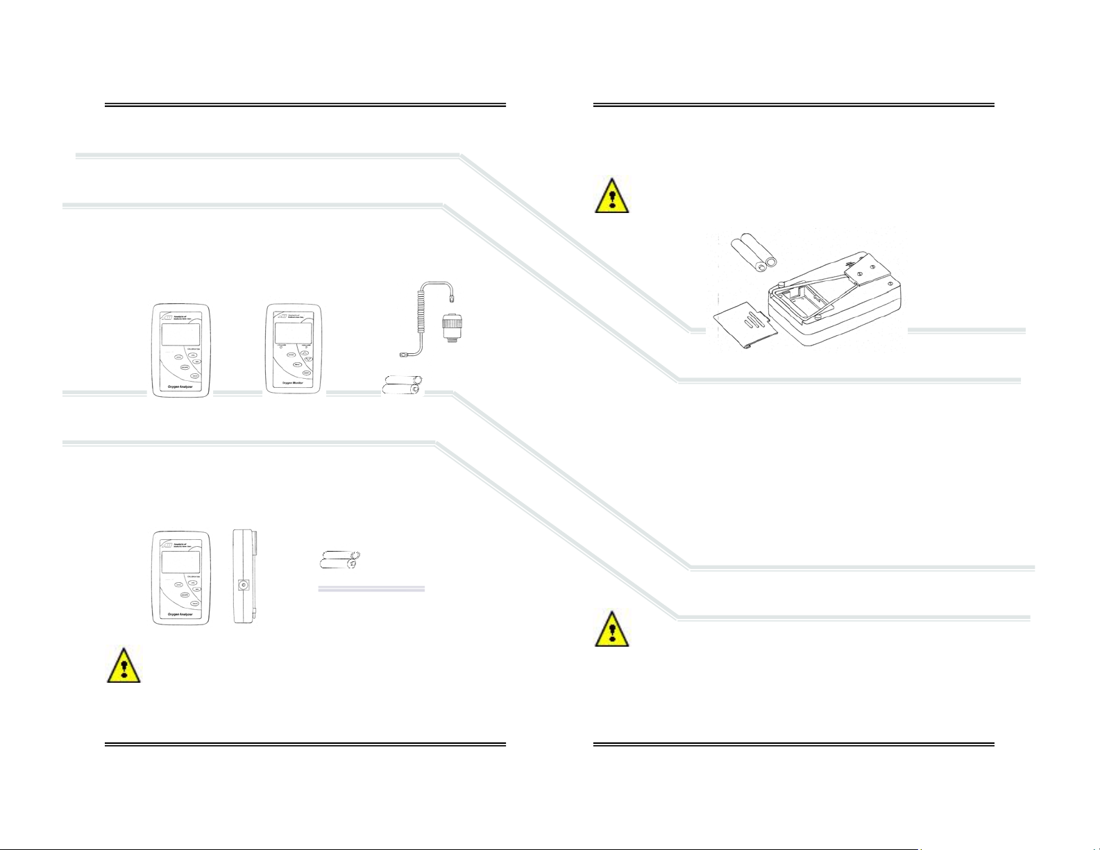
4.1.1 AII-3000 A, AII-3000 M:
ENCL-1061 V-mount retainer (attached)
ENCL-1066 Tripod wire stand (attached)
AII-11-60 Oxygen Sensor
BATT-1008 Battery, AA 1.5V Alkaline (Qty 2)
CABL-1006 Cable, Coiled Phone Jack
P-1087 Instructions for Use
4.1.1 AII-3000 AHC, AII-3000 MHC:
ENCL-1061 V-mount retainer (attached)
ENCL-1066 Tripod wire stand (attached)
AII-11-60-HC Oxygen Sensor (installed inside analyzer)
BATT-1008 Battery, AA 1.5V Alkaline (Qty 2)
TUBE-1019 Tubing, 7/32” OD Tubing 3 ft.
P-1087 Instructions for Use
Inspect t he box and cont ents for shippi ng damage. If t he device or
compone nts app ear dam age d, do not a ttem pt to oper ate t he devi ce -
contact the manufacturer immediately, refer to section 9.
OR
AND
AND
4.2 Install Batteries
All devices are powered by two 1.5V AA alkaline batteries which must be installed before the device can be operated.
The battery compartment is located at the rear of all devices. Initially
this proc edure c an be som ewhat dif ficult. C are sho uld be take n not to
damage the case when removing the battery compartment cover.
4.2.1 Procedure:
1. Remove the device and the (2) AA 1.5V Alkaline batteries from the foam
shipping container.
2. Turn t he devi ce over so the shortest raised line on the batt ery co mpartment cover is pointing away from you.
3. Lift the tripod wire stand up and away from the case.
4. Grasp the c ase wit h both hands, use y our thum bs pres s dow n firm ly on
the raised lines and push the battery compartment cover away from you.
5. Locate the positive (+) and negative (-) terminals on the battery.
6. Assure the battery contacts are clean.
7. Ali gn one batt ery’s posi tive (+) termin al with t he corr espondin g (+) battery sy mbo l m o lded into the cas e.
8. Insert the battery into the compartment.
9. Repeat with the remaining battery.
10. Replace the battery compartm ent cover, make sure it snaps into p osition
and is secured flush against the case. Replace the wire stand as required.
Replac e the bat teri es w ithi n t we nty- four (24) ho ur s of th e batt ery sym bol appearing on LCD display because batteries decline at different
rates. Calibrate the device afte r rep lacing the bat te r ies.
6
7
Page 6

4.3 Install Oxygen Sensor
The device cannot function until the oxygen sensor is installed. Once installed,
allow the sensor to stabilize for 15-20 minutes in ambient air before attempting to calibr ate the device.
NEVER - Attempt to open, repair or service the oxygen sensor.
Refer to Sect ion 3 f or hi nts an d warni ngs co ncer nin g th e han dli ng an d
environmental considerations of the oxygen sensor and the device.
4.3.1 AII-3000 A/M:
1. Remov e the contents from the shipping conta iner as shown in section 4.1
and check for damage .
2. The coiled cable uses a common RJ11 phone jack at both ends, making a
bad connection impossible.
3. Inst all the sensor awa y from any humidifyin g device to pr event moi sture
from condensing on the sensing surface and assure accurate calibration
and oxygen readings.
4. Connect one end of the cable to the device in the same manner you
would co nnect a t elephon e. Simply f i n d and re gi s t er the male pl ug at the
end of the coiled cable and insert it into the mating female jack on the
side of the device.
5. Connect the other end of the cable to the sensor in the same manner.
6. For diffusion sampling of static, ambient or controlled atmospheres –
simply expose the oxygen sensor to the atmosphere to be sampled.
7. For sampling breathing circuits with flowing gas, position the sensor
vertically for optimum results. Avoid letting the gas stagnate and facilitates the flow of g as across t he sensing ar ea of t he sensor to produ ce a
more accurate measurement of the gas stream to be measured.
8. Install the tee-adap ter in the breathing circuit.
9. Screw the flow diverter to the sensor.
10. Ensure the o-ring is lightly lubricated for ease of entry and a tight seal
between the flow diverter and tee adapter.
11. Insert the assembled flow diverter/sensor into the tee allowing air or
100% oxygen (dry, no n-humidif ied) to f low p ast t he se nsor at a r at e l ess
than 10 liters per minute.
4.3.2 AII-3000 AHC/ MHC:
When the HC (hose connection) version is ordered, the device is shipped with
the sensor installed.
4.4 Controls
4.4.1 AII-3000 A/AHC Oxygen Analyzers
These analyzers employ a micro-processor that is controlled by five (5)
pushbuttons located on the keypad attached to front cover.
1. ON/OFF provides power to the electronics
2. ESCAPE abo r ts a previous selected option
3. ENTER se lects a menu op tion
4. 100% initi ates t he routine for CA LIBRATI ON with 100 % oxygen. T he sensor must be exposed to 100% oxygen.
5. 21% initiates the routine for CALIBRATION with air or 21% oxygen. The
sensor must be exposed to air or 21% oxygen.
4.4.2 AII 3000 M/MHC Oxyge n A nalyzers
The mo nitor emplo ys a menu drive n micr o-proces sor that i s cont rol led by five
(5) pushbuttons located on the keypad attached to front cover.
1. ON/OFF provides power to the electronics
2. MENU accesses the MAIN MENU
3. ENTER s elects a menu option, and, en ables the user to si l en ce the a udi bl e
alarm quickl y wit hout havi n g to navigate through the menu(s)
4. DOWN ARROW scrolls down the menu options
5. UP ARROW sc rolls up the menu op tions
Note: The monitor is equipped with visual and audible HIGH and LOW
(minimum set point of 15%) alarms which are controlled through the MAIN
MENU a nd are activat ed when the ox ygen val ue is 0. 1% b elow the LO alarm
set point or 0.1% above the HI alarm set point, refer to section 4.6 below.
4.4.3 Instructions and Warnings displayed by LCD
START-UP TEST – diagnostic tests of the electronics, alarm circuit
(monitors only), battery voltage and the sensor’s signal output.
SERVICE DEVICE – non-sensor failures during the start-up test.
CHECK SAMPLE GAS, CHECK CA BLE, CHECK SENSOR – sensor fails the
start-up test or becomes disconnected during operation, or if an alarms is
activated (monitor).
SAMPLING – oxygen concentration from 0-100% in the sample gas during
the normal operation.
BAT LOW – battery voltage is not adequate, replace batteries.
ALARM SET POINTS, CONDITION (set point reverses color and red LED
indicator turns on) for monitor only.
8
9
Page 7

4.5 Start-Up Test
Press the ON/OFF key o n the front panel to apply power to th e device and
initiate a complete diagnostic test of all system functions: the electronics,
feeds voltage and tests the alarm circuit (monitor only below right) internally,
confirms the battery voltage is ad equate to power the circuit, and, the sensor’s signal output is within specifications.
START-UP TEST
ELECTRONICS - PASS
ALARMS - N/A
BATTERY - PASS
SENSOR - PASS
Following successful Start-Up Test the devices default to the SAMPLING mode.
20.9 %
SAMPLING
With the exception of the ALARMS for the AII-3000 M/MHC (above left) the
tests and resulting displays are the same.
Note: Any START-UP TEST failure requires the user to take corrective
action before continuing or attempting to use any device.
4.5.1 Electronics, Alarms (AII-3000 M/MHC) o r Ba t t e ry Failure
If any of these START-UP TESTs ar e unsuccess ful, the follow ing display instructs th e user to SE RVIC E DEVIC E. The f oll owing di splay i s the same f or all
models.
ELECTRONICS - FAILED
SENSOR - FAILED LOW
20.9 %
LO 15% HI 50%
START-UP TEST
ALARMS - FAILED
BATTERY - FAILED
SERVICE DEVICE
START-UP TEST
ELECTRONICS - PASS
ALARMS - PASS
BATTERY - PASS
SENSOR - PASS
SAMPLING
4.5.2 Sensor Failure
Sensor failure can result from multiple causes; the user’s failure to connect a
sensor or sensor cable, a defectiv e sensor cable or a sensor with an output
outside specification.
SENSOR - FA ILED LOW is one of the po ss ible unsucces s ful START-UP TESTs as
illustrated previo usly and displays additional warning s as follows .
4.5.2.1 AII-3000 A/AHC Oxyge n A nalyzers
The LCD alternately displays the fo llo wing until the problem is corrected.
Corrective action:
1. Expose the sensor to air or a gas containing approximately 20.9% oxygen
2. Connect or replace the cable connecting the sensor to the analyzer
3. Connect or replace the oxygen sensor
4.5.2.2 AII-3000 M/MHC Oxygen Analyzers
Perform s th e sam e rou ti ne an d requi r es th e sam e cor r ectiv e acti on as th e analyzers above with additional indicators related to the monitor’s alarm feature.
In addition to the alternating LCD display, the LO ALARM becomes active and:
0.0 %
ALARM
0.0 %
ALARM
LO 15% HI 50%
CHECK SAMP LE GAS
CHECK SAMP LE GAS
LO 15% HI 50%
CHECK CABLE
CHECK SEN SO R
ALARM
CHECK CABLE
CHECK SEN SO R
ALARM
LO ALARM value and background alternately reverse colors on the LCD
RED LED bel o w th e LO ALARM value light s up and begins fl as hing
Audible alarm begins beeping
The audible alarm can be disabled for two (2) minutes (unlimited times) by:
1. Press the MENU key on th e fr ont panel
2. Press the UP/DOWN arrow to select ALARMS AUDIBLE
3. Press the ENTER key to toggle to ALARMS SILENT mode
10
11
Page 8

4.6 Alarms AII-3000 M/M HC Ox yg e n A nalyzers
The monitor is equipped with user selectable HI and LO alarm set points
which are displayed at th e bottom of the LCD. The default alarm set points
are 15% LO an d 50% HI. The L O alarm set point c an be set betw een 15%
and 99% and the HI alarm set point can be set between 16% and 100%.
Alarm s et points may be adj usted in 1% i ncrements by pressing a nd holding
the UP/ D OWN A R ROW keys, see below . T he A RROW k e ys are dis abl ed wh en
the alarm set points are within 1% of e ac h other to pre ve nt the HI a larm f rom
being set below th e LO alarm. T he HI alar m may be disable d by atte m pti ng t o
select a HI alarm set point above 100% to facilitate flushing patients after
anesthe s ia. In this mode the LCD continua lly displays HI O FF.
The AII-3000 M/MHC Ox ygen Analyzers are equip ped with four (4) indicators
that activate when oxygen conc entrations are 0.1% below the LO alarm set
point or 0.1% above the HI alarm set point.
1. LCD alternat es between the ALA RM mode with an oxy gen reading 0.0%
and reco mm endation as illus trated in sections 4.5.2.1 and 4.5. 2.2
2. Alarm value and background alternately reverse color on LCD
3. Red LED below the alarm value lights up and begins flashing
4. Audible alarm begins beeping
4.6.1 Setting Alarm Set Points
1. Fr om the SA MPLING mode pr ess MENU
to display the MAIN MENU
2. Press the UP/DOWN arrow keys to
highlight SET ALARMS
3. Press ENTER to select SET ALARMS
4. LO alarm value is highlig hted by default
5. Press ENTER to skip the LO alarm (and
proceed to t he HI alarm) or pres s the
UP/DOWN arrow keys to change the
alarm set point
6. Press ENTER to save LO alarm set point
and move to select the HI alarm
7. Pres s ENTE R to s kip t he HI al arm ( and
return to SAMPLING mode) or press the
UP/DOWN arrow keys to change the
alarm set point
8. Press ENTER to save HI alarm set point
and return to SAMPLING mode
9. If no key is pressed within 5 seconds,
the LCD returns to the SAMPLING mode
20.9 %
SAMPLING
LO 15% HI 50%
MAIN MENU
CALIBRATE
SET ALARMS
ALARMS AUDI BL E
LO 15% HI 50%
SET LOW/HIGH ALARM
USE UP/DOWN ARROWS
TO ADJUST VALUE
TO SKIP - PRESS ENTER
LO 15% HI 50%
4.7 Calibration
Electro chem ical oxy ge n s ensors ge ner at e sli ghtl y di ff erent sign al out puts under
identical conditions due to variations in the thickness of the sensing membrane
and manufac turing process.
Simulate the application for optimum accuracy: Review Sections 3
Safety Warnings and 5.2 Application Considerations before proceeding.
The de vices are d esigned to meet th e requireme nts for bo th ambi ent
and el evated oxyge n measurements b ut should NEVER be calibrated
with air or 21% oxygen with the intent of taking oxygen me asurements
at oxyge n levels above 30% oxygen.
Accordin gly, the d evices may be calibr ated with ei ther air (20.9%) or
100% oxygen which r equires the user to m ake a conscious decision to
bypass or skip the recommended 100% oxygen calibration.
Set-Up:
AII-3000 A and AII-3000 M refer to section 5.4.1 Flowing Gas
Streams or 5.4.2 Static Atmospheres (shown with optional flow
diverter and tee).
AII-3000 AHC and AII-3000 MHC refer to section 5.4.3.
12
13
Page 9

Procedure
AII-300 0 Ser ies O xy gen A nal yz ers em plo y th e id entic al cali bra tion r o utine and
displays but they differ slightly in the way they arrive at the display that initiates calibration routine. Refer to Set-Up illustration and references above for
gas connections.
1. AII-3000 A/AHC - Press the 21% key under
the word CALIBRATION on the front panel.
1a. AII-3000 M/MHC - Requires navigating its menu to reach the
display that initiates the calib ra t ion routine .
a. From the SAMPLING menu, press
MENU to display the MAIN MENU
b. Press the UP/DOWN arrow keys to
highlight CALIBRATE
c. Press ENTER to select CALIBRATE (the
four (4) alarm indicators are disabled
during the calibration routine)
Both of the above produce the following display which initiates the
calibration routine.
3. The above prompt remains on the display until:
a. The operator presses ENTER to proceed or
b. The ESCAPE key on the AII-3000 A / A HC or the MENU key on the
AII-3000 M/MHC to abort and return to the SAMPLING mode.
4. Expose the sensor to a known source of fresh ambient air or certified 21%
(dry, non-humidified) oxygen nitrogen mix bu t not the oxygen enriched
room air commonly found in hospitals.
5. Once a suitab le calibra t ion gas is intro-
duced, press ENTER to initiate calibration
as displayed right and disable the key
pad (to prevent the calibration routine
from being interrupted).
6. This display appears for sixty (60) seconds
to allow the sensor to s tabilize before
the microprocessor takes the final reading.
20.9 %
INTRODUCE AIR/21% OXYGEN
OBSERVE TREND
PRESS ENTER TO CAL
14
LO 15% HI 50%
MAIN MENU
CALIBRATE
SET ALARMS
ALARMS AUDI BL E
20.9 %
AIR CALIBRATION
IN PROCESS
7. If the calibration is successfu l, the display below left appea r s fo r
three (3) seconds before defaulting to the display below right:
20.9 %
8. The display above right requires a decision by the user (refer to
warnings at the beginning of section 4.7) to press ENTER and
skip the 100% O2 calibration and return to the SAMPLING mode;
or, wait ten (10) se conds for the following display:
9. Repeat steps #3 through #6 using a certified source of 100% oxygen.
10. If the calibration is successful, the display
at right appears for five (5) seconds before
defaulting to the SAMPLING mode.
Calibration Fails
An unsuccessful calibration can be caused by
several problems as displayed at right:
If after three (3) unsuccessful attempts to
calibrate: review section 7 for poss ible causes
and corrective action or co ntact Advance d Instruments Inc. at 909-392-6900.
To abort the RETRY press ESCAPE (analyzer) or MENU (monitor). Do
not proceed until the ana lyzer is calibration successfully.
AIR CALIBRATION
SUCCESSFUL
20.9 %
INTRODUCE 100% O2
OBSERVE TREND
PRESS ENTER TO CAL
15
TO SKIP 100% O2 CAL
PRESS ENTER
FOR 100% O2 CAL
WAIT FOR NEXT
DISPLAY
100 %
OXYGEN CALIBRATION
SUCCESSFUL
AIR / 100% O2 CALIBRATION
FAILED
- CHECK CAL GAS
- CHECK CABLE
- CHECK SENSOR
RETRY - PRESS ENTER
Page 10

4.8 Mounting
Every analyzer and monitor is equipped with a male dove tail bracket and
triangular shaped th ick metal wire s tand secured to the rear of the enclo s ure.
Tripod W i re Stand
Secured b etwe en b ump er f eet o n eith er s id e o f t he b atter y com part m ent i s a
triangular shaped thick metal wire stand that is hinged under the dove tail
bracket secured at the opposite end of enclosure.
Unsnap the triangular thick metal wire stand from between the bumper feet
and pull it away from the enclo s ure to form a tripod which allows the dev ice to
sit upright on any flat surface
Dove Tail Bracket
The male dove t ail bracket is s ecured to th e rear of the enclosure with two
screws. The 1” female dove tail pole bracket (HRWR-1075) is an optional accessory that is commonly found in medical applications. The v-shaped male
componen t simply slide s into and out of the pole mounted female section.
5 Operation
5.1 Principle of Operati on
The AII-3000 Series Oxygen A nalyzers utilize an electrochemical galvanic fuel
cell type oxygen sensor of the type that is extensively used to measure oxygen
concentrations from 0% to 100% in gas streams. Oxygen, the fuel for this
electro chemical tra nsduc er, di ffus ing i nto t he s ensor t hrou gh a gas p ermeabl e
membra ne react s chemi cally a t the s ensing electrod e to produce an elec trical
current output pr oportio nal to the ox ygen concentration in t he gas phase. T he
sensor has an absolute zero meaning that when no oxygen is present to be
chemically reacted th e LCD displays 00 .0 oxygen.
The sens o r’ s s i gnal o utput i s l i near over the e nti r e r a nge, r em ai ns vi rt ual l y constant over th e specified us ef ul li fe and drops of f s harpl y at the end. Th e sensor
itself re quires no mainte nance and is simply r eplaced at the end of its useful life
like a battery. Inasmuch as the sensor is a transducer in its own right, its expected life is not affected by whether the analyzer is ON or OFF.
The relationship between the sensor’s signal and changes with the oxygen
concentration is both proportional and linear, thus allowing single point calibration. Ot her factor s t hat can af f ect the si gn al o utput are descr i be d i n Secti on 5 .2
Application Considerations and Section 3 Safety Warnings which should be read
before use.
Historic ally, the expected life of galvan ic fuel type sensors has been specifie d as
“in air (20.9% O
type s ens or i s inv ersel y aff ect ed b y c ha nges i n t he aver ag e o xyg en conc e ntration, t em p er ature and pressure it i s expos ed t o duri n g its useful l i fe. For ex am ple, the AII-11-60 sensor has a 60 m onths e xpected life i n air (20.9 % oxygen)
at 25°C a nd ambient pres sure, howe ver, in a 100 % oxygen atmo sphere the
expected life is 12.6 months [60mo/(100%/20.9%)].
AII-300 0 Series Oxyg en An alyzer s are batter y pow ered b y (2) AA alkal ine ba tteries a nd controll ed by a state-of- th e- art micr opr ocessor . The batt eries pr ovi de
enough power to operate the analyzer continuo usly for approximately 1,200
hours. Both devices utilize a membrane type keypad for users to communicate
commands to the microprocessor. The monitor is menu driven to accommodate
the alarm functions. The digital electronics provide features such as system
diagnostics, warning indicators, controls and an alarm capability for continuous
monitoring that enhance both safety and effectiveness. The design criteria,
quality pr ogr am a nd per for ma nce f eatur es ensur e rel iabl e a nd a ccur ate o xy gen
measurements.
) at 25°C and 760mm Hg”. The actual life of any galvanic fuel
2
16
17
Page 11

5.2 Application Consideratio ns
Effect of Temperature
All mem bra ne clad electro ch emi cal se nsor s are t em perat ur e depe ndent d ue t o
the expa ns i o n and contr action o f the Teflon sens i ng mem br a ne. A s result m o re
or less of the sample gas including oxygen to be reacted diffuses into the sensor. The oxygen s ensor’s electrical current signal output varies linearly with
oxygen concen tr ati o n . T he s i gnal als o varies with changes in am bi en t tem perature. The temperature coefficient is typically 2.54% of the signal or reading per
degree C change in temperature.
The tem peratur e depe ndent cur rent si gnal ou tput is compens ated by us ing a
resistor-thermistor network. With a proper resistor-thermistor network, the
signal can b e compens ated to w ithin +
5% of the oxygen reading over the 545°C tem p er a t ure range. Thi s i s the wors e case s i tuat i on when goin g f r o m o n e
extreme of the operating temperature range to the other. The error will be
elimi nated wh en t he ther mis tor in the t em per atur e com pe nsa ti on netw ork a nd
the elec t r olyte inside the sensor reach therma l equ ilibrium in appro ximately 4560 minutes.
Erroneous oxygen readings can result if the gases flowing over the
sensing area of the sens or are not at am bient t em perature. This occ urs
because the sens or is expos ed to dif ferent tem peratur es. The s ensi ng
area of the sensor is o-ri ng seal ed in t h e heat ed breathi ng circ ui t and the temperature compensation network at the rear of the sensor is exposed to ambient
temperature.
Effect of Pressure
Electrochemical sensors a ctu all y m eas ure th e par tial pressure, not th e p ercen tage, of o xy ge n in the gas s t ream they are e xpo sed to. Th es e sensors are a cc urate at any press ure provid ed the press ure is cons tant and the analyz er has
been calibrated at the same pressure as the sample gas measured.
For example, when moving an analyzer calibrated at sea level into the mountains caus es the anal yzer to display an decre ase in the ox ygen readin g displayed. When if fact, the decrease in the reading displayed is not related to a
change in the oxygen percentage but to the decrease in partial pressure
(corresponding to the increase in total pressure) at altitude.
Calibrat e at th e temper ature a nd pres sure ( altitu de) at w hich t he ana-
lyzer will be operated.
Effect of Humidity
The an alyzer is no t affect ed by non -condensi ng relativ e humidit y (RH). Ho wever, the use of a humidifier to introduce water vapor and increase the moisture level of the gas mixture does affect the oxygen concentration and the
resultant reading dis played by t he anal yzer. The addition of water vapor increases the total pr es s ure thereby di l uting or decre as i ng the oxygen conce ntr ation of the ga s mi xture resulting in a lower oxygen reading.
Effect of Condensati on
Excessiv e co nde nsati on col lecti ng on t he sens ing ar ea or t he el ect ri cal con nections at the rear of the sensors can a dversely imp act the performan ce of electrochemical sensors. Conde nsation blocks the di ffusion pat h of oxyg en into th e
sensor a nd ca n re duce t he oxy gen r eading to 00 .0 if the cond ensat ion cov ers
the entire s ensing ar ea. Co ndensation o n t he el ectrical c onnections at the re ar
of the sensor can affect oxygen readings. Remedy either situation by shaking
out the condensation and allowing the sensor to air dry.
Erroneously characterized in many instances as a sensor f ailure, exc essive condensatio n i s r emedied by gentl y w i pi ng away t he condensati on wit h a s oft cloth
or simply allo wing the sensor to air dry.
Effect of Electromagnetic Radiation
Tested over a 26 MHz to 100 0 MHz elect rom agnetic fiel d, th e anal yzer i s susceptibl e at al l fr equ e nci es t ested exce pt t hose between 930 an d 99 0 MHz .
Never operate the analyzer near equipment capable of emitting high
levels of electromagneti c radi at i o n. Do no t continue t o oper ate th e analyzer if the reading becomes unstable.
5.3 Calibration
Calibrating the analyzer or monitor during normal operation involves the same
precautions and procedures as thos e descri b ed in Sections 4 . 7 Start- up Cali bration with the same cautio ns to review Sections 3 S afety Warnings a nd 5.2 Applicatio n Considera t ions.
5.4 Sampling
Assuming the START-UP instructions are followed and the tests are completed
successfully the devices de fault t o the SAMPLIN G mode.
Never operate the analyzer if the reading is unstable or if a malfunction
is suspected. If calibration is required as indicated herein, do not proceed until the analyzer is c alibration succ essfully.
18
19
Page 12

5.4.1 Flowing Gas Stream s
1. Place the sens ing are a of the s ensor i nto the g as str eam to b e analyzed
upstream of any humidification equipment.
2. Assure that the flow rate of the gas stream does not exceed ten (10) liters
per minute. Exceeding ten (10) liters per minute generates backpressure.
3. Check the gas stream and particularly the mechanical connection for leaks
that dilute the gas stream with a mbien t air.
4. Assure there are no restrictions in the circuit downstream of the sensor
that could generate backpressure on the sensor.
5. Use the optional flow diverter along with the op-
tional tee adapter and positi on the s ensor v ertically
for optimum results, as s hown right. The flow diverter avoids stagnation and facilitates the movement of gas to and from the s ensing area of the
sensor thereby producing a more accurate measuremen t of the g as stream to be measured.
6. Install the tee-adapter in the breath ing c i rcuit.
7. Screw the flow diverter to the sensor.
8. Ensure the o-ring is lightly lubricated for ease of
entry and a tight seal between the flow diverter and
tee adapter.
9. Insert the assembled flow diverter/sensor into the tee allowing air or
100% oxygen (dry, non-humidified) to fl ow past the sensor at a rate of 58 liters per minute.
10. Once th e sensin g area of the se nsor is expose d to the gas stre am allo w
approximately sixty (60) seconds for the reading to stabilize and observe
the reading displayed by the LCD.
11. Refer to Section 8.1 for a variety of accessories that provide a several
methods of sampling flowing gas streams.
5.4.2 Static Atmospheres
Remove the flow diverter, not needed. Failure to remove the flow diverter will
dramatically slow the response time of the sensor.
Expose the sensing area of the sensor to the atmosphere allowing appro xi-
mately sixty (60) seconds for the reading to stabilize and observe the
reading displayed by the LCD.
If placing the entire sensor inside the controlled atmosphere review
Section 5.2 Application Consideration, Effect o f Temperature.
5.4.3 AII-3000 AHC and M HC (Inte g ral Oxygen Sensor)
AII-300 0 AHC and MHC wit h thei r in tegral oxyg en s ensor req uires conne cting
the ¼” tubing su pplied (section 4.2.1 a bove) with the device to a ¼” hose
barb attac hed to a pressure regulator controlling a source of gas flowing at less
than 10 liters per minute.
5.5 Alarms (AII-3000 M/MHC):
The mo ni to r i s eq ui pped w i th user s electable HI a nd LO alar m s e t p o i nts w hi c h
are displayed at the bottom of the LCD. Section 4.6 describes the operation
and procedure for setting the alarms in detail.
6 Maintenance
Review Section 3 Safety Warnings and Section 7 Troubleshooting for
guidelin es on servicing the devices.
6.1 Serviceability
Do not op en t h e m ain com partm en t of t he anal yz er, as it cont ai ns no s er vic eable parts inside. Never attempt to repair the analyzer or sensor by yourself as
you may damage the analyzer which could void the warranty.
6.1.2 Cleaning / Reuse Inst ructions
Clean th e devic e, oxyge n sens or and accessori es with a soft cloth dam pened
with either water or mild isopropyl alcohol solution (70% isopropyl alcohol
solution in water), if necessary, before re-use. Allow the components to air-dry
after cleaning .
Note: The Home Care Kit is not intended for patient use, it is intended solely
for conf irming t he O
cleaning instructions apply.
6.2 Battery Replacement
The an alyzers an d moni tor are po wered b y two A A alkali ne batt eries wi th an
approximate life of 1,200 hours. A low battery indicator circuit m onitors the
battery suppl y vo l ta ge and sends a sign al di rectly t o the LC D when the bat t er y
voltage reaches a preset level that activates the battery symbol in the LCD.
The bat t eri es ar e h o used i n a separate co m p ar tment l ocated at the rear o f the
device and are accessible by sliding the removable cover.
concentration in Oxygen Concentrators. Accordingly, no
2
20
21
Page 13

Initially this procedure can be somewhat difficult. Care should be taken
not to damage the case when removing the battery compartment cover.
6.2.1 Procedure:
1. Turn the device over so the
shortest raised line on the bat tery
compartment cover is pointing
away from you.
2. Lift the tripo d wire stand up and
away from the case.
3. Grasp the case with both hands
and using your thumbs press
down fir mly on the rai sed li nes and push t he battery compart ment cover
away from you.
4. Locate the positive (+) and negative (-) terminals on the battery.
5. Assure the battery contacts are clean.
6. Ali gn one batt ery’s posi tive (+) termin al with t he corr espondin g (+) bat-
tery sy mbo l m o lded into the cas e.
7. Insert the battery into the compartment.
8. Repeat with the remaining battery.
9. Replace the batter y compartment cover, make sure it snaps into position
and is secured flush against the case. Replace the wire stand as required.
10. Calibrat e the device after re placing the ba tteries.
6.3 Oxygen Sensor Replacement
The desi gn of th e electr onics is int ended f or only t he An alytical Ind ustries Inc.
AII-11-60 or AI I-11-60-HC Oxygen Sensors. Use of a different o xygen sensor
may result in an erroneous oxygen reading.
NEVER - Open th e oxygen s ensor or probe t he sensin g surfa ce, refer
to Section 10 in the event the sensor should leak and someone comes
in contact with the electrolyte from inside the sensor.
6.3.1 Procedure AII-3000 A a nd AII-3000 M - External Sensor
1. Disconnect the cable from the old sensor just as you disconnect a tele-
phone jack from a wall plug.
2. To connect the new sensor simply fi nd and register the male plug at the
end of the coiled cable and insert it into the mating female jack at the rear
of the senso r unt il it m ates or snaps into place.
3. Calibrate the device after replacing the oxygen sensor.
6.3.2 Procedure AII-3000 AHC and AII-3000 MH C - Int e g ral Sensor
1. Tools required: small bladed screwdriver.
2. Plac e the device face down on a flat surface.
3. Remove the two (2) screws from the upper cor ners of the rear of the
device.
4. Move th e tripod up, rem ove the batt ery compartment co ver (see Battery
Replacement) and remove the two (2) screws located on either side.
5. Pull the rear section up ¼”-½”, turn it over and lay it next to the other
section.
6. Loc ate the w hite co nnecto r at the e nd of the f our (4) wires runnin g fr om
the sensor (the cylinder with the white label) to the top of the PCB.
7. With your left for finger and thumb, grasp the sides of the back end of the
white connector where it is soldered to the PCB.
8. With yo ur rig ht fore f inger and thumb, grasp t he sides of the sec tion of
the white connector where the four (4) wires from the sensor terminate.
9. Separate the connector - hold the white connector section your left hand
while gently pulling and wiggling the white connector section with your
right hand until it un lo cks.
10. The oxygen sensor inserts into an adaptor (identified by a round recess
with a cylindrical hose adapter in the center) that slides into grooves
molded into the side of the case.
11. Hold the r ear section of the cas e down, gr asp the sq uare edges of the
adaptor, lift up (lift straight up so as not to strip the grooves molded into
the adaptor and case) and remove the adaptor and oxygen sensor as a
single component.
22
23
Page 14

12. Once th e adapt er and ol d sensor h ave bee n removed f rom the c ase, ho ld
the label of the s ensor , agai n grasp t he s quare ed ges of the ada ptor and
pull – to separate the old sensor from the adaptor.
13. Remove the new oxygen sensor from the plastic shipping container.
14. Install the new oxygen sensor by reversing steps 12 through 3.
15. Calibrate the device after replacing the oxygen sensor.
7 Troubleshooting
If the recom men ded corr ectiv e action does no t resol ve the probl em retur n the
device to the factory for service.
Symptom Corrective Action
Device appears to be physically dam age d
No digital display when analyzer is turned ON
Battery symbol on LCD display
LCD display reads 00.0
No response to keypad command
Cannot turn device OFF
Turn device ON – if it successful passes
START-UP TEST and calibrates – proceed.
Install b attery
Replace bat tery
Check battery polarity
Check and/ or cl ean battery contact s
Replace battery and calibrate device
Install sensor
Check electrical conn ections
Assure electrical connections are dry
Replace bat tery
Calibration routine in process – escape or
wait until completed
Symptom Corrective Action
Reading displayed by LCD
drifts during calib r ation
Analyzer reading climbs after
calibration in 100% dry oxygen when exposed to air
20.9%
After calibration in 100% dry
oxygen, analyzer reading
drifts more than 2% over 8
hours
Reading displayed by LCD
does not change when oxygen leve l cha nges
Reading does not stabilize or
fluctuates erratically
Wait 5 minutes and repeat calibration with
sensor placed on flat surface (not in your
hand)
Check integrity of gas delivery system
Check sensor’s front o-ring seal
Verify calibration g as in not humidified
Remove moisture covering sensor
Replace sensor, repeat calibration
Allow the sensor to stabilize for 5 minutes in
100% dry oxygen and recalibrate
Check p r im ary oxygen delivery de vice
Replac e se nsor t ha t is near i ng th e e nd of it s
useful life
Replace sensor
Relocat e analyz er aw ay sour ce of radio f requency or electromagnetic radiation emissions. Tested over a 26 MHz to 1000 MHz
electromagne ti c f ield, th e a nalyzer i s sus ceptible at all frequencies tested except those
between 930 and 990 MHz.
Check sensor connection
Check cable connection
Wait 5 minu te s and re peat calibration
Replace sensor, repeat calibration
Do not attempt to use the analyzer and
return the analyzer for service.
24
25
Page 15

Symptom Corrective Action
Reading displayed by LCD
does not change when calibratio n control is adjusted
Reading displayed by LCD is
very low
Alarms continuously activated
Replace sensor
Check sensor connection
Check cable connection
Replace sensor
None – Normal operation, confirm set points
Abnormal Adjust alarm set points
Remove moisture covering sensor
Check sensor connection
Check cable connection
Check integrity of gas delivery system
Check sensor’s front o-ring seal
Verify calibration g as in not humidified
Verify flow rate is 4-5 liters per minute
Replace sensor
Replace cable
8 Specifications
Accuracy: +2% of FS range under constant conditions
Analysis: 0-100% oxygen
Area Classification: General purpose
Alarms:
Calibration: Air or 100% oxygen after 8 hours of continuous use.
Compensation: Temperature compensated
Connections: A/M models: 1x16mm thread; HC models: Tubin g 1/4”
Controls: Soft touch keypad for ON/OFF and menu function
Dimensions: 3.6 x 5.9 x 1.6”; weight 10 oz. (280 grams)
Display: 3-1/2 digit backlit LCD 2.5” x 1.5”; resolution 0.1% O
Flow Sen sitivity: None bet ween 0.2 to 10 liters per minute
Humidity: Non-condensing 0-95% RH
LED Indicators: A models - none; M models - upon activation of alarms
Linearity: +
Pressure: Inlet – (A/M) ambient, (HC) regulate; Vent - atmosphe r ic
Power: 2 AA Alkaline batter i es ; 1, 2 00 hours co ntinuo us us e
Respon se Time: 90% of fina l FS reading in 9 seco nds
Sensitivity: < 0.5% of FS range
Sensor: A/M models: AII-11-60 or HC models: AII-11-60-HC
Expected Life: 60 months in air at 25ºC and 1 atmosphere
Storage Temp.: -20º to 60ºC (-4ºF to 140ºF) on intermittent basis
Temp. Range: 5º to 45ºC (41ºF to 113ºF)
Warm-up Time: None
Warranty: 12 months analyzer; 12 months sensor
A models – none; M model s - Us er adjus tabl e HI 1-100%
and LO 0-99% alarms; 120 second alarm silence; HI
alarm defeat for 100% O
1% under constant conditions
measurements
2
2
26
27
Page 16

Expected Sensor Life
Consider s the f ul l r ang e of th e s enso r’s si gnal , exam ple 7-13 m V. Oxy ge n s ensors are co nfigured to meet th e published, s ee preceding pa ge, specificati on
which dist r ibutes the overall sensor life as follows:
- 60 months Expected Service Life (915,420 oxygen % hours)
- 6 months Recommended Storage Life period (91,542 % oxygen hours)
- 2 months margin of error
Therefor e, the Recommend ed Storag e life per iod should not be co nsidered a
perishabl e shelf life. Op erating at the spe cified par ameters of oxyg en conce ntration (air 20.9%), temperature (25⁰C/77⁰F) and pressure (1 atm/bar), the
sensor will o perate for app r o ximately 68 m onths whether in s torage or in use .
The purpo se of the Rec ommended Storage Life p eriod is to ensure the user
derives the E xpected Life of 60 months (9 15,420 % oxyg en hours) a nd does
not lose the benefit of the warranty.
Warranty
The 12 month (183,084 % oxygen hours) w arranty period (b egins with shipment from the factory and is limited to the first claim submitt ed) is based on :
8.1 Spare Parts & Accessories
AII-3000 A, AII-3000 M
Spare Parts: Spare Parts:
AII-11-60 Oxygen Sensor AII-11-60-HC Oxygen Sensor
BATT-1008 Battery (2x) 1.5V AA BATT-1008 Battery (2x) 1.5V AA
P-1087 Instructions for Use P-1087 Instructions for Use
A-1162 PCB Assy Main A-1162 PCB Assy Main
CABL-1006 Coil Cable TUBE-1019 7/32” OD Tubing 3’
AII-3000 AHC, AII-3000 MHC
Optional Acces sories - See opposing page
CC-1072 Carrying Case
28
29
Page 17

9 Warranty
Coverage
Under nor mal o perati ng co nditions , th e anal yzer an d sens ors ar e war rante d to
be free of defects in materials and workm anship for the p eriod speci fied in the
current published specificat ion s . To make a warrant y claim, you must return the
item properly packaged and postage prepaid to:
Advanced Instruments in their sole discretion shall determine the nature of the
defect. If the item is determined to be eligible for warranty we will repair it or,
at our option, replace it at no charg e to you. If we choos e to repair your item,
we may us e new or reco ndition ed repl acem ent par ts of t he same o r upgr aded
design. This is the only warranty we will give and it sets forth all our responsibilities, there are n o other express or implied warran ties.
The w arra nty b egi ns wi th t he dat e of shi pm ent fro m A dv ance d Ins tr ume nts, is
limited to the first customer who submits a claim for a given serial number
which must be in place and readable to be eligible for warranty and will not
extend to more than one customer or beyond the warranty period under any
conditions.
Exclusions
This warranty does not cover normal wear and tear; corrosion; damage while in
transit; damage resulting from misuse or abuse; lack of proper maintenance;
unauthorized repair or modification of the analyzer; fire; flood; explosion or
other fa ilure to follow t he Owner’s Manual.
Limitations
Advanced Instruments shall not liable for losses or damages of any kind; loss of
use of t he analyz er; incide ntal or co nsequenti al losses o r damages ; damages
resulting from alterations, misuse, abuse, lack of proper maintenance; unauthorized repair or modification of the analyzer.
Service
Contact us between 8:00am and 5:00pm PST Mon day thru Thursday or before
12:00pm on Friday. Trained technicians will assist you in diagnosing the problem and determ i ning the appropriate course of action .
Advanced Instruments Inc.
2855 Metropolitan Place
Pomona, Ca 91767 USA
T: 909-392-6900, F: 909-392-3665
E: sales-industrial@aii1.com
, W: www.aii1.com
10 Material Safety Data Sheet (MSDS)
Product name Electrochemical Galvanic Fuel Cell Oxygen Sensor
Exposure Sealed device with protective coverings, normally no hazard
Ingredients Carcinogens - none; Potassium Hydroxide (KOH), Lead (Pb)
Properties
Flash Points Not applicable, non-flammable
React ivity Stable; avoid strong ac ids, emits fumes when heated
Health Hazard KOH entry via ingestion - harmful or fatal if swallowed;
Symptom s Eye con ta ct - burning sens at io n; skin conta ct - slick feelin g
Protection Ventilation - none; eye - safety glasses; hands - gloves
Precautions Do not remove Teflon and PCB coverings; do not probe wi th
Action KOH
Leak
10.1 Disposal
Oxygen sensors and batteries should be disposed of in accordance with local
regulations for batteries.
Completely soluble in H
eye - corrosive, possible loss of vision;
skin con ta ct - corrosive, possible che mical burn.
Liquid inhalation is unlikely.
Lead - known to caus e bir th defec ts , contact unl ikely
sharp objects; avoid contact with eyes, skin and clothing.
Use rubber gloves, safety glasses and H
surfaces repeatedly with liberal amounts of H
WEEE regulations prohibit electronic products including the Helium a nd enviro nmental s ensors fr om being placed i n househol d
trash bins.
Electronic products should be disposed of in accordance with local
regulations.
2O; ev aporation similar to H2O
2O and flush all
2O
30
31
 Loading...