

Page 1

510(k) K952736 O2 Sensor
510(k) K053407 O2 Analyzers
EN 12598:1999 / ISO 7767: 1997
(Oxygen monitors for patient breathing
mixtures – Particular requirements).
EC: Medical Device Directive: 93/42/EEC,
Annex II as Amended by 2007/47/EC,
Certificate #485CE
ISO 9001:2008, Certificate #485
Authorized EC Representative:
RGV Lda.
Rua Jose Joaquim de Freitas, 247
2750-4 04 Cas ca is-Portu ga l
Health Canada: Medical Device Regulations, F-27/ SOR-98-282
ISO 13485:2003, Certificate #485B
AII-2000 A
AII-2000 HC
Copyright © 10/10 All Rights Reserved
Analytical Industries Inc.,
2855 Metropolitan, Pomona, CA 91767 U SA.
Tel: 909-39 2-6900, Fax: 909-392-3665
e-mail: sales-medical@aii1.com, web: www.aii1.com
This manual may not be reproduced in whole or in part without
the prior written consent of Analytical Industries Inc.
AII-2000 M
Page 2

Table of Contents
1 Introduction
1.1 Indications for Use
1.2 Intended Use
1.3 Device Description
1.4 Declaration of Conformity
2 Quality Control Certification
3 Safety Warnings
4 Start-up
4.1 Contents of Shipping Container
4.2 Install Batteries
4.3 Install Oxygen Sensor
4.4 Controls
4.5 Start-up Test
4.6 Alarms (AII-2000 M Oxygen Monitor)
4.7 Calibration
4.8 Mounting
5 Operation
5.1 Principle of Operation
5.2 Application Conside ra t io ns
5.3 Calibration
5.4 Sampling
6 Maintenance
6.1 Service ability
6.2 Battery Replacement
6.3 Oxygen Sensor Replacement
7 Troubleshooting
8 Specifications
8.1 Spare Parts & Accessories
9 Warranty
10 Material Safety Data Sheet (MSDS)
10.1 Disposal
1 Introduction
Congratul a tions o n your p urch ase, t hese Ins tr ucti ons fo r U se des cri be th e pr ecautions, set-up, operation, maintenance and specifications of the AII 2000
Series Oxygen Analyzers & Monitors.
This symbol means CAUTION – Failure to read and comply with the
Instructions for Use could damage the device and possibly jeopardize
the well being of the patient and/or health care professional.
Note: Analytical Industries Inc. cannot warrant any damage resulting from the
misuse, unauthorize d repair or improper maintenanc e o f th e device.
1.1 Indications for Use
The AII 2000 S eries Oxygen Analyzers & Monitor are int ended to m easure a nd
display the concentration of oxygen in breathing gas mixtures. The intended
use is only to v er i fy, spot chec k or continuously monit or , oxyge n conce nt rat i ons
in circumstances where the oxygen concentration is controlled and set by other
medical device such as oxygen/air blenders, flow m eters or other control device.
Users m ust read th e followi ng statements as they are es sential to reducing the r is k of us e erro r du e to ergo nomi c f eat ur es of th e devi ce o r
the environment in which the device is intended to be used.
The de vices as ide ntified i n Section 1 .4 Declar ation of Co nformity have been
designed and man uf actured i n s uch a way that w h en used u nder the co ndi tions
and for the purposes intended, they will not compromise the clinical condition
or the safety of patients, or safety of the users or other persons.
Federal law restrict s this device to sale by or on the order of a physician.
Conform ity wi th ess enti al re quir eme nts has been demo nstr ate d by ver if ying th e
performance of the device under normal conditions, bench testing, pre-clinical
and simulated clinical evaluations and determining that undesirable malfunctions constitute minimal risk to patients and users.
Particular requirements for sterilization do not apply to these devices. Do not
sterilize, autoclave, liquid sterilize, immerse in any liquid or expose the device
or acce ss o r ies to steam, ethylene oxide or ra diation sterilization.
i
1
Page 3

The device is i ntended t o be re - usable. S ho ul d t h e device o r access o ri es co m e
in contact w ith p atien t bo dil y fl uids , eit her di spos e o f th e devi c e or clea n wi th
a soft cloth dampened with 70% isopropyl alcohol solution in water and allow
the components to air-dry before re-use .
The device and accessories are not intended to transport or store any medicines, bo dy l iquids or ot her s ubstan ces th at ca n be adminis tered or rem oved
from the body, and, do not contain any latex, human blood derivatives, phthalates, carcinogens or other reproductive toxics.
Calibrate the device with 100 % o xygen b efore using each da y or aft er 8 hours
of continuous use. In the event the device fails to calibrate or if the reading
becomes, do not attempt to use the device. Contact the manufacturer for
assistance.
Do not operate the a nalyzer near eq ui pm ent cap abl e of emittin g hi gh level s o f
electromagnetic radiation as the reading may become unstable.
In order to obt ain op ti mum p erforman ce, t he o peration of th e d evice m ust b e
performed in accordance with th ese Instructions for Us e. Maintenan ce should
be performed only by trained personnel authorized by the manufacturer.
Additional operating pointers are provided in Section 3.
1.2 Intended Use
The AII 2000 S eries Oxygen Analyzers & Monitors are intended to measure
and displ ay the conce ntration of o xygen in breat hing gas mi xtures. The intended use i s o nly to veri fy, s pot ch eck or co nti nuous l y mo ni tor , o xyg en co ncentrations in circumstances where the oxygen concentration is controlled and
set by other me dical d evice s uc h as o x ygen/air ble nders, f low me ter s or other
contr o l device found in the fo llo wing medical applications:
Anesthesia (refer to Section 5.2)
Respira t o ry Therapy – Ventilators, Respir ators
Neonatal & Pediatric Incubators & Hoods
Oxygen Therapy - Intensive Care
Spot Checking Concentrator
1.3 Device Description
The AII 2000 Seri es Oxygen Anal yzers and Mo nitor can be pos itioned on a
table to p or pole ( tripod wire stand and V-moun t dovetail attach ments are
mounted on the back of the device) and are readily portable from one location
to another. They provide continuous, fast, reliable and accurate oxygen measurements of up to respiratory care systems.
The devices utilize an electrochemical galvanic fuel cell type oxygen sensor of
the type t hat is extens ivel y used to meas ure o xygen co nce ntratio ns f rom 0%
to 100% in gas streams. O xygen, the fuel f or this electroch emical transduc er,
diffus ing into the s ensor thr ough a g as permeabl e membra ne reacts ch emically at the sensi ng electro de to produ ce an elect rical curr ent o utput propo rtional to the ox yg en con ce ntra tio n in the g as phas e. T he s enso r h as an absolute zero meaning that when no oxygen is present to be chemically reacted
the LCD displays 00.0 oxygen.
The sensor’s signal output is linear over the entire range, rem ains virtually
constant over t he specif ied us eful li fe and drop s off sharply at the e nd. The
sensor itself requires no maintenance and is simply replaced at the end of its
useful l ife like a ba ttery. In asmuch as t he sensor i s a transdu cer in its own
right, its expected life is not affected by whether the analyzer is ON or OFF.
A batter y pow ered st ate-of -the-ar t mi cro-pr ocess or con verts t he s ensor’ s signal output representin g t he partial pressure of ox ygen in the gas stream bei ng
analyzed. The resulting oxygen reading is displayed by a large easy to read
backlit liquid crystal display (LCD) that has a resolution of 0.1% oxygen. The
microprocessor is controlled from a keypad and provides features like system
diagnostics, warning indicators, controls and an alarm capability for continuous monitoring that enhance both safety and effectivene ss.
Prior to shipment, every device is thoroughly tested at the factory and documented in the form of a Quality Control Certification that is included in the
Instructions for Use supp lied with every device.
The manuf acturer ’s cont act info rmation and serial number o f this d evice c an
be found above the ba ttery compar tment cov er on the r ear of the d evice and
in Sect ion 2 Qu ality Control C ertificat io n.
In conclusion, Analytical Industries Inc. appreciates the opportunity to supply
this device and anticipates many years of useful service.
2
3
Page 4

1.4 Declaration of Conformity
Manufacturer:
Analytical Industries Inc.
2855 Metropolitan Place, Pomona, California 91767 USA
Tel: 909-392-6900, Fax: 909-392-3665
e-mail: sales-medical@aii1.com , www.aii1.com
Authorized EC
Repres entativ e:
RGV Lda.
Rua Jose Joaquim de Freitas, 247
2750-404 Cascais-Portugal
Product:
AII 2000, AII 2000A, AII 2000 HC, A I I 2000 TruO2 Ox ygen
Analyzers; AII 2000M Oxygen Monitor
PSR Series Oxygen Senso rs
Classification:
Directives:
IIb
Medical De vice Direct iv e 93/4 2/E EC, Annex II as am ended
by 2007/47/EC
Standards &
Certificates:
510(k) K952736 O2 Sensors
510(k) K053407 O2 Analyzers
EN 12598:1999 (ISO 7767: 1997) Oxygen devices for
patient breathing mixtures – Safety requirements
Medical De vice Direct iv e 93/4 2/E EC, Annex II as am ended
by 2007/47/EC, Certificate 485CE
ISO 9001:2008, Certificate 485
ISO 13485:2003, Cert 485A
Medical Device Regulations, F-27/ SO R-98- 282 (Cana da)
Notified Body:
AMTAC Ce r tification Services Limit ed
Davy Ave nue, Knowhill
Milton Keynes MK5 8NL
United Kingdom
CE mark affixed: February 21, 2006
We hereby declare the above product meets the provisions of the directives
and standards specified. All supporting documents are retained on the premises of the manufacturer.
Patrick Prindible, QA Ma na ger
2 Quality Control Certification
Customer: ________________________ Order No. _____________ Date: _______
Model: ( ) AII-2000 A Oxygen Analyzer
Sensor: ( ) AII-11-60 or ( ) AII-11-60-HC S/N _______________
Electronics: A-1162 PCB Assembly Main Software Version _______________
Accessories: AII-2000 A / M:
PASS
QC Test: LCD display 3-1/2 digits ……………………………………………………. ______
Battery symbol displays when battery is low ……………………….. ______
Span adjustment +
Following calibration with 99-100% oxygen and flushing with
Span adjustment +
Following calibration with air (20.9% oxygen) and exposing
Options: Item No.
FITN-1009 Tee Adapter ……………………………………………………….. _____
ENCL-1072 Carrying Case ……………………………………………………. _____
Other: _____
Delivery:
( ) AII-2000 M Oxygen Monitor
( ) AII-2000 HC Oxygen Analyzer S/N _______________
FITN-1112-1 Flow Diverter
AII-2000 HC: A-3675 Adapter, 5/32” Tube to Sensor
TUBE-1007 1/4” Tubing 7 ft. with Adapter
All units: BATT-1008 Battery, 1.5V AA (Qty 2)
P-0187 Manual, Instructions for Use ……… Included ______
ambient air, oxygen reading as displayed by LCD 20.9% +
to 99-100% oxygen, LCD displays 100% +
Overall inspection for physical defects ………………………………... ______
HRWR-1075 Dovetail Female Clamp Pole/Shelf ………………………
CABL-1006 Cable, Coiled Phone Jack
10-30% FS with 100% oxygen calibration ______
2% ____
10-30% FS with air calibration ……………….. ______
2% ……………………. ______
Qty
____
4
5
Page 5

3 Safety Warnings
ALWAYS foll ow the st atem ents bel ow as t hey ar e ess ential to redu cing the ri s k o f us e err o r due to er gonomic f eatures of t h e device o r t he
environment in which the device is inte nded to be used.
Only trained personnel who have read, understand and agree to follow
the Instructions for Use should operate the device.
Retain the Instructions for Use for future reference.
Refer service needs to trained authorized personnel. Failure to do so may
cause the dev ice to fail and void the warranty .
Inspect the device and accessories before operating and ensure: (a)
there is no evi de nc e of ph ysical dama ge; (b) the se nsor ( parti cul arl y t he
sensing s urf ace) and elect ri cal conn ecti ons ar e dry; and, ( c) the sensor is
installed and upstream from any humidifying device for accurate calibration and oxygen readings.
Calibrate: (a) with a known source of dry 100% oxygen before using
each da y or after 8 hour s of conti nuo us use; (b) when the temper atur e
or pressure of the operating environment changes; (c) if the oxygen
sensor has b een di sconne cted and r econnect ed; (d) af ter t he batt ery o r
oxygen sensor ha s been repla ce.
Sampling flowing gas: (a) install the flow diverter and the tee-adapter in
a vertical position as shown in Section 4.3 and (b) assure there is a tight
fit between the flow diverter and tee adapter.
Sampling static, ambient or controlled atmospheres such as incubators,
oxygen hoods, tents, etc.: remove the flow diverter.
Clean the device and accessories in accordance with Section 6.1.2.
Battery replacement Section 6.2: ( a) replace t he batteries within tw enty-
four (2 4) hour s of the battery symbol appearin g o n LCD di s play
calibrate the analyze r aft er replacing th e ba tteries.
Oxygen sensor installation or replacement Section 6.3: allow the new
sensor to stabilize for 15-20 minutes in ambient air before attempting to
calibrate.
Store th e de vice b y turni ng t he po wer OFF an d rem ovin g t he ba tteri es i f
the device will not be operated for over thirty (3 0) days.
Attempt to repeat the procedure that caused a perceived malfunction
and refer to troubleshooting hints in Section 7 before concluding the
device is faulty. If in doubt, contact the manufacturer for assistance.
and (b)
NEVER o perate the d evice in any m anner des cribed below doing so
may compromise the clinical condition or the safety of patients, users
or other persons.
If the reading is unstable or a malfunct io n is suspected.
After the battery symbol appears in the LCD display.
Near eq uipment capable of emitting high lev els of el ectromag netic radia-
tion (EMI) or radio frequency interference (RFI).
Expose the device; particularly the LCD display or sensor to sources of
extreme heat, cold or excessive sunlight beyond the device’s storage temperature ra n ge, r efer to Sectio n 8 for e xtended periods o f time .
In a gas stream with a vacuum greater than 14” water column.
Immerse the device, oxyg en sensor or coile d cable in any liq uid.
Outside of the parameters specified in Section 8 particularly at flow rates
greater t han 10 l iters per minute - t he bac kpressure generat ed produc es
erroneously high oxygen readings.
Calibrate: (a) with 20.9% oxygen or room air with the intent of taking
oxygen measurements at oxyg en levels above 30% oxygen; (b) i n a humidified gas stream or atmosphere; (c) without allowing a newly installed
sensor to sta bilize for 15- 20 m inutes in ambient air.
Attempt to sterilize, autoclave, liquid sterilize, immerse in any liquid or
expose the device or accessories to steam, ethylene oxide or radiation
sterilization.
In the presence of fl am m abl e anes theti c gas es.
Open t he main c ompar tment of th e devic e, ex cept to c hange t he in tegral
oxygen sensor of the AII-2000 HC Oxygen Analyzer.
Open the oxygen sensor or pro be th e se nsing surfa ce, refer to S ecti on 10
in the event the sensor should leak and someo ne comes in co ntact with
the electrolyte from inside the sensor.
Operate with a cable that appears worn, torn or cracked, or, allow an
excess length of cabl e near the patient’s head o r neck; secure it to the bed
rail or ot her suitable object to avoid the p o s s ibility of strangulation.
Allow the device or ox ygen sensor to be serviced, repaire d or altered by
anyone except trained personnel – failure to do so may endanger the
patient or damage the device rendering the warranty null and void.
6
7
Page 6
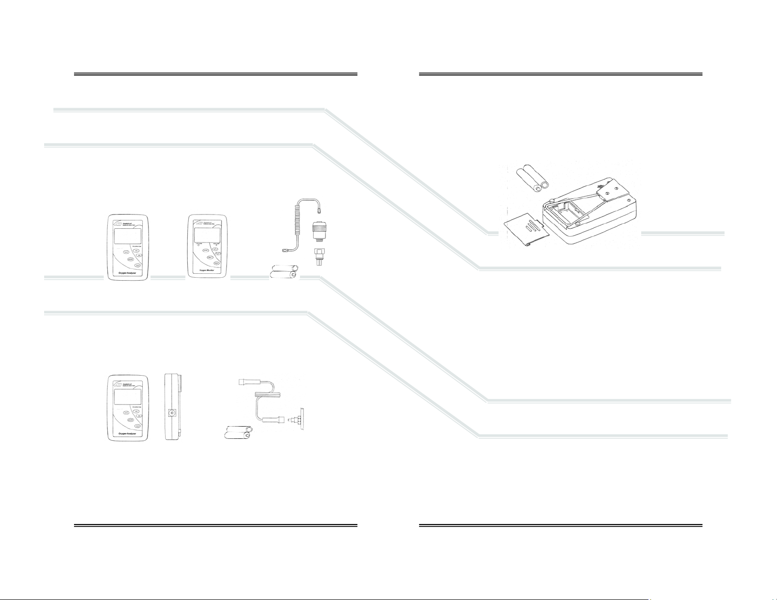
4 Start-Up
4.1 Contents of Shipp ing Container:
4.1.1 AII 2000 A Oxygen Analy zer, and AI I 2000 M Oxygen Monitor:
ENCL-1061 V-mount retainer (attached)
ENCL-1066 Tripod wire stand (attached)
AII-11-60 Oxygen Sensor
BATT-1008 Battery, AA 1.5V Alkaline (Qty 2)
CABL-1006 Cable, Coiled Phone Jack
FITN-1065 Flow diverter
P-1087 Instructions for Use
4.1.1 AII 2000 HC Oxygen Analyzer, Home Care:
ENCL-1061 V-mount retainer (attached)
ENCL-1066 Tripod wire stand (attached)
AII-11-60-HC Oxygen Sensor (installed inside analyzer)
BATT-1008 Battery, AA 1.5V Alkaline (Qty 2)
TUBE-1007 Tubing, 1/4” Tubing 7 ft. with Adapter
P-1087 Instructions for Use
Inspect t he box and cont ents for shippi ng damage. If t he device or
compone nts app ear dam age d, do not a ttem pt to oper ate t he devi ce -
contact the manufacturer immediately, refer to section 9.
OR
AND
AND
4.2 Install Batteries
All devices are powered by two 1.5V AA alkaline batteries which must be installed before the device can be operated.
The battery compartment is located at the rear of all devices. Initially
this proc edure c an be som ewhat dif ficult. C are sho uld be take n not to
damage the case when removing the battery compartment cover.
4.2.1 Procedure:
1. Remove the device and the (2) AA 1.5V Alkaline batteries from the foam
shipping container.
2. Turn t he devi ce over so the s hortest r aised line on the batt ery co mpartment cover is pointing away from you.
3. Lift the tripod wire stand up and away from the case.
4. Grasp the c ase wit h both hands, use y our thum bs pres s dow n firm ly on
the raised lines and push the battery compartment cover away from you.
5. Locate the positive (+) and negative (-) terminals on the battery.
6. Assure the battery contacts are clean.
7. Ali gn one batt ery’s posi tive (+) termin al with t he corr espondin g (+) battery sy mbo l m o lded into the case.
8. Insert the battery into the compartment.
9. Repeat with the remaining battery.
10. Replace the battery comp artment cover, make sure it snaps into p osition
and is secured flush against the case. Replace the wire stand as required.
Replac e the bat teri es w ithi n tw e nty- four (24) ho ur s of the b att ery sym bol appearing on LCD display because batteries decline at different
rates. Calibrate the dev ice after repla cing the batteries.
8
9
Page 7

4.3 Install Oxygen Sensor
The device cannot function until the oxygen sensor is installed. Once installed,
allow the sensor to stabilize for 15-20 minutes in ambient air before attempting to calibr ate the device.
NEVER - Attempt to open, repair or service the oxygen sensor.
Refer to Sect ion 3 f or hi nts an d war nin gs co ncer nin g th e han dli ng an d
environmental considerations of the oxygen sensor and the device.
4.3.1 AII 2000 A Oxygen Analyzer, AII-2000 M Oxyge n M onitor:
1. Remov e the content s fro m the shipping co ntainer as sho wn in s ection 4.1
and check for damage.
2. The coiled cable uses a common RJ11 phone jack at both ends, making a
bad connection impossible.
3. Inst all the sensor awa y from any humidifyin g device to pr event moi sture
from condensing on the sensing surface and assure accurate calibration
and oxygen readings.
4. Connect one end of the cable to the device in the same manner you
would co nnect a telepho n e. Si m pl y f ind and regis t er the male pl ug at th e
end of the coiled cable and insert it into the mating female jack on the
side of the device.
5. Connect the other end of the cable to the sensor in the same manner.
6. For diffusion sampling of static, ambient or controlled atmospheres –
incubators, infant hoods, tents, etc., the flow diverter and tee are not
required as shown above.
7. For sampli ng breathing ci rcuits with f lowing gas, use the flow di verter
and tee adapter accessories supplied with the device, and, position the
sensor vertically for optimum results, as shown right. The flow div erter
avoids stagnation and facilitates the movement of gas to and from the
sensing ar ea of t he s ens or th ereby pro du cing a mor e accur ate me a surement of the gas stream to be measured.
8. Install the tee-a dapter in the breathin g circuit.
9. Screw the flow diverter to the sensor.
10. Ensure the o-ring is lightly lubricated for ease of entry and a tight seal
between the flow diverter and tee adapter.
11. Insert the assembled flow diverter/sensor into the tee allowing 100%
oxygen ( dry, no n-hum idif ied) to f low pas t th e sens or at a r ate les s tha n
10 liters per minute.
4.3.2 AII 2000 HC Oxygen Analyzer:
When the Home Care version with its integral oxygen sensor is ordered, the
device is shipped with the sensor installe d.
4.4 Controls
4.4.1 AII 2000 A and AII 2000 HC Oxyge n Ana lyzers
These analyzers employ a micro-processor that is controlled by five (5)
pushbuttons located on the keypad attached to front cover.
1. ON/OFF provides power to the electronics
2. ESCAPE abo r ts a previous sele cted option
3. ENTER selec ts a me nu opti o n
4. 100% initi ates t he routine for CA LIBRATI ON with 100 % oxygen. T he sensor must be exposed to 100% oxygen.
5. 21% initiates the routine for CALIBRATION with air or 21% oxygen. The
sensor must be exposed to air or 21% oxygen.
4.4.2 AII 2000 M Oxygen Monit or
The mo nitor emplo ys a menu driven micro -proces sor that i s cont roll ed by f ive
(5) pushbuttons located on the keypad attached to front cover.
1. ON/OFF provides power to the electronics
2. MENU accesses the MAIN MENU
3. ENTER s elects a menu o p ti o n, and, en abl es the us er t o s i l ence th e a udi bl e
alarm qu ickly without ha ving to navigate through th e menu (s)
4. DOWN ARROW scrolls down the menu options
5. UP ARROW scrolls up the menu op tions
Note: The monitor is equipped with visual and audible HIGH and LOW
(minimum set point of 15%) alarms which are controlled through the MAIN
MENU a nd are activat ed when the ox ygen val ue is 0. 1% bel ow the LO alarm
set point or 0.1% above the HI alarm set point, refer to section 4.6 below.
4.4.3 Instructions and Warnings displayed by LCD
START-UP TEST – diagnostic tests of the electronics, alarm circuit
(monitors only), battery voltage and the sensor’s signal output.
SERVICE DEVICE – non-sensor failures during the start-up test.
CHECK SAMPLE GAS, CHECK CA BLE, CHECK SENSOR – se nsor fails the
start-up test or becomes disconnected during operation, or if an alarms is
activated (monitor).
SAMPLING – oxygen concentration from 0-100% in the sample gas during
the normal operation.
BAT LOW – battery voltage is not adequate, replace batteries.
ALARM SET POINTS, CONDITION (set point reverses color and red LED
indicator turns on) for monitor only.
10
11
Page 8

4.5 Start-Up Test
Press the ON/OFF key o n the front panel to apply power to th e device and
initiate a complete diagnostic test of all system functions: the electronics,
feeds voltage and tests the alarm circuit (monitor only below right) internally,
confirms the battery voltage is ad equate to power the circuit, and, the sensor’s signal output is with in specificatio ns.
START-UP TEST
ELECTRONICS - PASS
ALARMS - N/A
BATTERY - PASS
SENSOR - PASS
Following successful Start-Up Test the devices default to the SAMPLING mode.
20.9 %
SAMPLING
With t he excepti on of th e ALARM S for th e AII-20 00 M (a bove lef t) the t ests
and result ing displays are t he same.
Note: Any START-UP TEST failure requires the user to take corrective
action before continuing or attempting to use any device.
4.5.1 Electronics, Alarms (AII-2000 M Monitor) or Batt e ry Failure
If any of these START-UP TESTs ar e unsuccessf ul, the follow ing display instructs th e user to SE RVIC E DEVIC E. The f oll owing di splay is the same f or all
models.
ELECTRONICS - FAILED
SENSOR - FAILED LOW
20.9 %
LO 15% HI 50%
START-UP TEST
ALARMS - FAILED
BATTERY - FAILED
SERVICE DEVICE
START-UP TEST
ELECTRONICS - PASS
ALARMS - PASS
BATTERY - PASS
SENSOR - PASS
SAMPLING
4.5.2 Sensor Failure
Sensor failure can result from multiple causes; the user’s failure to connect a
sensor or sensor cable, a defectiv e sensor cable or a se nsor with an output
outside specificatio n.
SENSOR - FAILED LOW is one of the po ss ible unsuccess ful START-UP TEST s as
illustrated previously and displays additiona l warnings as follows.
4.5.2.1 AII 2000 A and AII 2000 HC Ox yg e n A nalyzers
The LCD alternately d is plays the followin g until the problem is corrected.
Corrective action:
1. Expose the sensor to air or a gas containing approximately 20.9% oxygen
2. Connect or replace the cable connecting the sensor to the analyzer
3. Connect or replace the oxygen sensor
4.5.2.2 AII 2000 M Oxygen M onitor
Performs th e sam e rou ti ne an d requi r es th e sam e cor rect iv e acti on as th e analyzers above with additional indicators related to the monitor’s alarm feature.
In addition to the alternating LCD display, the LO ALARM becomes active and:
0.0 %
ALARM
0.0 %
ALARM
LO 15% HI 50%
CHECK SAMP LE GAS
CHECK SAMP LE GAS
LO 15% HI 50%
CHECK CABLE
CHECK SEN SO R
ALARM
CHECK CABLE
CHECK SEN SO R
ALARM
LO ALARM value and background alternately reverse colors on the LCD
RED LED bel o w th e LO ALARM valu e li ghts up a nd be gi ns fl as hing
Audible alarm begins beeping
The audible alarm can be disabled for two (2) minutes (unlimited times) by:
1. Press the MENU key on the fr ont panel
2. Press the UP/DOWN arrow to select ALARMS AUDIBLE
3. Press the ENTER key to toggle to ALARMS SILENT mode
12
13
Page 9

4.6 Alarms AII 2000M Oxyge n M onitor
The monitor is equipped with user selectable HI and LO alarm set points
which are displayed at th e bottom of the LCD. The default alarm set points
are 15% LO an d 50% HI. The L O alarm set point c an be set between 15 %
and 99% and the HI alarm set point can be set between 16% and 100%.
Alarm set points may be adj usted in 1% i ncrements by pressing a nd holding
the UP/ D OWN A R ROW keys, see below . T he A RROW k e ys are dis abl ed wh en
the alarm set points are within 1% of e ach ot her to pre vent th e HI a larm f rom
being set below th e LO alarm. T h e HI alarm may be di s abl e d by atte m pti ng t o
select a HI alarm set point above 100% to facilitate flushing patients after
anesthe s ia. In this mode the LCD continually displays HI OFF.
The AII-2000 M Oxygen Monitor i s equipped with four (4) indicators that activate wh en oxyge n concent rations are 0.1% below the LO alarm s et poi nt or
0.1% above the HI alarm set point.
1. LCD alternates b etween the ALAR M mode with an oxyge n reading 0.0%
and reco mm endation as illustrated in sec tions 4.5.2.1 and 4.5.2.2
2. Alarm value and background alternately reverse color on LCD
3. Red LED below the alarm value lights up and begins flashing
4. Audible alarm begins beeping
4.6.1 Setting Alarm Set Points
1. Fr om the SA MPLING mode pres s MENU
to display the MAIN MENU
2. Press the UP/DOWN arrow keys to
highlight SET ALARMS
3. Press ENTER to select SET ALARMS
4. LO alarm value is highlighted by default
5. Press ENTER to skip the LO alarm (and
proceed to t he HI alarm) or pres s the
UP/DOWN arrow keys to change the
alarm set point
6. Press ENTER to save LO alarm set point
and move to select the HI alarm
7. Pres s ENTE R to s kip t he HI al arm ( and
return to SAMPLING mode) or press the
UP/DOWN arrow keys to change the
alarm set point
8. Press ENTER to save HI alarm set point
and return to SAMPLING mode
9. If no key is pressed within 5 seconds,
the LCD returns to the SAMPLING mode
20.9 %
SAMPLING
LO 15% HI 50%
MAIN MENU
CALIBRATE
SET ALARMS
ALARMS AUDI BL E
LO 15% HI 50%
SET LOW/HIGH ALARM
USE UP/DOWN ARROWS
TO ADJUST VALUE
TO SKIP - PRESS ENTER
LO 15% HI 50%
4.7 Calibration
Electro chem ical oxy ge n sens ors ge ner at e sli ghtl y di ff erent sign al o utput s under
identical conditions due to variations in the thickness of the sensing membrane
and manufacturing p r ocess.
Simulate the application for optimum accuracy: Review Sections 3
Safety Warnings and 5.2 Application Considerations before proceeding.
The de vices are d esigned to meet th e requireme nts for bo th ambi ent
and el evated oxyge n measurements b ut should NEVER be calibrated
with air or 21% oxygen with the intent of taking oxygen measur ements
at oxygen levels a bove 30% oxygen.
Accordin gly, the d evices may be calibr ated with ei ther air (20.9%) or
100% oxygen which req uires the user to m ake a conscious de cision to
bypass or skip the recommended 100% oxygen calibration.
Set-Up:
AII-2000 A and AII-2000 M refer to section 5.4.1 Flowing Gas
Streams or 5.4.2 Static Atmospheres.
AII-2000 HC refer to section 5.4.3.
14
15
Page 10

Procedure
AII 2000 Seri es A nal yzers an d Mo nito r em ploy t he i de ntical c ali brati on r outi ne
and displays but they differ slightly in the way they arrive at the display that
initiates calibration routine. Refer to Set-Up illustration and references above
for gas connections.
1. AII-2000 A and AII-2000 HC Oxygen Analyzers - Press the 21% key under
the word CALIBRATION on the front panel.
1a. AII-2000 M Oxygen Monitor - Requires navigating its menu to reach the
display that initiates the calibra t io n routine.
a. From the SAMPLING menu, press
MENU to display the MAIN MENU
b. Press the UP/DOWN arrow keys to
highlight CALIBRATE
c. Press ENTER to select CALIBRATE (the
four (4) alarm indicators are disabled
during the calibration routine)
Both of the above produce the following display which initiates th e
calibration routine.
3. The above pr o mpt re mains on the display until:
a. The operator presses ENTER to proceed or
b. The ESCAPE key on the AII-2000 A and AII-2000 HC or the MENU key
on the AII-2000 M to abort and return to the SAMPLING mode.
4. Expose the sensor to a known source of fresh ambient air or certified 21%
(dry, non-humidifie d) oxygen ni trogen m ix but not the oxygen enriched
room air commonly found in hospitals.
5. Once a suitable calibra t ion gas is intro-
duced, press ENTER to initiate calib r ation
as displayed right and disable the key
pad (to prevent the calibra tion rout i ne
from being interrupted).
6. This display appears for sixty (60) seconds
to allow the sensor to s ta bilize before
the microprocessor takes the final reading.
20.9 %
INTRODUCE AIR/21% OXYGEN
OBSERVE TREND
PRESS ENTER TO CAL
16
LO 15% HI 50%
MAIN MENU
CALIBRATE
SET ALARMS
ALARMS AUDI BL E
20.9 %
AIR CALIBRATION
IN PROCESS
7. If the calibration is su ccessful, the display below left appears for
three (3) seconds before defaulting to the display below right:
20.9 %
8. The display above right requires a decision by the user (refer to
warnings at the beginning of section 4.7) to press ENTER and
skip the 100% O2 calibration and return to the SAMPLING mode;
or, wait ten (10) se conds for the followin g display:
9. Repeat steps #3 through #6 using a certified source of 100% oxygen.
10. If the calibration is successful, the display
at right appears for five (5) seconds before
defaulting to the SAMPLING mode.
Calibration Fails
An unsuccessful calibration can be caused by
several problems as displayed at right:
If after three (3) unsuccessful attempts to
calibrate: review section 7 for pos sible causes
and corr ective acti on or contact Analytical Industries Inc. at 909-392-6900.
To abort the RETRY press ESCAPE (analyzer) or MENU (monitor). Do
not proceed until the analyzer is calibra tion successfully.
AIR CALIBRATION
SUCCESSFUL
20.9 %
INTRODUCE 100% O2
OBSERVE TREND
PRESS ENTER TO CAL
17
TO SKIP 100% O2 CAL
PRESS ENTER
FOR 100% O2 CAL
WAIT FOR NEXT
DISPLAY
100 %
OXYGEN CALIBRATION
SUCCESSFUL
AIR / 100% O2 CALIBRATION
FAILED
- CHECK CAL GAS
- CHECK CABLE
- CHECK SENSOR
RETRY - PRESS ENTER
Page 11

4.8 Mounting
Every analyzer and monitor is equipped with a male dove tail bracket and
triangular shaped thick metal wire stan d secured to the rear o f the enclosure.
Tripod W i re Stand
Secured b etwe en b ump er f eet o n eith er s id e of t he b atter y com part ment i s a
triangular shaped thick metal wire stand that is hinged under the dove tail
bracket secured at the opposite end of enclosure.
Unsnap the triangular thick metal wire stand from between the bumper feet
and pull it away from the enclos ure to form a tripod which allows the devi ce to
sit upright on any flat surface
Dove Tail Bracket
The male dove t ail bracket is s ecured to the rear of the enclosure with two
screws. The 1” female dove tail pole bracket (HRWR-1075) is an optional accessory that is commonly found in medical applications. The v-shaped male
componen t simply slides into and out of the po le mou nted female section.
5 Operation
5.1 Principle of Operation
The AII 2000 Series O xygen Analyzers and Monitor u tilize an electrochemical
galvanic f uel cell type ox ygen sensor of the type t hat is exte nsively used to
measure oxygen concentrations from 0% to 100% in gas streams. Oxygen, the
fuel fo r this electr o chemi cal t rans du cer, di ff using i nto t he se nso r t hro ugh a gas
permeabl e mem br ane r e acts c hem ical ly at t he s ensin g electro de to prod uce an
electrical current output proportional to t he oxygen concentration in the gas
phase. The sensor has an absolute zero meaning that when no oxygen is present to be chemically reac te d the LCD displays 00. 0 oxygen.
The sens o r’ s s i gnal o utput i s l i near over the e nti r e rang e, remains vir t ual l y co n stant over th e speci f i ed useful life and dr ops of f s h ar ply at the end. Th e sensor
itself re quires no maintenance and is simply replaced at the end of its u s eful life
like a battery. Inasmuch as the sensor is a transducer in its own right, its expected life is not affected by whether the analyzer is ON or OFF.
The relationship between the sensor’s signal and changes with the oxygen
concentration is both proportional and linear, thus allowing single point calibration. Ot her factors that c an affect the si gn al output are describe d i n Section 5.2
Application Considerations and Section 3 Safety Warnings which should be read
before use.
Historic ally, the expect ed life of galvanic fue l type sensors has been spe cified as
“in air (20.9% O
type s ens or i s inv ersel y aff ect ed b y c ha nges i n t he aver ag e o xyg en conc e ntration, t em p er ature and pr es s ure it i s exposed t o duri n g its useful l i f e. For ex am ple, the AII-11-60 sensor has a 60 mo nths e xpected life in air (20.9 % oxygen)
at 25°C a nd ambient pres sure, howe ver, in a 100 % oxygen atmo sphere the
expected life is 12.6 months [60mo/(100%/20.9%)].
AII 2000 Seri es Oxyg en Anal yzer s and M onit ors are batt er y pow ere d b y (2) AA
alkaline batteries and controlled by a state-of-the-art micro processor. The batteries p rovid e eno ugh pow er to oper ate th e anal yzer co ntin uously for ap proximately 1,200 hours. Both devices utilize a membrane type keypad for users to
communicate commands to the microprocessor. The monitor is menu driven to
accommo date th e alar m f uncti o ns. Th e digit al el ectr oni cs pro vid e fe atur es suc h
as system diagnostics, warning indicators, controls and an alarm capability for
continuo us mo nitori ng tha t en hance bo th s afet y and ef fecti veness. The d esign
criteria, quality program and performance features ensure reliable and accurate
oxygen measurements.
) at 25°C and 760mm Hg”. The actual life of any galvanic fuel
2
18
19
Page 12

5.2 Application Consideratio ns
Effect of Anesthetic Agents
The AII 2000 Series Oxygen Analyzers and Monitors utilize an electrochemical
galvanic fuel cell type sensor, model AII-11-60, that has been characterized by
its gas permeable sensing membrane that allows the gas to be analyzed to
diffus e into the sensor w here oxyg en can be reacted. The dis played oxyg en
concentr atio n of al l s ensors of t his d esign d ecreas es i n th e pres ence o f a nesthesia gases. EN 1259 8:1999/I SO 776 7:1997 ( E) establ ished sta ndards f or the
maximum error allow able over a given durati on. Th e anesth etic a gents l isted
(Halothane, Enflurane, Isoflurane, Sevoflurane and Desflurance) were vaporized into a gas stream of 30% oxygen / 70% nitrous oxide.
Gas Test Level Decrease in O
Helium 50%, Balance O
Nitrous Oxide 80%, Balance O
Carbon Dioxide 10%, Balance O
0%
2
0%
2
0%
2
Reading
2
Halothane 4% <-1.5%
Enflurane 5% <-1.5%
Isoflurane 5% <-1.5%
Sevoflurane 5% <-1.5%
Desflurane 15% <-1.5%
The errors listed were observed after a two (2) hour exposure period. The
table above summ arizes the performance of the AII 2000 Series electronics
and AII- 11 -60 Oxygen Sensor. The above p er f o rm ances al l m eet or exc eed the
requirements established by EN 12598:1999/ISO 7767:1997 (E).
Do not operate any device in the presence of flammable anesthetic
agents such as Diethal Ether or Cyclpropane.
Note: The AII-11-60 Oxygen Sensor has been specifically designed and tested
to be compatible with nitrous o xide. For optimum results, mount the oxyge n
sensor w ith the s ensing ar ea facin g down tow ard the fl oor and be flushed or
calibrated with 100% oxygen every eight (8) hours.
Effect of Temperature
All mem bra ne clad electro ch emi cal se nsor s are t emp erat ur e depe ndent d ue t o
the expa ns i o n and contr a c ti o n of the Tef l o n sensin g m embrane. A s result m or e
or less of the sample gas including oxygen to be reacted diffuses into the sensor. The oxygen s ensor’s electrical current signal output varies linearly with
oxygen concen tr ati o n . T he s i gnal also var i es w i t h changes in ambi ent temp erature. The temperature coefficient is typically 2.54% of the signal or reading per
degree C change in temperature.
The tem perature de pendent c urrent sig nal output i s compensat ed by us ing a
resistor-thermistor network. With a proper resistor-thermistor network, the
signal can be compensated to within +
5% of the oxyg en reading over the 545°C temperature range. This is the worse case situation when going from one
extreme of the operating temperature range to the other. The error will be
elimi nated wh en th e therm istor in th e temper at ure comp ensat ion n etwor k and
the electrolyte inside the sensor reach thermal equilibrium in approximately 4560 minutes.
Erroneous oxygen readings can result if the gases flowing over the
sensing area o f th e se nso r ar e no t at am bie nt t emper at ure. This oc cur s
because t he sensor i s exposed to different tem peratur es. The sens ing
area of t he se nso r is o-ri ng se aled i n th e hea ted bre athi ng ci rcuit an d the t emperature compensation network at the rear of the s ensor is e xpos ed to ambie nt
temperature.
Effect of Pressure
Electrochemical sensors actually measure the partial pressure, not the percentage, of oxygen in the gas stream they are exposed to. These sensors are accurate at a ny pressure pro vided the press ure is consta nt and the analyzer h as
been calibrated at the same pressure as the sample gas measured.
For exam ple, when connect ed to a ve ntilator circ uit, the si x (6) second T90
respons e time of the AI I-11-60 Oxygen S ensor ca uses th e analyz er to dis play
an increase in the oxygen reading displayed when in fact the alternating
breathing pressure cycles generated by the ventilator is increasing the total
pressure.
The increase in the reading displayed is not related to a change in the oxygen
percentage but to the increase in partial pressure (corresponding to the increase in total pressure).
Calibrat e at the tem perat ure and press ure (alti tude) at which th e ana-
lyzer will be operated.
Effect of Humidity
The an alyzer is no t affect ed by non -condensin g relativ e humidit y (RH). Ho wever, the use of a humidifier to introduce water vapor and increase the moisture level of the gas mixture does affect the oxygen concentration and the
resultant reading dis played by the anal yzer. The addi tion of wate r vapor increases the total pr es s ure ther eby dil ut i ng o r decreasi ng the o xygen co nc entration of the ga s m ixture resulting in a lower oxygen r eading.
20
21
Page 13

Calibrate at the temperature and pressure (altitude) at which the analyzer will b e operated, hum idified gases cannot be 100% oxygen.
Effect of Condens ation
Excessiv e co ndens at ion c oll ecting on t he s ensi ng ar ea or th e el ectri cal con nections at th e rear o f t he s ensor s can adve rs ely i m pact t he per for man ce of el ectrochemical sensors. Cond e nsation bl ocks the diffusion p ath of oxygen into the
sensor an d can r educe the ox ygen r eading t o 00.0 i f the cond ensat ion covers
the entire sensing area. Condensation on the electrical connections at the rear
of the s ensor can aff ect ox ygen re adings . R emedy either situ ation by sh aking
out the condensation and allowing the sensor to air dry.
Erroneously characterized in many instances as a sensor failure, excessive
condensation is rem edied by gently wi ping away the condensation with a soft
cloth or simply allowing the sensor to air dry.
Effect of Electromagnetic Radiation
Tested o ver a 26 MHz t o 1000 MHz ele ctrom agneti c fiel d, the a nalyz er is s usceptibl e at al l frequencies tes ted except tho se betw ee n 93 0 and 990 MHz.
Never o perate the a nalyzer near equipment c apable of emi tting hig h
levels of electromagnetic radiation. Do not continue to operate the
analyzer if the reading becomes unstable.
Calibration
Calibrating t he analyz er or moni tor durin g normal o peration invol ves
the same pr ecautions a nd proc edures as thos e described in S ections
4.7 Start-up Calibration with t he same cautions to review Sections 3
Safety Warn ings and 5.2 Applic ation Conside ra t io ns.
5.4 Sampling
Assuming the START-UP instructions are followed and the tests are completed
successfully the devices de fault t o the SAMPLIN G mode.
Never ope r ate the analyzer if the r eading is unstab le o r if a ma lfunction
is suspected. If calibration is required as indicated herein, do not proceed until the analyzer is calibration succ essfully.
5.4.1 Flowing Gas Stream s (B re a thing Circuits)
1. Place the sensi ng are a of the s ensor i nto the g as stream to be analyzed
upstream of any humidification equipment.
2. Assure that the flow rate of the gas stream does not exceed ten (10) liters
per minute. Exceeding ten (10) liters per minute generates backpressure.
3. Check the gas stream and particularly the mechanical connection for leaks
that dilute the gas stream with ambient ai r.
4. Assure there are no restrictions in the circuit downstream of the sensor
that could generate backpressure on the sensor.
5. Use th e f l o w di ver ter supplied wi th the d e vi ce along
with the optional tee adap ter and position the s ensor vertically for optimum results, as shown right.
The flow diverter avoids stagnation and facilitates
the movement of gas to and from the sensing area
of the sensor thereby producing a more accurate
measurement of the gas stream to be measured.
6. Install the tee-a dapter in the breathin g circuit.
7. Screw the flow diverter to the sensor.
8. Ensure the o-ring is lightly lubricated for ease of
entry and a tight seal between the flow diverter and
tee adapter.
9. Insert the assembled flow diverter/sensor into the tee allowing 100%
oxygen (dry, non-humidi fi ed) to f low past t he se nsor at a r ate of 5-8 l i ters
per minute.
10. Once th e sensin g area of the se nsor is expose d to the gas stre am all ow
approximately sixty (60) seconds for the reading to stabilize and observe
the reading displayed by the LCD.
5.4.2 Static Atmospheres (Incubators, Hoods, Oxyge n Tents)
Remove the flow diverter, not needed. Failure to remove the flow diverter will
dramatically slow the response time of the sensor.
Expose the sensing area of the sensor to the atmosphere allowing approximately sixty (60) seconds for the reading to stabilize and observe the reading
displayed by the LCD.
If placing the entire sensor inside the controlled atmosphere review
Section 5.2 Applicat ion C on s ideration, Effe ct of Temperature.
22
23
Page 14

5.4.3 AII 2000HC Oxygen Analyzer (Integral Oxygen Sensor)
AII 2000HC w ith its integr al oxy gen sensor req uires co nnecting the ¼” tu bing
supplied (section 4.2.1 abo ve) with th e d evice to a ¼” hose bar b attached to a
pressure regulator controlling a source of gas flowing at less than 10 liters per
minute.
5.5 Alarms (AII 2000M Oxyge n M onito r):
The mo ni to r i s eq ui pped w i th us er select able HI a nd LO alarm se t points w hi ch
are displayed at the bottom of the LCD. Section 4.6 describes the operation
and procedure for setting the alarms in detail.
6 Maintenance
Review Section 3 Safety Warnings and Section 7 Troubleshooting for
guidelin es on servicing the dev ices.
6.1 Serviceability
Do not op en t h e m ain com partm en t of t he anal yz er, as it cont ai ns no s er vic eable parts inside. Never attempt to repair the analyzer or sensor by yourself as
you may damage the analyzer which could void the warranty.
6.1.2 Cleaning / Reuse Instructions
Clean th e devic e, oxyge n sens or and accessori es with a soft cl oth dam pened
with either water or mild isopropyl alcohol solution (70% isopropyl alcohol
solution in water), if necessary, before re-use. Allow the components to air-dry
after cleaning.
Note: The Home Care Kit is not intended for patient use, it is intended solely
for conf irming t he O
cleaning instructions apply.
6.2 Battery Replacement
The an alyzers an d monit or are po wered b y two A A alkali ne batt eries wi th an
approximate life of 1,200 hours. A low b attery indicator circ uit monitors th e
battery suppl y vol t a ge and s en ds a si gn al di rectly t o the LCD when the bat t er y
voltage reaches a preset level that activates the battery symbol in the LCD.
The bat t eri es are housed in a s eparate co m p ar tment l o c at e d at t he rear o f the
device and are accessible by sliding the removable cover.
concentration in Oxygen Concentrators. Accordingly, no
2
Initially this procedure can be somewhat difficult. Care should be taken
not to damage the case when removing the battery compartment cover.
6.2.1 Procedure:
1. Turn the device over so the
shortest raised l ine o n t he battery
compartment cover is pointing
away from you.
2. Lift the tripod wire stand up and
away from the case.
3. Grasp the case with both hands
and using your thumbs press
down fir mly on the rai sed li nes and push t he battery compart ment cover
away from you.
4. Locate the positive (+) and negative (-) terminals on the battery.
5. Assure the battery contacts are clean.
6. Ali gn one batt ery’s posi tive (+) termin al with t he corr espondin g (+) bat-
tery sy mbo l m o lded into the case.
7. Insert the battery into the compartment.
8. Repeat with the remaining battery.
9. Replace the batter y compartment cover, make sure it snaps into position
and is secured flush against the case. Replace the wire stand as required.
10. Calibrate the device after replacing the batteries.
6.3 Oxygen Sensor Replacement
The desi gn of th e electr onics is int ended f or only t he An alytical Indus tries I nc.
AII-11-60 or AI I-11-60-HC Oxygen Sensors. Use of a different o xygen sensor
may result in an erroneous oxygen reading.
NEVER - Open th e oxygen s ensor or probe t he sensin g surfac e, refer
to Section 10 in the event the sensor should leak and someone comes
in contact with the electrolyte from inside the sensor.
6.3.1 Procedure AII 2000 M and A II 2000A - External Sensor
1. Disconnect the cable from the old sensor just as you disconnect a tele-
phone jack from a wall plug.
2. To connect the new sensor simply fi nd and register the male plug at the
end of the coiled cable and insert it into the mating female jack at the rear
of the senso r unt il it mates or snaps into place.
3. Calibrate the device after replacing the oxygen sensor.
24
25
Page 15

6.3.2 Procedure AII 2000 HC - Integ ral Se nsor
1. Tools required: small bladed screwdriver.
2. Plac e the device face down on a flat surface.
3. Remove the two (2) screws from the upper corners of the rear of the
device.
4. Move the tri pod up, rem ove the batt ery compartment co ver (see B attery
Replacement) and remove the two (2) screws located on either side.
5. Pull the rear section up ¼”-½”, turn it over and lay it next to the other
section.
6. Loc ate the w hite co nnecto r at the e nd of the f our (4) wires runnin g fro m
the sensor (the cylinder with the white label) to the top of the PCB.
7. With your left for finger and thumb, grasp the sides of the back end of the
white connector where it is soldered to the PCB.
8. With yo ur rig ht fore f inger and thumb, grasp t he sides of the sec tion of
the white connector where the four (4) wires from the sensor terminate.
9. Separate the connector - hold the white connector section your left hand
while gently pulling and wiggling the white connector section with your
right hand until it unlo cks.
10. The oxygen sensor inserts into an adaptor (identified by a round recess
with a cylindrical hose adapter in the center) that slides into grooves
molded into the side of the case .
11. Hold the r ear section of the cas e down, gr asp the sq uare edges of the
adaptor, lift up (lift straight up so as not to strip the grooves molded into
the adaptor and case) and remove the adaptor and oxygen sensor as a
single component.
12. Once th e adapt er and ol d sensor h ave bee n removed f rom the c ase, ho ld
the label of the s ensor , agai n grasp t he s quare ed ges of the ada ptor and
pull – to separate the old sensor from the adaptor.
13. Remove the new oxygen sensor from the plastic shipping container.
14. Install the new oxygen sensor by reversing s teps 12 through 3.
15. Calibrate the device after replacing the oxygen sensor.
7 Troubleshooting
If the recom men ded corr ective a ction does no t resol ve the probl em retur n the
device to the factory for service.
Symptom Corrective Action
Device appears to be physically dam age d
No digital display when analyzer is turned ON
Battery symbol on LCD display
LCD display reads 00.0
No response to keypad command
Cannot turn device OFF
Turn device ON – if it successful passes
START-UP TEST and calibrates – proceed.
Install b attery
Replace bat tery
Check battery polarity
Check and/ or cl ean battery contacts
Replace battery and calibrate device
Install sensor
Check electric al connections
Assure el ec t ri c al connecti ons are dry
Replace bat tery
Calibration routine in process – escape or
wait until completed
26
27
Page 16

Symptom Corrective Action
Reading displayed by LCD
drifts during calibr ation
Analyzer reading climbs after
calibration in 100% dry oxygen when exposed to air
20.9%
After calibration in 100% dry
oxygen, analyzer reading
drifts more than 2% over 8
hours
Reading displayed by LCD
does not change when oxygen leve l cha nges
Reading does not stabilize or
fluctuates erratically
Wait 5 minutes and repeat calibration with
sensor placed on flat surface (not in your
hand)
Check integrity of gas delivery system
Check sensor’s front o-ring seal
Verify calibration gas in not humidified
Remove moisture covering sensor
Replace sensor, repeat calibration
Allow the sensor to stabilize for 5 minutes in
100% dry oxygen and recalibrate
Check p r im ary oxygen delivery device
Replac e sens or t ha t is near i ng th e e nd of its
useful life
Replace sensor
Relocat e analyz er aw ay sour ce of radio f requency or electromagnetic radiation emissions. Tested o ver a 26 MHz to 1000 MHz
electromagnet i c f i el d, the anal yz er i s s us c eptible at all frequencies tested except those
between 930 and 990 MHz.
Check sensor connection
Check cable connection
Wait 5 minu te s and repeat calib ration
Replace sensor, repeat calibration
Do not attempt to use the analyzer and
return the analyzer for service.
Symptom Corrective Action
Reading displayed by LCD
does not change when calibratio n control is adju s ted
Reading displayed by LCD is
very low
Alarms continuously activated
Replace sensor
Check sensor connection
Check cable connection
Replace sensor
None – Normal operation, confirm set points
Abnormal Adjust alarm set points
Remove moisture covering sensor
Check sensor connection
Check cable connection
Check integrity of gas delivery system
Check sensor’s front o-ring seal
Verify calibration gas in not humidified
Verify flow rate is 4-5 liters per minute
Replace sensor
Replace cable
28
29
Page 17

8 Specifications
Accuracy: +
Analysis: 0-100% oxygen
Area Classification: Ge nera l purpose
Alarms:
Calibration: 100% oxygen before using each day or aft er 8 hours of
Compensation: Temperature compensated
Connections: (M, A) 1x16mm thread or o-ring diverter; (HC) tubing
Controls: Soft touch keypad for ON/OFF and menu function
Dimensions: 3.6 x 5.9 x 1.6”; weight 10 oz. (280 grams)
Display: 3-1/2 digit backlit LCD 2.5” x 1.5”; resolution 0.1% O
Flow Sen sitivity: None between 0.2 to 10 liters per minut e
Humidity: Non-condensing 0-95% RH
LED Indicators: Analyzer - none; Monitor - upon activation of alarms
Linearity: +
Pressure: In let – (M, A) a mbient, (HC) regulate; v ent - atmo spheric
Power: 2 AA Alkaline batter i es ; 1, 20 0 hours co n t i nuous use
Respon se Time: 90% of final FS read ing in 9 seconds
Sensitivity: < 0.5% of FS range
Sensor: (M, A) AII-11-60 or (HC) AII-11-60-HC
Expected Life: 60 months in air at 25ºC and 1 atmosphere
Storage Temp.: -20º to 60ºC (-4ºF to 140ºF) on intermittent basis
Temp. Range: 5º to 45ºC (41ºF to 113ºF)
Warm-up Time: None
Warranty: 24 months analyzer; 18 months sensor (any application)
2% of FS range under constant conditions
Analyz er – non e; Moni tor - U s er adjust abl e H I 1 6-10 0%,
LO 15-99 %, 120 seco nd alarm si lence, HI alarm defe at
for flushing patients with 100% O
2
contin uous use.
2
1% under constant conditions
Expected Sensor Life
Consider s t he ful l ra ng e of t he se nso r’s signal , exam ple 7- 13 mV. M os t medi cal
oxygen sensors are configured to meet the published, see opposite page, specification which distrib utes the overall sensor life as fo llo ws :
- 60 months Expected Service Life (915,420 oxygen % hours)
- 6 months Recommended Storage Life period (91,542 % oxygen hours)
- 2 months margin of error
Therefor e, the Recommend ed Storag e life p eriod should not be co nsidered a
perishabl e shelf life. Op erating at the spe cified par ameters of oxyg en concentration (air 20.9%), temperature (25⁰C/77⁰F) and pressure (1 atm/bar), the
sensor will o perate for appr o ximately 68 m onths whether in storage or in use.
The purpo se of the Storage Li fe period i s to ensur e the user derives th e Expected Life of 60 mo nths (915,420 % oxygen ho urs) and does not lose the
benefit of the warranty.
Warranty
The 18 month (274,626 % oxygen hours) w arranty period (b egins with shipment from the factory and is limit ed to the first claim submitted) is ba s ed on:
- 60 months Expected Service Life (915,420 % oxygen hours)
- Estimated exposure (24/7) to 60-70% oxygen concentration
- Marginal of error of 2 months
8.1 Spare Parts & Accessories
AII-2000 A, AII-2000 M
Spare Parts: Spare Parts:
AII-11-60 Oxygen Sensor A II-11-60-HC Oxygen Sensor
BATT-1008 Battery (2x) 1.5V AA BATT-1008 Battery (2x) 1.5V AA
P-1087 Instructions for Use P-1087 Instructions for Use
A--1162 PCB Assy Main A-1162 PCB Assy Main
CABL-1006 Coil Cable TUBE-1007 1/4” Tubing 7’
FITN-1112-1 Flow Diverter
AII-2000 HC
Optional Accessories : Optional Accessories :
FITN-1009 Tee Adapter FITN-1066 Nipple Universal
HRWR-1075 Dovetail Clamp H RWR-1074 Doveta il C lamp
CC-1072 Carrying Case CC-1072 Carrying Case
30
31
Page 18

9 Warranty
Coverage
Under nor mal o perati ng co nditions , th e anal yzer an d sens ors ar e war rante d to
be free of defects in materials and workm anship for the period s pecif ied in the
current published specification s . To make a warranty claim, you must retur n th e
item properly packaged and postage prepaid to:
Analytical Industries in their sole discretion shall determine the nature of the
defect. If the item is determined to be eligible for warranty we will repair it or,
at our option, replace it at no charge to you. If w e choose to r epair your item,
we may us e new or reco ndition ed repl acem ent par ts of t he same o r upgr aded
design. This is the only warranty we will give and it sets forth all our responsibilities, there are no other express or imp lied warranties.
The war ra nty begi ns w ith t he date of ship me nt f rom An alyti c al Indu stri es I nc.,
is limited to the first customer who submits a claim for a given serial number
which must be in place and readable to be eligible for warranty and will not
extend to more than one customer or beyond the warranty period under any
conditions.
Exclusions
This warranty does not cover normal wear and tear; corrosion; damage while in
transit; damage resulting from misuse or abuse; lack of proper maintenance;
unauthorized repair or modification of the analyzer; fire; flood; explosion or
other fa ilure to follow the Owner’s Manual.
Limitations
Analytical Industries Inc. shall not liable for losses or damages of any kind; loss
of use of the a nalyzer; i n ci dental or cons e quenti al l o ss es o r d am ages; dam a ges
resulting from alterations, misuse, abuse, lack of proper maintenance; unauthorized repair or modification of the analyzer.
Service
Contact us between 8:00am and 5:00pm PST Mon day thru Thursday or before
12:00pm on Friday. Trained technicians will assist you in diagnosing the problem and determ i ning the appropriate cours e of action.
Analytical Industries Inc.
2855 Metropolitan Place
Pomona, Ca 91767 USA
T: 909-392-6900, F: 909-392-3665
E: sales-medical@aii1.com
, W: www.aii1.com
10 Material Safety Data Sheet (MSDS)
Product name Electrochemic al Galvanic Fu el Cell Oxygen Sensor
Exposure Sealed device with protective coverings, normally no hazard
Ingredients Carcinogens - none; Potassium Hydroxide (KOH), Lead (Pb)
Properties
Flash Points Not applicable, non-flammable
React ivity Stable; avo i d st r o ng acids, emits fumes when heated
Health Hazard KOH entry via ingestion - harmful or fatal if swallowed;
Symptom s Eye con ta ct - burning sensat io n; skin contact - slick feeling
Protection Ventilation - none; eye - safety glasses; hands - gloves
Precautions Do not remove Teflon and PCB coverings; do not probe wi th
Action KOH
Leak
10.1 Disposal
Oxygen sensors and batteries should be disposed of in accordance with local
regulations for batteries.
Completely soluble in H
eye - corrosive, possible loss of vision;
skin con ta ct - corrosive, p o s s ible chemical burn.
Liquid inhalation is unlikely.
Lead - known to caus e bir th defect s , co ntact unl i kely
sharp objects; avoid contact with eyes, skin and clothing.
Use rubber gloves, safety glasses and H
surfaces repeatedly with liberal amounts of H
WEEE regulations prohibit electronic products including the Helium a nd enviro nmental s ensors fr om being placed in househol d
trash bins.
Electronic products should be disposed of in accordance with local
regulations.
2O; ev aporation simi lar to H2O
2O and flush all
2O
32
33
 Loading...