


Analog Microelectronics, Inc.
AME7700/AME7701/AME7702
nn
n General Description
nn
Preliminary
Switched Capacitor Voltage Doublers
nn
n Features
nn
The AME7700 series of economical, Charge-Pump
Converters efficiently double a +1.5V to +5.5V input to
+3.0V to +11V, with a working current exceeding 100mA.
Due to their simplicity, small size, and performance,
these CMOS converters have numerous applications.
For most cases, only (2) external capacitors are required, however, in some cases, a single capacitor is
acceptable. Minimum capacitance is obtained with the
AME7701, while the AME7700 offers the lowest standby current. The AME7702 has a Frequency-Select pin
for added flexibility. The input voltage can be tripled or
quadrupled by cascading 2 Charge-Pumps. A single
alkaline battery
With it’s low start-up voltage, a single alkaline battery
can be configured with (2) AME7700’s to quadruple the
voltage and produce 5V out. Alternately, with a 5V
source, (2) AME7700’s can be configured to triple the
voltage and produce 15V out.
nn
n Typical Connection
nn
AME 7700/7701
V
IN
DC
IN
C1
CP
CN
OUT
GND
C2
V
OUT
l Small packages: SOT-25, SOT-26
l +1.5V to +5.5V Input Range
l 60uA Quiescent Current ( AME7700)
l 99% Conversion Efficiency
l Output Current Exceeding 100mA
l User Selectable Frequency ( AME7702)
nn
n Applications
nn
l Cellular Phones
l Digital Cameras
l Battery Chargers
l High Tech Flashlights
l PDA ’ s - LCD displays
l Consumer Electronics
l Pagers
l Portable Electronics
nn
n Pin Configuration
nn
SOT-25 Top View SOT-26 T op View
5
4
6
45
AME7700
AME7702
AME7701
2
12
1: GND 4: IN 1: GND 4: IN
2: OUT 5: CP 2: CN 5: FC
3: CN 3: OUT 6: CP
3
1
3
1

Analog Microelectronics, Inc.
AME7700/AME7701/AME7702
nn
n Pin Description
nn
AME7700AEEV/ AME7701AEEV
Pin Designation Function
1 GND Ground (-Supply )
2 OUT Po wer O u tput
3 CN Capacit or (-)
4 IN Power Input
5 CP Capacit or (+ )
AME7702AEEY
Pin Designa tion Function
1 GND Ground (-Supply )
2 CN Capacit or(-)
3 OUT Po wer O u tput
4 IN Power Input
5 FC Frequency Control
6 CP Capacit or (+ )
Preliminary
Switch Capacitor Voltage Doublers
nn
n Order Information
nn
Part Number Pac kage Operating Temp.
AM E 7700A E E V SOT-25 -40
AME7701AEEV SOT- 25 -40
AME7702AEEY SOT- 26
O
C to +85OC
O
C to +85OC
O
-40
C to +85OC
2
Analog Microelectronics, Inc.
AME7700/AME7701/AME7702
nn
n Absolute Maximum Ratings
nn
Preliminary
Switched Capacitor Voltage Doublers
Parameter
Supply Volt age
ESD C lassification
nn
n Recommended Operating Conditions
nn
Parameter
Supp ly Voltage
Ambient Temperatur e Range
Ju ncti on Temperatu re
nn
n Thermal Information
nn
Maximum Unit
6V
B
Rating
1. 5 - 5.5 V
o
-40 to +85
-40 t o + 125
C
o
C
Parameter
Thermal Resistan ce (SOT-25,26)
Maximum Junction T emperature
Maximum Lea d Temperatur e ( 10 Sec)
Caution: St ress above t he listed absolute r ating may cause pe rmanent damage t o the device
Maximum Unit
250
150
300
o
C / W
o
C
o
C
3

Analog Microelectronics, Inc.
AME7700/AME7701/AME7702
El ectrical Specification
nnnn
Preliminary
Switch Capacitor Voltage Doublers
TA = 25 C, VIN = 5V unless otherwise noted,C1 = C2 = 3.3
TEST CONDI T I O NSPARAMETER SYMBOL
AME7700
No Load Curren t I
Supply V olt age Range V
Oscillator Frequency F
Output Resistance Ro
Volt age Conversion E fficiency V
Power Efficiency P
IN
OSC
EFF
EFF
IN
AME 7702 FC is LO
AME7701
AME 7702 FC is HI
R
L
AME7700
AME 7702 FC is LO
AME7701
AME 7702 FC is HI
AME7700
AME 7702 FC is LO
AME7701
AME 7702 FC is HI
No load
R
L
F
µµµµ
= 10 K
= 10 K
MIN TYP MAX
60 100
215 300
1.5 5.5 V
8.5 12 15.5
24.5 35 45.5
40 50
20 35
97 99 %
88 92 %
UNITS
ohms
A
µ
KHz
4
Analog Microelectronics, Inc.
AME7700/AME7701/AME7702
Preliminary
Switched Capacitor Voltage Doublers
35
30
25
20
15
10
5
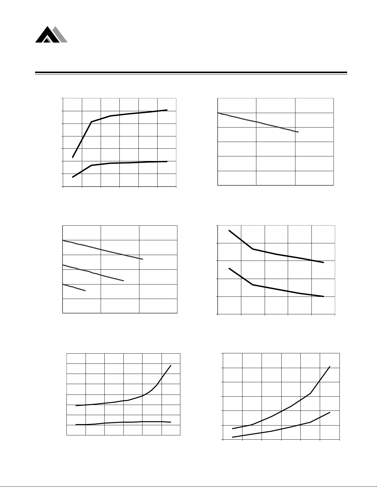
Oscillator Frequency (KHZ)
0
Osc. Freq. @ 25C
123456
Input Voltage (V)
Load Reg
12
10
Vin=5
8
Vin=3.3
V
6
OUT
4
2
Vin=2
AME7701
AME7700
AME7700
Load Regulation
12
10
8
6
OUT
V
4
2
0
050100150
I ( mA)
AME7700 Output Resistance @25C
50
45
40
35
30
Output Resistance (Ohm)
2.2µF
2.2µF
3.3
3.3
µ
F
µ
F
0
0 50 100 150
I(mA)
Electrical Characteristics vs. Temp
160
140
R
OUT
AME7700
AME7701
I
/
R
120
100
DD
OUT
80
60
40
20
0
25 50 75 100 125 150
I
DD
Temperature(0C)
25
23456
Supply Current @ 25C
300
250
200
150
100
Supply Current(mA)
50
0
123456
Input Vol t age (V )
Input Voltage (V)
AME7701
AME7701
AME7700
AME7700
5

Analog Microelectronics, Inc.
AME7700/AME7701/AME7702
nn
n Applications
nn
Single Cell Led Flashlight
- +
CN CP
AME
7700
IN
AA
1.5V
OUT
GND
Preliminary
Switch Capacitor Voltage Doublers
LED
1 Watt Fluorescent Lamp Driver
1 : 250
5v/200mA
IN
AME
CN
7701
1uF
GND
6
CCFL

Analog Microelectronics, Inc.
AME7700/AME7701/AME7702
nn
n Applications(Continued)
nn
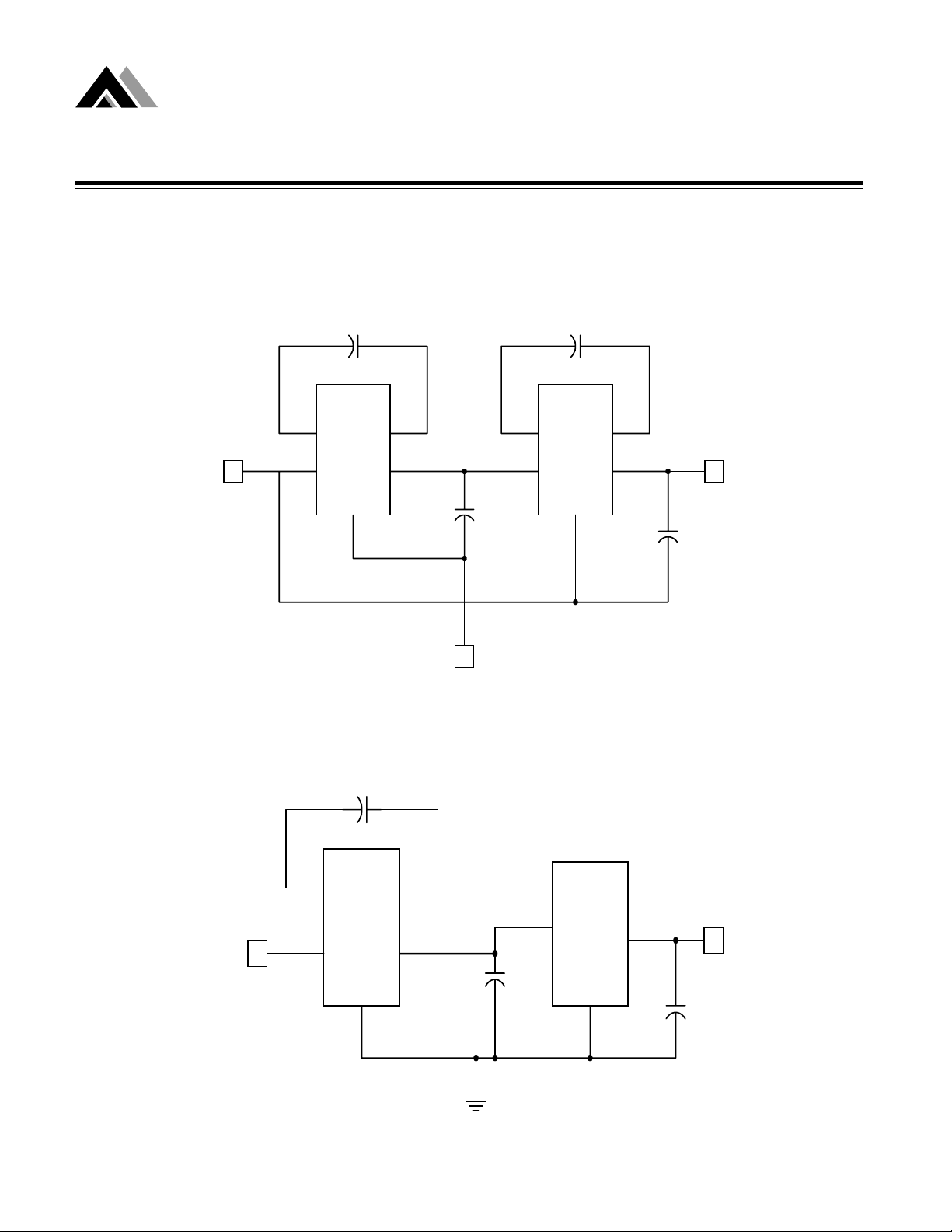
1.25V to 5.0V Converter
1uF 1uF
Switched Capacitor Voltage Doublers
Preliminary
1.25V
GND
- +
CN CP
AME
7701
IN OUT
GND GND
++
1uF 1uF
- +
CN CP
AME
7701
IN
OUT
5V
OUT
7
Analog Microelectronics, Inc.
AME7700/AME7701/AME7702
nn
n Applications(Continued)
nn
+5V to +15V Converter
10uF 10uF
Switch Capacitor Voltage Doublers
Preliminary
- +
AME
CN CP
7700
IN OU T
+5V
IN
3.3V-Input to Regulated 5V-Output
GND
(+10V)
+
10uF
GND
- +
AME
CN CP
7700
IN OUT
GND
Converter
+
+
10uF
+15V
OUT
1uF
CN CP
AME
3.3V
IN
8
7700
IN OUT
GND GND
1uF 1uF
+
IN
AME
8800
OUT
5V
OUT
+

Analog Microelectronics, Inc.
AME7700/AME7701/AME7702
nn
n Applications(Continued)
nn
Paralleling Devices
CN CP
Preliminary
Switched Capacitor Voltage Doublers
- +
3.3uF
AME
7701
V
IN
GND
- +
3.3uF
OUT
IN
CN CP
AME
7701
GND
OUT
IN
3.3uF
+
V
OUT
9

Analog Microelectronics, Inc.
AME7700/AME7701/AME7702
nn
n Package Dimension
nn
SOT-25
Preliminary
Switch Capacitor Voltage Doublers
SOT-26
SYMBOLS
A 1.00 1.45 0.03 9 4 0.05 7 1
A
1
A2 0.70 1.25 0.0276 0.0492
b 0.35 0.5 5 0.01 3 8 0.0 217
C 0.08 0.25 0.00 3 1 0 .0 0 9 8
D 2 .7 0 3.10 0.10 6 3 0 .1 2 2 0
E 1.40 1.80 0.055 1 0.0 7 0 9
e
H 2.60 3.00 0.10 2 4 0.1 181
L 0.30 - 0.0118 -
θ1
θ1
θ1θ1
S
1
MILLIMETERS INCHES
MIN MAX MIN MAX
0.00 0.15 0.0000 0.0591
1.90 BSC 0.07480 BSC
°
0
0.85 1.05 0.0335 0.0413
°
10
°
0
°
10
10
SYMBOLS
A 1.00 1. 40 0.0394 0.0551
A
1
A2 0.70 1.25 0.0276 0.0492
b 0.35 0.50 0.0138 0.0197
C 0.08 0.25 0.0031 0.0098
D 2.70 3.10 0.1063 0.1220
E 1.40 1.80 0.0551 0.0709
e
H 2.60 3.00 0.1024 0.1181
L 0.35 - 0.0138 -
1
θθθθ
S
1
MILLIMETERS INCHES
MIN MAX MIN MAX
0.00 0.15 0.0000 0.0591
1.90 BSC 0.0748 BSC
°
0
0.85 1.05 0.0335 0.0413
°
9
°
0
°
9

www.analogmicro.com
E-Mail: info@analogmicro.com
Life Support Policy:
These products of Analog Microelectronics, Inc. are not authorized for use as critical components in life-support
devices or systems, without the express written approval of the president
of Analog Microelectronics, Inc.
Analog Microelectronics, Inc. reserves the right to make changes in the circuitry and specifications of its devices
and advises its customers to obtain the latest version of relevant information.
Analog Microelectronics, Inc. , July 2001
Document: 2027-doc-B-0731
Corporate Headquarters Asia Pacific Headquarters
Analog Microelectronics, Inc. AME, Inc.
3100 De La Cruz Blvd. Suite 201 2F, 187 ,Kang-Chien Rd,Nei-Hu Dist
Santa Clara, CA. 95054-2046 Taipei 114, Taiwan, R.O.C.
Tel : (408) 988-2388 Tel : 886 2 2627-8687
Fax: (408) 988-2489 Fax: 886 2 2659-2989
 Loading...