

Evaluation Board User Guide
One Technology Way • P. O . Box 9106 • Norwood, MA 02062-9106, U.S.A. • Tel : 781.329.4700 • Fax : 781.461.3113 • www.analog.com
UG-369
Evaluation Board for the ADF4151 PLL Frequency Synthesizer
FEATURES
General-purpose evaluation board for the ADF4151,
including VCO, loop filter, and TCXO
Contains the ADF4151 frequency synthesizer (500 MHz to
3.5 GHz)
Accompanying software allows complete control of
synthesizer functions from a PC
EVALUATION KIT CONTENTS
EVAL-ADF4151EB1Z board
CD that includes
Self-installing software that allows users to control the
board and exercise all functions of the device
Electronic version of the ADF4151 data sheet
Electronic version of the UG-369 user guide
ADDITIONAL EQUIPMENT
PC running Windows XP or more recent version
Power supply
Spectrum analyzer
Oscilloscope (optional)
DOCUMENTS NEEDED
ADF4151 data sheet
REQUIRED SOFTWARE
Analog Devices, Inc., ADF4151 software (Version 2 or higher)
ADIsimPLL
GENERAL DESCRIPTION
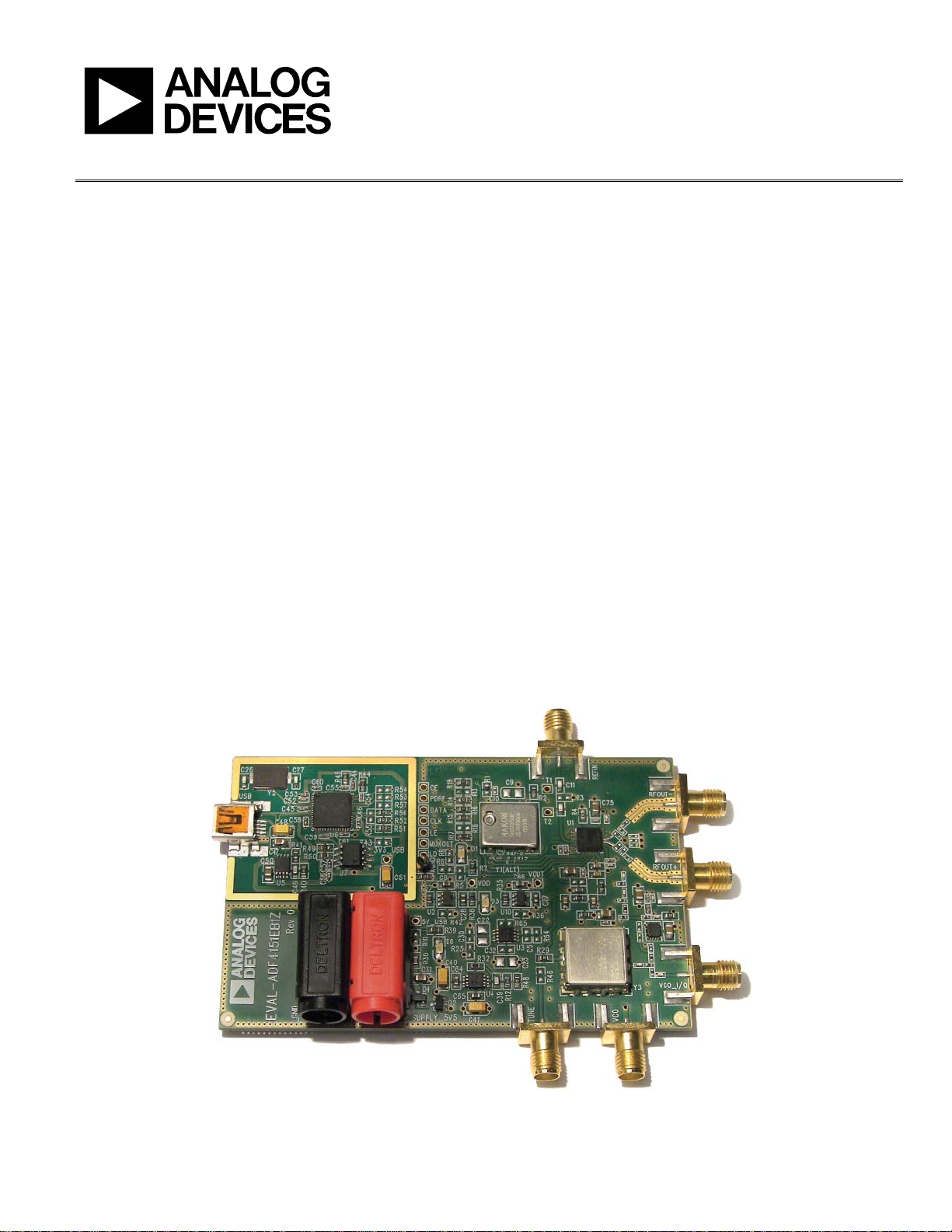
This board is designed to allow the user to evaluate the performance of the ADF4151 frequency synthesizer for phase-locked
loops (PLLs). Figure 1 shows the board, which contains the
ADF4151 synthesizer, loop filter, voltage control oscillator
(VCO), reference oscillator (TCXO) of frequency 25 MHz for
the reference input, power supply connectors, and an RF output.
The evaluation kit also contains software that is compatible with
Windows® XP and later versions to allow easy programming of
the synthesizer.
A USB port in the PC is required to program the part.
EVALUATION BOARD
10482-001
Figure 1. EVAL-ADF4151EB1Z
PLEASE SEE THE LAST PAGE FOR AN IMPORTANT
WARNING AND LEGAL TERMS AND CONDITIONS.
Rev. A | Page 1 of 24

UG-369 Evaluation Board User Guide
TABLE OF CONTENTS
Features .............................................................................................. 1
Evaluation Kit Contents ................................................................... 1
Additional Equipment ..................................................................... 1
Documents Needed .......................................................................... 1
Required Software ............................................................................ 1
General Description ......................................................................... 1
Evaluation Board .............................................................................. 1
Revision History ............................................................................... 2
Quick Start Guide ............................................................................. 3
Evaluation Board Hardware ............................................................ 4
Power Supplies .............................................................................. 4
Input Signals .................................................................................. 4
REVISION HISTORY
2/12—Rev. 0 to Rev. A
Changes to Quick Start Guide Section .......................................... 3
Changes to Power Supply Section .................................................. 4
1/12—Revision 0: Initial Version
Output Signals ...............................................................................4
Default Operation Settings ..........................................................4
Additional Options .......................................................................4
Evaluation Board Setup Procedure .................................................5
Software Installation .....................................................................5
Evaluation Board Software ...............................................................9
Evaluation and Test ........................................................................ 12
Evaluation Board Schematics and Artwork ................................ 13
Ordering Information .................................................................... 21
Bill of Materials ........................................................................... 21
Related Links ............................................................................... 22
Rev. A | Page 2 of 24

Evaluation Board User Guide UG-369
QUICK START GUIDE
Follow these steps to quickly evaluate the ADF4151 device:
1. Install the ADF4151 software.
2. Connect the EVAL-ADF4151EB1Z board to the PC.
3. Follow the hardware driver installation procedure.
4. Connect the power supplies to banana connectors (5.5 V).
5. Run the ADF4151 software.
6. Connect the spectrum analyzer to SMA connector VCO_I/O.
7. Measure the results.
Rev. A | Page 3 of 24
UG-369 Evaluation Board User Guide
EVALUATION BOARD HARDWARE
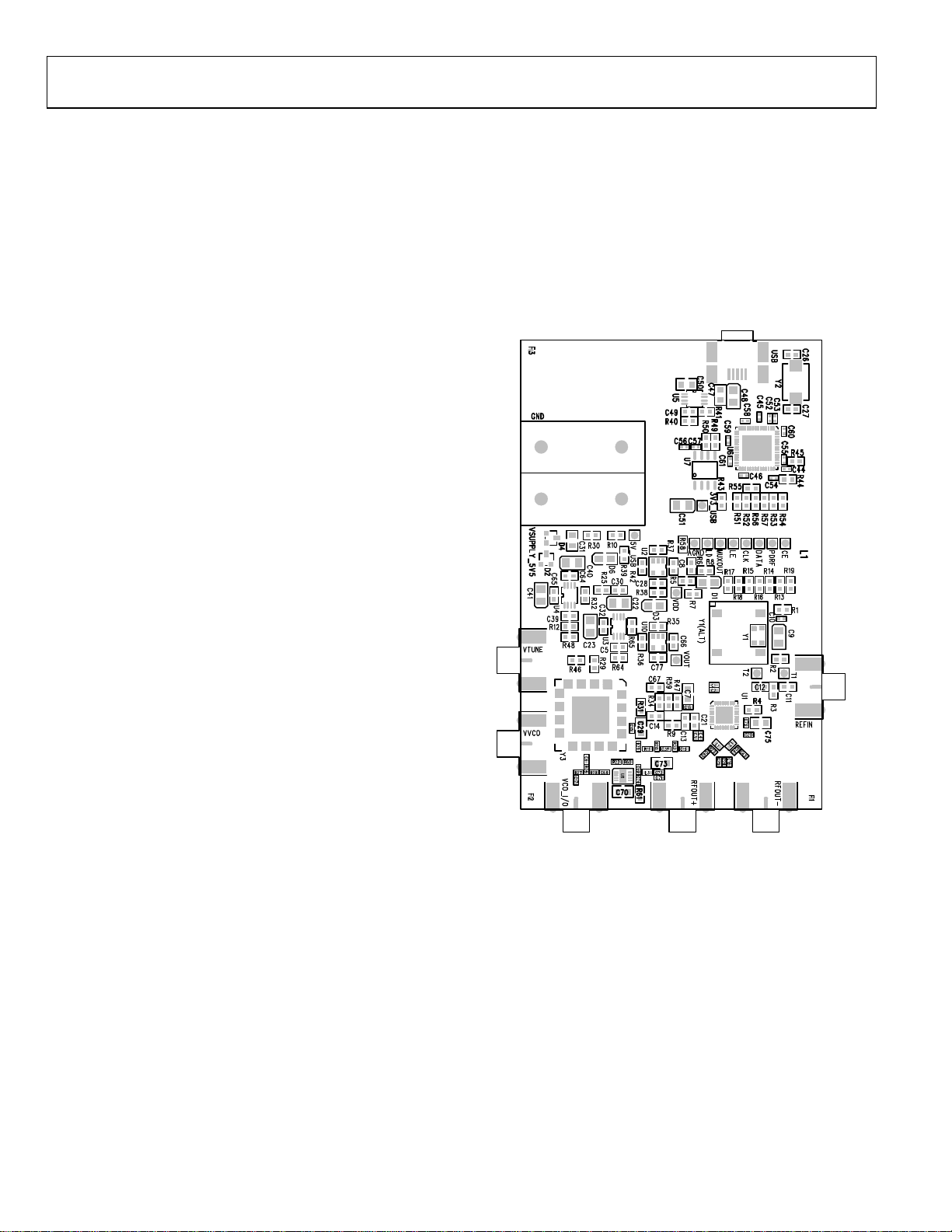
The EVAL-ADF4151EB1Z schematics are shown in Figure 22,
Figure 23, Figure 24, and Figure 25. The silkscreen of the
evaluation board is shown in Figure 2.
POWER SUPPLIES
The board is powered from external banana connectors. The
supplied voltage should be 5.5 V. The power supply circuit uses
high precision, low noise ADP150AUJZ-3.3 linear regulators
and ADP3334ARMZ adjustable LDO regulators to provide 3.3 V
to V
on the board (which supplies the ADF4151 AVDDx, DVDD,
DD
and SDV
pins) to the ADF4151 VDD and 5 V to the ADF4151 VP.
DD
INPUT SIGNALS
The reference signal is necessary for proper operation of the
synthesizer. It can be sourced from a provided TCXO or an
external generator, which can be connected to the REFIN edge
mount connector. To use an external reference generator, it is
necessary to remove R1 and R2 to disconnect TCXO from the
reference input and from the supply.
Digital SPI signals are supplied from the Cypress microcontroller, U6, which is used for communication with the USB port of
the PC.
Optionally, an external VCO can be used. In this case, it is
necessary to remove R29 and insert a 0 Ω link at R46 to form
a connection between the loop filter output and the VTUNE
SMA edge mount connector. Remove R31 to disconnect the
on-board VCO from the power supply. Remove Resistor R26 to
disconnect the output of the on-board VCO from the RF signal
path, and replace Resistors R27 and R28 with 0 Ω links to
ensure operation of the VCO_I/O connector as an input from
an external VCO.
OUTPUT SIGNALS
All components necessary for LO generation are inserted on
the board. The PLL is made up of the ADF4151 synthesizer, a
fourth-order passive loop filter, and the VCO. The loop filter
must be inserted between the charge pump output and the
VCO input, as shown in Figure 25. If replacing the VCO, a
VCO in a T-package (or similar) must be used. The RF output
is available at the edge mount SMA connector, VCO_I/O.
DEFAULT OPERATION SETTINGS
This board is shipped with a TCXO that provides a reference
frequency of 25 MHz, a fourth-order low-pass filter with
30 kHz bandwidth at I
= 2.25 mA, and a VCO with a 1.7 GHz
CP
to 1.8.GHz frequency range. To test the performance of the part
for a different frequency range and different loop filter, the
relevant components on the board must be changed.
ADDITIONAL OPTIONS
The VVCO connector can be used as a test point to measure the
supply voltage of the VCO in its default configuration. It can
also be used to provide an external supply for the on-board VCO;
however, if an external supply for VCO is used, Resistor R31
must be removed to disconnect the connector from the output
of the on-board voltage regulator.
10482-002
Figure 2. Evaluation Board Silkscreen
Rev. A | Page 4 of 24
Evaluation Board User Guide UG-369
EVALUATION BOARD SETUP PROCEDURE
SOFTWARE INSTALLATION
Use the following steps to install the software.
1. Install the Analog Devices ADF4151 software by double-
clicking ADF4151 Setup.msi.
If you are using Windows XP, follow the instructions in the
Windows XP Software Installation Guide section (see
Figure 3 to Figure 7).
If you are using Windows Vista or Windows 7, follow the
instructions in the Windows Vista and Windows 7 Software
Installation Guide section (see Figure 8 to Figure 12).
Note that the software requires Microsoft Windows
Installer and Microsoft .NET Framework 3.5 (or higher).
The installer connects to the Internet and downloads
Microsoft .NET Framework automatically. Alternatively,
before running the ADF4151 Setup.msi, both the installer
and .NET Framework can be installed from the CD that is
provided.
2. Connect your board by USB.
If you are using Windows XP, follow the steps in the
Windows XP Driver Installation Guide section (see Figure 13
to Figure 16).
On Windows Vista or Windows 7, the drivers install
automatically.
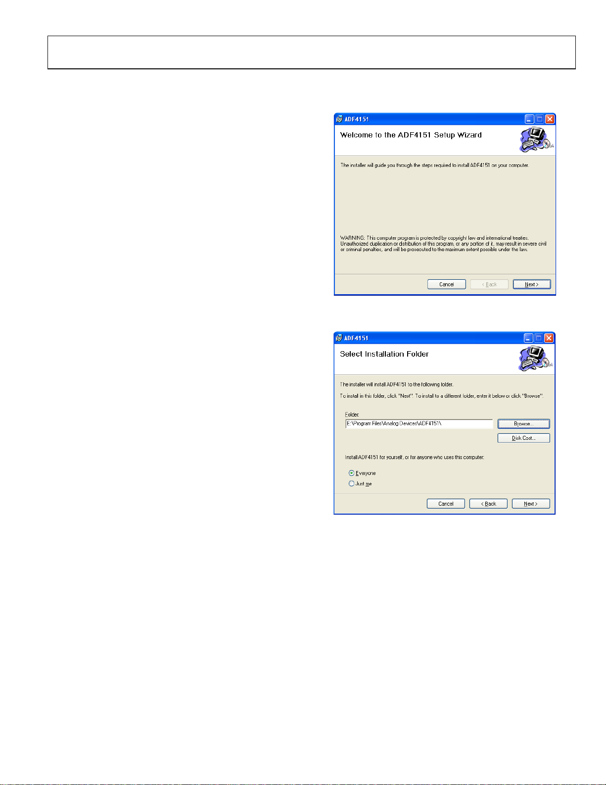
Windows XP Software Installation Guide
Figure 3. Windows XP ADF4151 Software Installation, Setup Wizard
1. Click Next >.
Figure 4. Windows XP ADF4151 Software Installation, Select Installation
Folder
2. Choose an installation directory and click Next >.
10482-003
10482-004
Rev. A | Page 5 of 24
UG-369 Evaluation Board User Guide
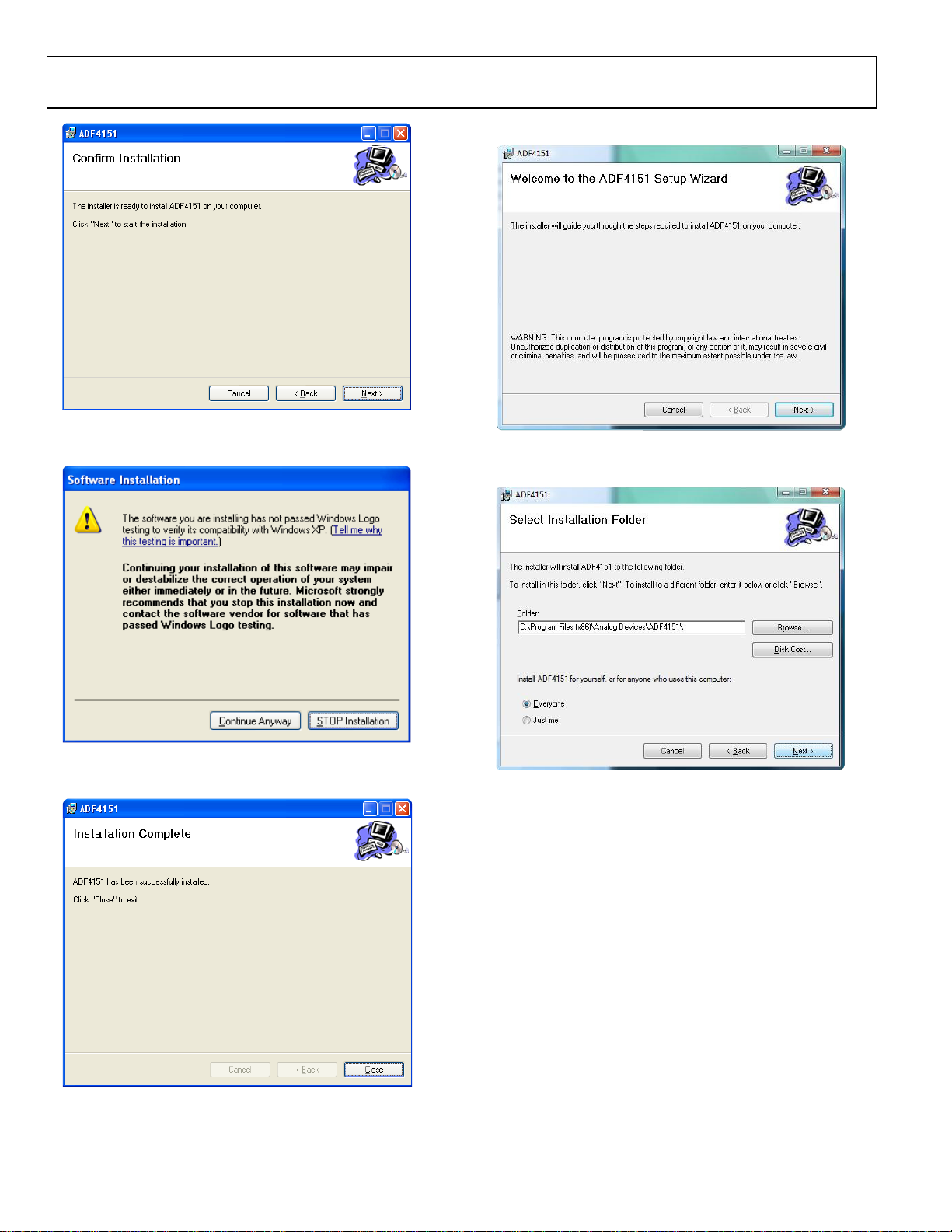
Windows Vista and Windows 7 Software Installation Guide
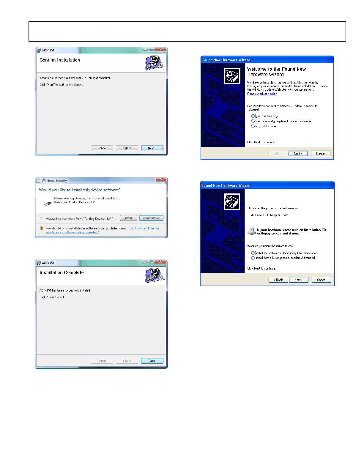
Figure 5. Windows XP ADF4151 Software Installation, Confirm Installation
3. Click Next >.
10482-005
Figure 8. Windows Vista/7 ADF4151 Software Installation, Setup Wizard
1. Click Next >.
10482-008
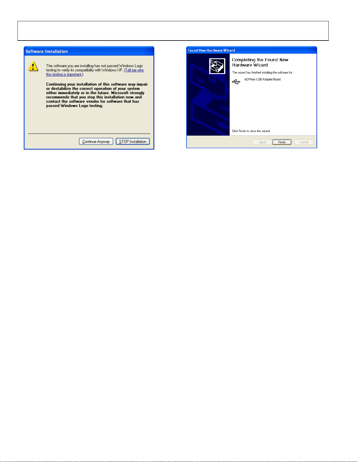
Figure 6. Windows XP ADF4151 Software Installation, Logo Testing
4. Click Continue Anyway.
Figure 7. Windows XP ADF4151 Software Installation, Installation Complete
5. Click Close.
Rev. A | Page 6 of 24
10482-006
10482-009
Figure 9. Windows Vista/7 ADF4151 Software Installation, Select Installation
Folder
2. Choose an installation directory and click Next >.
10482-007
Evaluation Board User Guide UG-369
Windows XP Driver Installation Guide
Figure 10. Windows Vista/7 ADF4151 Software Installation, Confirm Installation
3. Click Next >.
10482-010
Figure 13. Windows XP USB Driver Installation, Found New Hardware Wizard
1. Choose Yes, this time only and click Next >.
10482-013
Figure 11. Windows Vista/7 ADF4151 Software Installation, Start Installation
4. Click Install.
Figure 12. Windows Vista/7 ADF4151 Software Installation, Install Complete
5. Click Close.
10482-011
Figure 14. Windows XP USB Driver Installation, Install Options
10482-014
2. Click Next >.
Note that Figure 14 may list Analog Devices RFG.L Eval Board
instead of ADF4xxx USB Adapter Board.
10482-012
Rev. A | Page 7 of 24
UG-369 Evaluation Board User Guide
Figure 15. Windows XP USB Driver Installation, Logo Testing
10482-015
3. Click Continue Anyway.
Figure 16. Windows XP USB Driver Installation, Complete Installation
4. Click Finish.
10482-016
Rev. A | Page 8 of 24

Evaluation Board User Guide UG-369
EVALUATION BOARD SOFTWARE
The control software for the EVAL-ADF4151EB1Z is available
on the CD included in the evaluation kit. To install the software,
see the Software Installation section.
To run the software, first connect the board to the USB port of
the PC and then click the ADF4151 file on the desktop or in the
Start menu. Confirm that USB OK is displayed at the top right
corner of the software front panel display window (see Figure 17).
Otherwise, the software has no connection to the evaluation board.
Note that, when connecting the board, it takes about 5 sec to
10 sec for the status label to change.
If the software is started before the board is connected to USB
port, an error window opens, informing that the USB device
was not found, and the No USB message is displayed in the top
right corner of the software front panel window. In this case,
connect the board to the USB port and click the Connect USB
button.
Figure 17. Software Front Panel Display—Select Device and Connection
Rev. A | Page 9 of 24
10482-017

UG-369 Evaluation Board User Guide
Use the Frequency text box in the Reference section to set the
correct reference frequency. The default reference on the
software window is at 25 MHz and matches the frequency of the
TCXO present on the board.
Use the VCO Output Frequency section to control the output
frequency. To achieve single-tone on the VCO output, type the
desired output frequency in the Activate f1 text box (in megahertz) and ensure that Stop is selected in the Dynamic section
under VCO Output Frequenc y. Selecting the Alternate option
causes the frequency on the VCO output to switch between the
Activate f1 and Activate f2 values. The delay time between
frequency switches is controlled by the Approximate Delay
option. The third option of the Dynamic section, Sweep, allows
the output frequency to constantly change with the frequency
step set by Channel Spacing, starting from Activate f1 until it
reaches Activate f2. After the Active f2 frequency is reached,
the sweep is repeated.
Some register settings may need to be set manually. Click the
Register 1 to Register 5 buttons to open the register settings
windows, as shown in Figure 18.
Click the REGISTERS button to display the binary and
hexadecimal values for all registers, as shown in Figure 19.
When a new register setting value is entered (see Figure 18),
the relevant Update Rx (where x = 0 to 5) button becomes red,
indicating that it must be clicked to program the part with the
new value. Clicking the Update ALL button programs all
register values simultaneously.
Click the OK button to confirm the new value in the Register x
Settings (where x = 1, 2, 3, or 5) window (see Figure 18). Click
Update Rx to program the part with the new value. The new
value is retained in the Register x Settings window if it is
opened again.
If the value entered is outside of the range specified in the
ADF4151 data sheet, an error message appears and the field is
automatically updated to the lowest or highest value within the
allowed range. Some limits are changed dynamically based on
the values of other registers; that is, the highest allowed value
for Phase in the Register 1 Settings window depends on the
current value of the modulus (MOD in the Settings section),
which is calculated based on the data from the Reference
section and the Channel Spacing field (under the VCO Output
Frequency section).
Click the Cancel button to abandon a register value change, and
the new value is not retained in the Register x Settings window
if it is opened again.
Figure 18. Register Settings Windows for Register 1, Register 2, Register 3, and Register 5
10482-018
Rev. A | Page 10 of 24

Evaluation Board User Guide UG-369
10482-019
Figure 19. Registers Window for Register 1, Register 2, Register 3, and Register 5
Rev. A | Page 11 of 24

UG-369 Evaluation Board User Guide
EVALUATION AND TEST
To evaluate and test the performance of the ADF4151, use the
following procedure:
1. If using a different VCO and loop filter than provided on
the board, ensure that a VCO and loop filter are properly
inserted on the board. Use ADIsimPLL to generate the
loop filter component values.
2. Install the ADF4151software. Connect the evaluation
board to a PC using the supplied USB cable. Follow the
hardware driver installation procedure that appears.
3. If the on-board crystal oscillator is used, skip this step. If
an external reference is necessary, connect a reference
signal to the REFIN edge mount connector.
4. Connect the power supply to the board.
5. Connect a spectrum analyzer to Connector VCO_I/O.
6. Run the ADF4151 software.
7. In the software window, set the VCO center frequency
(Figure 20 shows a screenshot of a spectrum analyzer taken
at a frequency of 1750 MHz, which is in the middle range
of the provided VCO). Set the PFD frequency as defined in
ADIsimPLL, and program the reference frequency to 25
MHz if the on-board TCXO is used or to the frequency
that has been supplied to the REFIN connector. See Figure 21
for the suggested setup.
8. Measure the output spectrum. Figure 20 shows a
1750 MHz output.
GENERATOR
SIGNAL
Ref 0 dBm
0
-10
1AP
CLRWR
-20
-30
-40
-50
-60
-70
-80
-90
-100
Date: 14.DEC.2011 16:44:31
*
RBW 20 kHz
*
Att 5 dB
VBW 50 kHz
SWT 20 ms
1
200 kHz/Center 1.749996795 GHz Span 2 MHz
Marker 1 [T1 ]
-5.28 dBm
1.749996795 GHz
Figure 20. Spectrum Analyzer Display
A
3DB
10482-020
REFERENCE
(OPTIONAL)
PC
PLL
POWER
LED
TCXO
R59
C67
PLL
R47
C14
R34
LOOP FILTER
VCO
C21
C13
R9
SPECTRUM
ANALYZER
10482-021
POWER
SUPPLIES
USB
EXTERNAL DC
LOCK
DETECT
LED
USB LED
SUPPLY
SUPPLY
EXTERNAL DC
Figure 21. Typical Evaluation Setup
Rev. A | Page 12 of 24

Evaluation Board User Guide UG-369
EVALUATION BOARD SCHEMATICS AND ARTWORK
DNI
D1
VDD
VDD
R6
LD
DNI
R5
VDD
1uF
10pF
C7
C16
VP
10pFC40.1uF
0.1uF
C1
C3
AGND
Lock Detect
1k
R7
AGND
AGND
R8 DNI
AGND
5k1
R4
10pF
C2
AGND
T2
MUXOUT
1uF
10pF
C75
7
VDD
CPOUT
CPOUT
FLSW
5
SW
C76
16
AVDD
U1
ADF4151
CLK2DATA3LE4CE
1
MUXOUT
25
30
LD
MUXOUT
RSET
22
VP
6
DVDD
28
SDVDD
32
AVDD2
17
AVDD1
10
REFIN
29
10482-022
DNI
C24
VOUT
R23 DNI
12NC13
AGND
SDGND
21
31
RFOUT-
DNI
C43
DNI
C25
DNI
L2
R24 DNI
NC
DGND
CPGND
PADDLE
8
27
33
AGND
RFOUT+
DNI
C42
DNI
C18
RF_IN
C19
100pF
AGND
100pF
15
RFIN-
26
L1 DNI
C20
14
RFIN+
AGND
DGND
AGND
AGND
9
11
18
R3
DNI
R2
3
OUT
GND
25MHz
Y1(ALT)
VCC
4
3
VDD
OUT
Y1
VCC
4
C10
+
C9
R1
2
C12 1nF
0r
C11 1nF
T1
REFIN
1
GND
2
GND
0.1uF
VDD
DNI
CLK DATA LE CE
10k
R19
R18
DNI
LE
CE
CLK
DATA
Figure 22. Evaluation Board Schematic (Page 1)
0r
VDD
R17
10k
R16
10k
R15
10k
R13
PDRF
R14
DNI
PDRF
AGND
Rev. A | Page 13 of 24

UG-369 Evaluation Board User Guide
VP
0r
R48
VDD
VDD
5
VOUT
VOUT
U10
C77
1uF
5
VOUT
2
GND
ADP150-TSOT
VIN
EN
1
3
0r
DNI
R36
R35
C66
1uF
VOUT
U2
ADP150-TSOT
VIN
1
D3
1k
R38
C28
1uF
2
GND
EN
3
0r
DNI
R42
R37
C8
1uF
VP
DNI
C23
+
C32
DNI
DNI
R64
DNI
C5
2
3FB4
1
NC
OUT
OUT
U3
R65
IN
GND8IN
7
6SD5
DNI
C22
+
C30
DNI
+5V
C41
C65
R12
C39
3FB4
2
1
NC
OUT
OUT
U4
DNI
GND8IN
IN
6SD5
7
C40
C64
10482-023
22uF
+
1uF
210K
1nF
R32
64K9
22uF
+
1uF
DNI
R25
DNI
R10
5V_USB
1r
R30
1uF
C31
D4
7.5V
D2
BZX84C7V5
BANANA-RED
VSUPPLY_5V5
GND
BANANA-BLACK
Figure 23. Evaluation Board Schematic (Page 2)
Rev. A | Page 14 of 24

Evaluation Board User Guide UG-369
2K2
R50
3V3-USB
C27
2K2
R49
MUXOUT
3V3-USB
10pF
C56
R43
SCREEN BOX
22uF
C51
3V3-USB
3V3_USB
U5
+
C50
1uF
140K
R40
1nF
C49
1
3FB4
78K7
NC
OUT2OUT
ADP3334
GND6SD7IN8IN
R41
5
C48
22uF
+
C47
1uF
3V3-USB
3V3-USB
0.1uF
C53
C52 10pF
3V3-USB
3V3-USB
DNI
18
PB0/FD019PB1/FD120PB2/FD221PB3/FD3
VCC
55
VCC
43
VCC
32
VCC
27
VCC
17
VCC
11
VCC
7
AVCC
3
100k
R45
100k
R44
46
25
PB7/FD724PB6/FD623PB5/FD522PB4/FD4
PD1/FD945PD0/FD8
U6
*WAKEUP42RESET
CLKOUT
44
54
0.1uF
C55
0.1uF
C54
8
7WP6
U7
PD5/FD1351PD6/FD1452PD7/FD15
R52
LE
0r
CLK
VCC
1A02A13A24
R55
5
SCL
30
DNI
R53
DNI
SDA
VSS
CTL1/*FLAGB29CTL0/*FLAGA
24LC64
4
5
15
16
31
SCL
SDA
CTL2/*FLAGC
PA7/*FLD/SLCS39PA6/*PKTEND38PA5/FIFOADR137PA4/FIFOADR036PA3/*WU235PA2/*SLOE34PA1/INT133PA0/INT0
40
DNI
R54
R56
DATA
XTALIN
XTALOUT
RDY0/*SLRD2RDY1/*SLWR
IFCLK14RSVD
1
13
DNI
R57
0r
0.1UF
C57
3V3-USB
49
50
PD4/FD1248PD3/FD1147PD2/FD10
CY7C68013-CSP
D-
8D+9
0r
R51
3V3-USB
12pF
Y2
24.0MHz
C26
12pF
GND
56
GND
53
GND
41
GND
28
GND
26
GND
12
GND
10
AGND
6
C61
C60
C59
C58
CE
PDRF
C46
C45
Decoupling for U7 - place one close to each VCC pin
C44
3V3-USB
10482-024
0.1uF
0.1uF
0.1uF
0.1uF
0.1uF
0.1uF
0.1uF
5V_USB
2K2
R39
5V_USB
D6
USB
1
VBUS
USB-MINI-B
2D-3D+4IO5
SHLD17SHLD28SHLD39SHLD4
6
GND
R58
DGND
0r
AGND
Figure 24. Evaluation Board Schematic (Page 3)
Rev. A | Page 15 of 24

UG-369 Evaluation Board User Guide
C73
+5V
C74 68pF
0r
+5V
R61
U8
C68
R28
+5V
R26
0r
R31
1uF
1.2nF
C72
68pF
C71
L3
47nH
33pF
C69
5
8
DNI
VPOS
RFOUT
ADL5541
RFIN
CB
1
4
33pF
18r
18r
R60
GND
7
GND
6
GND
3
GND
2
C70
1uF
R22
DNI
18r
R27
150r
R11
68r
R21
68r
R20
10482-025
RF_IN
51r
R33
C37
100pF
VVCO
C6
100pF
C17
1uF
C29
C15
10
10pF
RF
14
Y3
VCC
VT
2
0r
R29
R46
DNI
VTUNE
R34
75r
R9
75r
CPOUT
100pF
VCO_I/O
ROS-1800+
4.7nF
C67
FLSW
4.7nF
C14
DNI
R47
C13
120nF
C21
6.8nF
AGND
R59
120r
Figure 25. Evaluation Board Schematic (Page 4)
Rev. A | Page 16 of 24

Evaluation Board User Guide UG-369
10482-026
Figure 26. Layer 1 (Component Side)
Rev. A | Page 17 of 24

UG-369 Evaluation Board User Guide
10482-027
Figure 27. Layer 2 (Ground Plane)
Rev. A | Page 18 of 24

Evaluation Board User Guide UG-369
10482-028
Figure 28. Layer 3 (Power Plane)
Rev. A | Page 19 of 24

UG-369 Evaluation Board User Guide
10482-029
Figure 29. Layer 4 (Solder Side)
Rev. A | Page 20 of 24

Evaluation Board User Guide UG-369
ORDERING INFORMATION
BILL OF MATERIALS
Table 1.
Reference Designator Value Description Manufacturer/Part Number
AGND Black test point Vero 20-2137
C1, C4, C10, C44, C45, C46, C53, C54,
C55, C57, C58, C59, C60, C61
C2, C3, C15, C16, C52, C56, C76 10 pF 50 V NP0 ceramic capacitor AVX 04025U100GAT2A
C5, C24 Do not insert 50 V NP0 ceramic capacitor Not applicable
C6, C17, C19, C20, C37 100 pF 50 V C0G ceramic capacitor Murata GRM1555C1H101JD01D
C7, C29, C31 1 μF Ceramic capacitor 1.0 μF, 50 V, X5R, 0805 Taiyo/Yuden GRM32RR71H105KA01L
C8, C28, C66, C77 1 μF Capacitor, 0603, 1 μF, 10 V, X5R Murata GRM188R61A105KA61D
C9 Do not insert TAJ-A capacitor location, not inserted Not applicable
C11, C12, C39, C49 1 nF 50 V NP0 ceramic capacitor AVX 06035A102JAT2A
C13 120 nF 50 V X7R SMD ceramic capacitor Kemet C0603C124K5RACTU
C14, C67 4.7 nF 50 V X7R SMD ceramic capacitor Kemet C0603C472K5RAC
C18, C25, C30, C32 Do not insert 16 V X5R ceramic capacitor Not applicable
C21 6.8 nF 50 V NP0 SMD ceramic capacitor Kemet C0603C682J5GACTU
C22, C23 Do not insert 6.3 V tantalum capacitor (TAJ-A case) Not applicable
C26, C27 12 pF 50 V NP0 SMD ceramic capacitor Phycomp 2238 867 15129
C40, C41, C48, C51 22 μF 6.3 V tantalum capacitor (TAJ-A case) AVX TAJA226K006R
C42, C43 Do not insert
C47, C50 1.0 μF
C64, C65 1 μF 16 V X5R ceramic capacitor Kemet C0603C105K4PAC-TU
C68, C69 33 pF 50 V C0G ceramic capacitor Murata GRM1555C1H330JZ01D
C70, C73, C75 1.0 μF Ceramic capacitor 1.0 μF, 50 V, X5R, 0805 Taiyo/Yuden GRM32RR71H105KA01L
C71, C74 68 pF 50 V C0G ceramic capacitor Murata GRM1555C1H680JZ01D
C72 1.2 nF 50 V X7R ceramic capacitor Murata GRM155R71H122KA01D
D1, D6 Green LED Avago Technologies, HSMG-C170
D2 7.5 V Zener diode, 7.5 V, 300 mW Fairchild BZX84C7V5
D3 Red LED Avago Technologies HSMS-C170
D4 Schottky diode,1 A forward Avago Technologies HSMS-280C-BLKG
GND Black 4 mm banana socket Deltron 571-0100-01
L1, L2 Do not insert 0402 inductor location, not inserted Not applicable
L3 47 nH Coilcraft 0402CS SMD inductor Coilcraft 0402CS-47NX-LU
R1, R2, R14, R29, R31, R35, R37, R48,
R51, R52, R56, R58, R61
R3, R5, R6, R8, R10, R13, R18, R22,
R23, R24, R25, R36, R42, R43, R46,
R47, R53, R54, R55, R57, R60, R64, R65
R4 5.1 kΩ SMD resistor Multicomp MC 0.063W 0603 5k1
R7, R38 1 kΩ SMD resistor Multicomp MC 0.063W 0603 1K
R9, R34 75 Ω SMD resistor
R11 150 Ω 0402 SMD resistor Multicomp MC 0.0625W 0402 1% 150R
R12 210 kΩ SMD resistor Multicomp MC 0.063W 0603 210k
R15, R16, R17, R19 10 kΩ SMD resistor Multicomp MC 0.063W 0603 10K
R20, R21 68 Ω 0402 SMD resistor Multicomp MC 0.0625W 0402 1% 68R
R33 51 Ω 0402 SMD resistor Multicomp MC 0.063W 0402 51R
R26, R27, R28 18 Ω 0402 SMD resistor Multicomp MC 0.0625W 0402 1% 18R
R30 1 Ω SMD resistor Yageo (PHYCOMP) RC0603FR-071RL
R32 64.9 kΩ SMD resistor Multicomp MC 0.063W 0603 68k
R39, R49, R50 2.2 kΩ SMD resistor Multicomp MC 0.063W 0603 2k2
0.1 μF 16 V, X7R ceramic capacitor Kemet C0402C104K4RAC
Ceramic capacitor, 1000 pF 50 V C0G
0402
Ceramic capacitor, 1.0 μF, 25 V, X5R,
0805
0 Ω SMD resistor Multicomp MC 0.063W 0603 0R
Do not insert 0603 resistor location, not inserted Not applicable
Rev. A | Page 21 of 24
Not applicable
Taiyo/Yuden TMK107BJ105KA-T
CRCW060375R0FKEA

UG-369 Evaluation Board User Guide
Reference Designator Value Description Manufacturer/Part Number
R40 140 kΩ SMD resistor Multicomp MC 0.063W 0603 1% 140K
R41 78.7 kΩ SMD resistor Multicomp MC 0.063W 0603 1% 78K7
R44, R45 100 kΩ SMD resistor Multicomp MC 0.063W 0603 100K
R59 120 Ω SMD resistor Multicomp MC 0.063W 0603 1% 120R
REFIN, RFOUT+, RFOUT− End-launch 50 Ω SMA jack Emerson Network 142-0701-851
U1 PLL Analog Devices ADF4151
U2, U10 3.3 V linear regulator Analog Devices ADP150AUJZ-3.3
U3, U4, U5 Adjustable LDO regulator Analog Devices ADP3334ARMZ
U6 USB microcontroller
U7 64 k I2C serial EEPROM Microchip Technology 24LC64-ISN
U8 50 MHz to 6 GHz RF/IF gain block Analog Devices ADF4151ACPZ
USB USB Mini-B connector (USB-OTG) Molex 54819-0578
VCO_I/O, VTUNE, VVCO End-launch 50 Ω SMA jack Emerson Network 142-0701-851
VSUPPLY_5V5 Red 4 mm banana socket Deltron 571-0500-01
Y1 (ALT) 25 MHz
Y2 24 MHz SMD crystal ECS International ECS-240-12-20A-TR
Y3
1700 MHz to
1800 MHz
SMD temperature compensated crystal
oscillator
VCO Mini-Circuits ROS-1800+
Cypress Semiconductor
CY7C68013A-56LFXC
Rakon TXO225B
RELATED LINKS
Resource Description
ADF4151 Product Page, Fractional-N/Integer-N PLL Synthesizer
ADP150 Product Page, Ultralow Noise, 150 mA CMOS Linear Regulator
ADP3334 Product Page, High Accuracy Low IQ, 500 mA anyCAP® Adjustable Low Dropout Regulator
Rev. A | Page 22 of 24

Evaluation Board User Guide UG-369
NOTES
Rev. A | Page 23 of 24

UG-369 Evaluation Board User Guide
NOTES
I2C refers to a communications protocol originally developed by Philips Semiconductors (now NXP Semiconductors).
ESD Caution
ESD (electrostatic discharge) sensitive device. Charged devices and circuit boards can discharge without detection. Although this product features patented or proprietary protection
circuitry, damage may occur on devices subjected to high energy ESD. Therefore, proper ESD precautions should be taken to avoid performance degradation or loss of functionality.
Legal Terms and Conditions
By using the evaluation board discussed herein (together with any tools, components documentation or support materials, the “Evaluation Board”), you are agreeing to be bound by the terms and conditions
set forth below (“Agreement”) unless you have purchased the Evaluation Board, in which case the Analog Devices Standard Terms and Conditions of Sale shall govern. Do not use the Evaluation Board until you
have read and agreed to the Agreement. Your use of the Evaluation Board shall signify your acceptance of the Agreement. This Agreement is made by and between you (“Customer”) and Analog Devices, Inc.
(“ADI”), with its principal place of business at One Technology Way, Norwood, MA 02062, USA. Subject to the terms and conditions of the Agreement, ADI hereby grants to Customer a free, limited, personal,
temporary, non-exclusive, non-sublicensable, non-transferable license to use the Evaluation Board FOR EVALUATION PURPOSES ONLY. Customer understands and agrees that the Evaluation Board is provided
for the sole and exclusive purpose referenced above, and agrees not to use the Evaluation Board for any other purpose. Furthermore, the license granted is expressly made subject to the following additional
limitations: Customer shall not (i) rent, lease, display, sell, transfer, assign, sublicense, or distribute the Evaluation Board; and (ii) permit any Third Party to access the Evaluation Board. As used herein, the term
“Third Party” includes any entity other than ADI, Customer, their employees, affiliates and in-house consultants. The Evaluation Board is NOT sold to Customer; all rights not expressly granted herein, including
ownership of the Evaluation Board, are reserved by ADI. CONFIDENTIALITY. This Agreement and the Evaluation Board shall all be considered the confidential and proprietary information of ADI. Customer may
not disclose or transfer any portion of the Evaluation Board to any other party for any reason. Upon discontinuation of use of the Evaluation Board or termination of this Agreement, Customer agrees to
promptly return the Evaluation Board to ADI. ADDITIONAL RESTRICTIONS. Customer may not disassemble, decompile or reverse engineer chips on the Evaluation Board. Customer shall inform ADI of any
occurred damages or any modifications or alterations it makes to the Evaluation Board, including but not limited to soldering or any other activity that affects the material content of the Evaluation Board.
Modifications to the Evaluation Board must comply with applicable law, including but not limited to the RoHS Directive. TERMINATION. ADI may terminate this Agreement at any time upon giving written notice
to Customer. Customer agrees to return to ADI the Evaluation Board at that time. LIMITATION OF LIABILITY. THE EVALUATION BOARD PROVIDED HEREUNDER IS PROVIDED “AS IS” AND ADI MAKES NO
WARRANTIES OR REPRESENTATIONS OF ANY KIND WITH RESPECT TO IT. ADI SPECIFICALLY DISCLAIMS ANY REPRESENTATIONS, ENDORSEMENTS, GUARANTEES, OR WARRANTIES, EXPRESS OR IMPLIED, RELATED
TO THE EVALUATION BOARD INCLUDING, BUT NOT LIMITED TO, THE IMPLIED WARRANTY OF MERCHANTABILITY, TITLE, FITNESS FOR A PARTICULAR PURPOSE OR NONINFRINGEMENT OF INTELLECTUAL
PROPERTY RIGHTS. IN NO EVENT WILL ADI AND ITS LICENSORS BE LIABLE FOR ANY INCIDENTAL, SPECIAL, INDIRECT, OR CONSEQUENTIAL DAMAGES RESULTING FROM CUSTOMER’S POSSESSION OR USE OF
THE EVALUATION BOARD, INCLUDING BUT NOT LIMITED TO LOST PROFITS, DELAY COSTS, LABOR COSTS OR LOSS OF GOODWILL. ADI’S TOTAL LIABILITY FROM ANY AND ALL CAUSES SHALL BE LIMITED TO THE
AMOUNT OF ONE HUNDRED US DOLLARS ($100.00). EXPORT. Customer agrees that it will not directly or indirectly export the Evaluation Board to another country, and that it will comply with all applicable
United States federal laws and regulations relating to exports. GOVERNING LAW. This Agreement shall be governed by and construed in accordance with the substantive laws of the Commonwealth of
Massachusetts (excluding conflict of law rules). Any legal action regarding this Agreement will be heard in the state or federal courts having jurisdiction in Suffolk County, Massachusetts, and Customer hereby
submits to the pers onal jurisdiction and venu e of such courts. The United Nations Conventi on on Contracts for the Internation al Sale of Goods shall not apply to this Agreement and is expressly disclaimed.
©2012 Analog Devices, Inc. All rights reserved. Trademarks and
registered trademarks are the property of their respective owners.
UG10482-0-2/12(A)
Rev. A | Page 24 of 24
 Loading...