

Evaluation Board User Guide
UG-160
09145-001
One Technology Way • P. O. Box 9106 • Norwood, MA 02062-9106, U.S.A. • Tel: 781.329.4700 • Fax: 781.461.3113 • www.analog.com
Evaluation Board for the Integer-N PLL Frequency Synthesizer
FEATURES
Self-contained board for generating RF frequencies
Contains ADF4108 8 GHz frequency synthesizer IC
Accompanying software allows complete control of
synthesizer functions from a PC
EVALUATION KIT CONTENTS
EV-ADF4108EB1Z board
CD that includes:
Self-installing software that allows users to control the
board and exercise all functions of the device
Electronic version of the ADF4108 data sheet
Electronic version of the UG-160 user guide
ADDITIONAL EQUIPMENT
PC running Windows XP or more recent version
Spectrum analyzer
Oscilloscope (optional)
Power supplies of 5.5 V and 15 V
DOCUMENTS NEEDED
ADF4108 data sheet
REQUIRED SOFTWARE
Analog Devices Int-N software (Version 7 or higher)
ADIsimPLL
GENERAL DESCRIPTION
This board is designed, to let the user evaluate the performance of
the ADF4108 frequency synthesizer for phase-locked loops
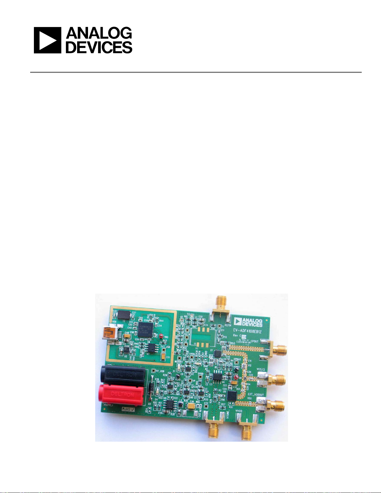
(PLLs). Figure 1 shows the board, which contains the ADF4108
synthesizer, an SMA connector for the reference input, power
supplies, a USB interface, and RF outputs. There is also an
active loop filter and a VCO on board. The board has the option
to use an alternate loop filter and VCO by connecting to the
SMA connectors, VTUNE, an d C POU T. The evaluation kit
contains software that is compatible with Windows® XP and
later versions to allow easy programming of the synthesizer.
The USB interface allows software programming of the ADF4108
device. A USB cable is included with the board to allow software
programmability.
PLEASE SEE THE LAST PAGE FOR AN IMPORTANT
WARNING AND LEGAL TERMS AND CONDITIONS.
EVALUATION BOARD
Figure 1. EV-ADF4108EB1Z
Rev. A | Page 1 of 20

UG-160 Evaluation Board User Guide
TABLE OF CONTENTS
Features .............................................................................................. 1
Evaluation Kit Contents ................................................................... 1
Additional Equipment ..................................................................... 1
Documents Needed .......................................................................... 1
Required Software ............................................................................ 1
General Description ......................................................................... 1
Evaluation Board .............................................................................. 1
Revision History ............................................................................... 2
Quick Start Guide ............................................................................. 3
Evaluation Board Hardware ............................................................ 4
Power Supplies .............................................................................. 4
REVISION HISTORY
3/12—Rev. 0 to Rev. A
Changes to Features Section and General Description
Section ................................................................................................ 1
Added Evaluation Kit Contents Section, Additional Equipment
Section, Documents Needed Section, Required Software
Section, and Evaluation Board Section; Deleted Block Diagram
Section; Replaced Figure 1 .............................................................. 1
Added Quick Start Guide Section .................................................. 3
Deleted Hardware Description Section and Figure 3,
Renumbered Sequentially ................................................................ 3
Changes to Evaluation Board Hardware Section and Power
Supplies Section ................................................................................ 4
Replaced Figure 2; Added Input Signals Section, Output Signals
Section, and Default Operations Section ...................................... 4
Deleted Software Description Section, Programmable Software
Settings Section, and Figure 4 ......................................................... 4
Added Evaluation Board Setup Procedure Section Software
Installation Section, and Figure 3 to Figure 5 ............................... 5
Added Windows Vista and Windows 7 Software Installation
Guide Section and Figure 6 to Figure 9 ......................................... 6
Added Windows XP Driver Installation Guide Section and
Figure 10 to Figure 14 ...................................................................... 7
Added Figure 15 and Figure 16....................................................... 8
Input Signals...................................................................................4
Output Signals ...............................................................................4
Default Operation .........................................................................4
Evaluation Board Setup Procedure .................................................5
Software Installation .....................................................................5
Evaluation Board Software ...............................................................8
Evaluation and Test ........................................................................ 10
Evaluation Board Schematics and Artwork ................................ 12
Ordering Information .................................................................... 18
Bill of Materials ........................................................................... 18
Related Links ................................................................................... 19
Changes to Evaluation Board Software Section, Added
Figure 17 ............................................................................................. 9
Added Figure 18 ............................................................................. 10
Added Evaluation and Test Section, Figure 19, and
Figure 20 .......................................................................................... 11
Changed Evaluation Board Schematics Section to Evaluation
Board Schematics and Artwork Section ...................................... 12
Changes to Figure 21 ...................................................................... 12
Changes to Figure 22 ...................................................................... 13
Added Figure 23 ............................................................................. 14
Added Figure 24 ............................................................................. 15
Added Figure 25 ............................................................................. 16
Added Figure 26 ............................................................................. 17
Added Figure 27 ............................................................................. 18
Added Figure 28 ............................................................................. 19
Changes to Table 1 .......................................................................... 18
Added Related Links Section ................................
7/11—Revision 0: Initial Version
........................ 19
Rev. A | Page 2 of 20

Evaluation Board User Guide UG-160
QUICK START GUIDE
Use the following steps to evaluate the ADF4108 device:
1. Install the Int-N software.
2. Follow the hardware driver installation procedure.
3. Connect the power supplies to the EV-ADF4108EB1Z:
a. The 5.5 V power supply to the on-board banana connectors.
b. The 15 V power supply to test points labeled +15 V and AGND1.
4. Connect the USB cable to the PC and to the EV-ADF4108EB1Z.
5. Run the Int-N software.
6. Select the ADF4108 device and the USB board in the Select Device and Connection tab of the software front panel window.
7. Ensure that the message “board connected” appears on front panel.
8. Connect the reference frequency to REFIN (SMA).
9. Click the Main Controls tab to input RF Settings and Settings.
10. Note that the Phase Detector Polarity drop-down list in the Settings section should be set to Negative to suit the active loop filter in
inverting mode.
11. Update all registers.
12. Connect the output to a signal source analyzer. The board offers two outputs.
a. VCO/2 via SMA labeled VCO/2
b. VCO via SMA labeled EXT_VCOOUT
13. Measure the results.
Rev. A | Page 3 of 20
UG-160 Evaluation Board User Guide
09145-002
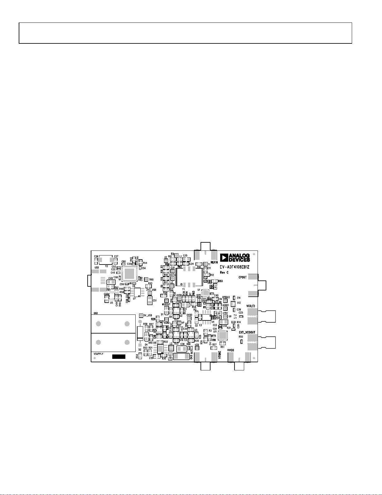
EVALUATION BOARD HARDWARE
The evaluation board comes with a mini-USB cable to connect to
the USB port of a PC. The evaluation board silkscreen is shown
in Figure 2. The EV-ADF4108EB1Z schematics are shown in
Figure 21, Figure 22, Figure 23, and Figure 24.
POWER SUPPLIES
The board is powered via two external supplies, 5.5 V and 15 V,
and connected as described in the Quick Start Guide Section on
page 3.
INPUT SIGNALS
The necessary reference input can be from an external
generator. A low noise, high slew rate reference source is best
for achieving the stated performance of the ADF4108. This
reference source is connected to the SMA connector REFIN. A
second option is to solder a footprint-compatible TCXO to
Footprint Y1.
OUTPUT SIGNALS
The VCO output is available at EXT_VCOOUT through a
standard SMA connector. A divide by 2 option is also available
at the SMA connector VCO/2. To use an alternate loop filter
and VCO, the charge pump output CPOUT and the VCO tune
voltage VTUNE are available as outputs via standard SMA
connectors.
DEFAULT OPERATION
All components necessary for LO generation can be inserted on
the board. The board is shipped with the ADF4108 synthesizer,
an active loop filter, and the VCO.
An active loop filter using standard feedback is inserted
between the charge pump output and the VCO input. The
design parameters for the loop filter are for a center frequency of
7500 MHz, a PFD frequency of 2500 kHz, and an active loop filter
bandwidth of 17 kHz. To design a filter for different frequency
setups, use the ADIsimPLL simulation software to generate
filter component values and evaluate results.
Figure 2. Evaluation Board Silkscreen
Rev. A | Page 4 of 20
Evaluation Board User Guide UG-160
09145-003
09145-004
09145-005
09145-006
EVALUATION BOARD SETUP PROCEDURE
SOFTWARE INSTALLATION
Use the following steps to install the USB drivers and Int-N
software.
1. Install the Analog Devices Int-N software by double-
clicking ADI_Int-N_Setup.msi.
If you are using Windows XP, follow the instructions in the
Windows XP Software Installation Guide section (see
Figure 3 to Figure 7).
If you are using Windows Vista or Windows 7, follow the
instructions in the Windows Vista and Windows 7 Software
Installation Guide section (see Figure 8 to Figure 12).
Note that the software requires Microsoft Windows
Installer and Microsoft .NET Framework 3.5 (or higher).
The installer connects to the Internet and downloads
Microsoft .NET Framework automatically. Alternatively,
before running the ADI_Int-N_Setup.msi, both the
installer and .NET Framework can be installed from the
CD provided.
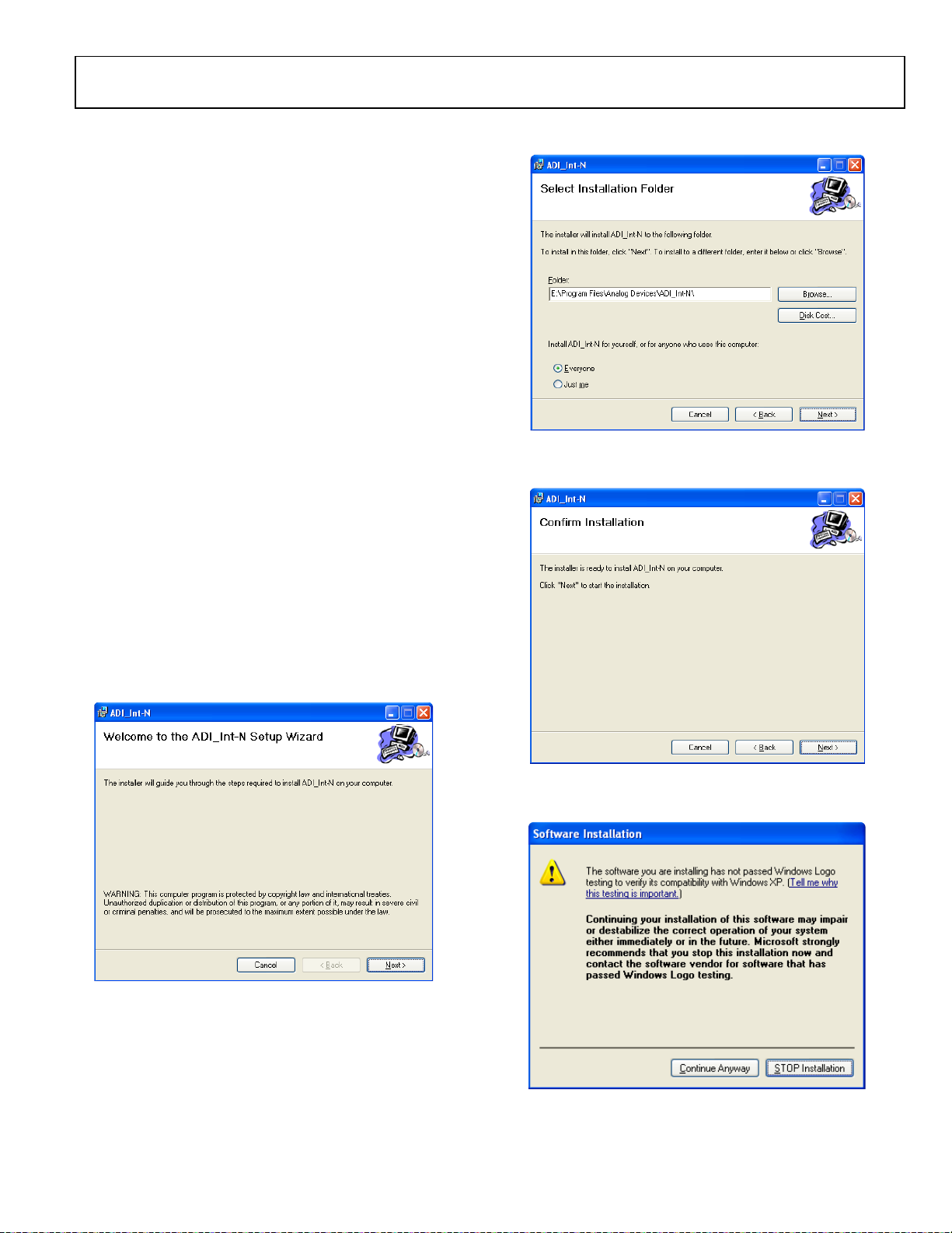
Figure 4. Windows XP Int-N Software Installation, Select Installation Folder
2. Choose an installation directory, and then click Next.
2. Plug the USB cable into the USB connector on the
evaluation board. If you are using Windows XP, follow the
steps in the Windows XP Driver Installation Guide section
(see Figure 13 to Figure 16).
On Windows Vista or Windows 7, the drivers install
automaticall y.
Windows XP Software Installation Guide
Figure 3. Windows XP Int-N Software Installation, Setup Wizard
1. Click Next.
Figure 5. Windows XP Int-N Software Installation, Confirm Installation
3. Click Next.
Figure 6. Windows XP Int-N Software Installation, Logo Testing
4. Click Continue Anyway.
Rev. A | Page 5 of 20
UG-160 Evaluation Board User Guide
09145-007
09145-008
09145-009
09145-010
09145-011
09145-012
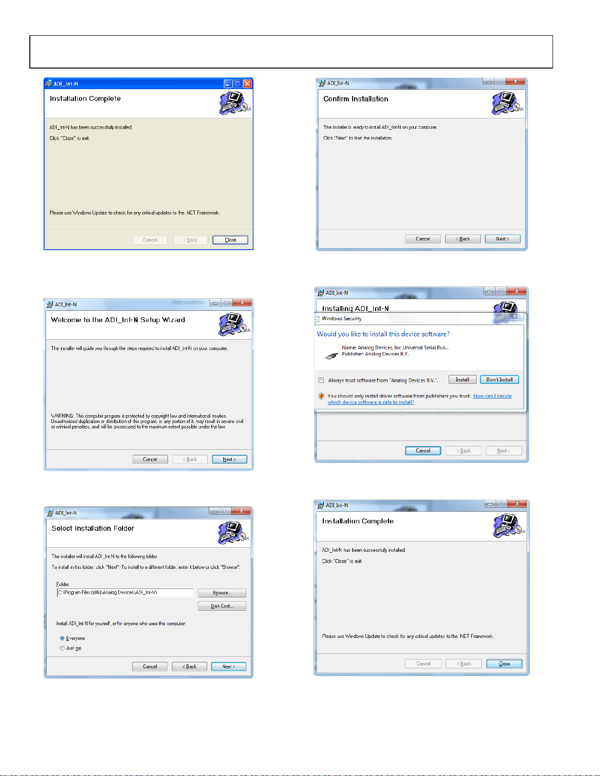
Figure 7. Windows XP Int-N Software Installation, Installation Complete
3. Click Close.
Windows Vista and Windows 7 Software Installation Guide
Figure 8. Windows Vista/7 Int-N Software Installation, Setup Wizard
1. Click Next.
Figure 10. Windows Vista /7 Int-N Software Installation, Confirm Installation
3. Click Next.
Figure 11. Windows Vista/7 Int-N Software Installation, Start Installation
4. Click Install.
Figure 9. Windows Vista/7 Int-N Software Installation, Select Installation
Folder
2. Choose an installation directory, and then click Next.
5. Click Close.
Rev. A | Page 6 of 20
Figure 12. Windows Vista/7 Int-N Software Installation, Installation Complete

Evaluation Board User Guide UG-160
09145-013
09145-014
09145-015
09145-016
Windows XP Driver Installation Guide
Figure 13. Windows XP USB Adapter Board Driver Installation, Found New
Hardware Wizard
1. Select the Yes, this time only option, and then click Next.
Figure 14. Windows XP USB Adapter Board Driver Installation, Installation
Options
2. Click Next.
Note that the window in Figure 14 may list Analog Devices
RFG.L Eval Board instead of ADF4xxx USB Adapter Board.
Figure 15. Windows XP USB Adapter Board Driver Installation, Logo Testing
3. Click Continue Anyway.
Figure 16. Windows XP USB Adapter Board Driver Installation, Complete
Installation
4. Click Finish.
Rev. A | Page 7 of 20

UG-160 Evaluation Board User Guide
09145-017
EVALUATION BOARD SOFTWARE
The control software for the EV-ADF4108EB1Z accompanies
the EV-ADF4108EB1Z on a CD. To install the software, see the
Software Installation section.
To run the software, click the Int-N v7 file on the desktop or in
the Start menu.
On the Select Device and Connection tab, choose your device
and your connection method, and then click Connect.
Confirm that “Analog Devices RFG.L Eval Board connected” is
displayed at the bottom left of the window (see Figure 17).
Otherwise, the software has no connection to the evaluation board.
Note that, when connecting the board, it takes about 5 to 10
seconds for the status label to change.
Under the File menu, the current settings can be saved to, and
loaded from, a text file.
Figure 17. Software Front Panel Display—Select Device and Connection
Rev. A | Page 8 of 20

Evaluation Board User Guide UG-160
09145-018
The Main Controls tab controls the PLL settings (see Figure 18).
Use the RF Settings section to control the output frequency. You
can type the desired output frequency in the RF VCO Output
Frequency text box (in MHz).
Use the Reference Frequency text box to set the correct
reference frequency and the reference frequency divider. The
default reference on the software window is at 100 MHz.
The Settings section lets you select general options available for
the PLL, including the charge pump current settings and phase
detector polarity. The EV-ADF4108EB1Z uses a charge pump
setting of 5 mA and a negative Phase Detector Polarity.
In the Registers tab, you can manually input the desired value
to be written to the registers.
In the Sweep and Hop tab, you can make the device sweep a
range of frequencies or hop between two set frequencies.
In the Latches/Registers section at the bottom of the window,
the values to be written to each register are displayed. If the
background on the text box is green, the value displayed is
different from the value actually on the device. Click Wr it e R
Counter Latch or Write N Counter Latch to write that value
to the device. To update all Latches in the correct order, click
Write all Latches.
Figure 18. Software Front Panel Display—Main Controls
Rev. A | Page 9 of 20

UG-160 Evaluation Board User Guide
09145-019
EVALUATION AND TEST
To evaluate and test the performance of the ADF4108, use the
following steps:
1. Install the Analog Devices Int-N software
2. Use ADIsimPLL to generate the loop filter component
values if a different loop filter is required.
3. Solder new filter components specified by ADIsimPLL.
4. Install the USB software drivers. Connect the evaluation
board to a PC using the supplied USB cable. Follow the
hardware driver installation procedure that appears.
5. Connect the USB connector to the EV-ADF4108EB1Z.
6. Connect a Reference signal to REFIN.
7. Connect a spectrum analyzer to EXT_VCOOUT OR
VCO/2.
8. Run the Int-N software.
9. Select the USB board and the ADF4108 device in the
Select Device and Connection tab of the software front
panel window.
10. On the Main Controls tab, set the VCO center frequency
(Figure 19 uses a 7.5 GHz VCO). Set the PFD frequency as
specified in ADIsimPLL, and program the Reference
frequency to match Reference connected to SMA
Connector REFIN (or the TCXO). See Figure 20 for the
suggested setup.
11. Measure the output spectrum. Figure 19 shows a 7.5 GHz
output.
Figure 19. Spectrum Analyzer Display
Rev. A | Page 10 of 20

Evaluation Board User Guide UG-160
SPECTRUM
ANALYZER
PC
EXTERNAL DC
GND
EXTERNAL DC
SUPPLY
TCXO
VCO
ACTIVE LOOP
FILTER
PLL
POWER
LED
USB INTERFACE
REFERENCE IN
(REFERENCE O UT)
PLL
LOCK
CPOUT
AGND
+15V
VTUNE VVCO
VCO/2
EXT_VCOOUT
DETECT
LED
POWER
SUPPLIES
SIGNAL
GENERATOR
POWER
SUPPLIES
09145-020
Figure 20. Typical Evaluation Setup
Rev. A | Page 11 of 20

UG-160 Evaluation Board User Guide
09145-021
EVALUATION BOARD SCHEMATICS AND ARTWORK
Figure 21. Evaluation Board Schematic (Page 1)
Rev. A | Page 12 of 20

Evaluation Board User Guide UG-160
09145-022
Figure 22. Evaluation Board Schematic (Page 2)
Rev. A | Page 13 of 20

UG-160 Evaluation Board User Guide
09145-023
Figure 23. Evaluation Board Schematic (Page 3)
Rev. A | Page 14 of 20

Evaluation Board User Guide UG-160
09145-024
Figure 24. Evaluation Board Schematic (Page 4)
Rev. A | Page 15 of 20

UG-160 Evaluation Board User Guide
09145-025
09145-026
Figure 25. Layer 1 (Component Side)
Figure 26. Layer 2 (Ground Plane)
Rev. A | Page 16 of 20

Evaluation Board User Guide UG-160
09145-027
09145-028
Figure 27. Layer 3 (Power/Ground Plane)
Figure 28. Layer 4 (Solder Side)
Rev. A | Page 17 of 20

UG-160 Evaluation Board User Guide
C26, C27
NPO SMD ceramic capacitor, 0603, 50 V, 10 pF
ORDERING INFORMATION
BILL OF MATERIALS
Table 1.
Reference Designator Part Description
+5V, +15V, 3V3_USB,1 5V_USB,1 AVD D,1
CE,1 CLK,1 DATA,1 DVDD,1 LE,1
MUXOUT,
AGND, AGND1 Black test point
C1 Capacitor, 0603, 50 V, 680 pF, COG/NPO
C2 Capacitor, 0603, X7R, 50 V, 68 nF
C3 Capacitor, 0603, X7R, 50 V, 1.8 nF
C4 Capacitor, 0603, X7R, 50 V, 2.7 nF
C5, C8, C19, C21, C22, C28, C30, C32,
C33
C6, C7, C20, C42, C44, C45, C46, C53,
C54, C55, C57, C58, C59, C60
C9 X5R ceramic capacitor, 0402, 6.3 V, 0.22 µF
C10, C16, C18, C24, C38, C41, C52, C56 NP0 ceramic capacitor, 0402, 50 V, 10 pF
C11, C12, C49 NP0 ceramic capacitor, 0603, 50 V, 1 nF
C13, C48, C51 Tantalum capacitor (TAJ-A Case), RTAJ _A, 6.3 V, 22 µF
C14, C25, C29, C39 COG ceramic capacitor, 0402, 50 V, 100 pF
C15, C31, C47, C50 Capacitor, X5R, 0805, 1.0 μF, 50 V
C17 Capacitor, X5R 0805, 10 V, 10 μF, 10%
C23, C37 X5R ceramic capacitor, 0402, 25 V, 0.1 µF
1
OPBIAS,1 T1,1 T2,1 RIG, VP1
Red test point
Capacitor, 0603, 1 μF, 10 V, X5R
X7R ceramic capacitor, 0402,16 V, 0.1 µF
C34 Multilayer ceramic capacitor, 0603, 10 pF
C35 X5R ceramic capacitor, 0805, 6.3 V, 22 µF
C36 Capacitor, CASE B, 100 μF, 6.3 V, RTA J_B
C40 Capacitor, 0402, 100 pF, 50 V, NP0
C431 Capacitor, RTAJ_D
CPOUT, REFIN, VTUNE, VVCO Conn jack end launch PC gold SMA
D1, D4 LED, green
D2 Diode, standard, 1 A, 50 V
D3 LED, red
EXT_VCOOUT, VCO/2 High frequency SMA end launch connector—142-0761-801
GND Black 4mm banana socket
L1 Ferrite bead, 470 Ω @ 100MHz
L2 Inductor, SMT Power EPL2014 Series, 4.7 µH
R1 Resistor, 0603, 390 Ω
R2 Resistor, 0603, 510 Ω
R3, R28, R38 Resistor, 0603, 1 kΩ
R4 Resistor, 0603, 5.1 kΩ
R5, R10, R21, R24, R26, R27, R29, R32,
R35, R37, R43, R46, R48, R52, R53, R56,
R57, R58, R60, R61
R6,1 R31,1 R34,1 R55,1 R671 Resistor, 0402
R7, R59, R62 Resistor, 0603, 10 kΩ
R8, R23 Resistor, 0603, 47 kΩ
R9, R18, R19 Resistor, 0603, 330 Ω
R11,1 R13,1 R14,1 R15,1 R17,1 R22,1 R25,1
1
R30,
R33,1 R36,1 R42,1 R47,1 R51,1
1
R54,
R631
Resistor, 0603, 0 Ω
Resistor, 0603
Rev. A | Page 18 of 20

Evaluation Board User Guide UG-160
R16, R64, R65,
Resistor, 0402, 0 Ω
R40
Resistor, 0603, 140 kΩ
U7
64 K, I2C Serial EEPROM
Reference Designator Part Description
R12 Resistor, 0603, 49.9 Ω
R20 Resistor, 0603, 10 Ω
R39 R49, R50, Resistor, 0603, 2.2 kΩ
R41 Resistor, 0603, 78.7 kΩ
R44, R45, Resistor, 0603, 100 kΩ
R66 Resistor, 0402, 0.33 Ω
U1 ADF4108, PLL frequency synthesizer
U2, U3, U10, U13 ADP150AUJZ-3.0, 3.0 V linear regulator
U4 OP184, single op amp
U5 ADP3334, adjustable LDO regulator
U6 USB microcontroller
U8 ADP7104ARDZ-5.0, linear regulator
U9 Power divider, 6 dB, 1 W, 0603 SMD
U11 VCO, dual output and divide by 2 prescaler
U12 Attenuator, 3 dB, 50 Ω, 0805 SMD
VSUPPLY Red 4 mm banana socket
Y11 TX-500 temperature compensated crystal oscillator, 100.0 MHz
Y2 SMD crystal, 24.0 MHz
1
Do not insert.
RELATED LINKS
ADF4108 Product Page, PLL Frequency Synthesizer
ADP150AUJZ Product Page, Ultralow Noise, 150 mA CMOS Linear Regulator
OP184 Product Page, Single-Supply Rail-to-Rail Input/Output Operational Amplifier
ADP3334 Product Page, High Accuracy Low IQ, 500 mA anyCAP® Adjustable Low Dropout Regulator
ADP7104ARDZ Product Page, 20 V, 500 mA, Low Noise, CMOS LDO
Rev. A | Page 19 of 20

UG-160 Evaluation Board User Guide
AR PURPOSE OR NONINFRINGEMENT OF INTELLECTUAL
NOTES
I2C refers to a communications protocol originally developed by Philips Semiconductors (now NXP Semiconductors).
EEB Caution
EEB (electrostatic discharge) sensitive device. Charged devices and circuit boards can discharge without detection. Although this product features patented or proprietary protection
circuitry, damage may occur on devices subjected to high e nergy EEB. Therefore, proper EEB precautions should be taken to avoid performance degradation or loss of functionality.
Legal Terms and Conditions
By using the evaluation board discussed herein (together with any tools, components documentation or support materials, the “Evaluation Boa rd”), you are agreeing to be bound by the term s and conditions
set forth below (“Agreement”) unless you have purchased the Evaluation Board, in which case the Analog Devices Standard Terms and Conditions of Sale shal l gover n. Do not u se t he Evaluation Board until you
have read and agreed to the Agreement. Your use of the Evaluation Board shall signify your acceptance of the Agreement. This Agreement is made by and between you (“Customer”) and Analog Devices, Inc.
(“ADI”), with its principal place of business at One Technology Way, Norwood, MA 02062, USA. Subject to the terms and conditions of the Agreement, ADI hereby grants to Customer a free, limited, personal,
temporary, non-exclusive, non-sublicensable, non-transferable license to use the Evaluation Board FOR EVALUATION PURPOSES ONLY. Customer understands and agrees that the Evaluation Board is provided
for the sole and exclusive purpose referenced above, and agrees not to use the Evaluation Board for any other purpose. Further more, the license granted is expressly made subject to the following additional
limitations: Customer shall not (i) rent, lease, display, sell, transfer, assign, sublicense, or distribute the Evaluation Board; and (ii) permit any Third Party to access the Evaluation Board. As used herein, the term
“Third Party ” includes any entity other than ADI, Customer, their employees, affiliates and in-house consultants. The Evaluation Board is NOT sold to Customer; all rights not expressly granted herein, including
ownership of the Evaluation Board, are reserved by ADI. CONFIDENTIALIT Y. This Agreement and the Evaluation Board shal l all be considered the confidential and proprieta ry information of AD I. Customer may
not disclose or transfer any portion of the Evaluation Board to any other party for any reason. Upon discontinuation of use of the Evaluation Board or ter mination of this Agreement, Customer agrees to
promptly return the Evaluation Board to ADI. ADDITIONAL RESTRICTIONS. Customer may not disassemble, decompile or reverse engineer chips on the Evaluation Board. Customer shall inform ADI of any
occurred damages or any modifications or alterations it makes to the Evaluation Board, including but not limited to soldering or any other activity that affects the material content of the Evaluation Board.
Modifications to the Evaluation Board must comply with applicable law, including but not limited to the RoHS Directi ve. TERMINATI ON. ADI may terminate this Agreement at any time upon giving written notice
to Customer. Customer agrees to return to ADI the Evaluation Board at that time. LIMITATION OF LIABILITY. THE EVALUATION BOARD PROVIDED HEREUNDER IS PROVIDED “AS IS” AND ADI MAKES NO
WARRANTIES OR REP RESENTATIONS OF ANY KIND WIT H RESPECT TO IT. ADI SPECIFICALLY DISCLAIMS ANY REPRESENTATI ONS, ENDORSEMENTS, GUARANTEES, OR WAR RANTIES, EXPRESS OR IMPLIED, RELATED
TO THE EVALUATION BOARD INCLUDING, BUT NOT LIMITED TO, THE IMPLIED WARRANTY OF MERCHANTABILITY, TITLE, FITNESS FOR A PARTICUL
PROPERTY RIGHTS. IN NO EVENT WILL ADI AND ITS LICENSORS BE LIABLE FOR ANY INCIDENTAL, SPECIAL, INDIRECT, OR CONSEQUENTIAL DAMAGES RESULTING FROM CUSTOMER’S POSSESSION OR USE OF
THE EVALUATION BOARD, INCLUDING B UT NOT LIMITED TO LOST PRO FITS, DELAY COSTS, LABOR COST S OR LOSS OF GOODW ILL. ADI’S TOTAL LIABILITY FR OM ANY AND ALL CAUSES SHALL BE LIMITED TO THE
AMOUNT OF ONE HUNDRED US DOLLARS ($100.00). EXPORT. Customer agrees that it will not directly or indirectly export the Evaluation Board to another country, and that it will comply with all applicable
United States federal laws and regulations relating to exports. GOVERNING LAW. This Agreement shall be governed by and construed in accordance with the substantive laws of the Commonwealth of
Massachusetts (excluding conflict of law rules). Any legal action re garding this Agreement will b e heard in the state or fe deral courts having j uriEBiction in Suffolk County, Massachusetts, and Customer hereby
submits to the personal juriEBiction and venue of such courts. The United Nations Convention on Contracts for the Intern ational Sale of Goo ds shall not ap ply to this Agreement and is expressly disclaimed.
©2010–2012 Analog Devices, Inc. All rights reserved. Trademarks and
registered trademarks are the property of their respective owners.
UG09145-0-3/12(A)
Rev. A | Page 20 of 20
 Loading...