

Evaluation Board User Guide
BPF
ADL5523 ADL5523
ADL5382
GAIN
CONTROL
BPF
LPF
RF
LO
ADF4360
DA
AD9262
LPF
90°
0°
ADC
ADC
DB
122.88MHz
AD9516-0
DDC
DCO
08471-001
UG-051
One Technology Way • P.O. Box 9106 • Norwood, MA 02062-9106, U.S.A. • Tel: 781.329.4700 • Fax: 781.461.3113 • www.analog.com
Evaluating the AD9262, 16-Bit, Dual Continuous Time Sigma Delta ADC and
Demonstrating Direct Conversion
EVALUATION BOARD DESCRIPTION
The AD9262 evaluation board serves two purposes: as an
evaluation platform for the 16-bit dual continuous time sigma
delta ADC and as a direct conversion demonstration platform.
Tabl e 1 lists the product features of all the Analog Devices, Inc.,
components in the demonstrator.
The AD9262 is a dual, 16-bit analog-to-digital converter (ADC)
based on a continuous time sigma-delta (Σ-Δ) architecture that
achieves 86 dB of dynamic range over a 10 MHz real or 20 MHz
complex bandwidth. The integrated features and characteristics
unique to the continuous time Σ-Δ architecture significantly
simplify its use and minimize the need for external components.
This evaluation board supports the AD9262 family of products,
including the AD9262BCPZ-10, AD9262BCPZ-5, and
AD9262BCPZ.
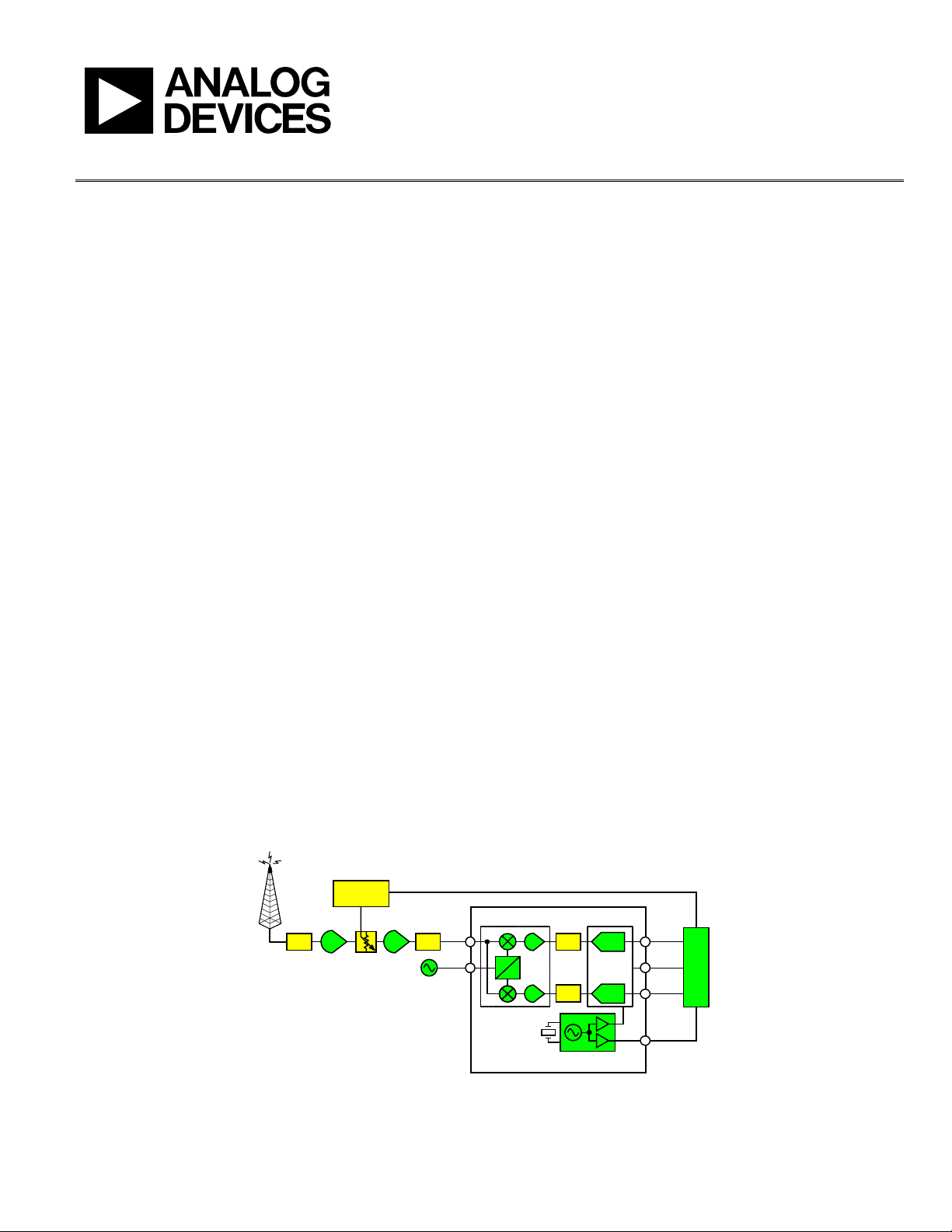
Direct conversion architectures, as shown in Figure 1, use a
single frequency translation step to convert the RF channel
directly to baseband without any intermediate frequency stages.
The frequency translation in this direct conversion demonstrator
is accomplished by the ADL5382, which is a quadrature demodul ator. The ADL5382 covers the frequency range between 700
MHz and 2.7 GHz.
The AD9262 has passive inputs, therefore allowing the ADL5382
to directly drive the ADC. The AD9262 does not require a filter
preceding the converter because the continuous time sigmadelta architecture possesses inherent antialiasing capabilities.
Therefore, minimal or no filtering is required between the
demodulator and the ADC. A prototype area for a fourth order
filter is provided in which additional filtering can be tested.
To achieve optimal performance from the AD9262, a low jitter
differential clock is necessary, and the AD9516 family of parts
offers superior clock performance. The AD9516 and a crystal
oscillator footprint are included on the evaluation board. In
addition to providing a clock option to the ADC, outputs from
the AD9516 can be used to drive other external capture devices.
The ADR130B offers the option of using an external 0.5 V band
gap reference voltage for the AD9262. The ADP3339 provides a
quiet and reliable voltage source to each of the ADI components.
In addition to offering system-level evaluation of the direct
conversion architecture, the evaluation board offers the flexibility
of isolating the AD9262 from the surrounding components,
enabling a detailed evaluation of only the AD9262. The ADC
inputs can be disconnected from the ADL5382 and be driven
with an external source. The analog inputs of the AD9262 can
be driven from either a differential transformer or the ADA4937,
which is a very low noise, high linearity differential amplifier.
Complementing the AD9262 evaluation board are additional
hardware and software to capture and process the digital data
from the output of the ADC. The AD9262 can only be
evaluated using the HSC-ADC-E VA LC Z high speed ADC data
capture card in conjunction with the VisualAnalog
capture and analysis software. The SPIController
TM
data
TM
software is
used to read and write to the AD9262.
See the last page for an important warning and disclaimers. Rev. 0 | Page 1 of 24
Figure 1. Direct Conversion Receiver Block Diagram

UG-051 Evaluation Board User Guide
TABLE OF CONTENTS
Evaluation Board Description ......................................................... 1
Revision History ............................................................................... 2
Product Features ............................................................................... 3
Getting Started .................................................................................. 4
Configuring the Evaluation Board ................................................. 5
Power Supply ................................................................................. 5
Clock .............................................................................................. 5
Receiver Input Configuration ..................................................... 5
ADC Only Input Configuration ................................................. 5
Differential Transformer Path .................................................... 6
ADC Driver Path .......................................................................... 6
Supporting Hardware and Software ............................................... 7
REVISION HISTORY
1/10—Revision 0: Initial Version
Software ..........................................................................................7
Hardware ........................................................................................7
AD9262 SPI Controller ................................................................7
AD9516 SPI Controller ................................................................7
AD9516 Register Settings .............................................................8
VisualAnalog Overview ................................................................9
Schematics ....................................................................................... 10
Layout ............................................................................................... 15
Ordering Information .................................................................... 19
Bill of Materials ........................................................................... 19
ESD Caution................................................................................ 24
Rev. 0 | Page 2 of 24

Evaluation Board User Guide UG-051
PRODUCT FEATURES
Table 1.
AD9262 ADL5382 AD9516-0
SNR: 82.5 dB (84.5 dBFS) to
10 MHz input
SFDR: 87 dBc to 10 MHz input
Noise figure: 15 dB
Input impedance: 1 kΩ
Power: 675 mW
1.8 V analog supply operation
1.8 V to 3.3 V output supply
Selectable bandwidth
2.5 MHz/5 MHz/10 MHz real
5 MHz/10 MHz/20 MHz complex
Output data rate: 30 MSPS to
160 MSPS
Integrated decimation filters
Integrated sample rate converter
On-chip PLL clock multiplier
I/Q demodulator
Operating RF frequency: 700 MHz to
2700 MHz
IIP3 + 30 dBm
IIP2 + 60 dBm
Input P1dB + 13dBm
NF 14 dB @ 900 MHz
Voltage conversion gain: 5 dB
Quadrature demodulation accuracy
Phase accuracy <0.5°
Amplitude balance <0.25 dB
LO input: −10 dBm to +5 dBm
Demodulation bandwidth: ~500 MHz
I/Q drive 2 V
into 200 Ω
PEAK
Programmable power consumption
On-chip voltage reference
Offset binary, gray code, or twos
complement data format
Serial control interface (SPI)
ADR130B ADP3339 ADA4937
Initial accuracy
A grade: ±0.70% (maximum)
B grade: ±0.35% (maximum)
Maximum temperature coefficient
A grade: 50 ppm/°C
B grade: 25 ppm/°C
: 50 nF to 10 μF
C
LOAD
Output current: +4 mA/−2 mA
Low operating current: 80 μA
(typical)
Output noise: 6 μV p-p @ 1.0 V
output
Input range: 2.0 V to 18 V
Temperature range: −40°C to
High accuracy over line and load: ±0.9% @
25°C, ±1.5% over temperature
Ultralow dropout voltage: 230 mV (typical)
@ 1.5 A
Requires only C
= 1.0 μF for stability
O
anyCAP® regulators: stable with any type
of capacitor (including MLCC)
Current and thermal limiting
Low noise
2.8. V to 6 V supply range
−40°C to +85°C ambient temperature
range
SOT-223 package
+125°C
Tiny Pb-free TSOT package
Low phase noise, phase-locked loop
On-chip VCO tunes from 2.55 GHz to 2.95 GHz
External VCO/VCXO to 2.4 GHz (optional)
One differential or two single-ended reference
inputs
Reference monitoring capability
Auto and manual reference switchover/holdover
modes
Autorecover from holdover
Accepts references to 250 MHz
Programmable delays in path to PFD
Digital or analog lock detect, selectable
Three pairs of 1.6 GHz LVPECL outputs
Each pair shares one to 32 dividers with coarse
phase delay
Additive output jitter: 225 fs rms
Channel-to-channel skew paired outputs: <10 ps
Two pairs of 800 MHz LVDS clock outputs
Each pair shares two cascaded one-to-32 dividers
with coarse phase delay
Additive output jitter: 275 fs rms
Fine delay adjust (ΔT) on each LVDS output
Eight 250 MHz CMOS outputs (two per LVDS output)
Automatic synchronization of all outputs on power-up
Manual synchronization of outputs as needed
Serial control port
64-lead LFCSP
Extremely low harmonic distortion
−112 dBc HD2 @ 10 MHz
−79 dBc HD2 @ 70 MHz
−70 dBc HD2 @ 10 MHz
−102 dBc HD3 @ 10 MHz
−91 dBc HD3 @ 70 MHz
−84 dBc HD3 @ 100 MHz
Low input voltage noise: 2.2 nV/√Hz
High speed
−3 dB bandwidth of 1.0 GHz, G = 1
Slew rate: 6000 V/μs, 25% to 75%
dB gain flatness to 200 MHz
Fast overdrive recovery of 1 ns
1 mV typical offset voltage
Externally adjustable gain
Differential-to-differential or single-ended–to-
differential operation
Adjustable output common-mode voltage
Single-supply operation: 3.3 V to 5 V
Pb-free, 3 mm × 3 mm 16-lead LFCSP
Rev. 0 | Page 3 of 24
UG-051 Evaluation Board User Guide
08471-002
08471-003
USB
PWR: 6V
PWR: 5V
CLOCK
LO
INPUT
RF
INPUT
08471-004
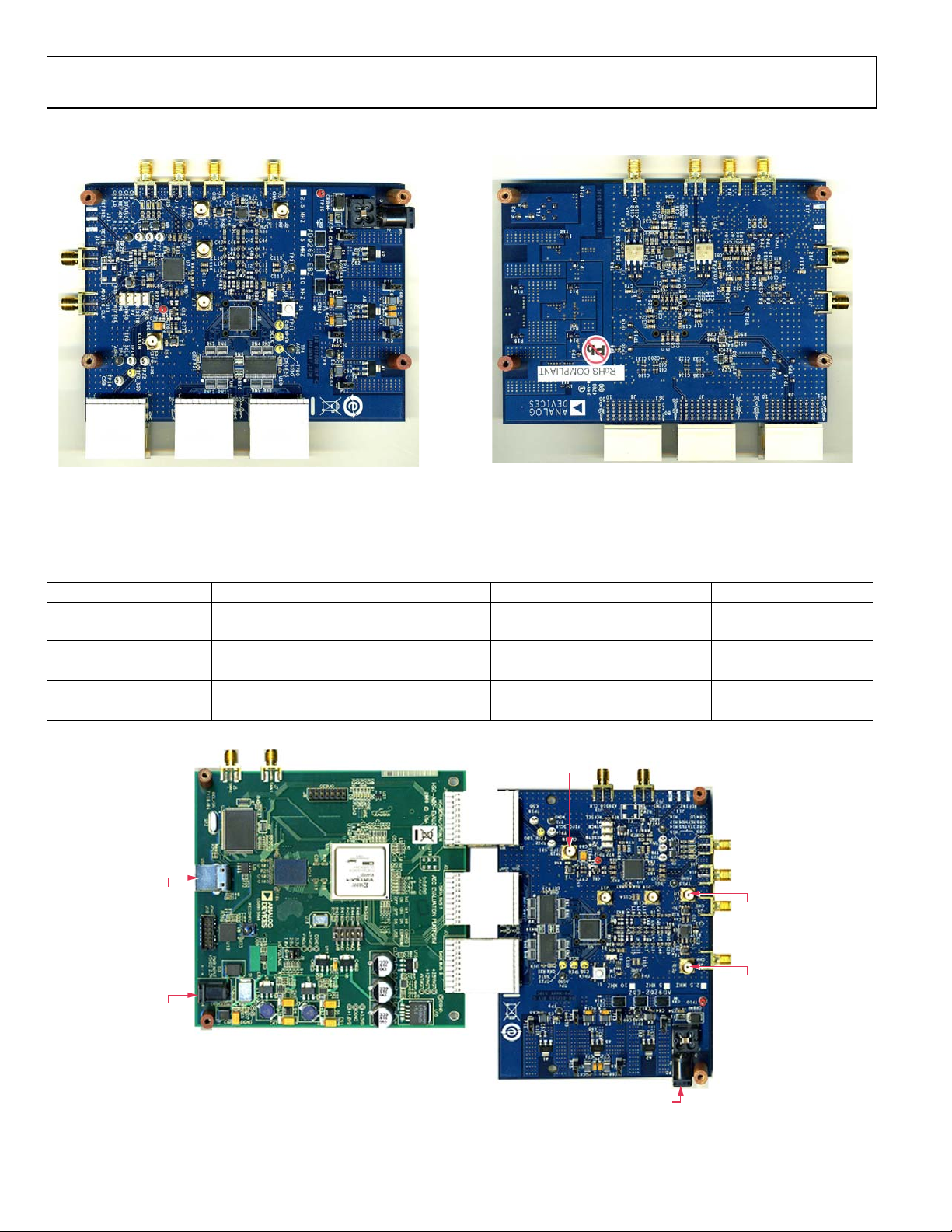
GETTING STARTED
Figure 2. Evaluation Board Front
Figure 3. Evaluation Board Back
The default configuration of the AD9262 evaluation board allows a quick and easy start to evaluating the direct conversion receiver
subsystem. The default configuration interfaces the ADL5382 directly with the AD9262. Tab l e 2 and Figure 4 show the hardware required
to start the evaluation.
Table 2. Quick Start Hardware Requirements
Name Board Value Reference Designator
Power AD9262EBZ +6 V P2
HSC-ADC-EVALCZ +5 V
Clock AD9262EBZ 640 MHz J3
RF Input AD9262EBZ 700 MHz to 2.7 GHz J2
LO Input AD9262EBZ −10 dBm to +5 dBm J1
USB HSC-ADC-EVALCZ
Figure 4. Quick Start Configuration
Rev. 0 | Page 4 of 24
Evaluation Board User Guide UG-051
0Ω
R13
576Ω
R19
0Ω
R11
280Ω
C107
1000pF
C108
560pF
C31
15,000pF
LF
CP
BYPASS_LDO
08471-005
C48
L3
L7
L11
L15
L4
L8 L12
L16
C50
08471-006
CONFIGURING THE EVALUATION BOARD
POWER SUPPLY
Power is provided to the evaluation board by a single +6.0 V
source applied to P2. The power source is regulated down to the
appropriate levels by the ADP3339 voltage regulators. Tab le 3
shows the necessary voltage levels for each component.
Table 3. Component Power Supplies
Component Power Supply
AD9262 1.8 V
ADL5382 5.0 V
AD9516-0 3.3 V
CLOCK
The AD9262 evaluation board offers many clocking options:
a high frequency external clock can be applied directly to the
ADC; the AD9516-0 LVPECL or CMOS clock can be used; and
a low frequency clock, in conjunction with the integrated PLL
from either the AD9516-0 or AD9262, can provide the necessary
input clock frequency. The default clock option is configured
for an external clock rate of 640 MHz.
The AD9262 evaluation board includes the footprint for a Val p ey
Fisher VFAC3 crystal oscillator. The crystal oscillator can serve
as the reference clock to the AD9516-0, and the chip’s internal
PLL can be used to generate a clock closest to the desired frequency for the ADC. For example, a 122.88 MHz reference
produces a VCO frequency of 2.580 GHz. The AD9516-0
possesses an integrated VCO. The VCO frequency is further
divided down by 4 to generate an output clock of 645 MHz,
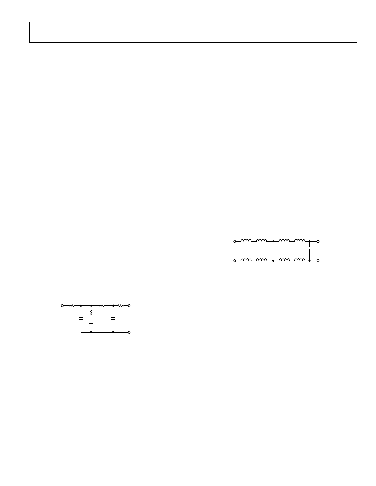
which serves as the input clock to the ADC. To optimize the
AD9516-0 for this particular frequency, the loop filter must be
configured as shown in Figure 5.
Figure 5. AD9516-0 Loop Filter
If the user chooses an alternative crystal oscillator frequency,
the loop filter components must be configured appropriately.
Some common crystal oscillators and the corresponding loop
filter components are shown in Tab l e 4. Refer to the ADIsimCLK
software for design guidance.
To configure the evaluation board for either the external clock
source or the AD9516-0 requires modifying the JP5 and JP6
solder jumpers. The AD9262 sets the common-mode level of
the input clock to 450 mV; therefore, the clock source should be
ac-coupled to the ADC input clock pins. Use the AD9516-0
software to configure the chip to the appropriate divide ratios.
RECEIVER INPUT CONFIGURATION
The default configuration uses the complex output signals of
the I/Q demodulator as the input signals to the AD9262. In this
configuration, the RF input signal should be applied to J2 and
the LO signal to J1. The RF input range of the ADL5382 is
limited to between 700 MHz and 2.7 GHz. The single-ended
RF and LO signals are converted to differential signals using the
RF transformers, T2 and T1. The resulting output signals of the
demodulator are differential I and Q signals that can be directly
applied to the resistive inputs of the AD9262, and no driver
amplifiers are required.
Between the output of the ADL5382 and the input to the
AD9262 are space holders for a fourth order filter (see Figure 6).
This filter may or may not be necessary depending on the
application.
Figure 6. Fourth Order Filter
ADC ONLY INPUT CONFIGURATION
In addition to using the ADL5382 as an input source to the
ADC, the AD9262 can be driven with an external source through
either the ADA4937 or a differential transformer.
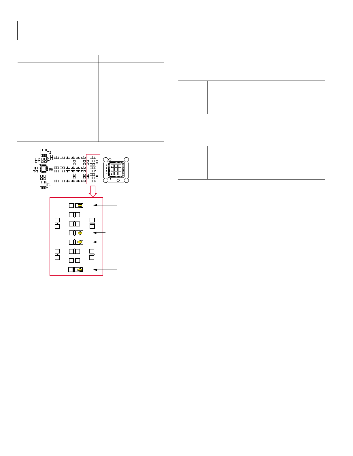
To configure the evaluation board for an external source, follow
the hardware configuration shown in Ta b le 5. The SMA
connectors, labeled J5 and J4, correspond to the input signals to
Channel A and Channel B, respectively, of the AD9262.
Additionally, short TP17, TP23, TP2, and TP24 to the appropriate
pads to route the external signals to the input pins of the AD9262
(see Figure 7). This configuration requires careful attention to
ensure that the output signals of the ADL5382 are disconnected
and only the signals from the transformer or ADA4937 are
routed to the ADC.
Table 4. AD9516-0 CLK Configuration
Crystal
(MHz)
134.4 1000 pF 232 Ω 18,000 pF 486 Ω 680 pF
122.88 1000 pF 280 Ω 15,000 pF 576 Ω 560 pF
39.3216 1500 pF 221 Ω 22,000 pF 453 Ω 680 pF
C107 R11 C31 R13 C108
Loop Filter
AD9262
CLK
MHz
672
MHz
645.12
MHz
648.8
Rev. 0 | Page 5 of 24
UG-051 Evaluation Board User Guide
4 L
L L
L 1
4 6
R37
3
C43
C42
R38 R37
R33
R40
R34
R35
R36
R41
R42
R39
TP24
TP2
TP23
TP17
AD9262
REMOVE R39 T O R42.
SHORT TP 24, TP2,
TP23, AND TP 17 TO
THE CLOSEST PAD.
08471-007
Table 5. External ADC Input Configuration
Connector Setting Notes
J4, J5 J4: Channel B
J5: Channel A
R33 to 42 DNP
Disconnect ADL5382
outputs from the AD9262
TP17
Short to the closest
Connect A+ path
pad on R40
TP23
Short to the closest
Connect A− path
pad on R39
TP2
Short to the closest
Connect B+ path
pad on R42
TP24
Short to the closest
Connect B− path
pad on R41
DIFFERENTIAL TRANSFORMER PATH
To activate the differential transformer path, configure the
jumpers as shown in Tabl e 6.
Table 6. Differential Transformer Configuration
Jumper Setting Notes
JP1, JP2
JP3 to JP6
Short Position 1
and Position2
Short Position 2
and Position 3
Configure SMA connectors for
transformer inputs
Configure differential transformer outputs to ADC inputs
ADC DRIVER PATH
Set the jumpers as shown in Table 7.
Table 7. ADA4937 Configuration
Jumper Setting Notes
JP1, JP2
JP3 to JP6
Short Position 2
and Position 3
Short Position 1
and Position 2
Configure SMA connectors for
ADA4937 inputs
Configure outputs from the
ADA4937 to ADC inputs
Figure 7. External ADC Jumper Settings
Rev. 0 | Page 6 of 24
Evaluation Board User Guide UG-051
08471-017
08471-018
SUPPORTING HARDWARE AND SOFTWARE
The AD9262 can only be evaluated using the HSC-ADCEVALCZ high speed ADC data capture card in conjunction
with the VisualAnalog data capture and analysis software.
The SPIController software is used to configure the AD9262
and the AD9516 to the appropriate register settings.
SOFTWARE
Manuals for VisualAnalog, the SPIController software, and
the HSC-ADC-EVALCZ data capture hardware are included
on the CD in the evaluation board package. It is recommended
that the software be installed before connecting the hardware.
VisualAnalog relies on the Microsoft .NET framework version 2,
which is also included on the package CD. The .NET framework should be installed before installing VisualAnalog. The
SPIController software should also be installed.
HARDWARE
The AD9262 evaluation board and the HSC-ADC-EVA LC Z
data capture card are powered from a wall-connected switching
power supply. The switching power supplies have different
output voltages. Connect the 6 V power supply to the AD9262
evaluation board and the 5 V power supply to the HSC-ADCEVALCZ data capture board. With the HSC-ADC-EVA L CZ
data capture board powered on and the VisualAnalog software
installed, connect the USB cable to the PC and follow all the
Found new hardware prompts, using the default driver each time.
AD9516 SPI CONTROLLER
Open another instance of the SPIController for control of the
AD9516. If a box titled Read Test Failure appears, click Ignore
to open the SPIController. This error occurs because the
software has not been configured correctly to read from the
chip. Use the following procedure to appropriately configure the
SPIController to read and write to the AD9516:
1. From the File menu, select CfgOpen; then select
AD9516spiengR03.cfg.
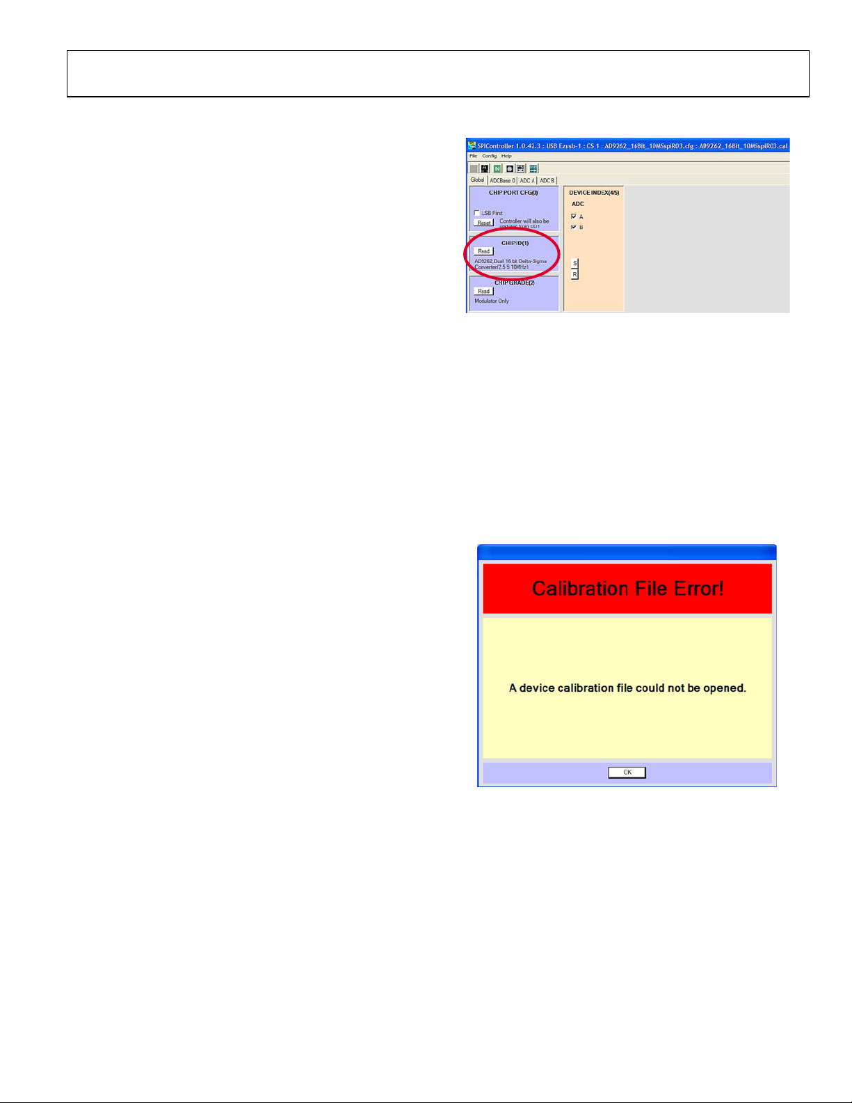
2. When a Calibration File Error! message appears as shown
in Figure 9, click OK.
Figure 8. AD9262 SPIController
AD9262 SPI CONTROLLER
Upon successful software installation and hardware setup, start
the AD9262 SPIController software. By default, the software
recognizes the AD9262 evaluation board and loads the correct
SPIController profile. If it does not, point the software to the
following file: AD9262_16Bit_10MSspiR03.cfg.
The AD9262 SPIController has four tabs. When correctly
configured, a message appears on the CHIP ID subpane
reporting that the AD9262 is interfaced (see Figure 8).
Figure 9.
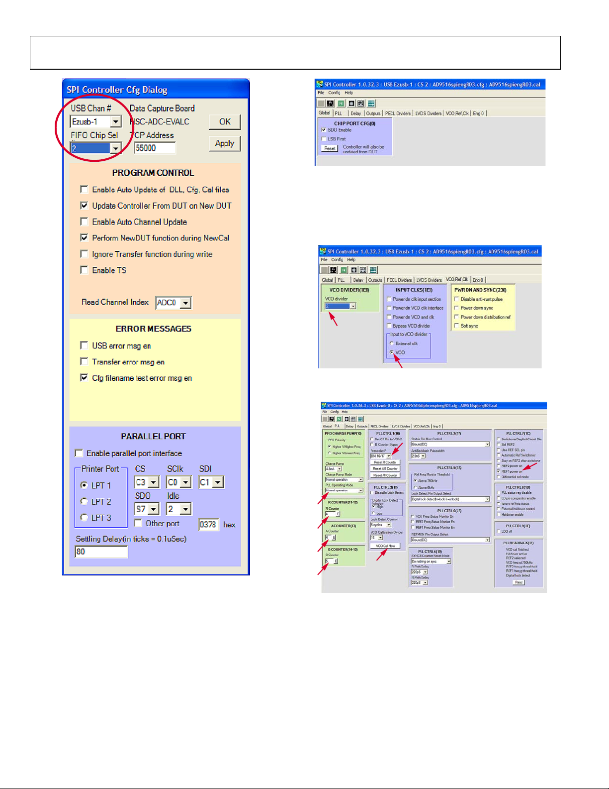
3. Select Config and then Controller Dialog and make sure
that FIFO Chip Sel is set to 2 and that USB Chan # is set
to the same value as the AD9262 SPIController Cfg dialog
(see Figure 10).
Rev. 0 | Page 7 of 24
UG-051 Evaluation Board User Guide
08471-019
08471-020
2
1
08471-021
3
4
5
6
9
7
8
08471-022
Figure 11. AD9516 Configuration
The AD9516 register settings depend on the particular clock
option chosen. Ta b l e 8 provides a list of register settings for
some common crystal oscillators. The configuration shown in
Figure 12 and Figure 13 is for the 122.88 MHz crystal oscillator.
Figure 12. VCO and Clock Configuration for the 122.88 MHz Crystal Oscillator
Figure 10.
AD9516 REGISTER SETTINGS
Figure 13. PLL Configuration for the 122.88 MHz Crystal Oscillator
The SPIController uses a 4-wire interface; therefore, the
AD9516 must be configured for this interface before any further
writes can take effect. To configure the AD9516, check the SDO
Enable bit, as shown in Figure 11.
Rev. 0 | Page 8 of 24

Evaluation Board User Guide UG-051
08471-023
Table 8. AD9516 Register Settings
Register 134.4 MHz 122.88 MHz 39.3216 MHz
VCO 2.688 GHz 2.580 GHz 2.595 GHz
R Divider 4 4 1
A/B Counter 0/5 4/5 2/4
Prescaler 16/17 16/17 16/17
Output CLK 672 MHz 645.12 MHz 648.81 MHz
VisualAnalog OVERVIEW
Open VisualAnalog and choose a canvas from the AD9262
folder (see Figure 14).
Figure 14. VisualAnalog Canvas
Rev. 0 | Page 9 of 24

UG-051 Evaluation Board User Guide
08471-008
ADA4937-2: +5V
AD9516-0: +3.3V
AD9262
ADL5382: +5V
DVDD: +1.8V
CVDD: +1.8V
AVDD: +1.8V
POWER SUPPLY
DRVDD: +1.8V
+6V
R47
C70
C69
C68
C67
C58C65
C62
C55
C64
C63
C53
21
E6
21
E7
21
E8
21
E5
21
E3
21
E4
P14
P13
P16
P15
P11
P12
2
4
3
1
A1
3
6
5
4
21
FL1
3
2
1
P2
C54
A
C
CR8
2
1
F1
1
TP9
AC
CR9
1
TP11
1
TP10
N
P
C74
N
P
C73
N
P
C72
2
431
A5
N
P
C71
C128
A C
CR14
A C
CR13
2
431
A2
AVDD
BERG69157-102
PJ-102A
0
BERG69157-102
ADP3339AKCZ-3.3-RL
AD9516_+3P3V
115OHMS
BERG69157-102
115OHMS
4.7UF
1UF
1UF
ADP3339AKCZ-1.8-RL
CVDD
1UF
115OHMS
4.7UF
DRVDD
DVDD
1UF
1UF
115OHMS
4.7UF
ADP3339AKCZ-5-RL
1UF
115OHMS
RED
BLK
1UF1UF
S2A-LT S2A-LT
S2A-LT
1.1A
1UF
1UF
115OHMS
1UF
1UF
+5V
4.7UF
10UF
BNX016-01
BLK
10BQ015TRPBF
BERG69157-102
BERG69157-102
BERG69157-102
AGND
GND
OUTIN
NC
AGND
AGND
AGND
GND
OUTIN
NC
AGND
GND
AGND
AGND
AGND
AGND
AGND
AGND
AGND
AGND
AGND
AGND
AGND
AGND
GND
OUTIN
NC
AGND
AGND
AGND
AGND
AGND
SCHEMATICS
Figure 15. Power Supply Distribution
Rev. 0 | Page 10 of 24

Evaluation Board User Guide UG-051
08471-009
AD9262
CLK+
CGND
AGND
VIN+B
AVDD
CFILT
AD9262 CLK
RESET
D6B
DVDD
SCLK
VIN-A
AD9262 SPI
D15A
DGND
D11B
D13B
D12B
D14B
D15B
ORB
DGND
DVDD
DCO
D0A
D1A
D2A
D3A
D5A
D4A
DRVDD
D8B
D9B
D10B
D7B
D3B
D4B
D5B
DGND
DVDD
D2B
D1B
CVDD
D0B
CLK-
DRVDD AD9262
VIN-B
VIN+A
AVDD
VREF
AVDD
AVDD
AGND
CSB
DRVDD
D7A
D6A
D8A
D9A
D10A
D11A
D12A
D13A
D14A
SDIO
ORA
AD9267_SDIO
AD9267_CSB
AD9267_SCLK
RESET
DNP
EXT_CLK
2
3
1
JP8
2
3
1
JP9
R50
R51
C7
32
1
J3
R56
5
43
1
T3
R57 R58
C77
C76
1 2
3
CR1
R60
R59
C79
N
P
C80
1
TP12
1
TP13
4
6
5
2
3
1
U2
1
TP5
R2
4
6
5
2
3
1
U3
C28
R4 R6
R3 R5
C29
R7
C75 C78
43
5
2
U6
C10 C9
C21
C20
C27
C26
C25
C24
C23
C22
C18
C17
C16
C15
C6
C3
C5
C1
C4C2
C14
C13
C8
9
8
73
72
71
70
7
69
68
67
66
65
64
63
62
61
60
6
59
58
57
56
55
54
53
52
51
50
5
49
484746454443424140439383736353433
32
31
30
3
29
28
27
26
25
24
23
22
21
20
2
19
18
17
16151413121110
1
U1
1
TP3
1
TP21
1
TP19
1
TP201
TP18
P1
C12 C11
1
TP4
3
4 2
1
S1
R1
C19
CLK+
3PIN_SOLDER_JUMPER
AD9516_CLK+
BLK
3PIN_SOLDER_JUMPER
CLK-
HSMS-2812BLK
10UF
10K
10K
10K
10K
1K
1K
ADR130_REF
BERG69157-102
AVDD
0.1UF 0.1UF
ADR130BUJZ
1000PF
YEL
1000PF
1000PF
10UF 10UF
TBD0603
AD9516_CLK-
ETC1-1-13
1UF
TBD0603
1000PF
D5B
DRVDD
D15A
ORA
CSB_ADC
BLK
FIFO_SCLK
CSB_AD9267
DRVDD
SDIO
1000PF
.1UF
.1UF
AVDD
1.07K
.1UF
1.07K1.07K
NC7WZ07P6X
FIFO_SDO
DRVDD
FIFO_SDI
AD9516_+3P3V
.1UF
NC7WZ07P6X
SCLK
CSB_ADC
B3S1000
BLK
.1UF
BLK
10UF
1000PF
1000PF
YEL
.1UF
YEL
10UF10UF
.1UF
.1UF
BLK
1000PF
.1UF
.1UF
1000PF.1UF
.1UF1000PF
MLF64A-9GNDPAD
1000PF.1UF
VIN-A
VIN+A
VIN+B
VIN-B
CLK+
D4A
D5A
D3A
D2A
DCO
D0A
D1A
D14B
D11B
D12B
D13B
ORB
D15B
AVDD
DVDD
DVDD
AVDD
DRVDD
SDIO
SCLK
AVDD
CVDD
DVDD
DVDD
DRVDD
CLK-
D0B
D1B
D2B
D3B
D4B
D6B
D7B
D8B
D9B
D10B
D6A
D7A
D8A
D9A
D10A
D11A
D12A
D13A
D14A
RED
TBD0603
1UF
TBD0603
142-0711-201
24.924.9
AGND
AGND
AGND
AGND
AGND
AGND
AGND AGND
AGND AGND
AGND
AGNDAGND
AGND AGND
AGND
AGNDAGND
AGND
AGND AGND
AGND
AGND
AGND
AGND AGND
AGND AGND
AGND
AGND
B
COM
A
B
COM
A
AGNDAGND
AGND
AGND
AGND
SEC PRI
AGND AGND
AGND
AGND
AGND
AGND
AGND
VCC
Y1A1
A2
GND
Y2
AGND
AGND
AGND
VCC
Y1A1
A2
GND
Y2
AGND
AGND
AGND
AGND
GND
SET
VIN VOUT
AGND
AGND
Figure 16. AD9262 Pinout
Rev. 0 | Page 11 of 24

UG-051 Evaluation Board User Guide
08471-010
FIFO5 CONNECTOR
9 8
RN6
8 1
RN5
10
7
RN6
11
6
RN6
13
4
RN6
12
5
RN6
15
2
RN6
14
3
RN6
16 1
RN6
10
7
RN7
9 8
RN7
12
5
RN7
11
6
RN7
13
4
RN7
14
3
RN7
7 2
RN5
6 3
RN5
16 1
RN7
15 2
RN7
C200
9 8
RN3
10 7
RN3
11 6
RN3
12 5
RN3
13 4
RN3
14 3
RN3
16 1
RN3
15 2
RN3
10 7
RN4
9 8
RN4
12 5
RN4
11 6
RN4
13 4
RN4
15 2
RN4
14 3
RN4
16 1
RN4
5 4
RN5
50
35
22
7
28
29
56
1
14131210986
5
272624232120191716
15
3
2
43444547484951
52
30
313334
36
3738404142
54
55
53
46
39
32
25
18
11
4
U9
7 2
RN10
9 8
RN11
10
7
RN11
8 1
RN10
11 6
RN11
12 5
RN11
13 4
RN11
14 3
RN11
15 2
RN11
16 1
RN11
9 8
RN12
10 7
RN12
11
6
RN12
12
5
RN12
13 4
RN12
50
35
22
7
28
29
56
1
14131210986
5
272624232120191716
15
3
2
43444547484951
52
303133343637384041
42
54
55
53
46
39
32
25
18
11
4
U10
C135
C134
C133
C132
14 3
RN12
16 1
RN12
15 2
RN12
9 8
RN8
10
7
RN8
11
6
RN8
13 4
RN8
12
5
RN8
14 3
RN8
15 2
RN8
16 1
RN8
C131
C130
C61
9 8
RN9
10 7
RN9
11 6
RN9
12 5
RN9
13 4
RN9
14 3
RN9
15 2
RN9
16 1
RN9
5 4
RN10
6 3
RN10
C60
R21
R20
AC
CR7
AC
CR6
A9A8A7A6A5A4A3
A2
A10
A1
J8
B9B8B7B6B5B4B3
B2
B10
B1
J8
BG9
BG8
BG7
BG6
BG5
BG4
BG3
BG2
BG10
BG1
J8
C9C8C7C6C5C4C3
C2
C10
C1
J8
D9D8D7D6D5D4D3
D2
D10
D1
J8
DG9
DG8
DG7
DG6
DG5
DG4
DG3
DG2
DG10
DG1
J8
A9A8A7A6A5A4A3
A2
A10
A1
J7
B9B8B7B6B5B4B3
B2
B10
B1
J7
BG9
BG8
BG7
BG6
BG5
BG4
BG3
BG2
BG10
BG1
J7
C9C8C7C6C5C4C3
C2
C10
C1
J7
D9D8D7D6D5D4D3
D2
D10
D1
J7
DG9
DG8
DG7
DG6
DG5
DG4
DG3
DG2
DG10
DG1
J7
C9C8C7C6C5C4C3
C2
C10
C1
J6
D9D8D7D6D5D4D3
D2
D10
D1
J6
DG9
DG8
DG7
DG6
DG5
DG4
DG3
DG2
DG10
DG1
J6
BG9
BG8
BG7
BG6
BG5
BG4
BG3
BG2
BG10
BG1
J6
B9B8B7B6B5B4B3
B2
B10
B1
J6
A9A8A7A6A5A4A3
A2
A10
A1
J6
301
301
74VCX16827MTD
LNJ208R8ARA (RED)
22
DCOAA
.1UF
22
DRVDD
22
6469169-1
D9B
6469169-1
D11AA
D13BB
6469169-1
ORAA
DRVDD
D8B
22
74VCX16827MTD
6469169-16469169-16469169-1
FIFO_SCLK
FIFO_SDI
FIFO_SDO
6469169-1
CSB_AD9267
CSB_AD9516
6469169-1
D15BB
DCOBB
D1BB
D3BB
D5BB
D7BB
D9BB
D11BB
6469169-1
ORBB
D8BB
D6BB
D0BB
6469169-16469169-1
D15AA
D13AA
D9AA
D7AA
D5AA
D3AA
D1AA
DCOAA
D14AA
D12AA
D10AA
D6AA
D4AA
6469169-16469169-1
D2A
D1A
22
ORB
D15B
D14B
D12B
D13B
D10B
D6B
D7B
D5B
DCO
D4B
D2B
D3B
D0B
D1B
ORA
D15A
D14A
D12A
D13A
D10A
D11A
D9A
D8A
D7A
D6A
D5A
D4A
D3A
D0A
DCOBB
D15BB
D14BB
D13BB
D12BB
D11BB
ORBB
D8BB
D9BB
D10BB
D7BB
D6BB
D5BB
D4BB
D3BB
D2BB
D1BB
D0BB
D15AA
ORAA
D14AA
D13AA
D12AA
D11AA
D10AA
D9AA
D8AA
D7AA
D6AA
D5AA
D4AA
D3AA
D1AA
D2AA
D0AA
22
22
222222
222222
222222
22
TBD0402
22
2222222222
22
22
22
22
22222222222222
22
22
22
22
222222
22
222222
22
.1UF
22222222222222
22222222222222
22
22
.1UF
.1UF
.1UF
22222222222222
22
D8AA
6469169-1 6469169-1
D2AA
D0AA
6469169-1
6469169-1
D2BB
D10BB
D14BB
D12BB
D4BB
6469169-1
D11B
LNJ208R8ARA (RED)
22
.1UF
.1UF
22
.1UF
AGND
AGND
AGND
O19
O18
O17
O16
O15
O14
O13
O12
O11
O10
OE4_N
OE3_N
I19
I18
I17
I16
I15
I14
I13
I12
I11
I10
GND
VCC
O9
O8O7O6
O5O4O3
O2
O0
O1
I9I8I7I6I5I4I3I2I1
I0
OE2_N
OE1_N
AGND
O19
O18
O17
O16
O15
O14
O13
O12
O11
O10
OE4_N
OE3_N
I19
I18
I17
I16
I15
I14
I13
I12
I11
I10
GND
VCC
O9O8O7O6O5O4O3O2O0
O1
I9I8I7
I6I5I4
I3
I2
I1
I0
OE2_N
OE1_N
AGND
AGND
AGND
AGND
AGND
AGND
AGND
PLUG HEADER
PLUG HEADER
PLUG HEADER
PLUG HEADER
AGND
PLUG HEADER
PLUG HEADER
AGND
PLUG HEADER
PLUG HEADER
PLUG HEADER
PLUG HEADER
AGND
PLUG HEADER
PLUG HEADER
AGND
AGND
PLUG HEADER
PLUG HEADER
PLUG HEADER
PLUG HEADER
PLUG HEADER
PLUG HEADER
Figure 17. Data Interface to the HSC-ADC-EVALCZ High Speed ADC Data Capture Card
Rev. 0 | Page 12 of 24

Evaluation Board User Guide UG-051
08471-011
AD9262 INPUT
0
ADA4937 & XFORMER
AMP_CHB
VOCM1
+OUT1
-VS2
-VS2
-OUT2
PD2
-OUT1
ADA4937-2
-VS1
FB-OUT1
-VS1
PD1
+IN1
FB-OUT2
FB+OUT1
-IN1
+VS1
+IN2
+VS1
FB+OUT2
-IN2
+VS2
+VS2
VOCM2
+OUT2
AMP_CHA
RF INPUT
LO INPUT
0
0
0
0
0 0 0
0
0
0
0
0 0
0
0
0
ADL5382
0
0
0
0
0 0
DNP
0
0
0
0 0
DNP
DNP
DNP
R27
R49
5432
1
J5
231
JP1
R45
R10
5432
1
J4
C57
C126
R12
R43
C110 C112 R70
PAD
9
8
7
654
3
24
23
22
21
20
2
19
1817161514
13
12
11
10
1
U11
R46
R48
2
3
1
JP6
1
TP23
C91
C111
2
3
1
JP5
C114
1
TP17
C127 C125
R18
231
JP2
R44 R68
2
3
1
JP4
1
TP24
2
3
1
JP3
1
TP2
C113
R92
C116
312
465
T6
312
465
T7
C115
R85
R93
2
1
P9
R26
R25
C52
C56
C106
C41
C36
C33
C40
C37
C35
C34
C38
C39
J1
J2
R33
R35
R34
R36
C46
R23
U8
C43
C42
5
43
1
T1
R32
C47
R31
L6
L5
L10
L14
C49
L9 L13
L18
L17
C51
R42
R38
R41
R22
R24
L1
L2
5
4
3
1
T2
R40L16L12L8L4C45R30
C48
R37
R39L15L11
C50
L7L3C44R29
4.02
TBD0603
+5V
100PF
60.4
60.4
52.3
52.3
27
10UF
+5V
10K
AMP_PDN
JPSLD02
TT1-6-KK81+
TT1-6-KK81+
RED
3PIN_SOLDER_JUMPER .1UF10UF
.1UF10UF
.1UF10UF
RED
3PIN_SOLDER_JUMPER
RED
3PIN_SOLDER_JUMPER
200200
.1UF10UF
200
200
200
27
10UF
3PIN_SOLDER_JUMPER
200
.1UF
JOHNSON142-0701-801
200
AMP_PDN
XFMR_CHB
XFMR_CHA
AVDD
AVDD
AVDD
+5V
+5V
AVDD
AMP_PDN
XFMR_CHB
XFMR_CHA
3PIN_SOLDER_JUMPER
142-0711-201
ETC1-1-13
0
120NH
1000PF
1000PF
142-0711-201
0
.1UF
100PF
+5V
.1UF 100PF
.1UF 100PF
.1UF
+5V
+5V
TBD0603
TBD0603
TBD0603
TBD0603
TBD0603
AVDD
TBD0603
TBD0603
TBD0603
AVDD
VIN+A
VIN+B
VIN-A
VIN-B
JOHNSON142-0701-801
ETC1-1-13
1000PF
1000PF
TBD0603
120NH
ADL5382ACPZ-R7
200
GEN_LFCSP24-4X4-PAD2_1X2_1
RED
3PIN_SOLDER_JUMPER
.1UF
499
499
499
499
AGND
AGND
RFIP
RFIN
CMRF
VPX
VPB
QHI
QLO
IHI
ILO
LOIN
LOIP
CML
VPL
BIAS
COM
VPA
PAD
AGND
AGND
AGND
AGND
SECPRI
AGND
AGND
AGND
AGND
AGND
AGND
AGND
AGND
AGND
AGND
AGND
AGND
AGND
SECPRI
AGND
AGND
B
COM
A
AGND
AGND
AGND
AGND
AGND
AGND
B
COM
A
AGND
AGND
B
COM
A
AGND
B
COM
A
AGND
B
COM
A
AGND
B
COM
A
AGND
AGND
AGND
AGND
AGND
AGND
Figure 18. AD9262 Input Configuration
Rev. 0 | Page 13 of 24

UG-051 Evaluation Board User Guide
08471-012
DNP
DNP
DNP
DNP
AD9516
DNP
DNP
DNP
DNP
CHARGE PUMP FILTER
C59
5 4 3 2
1
J15
5 4 3 2
1
J14
2
1
P17
R28
4
1 3
2
Y1
C117
231
JP7
5
2
43
61
U5
5
2
43
61
U4
R17
R16
R15
1
TP6
1
TP8
C32
R8
1
TP7
C30
R11
R9
C107
C31
R13
A C
CR5
A C
CR4
R14
A C
CR3
A C
CR2
C108
R19
C109
3 2
1
J17
3 2
1
J16
54
41
27
50
49
38
32
31
30
12
11
61
60
57
51
1
4
8
6
21
221658
23
2
63
64
7
24
73
72
71
70
69
68
67
66
65
36
34
45
47
29
26
39
42
52
55
35
33
46
48
28
25
40
43
53
569
3
59
44
37
17
62
5
14
13
10
U7
5432
1
J13
5432
1
J12
5
4
32
1
J11
C98
C97
C96
C95
C86
C85
C89
C88
R83
R84
R87
R86
R91R89
R90
R88
R78
R82
R80
R73
R76
R81
C136
1
TP22
1
TP16
1
TP15
1
TP14
2
1P82
1P72
1
P6
R69 R71 R72 R75
2
1
P5
5
4 3
1
T4
5
4 3
1
T5
C81 C82 C83 C84 C87 C90
C92 C105C104C103C102C101C100C99C94C93
49.9
49.9
49.9
10K
10K 10K 10K 10K
JOHNSON142-0701-801
ETC1-1-13
JOHNSON142-0701-801
REF_SEL
.1UF
WHT
BYPASS_LDO
.1UF
.1UF
.1UF
AD9516_+3P3V
WHTWHT
BERG69157-102
SYNCB
LF
WHT
AD9516_+3P3V
SN74LVC2G14DBVR
100K
STATUS
0
AD9516_+3P3V
PDB
RESETB
STATUSCPLD
REFMON
FIFO_SCLK
FIFO_SDI
CSB_AD9516
FIFO_SDO
AD9516_+3P3V
.22UF
5.1K
0
0
142-0711-201
142-0711-201
200
200
.1UF
200 200
YEL
.1UF
LNJ312G8TRA (GREEN)
0.1UF
SN74LVC2G14DBVR
.1UF
0
0.1UF0.1UF0.1UF0.1UF0.1UF0.1UF0.1UF0.1UF0.1UF0.1UF
AD9516_+3P3V
BERG69157-102
BERG69157-102
0.1UF0.1UF0.1UF0.1UF0.1UF
REF_SEL
PDB
SYNCB
RESETB
AD9516_+3P3V
LNJ312G8TRA (GREEN)
LNJ312G8TRA (GREEN)
LF
BYPASS_LDO
CP
300
300
300
300
BERG69157-102
WHT
LD
REFMON
WHT
JOHNSON142-0701-801
JOHNSON142-0701-801
.1UF
AD9516_CLK+
AD9516_CLK-
AD9516-0BCPZ
TBD0603
1000PF
15000PF
560PF
XTAL_INPUT
AD9516_+3P3V
.1UF
.1UF
0
0
0
ETC1-1-13
3PIN_SOLDER_JUMPER
JOHNSON142-0701-801
XTAL_INPUT
JPSLD02
39.3216MHZ
576
280
LNJ312G8TRA (GREEN)
0.1UF
0.1UF
AD9516_+3P3V
4.12K
AGND
AGND
SECPRI
AGND AGND
AGND
AGND
AGND
AGND
AGND
SEC
PRI
AGND
AGND
AGND
AGND AGND
AGND
AGND AGND
AGND
VCC
TRISTATE CTRL
GND
OUT
AGND
AGND
B
COM
A
1Y
2A
1A
2Y
VCC
GND
1Y
2A
1A
2Y
VCC
GND
AGND
AGND
AGND
AGND
AGND
AGND
AGND
AGND
AGND
AGND
GNDPAD
REFIN2
REFIN1
SDIO
SCLK
CLK_N
CLK
LF
VS_LVPECL
CPRSET
RSET
PD_N
RESET_N
CS_N
BYPASS
SYNC_N
REF_SEL
VCP
OUT_N9
OUT_N8
OUT_N7
OUT_N6
OUT_N5
OUT_N4
OUT_N3
OUT_N2
OUT_N1
OUT_N0
OUT9
OUT8
OUT7
OUT6
OUT5
OUT4
OUT3
OUT2
OUT1
OUT0
SDO
STATUS
CP
LD
REFMON
VS
AGND
AGND
Figure 19. AD9516-0 Configuration
Rev. 0 | Page 14 of 24

Evaluation Board User Guide UG-051
08471-013
LAYOUT
Figure 20. Top Silk
Rev. 0 | Page 15 of 24

UG-051 Evaluation Board User Guide
08471-014
Figure 21. Bottom Silk
Rev. 0 | Page 16 of 24

Evaluation Board User Guide UG-051
+5V AVDD CVDD
08471-015
Figure 22. Power 1: Layer 3
Rev. 0 | Page 17 of 24

UG-051 Evaluation Board User Guide
DVDD
DRVDD
AD9516_+3p3V
08471-016
Figure 23. Power 2: Layer 4
Rev. 0 | Page 18 of 24

Evaluation Board User Guide UG-051
ORDERING INFORMATION
BILL OF MATERIALS
Table 9.
Manufacturer Part
Qty Reference Designators Description Manufacturer
1 A1 IC-ADI high ACC, ADP3339A Analog Devices ADP3339AKCZ-3.3
1 A2 IC-ADI high ACC, ADP3339A Analog Devices ADP3339AKCZ-5
1 A5 IC-ADI high ACC, ADP3339A Analog Devices ADP3339AKCZ-1.8
33
4 C9, C10, C11, C12
20
16
1 C108
4 C44, C45, C46, C47
0
6
14
8
1 C136
2 C19, C54
0 C200 0402, not populated
1 C31
4 C33, C34, C37, C40
C1, C2, C5, C7, C8, C15, C16,
C20, C21, C26, C27, C28, C29,
C30, C32, C35, C36, C41, C85,
C86, C88, C89, C95, C96, C97,
C98, C106, C111, C112, C115,
C116, C125, C126
C59, C75, C78, C81, C82, C83,
C84, C87, C90, C92, C93, C94,
C99, C100, C101, C102, C103,
C104, C105, C117
C3 ,C4, C6, C13, C14, C17, C18,
C22, C23, C24, C25, C38, C39,
C52, C56, C107
C42, C43, C48, C49, C50, C51,
C79, C109
C57, C91, C110, C113, C114,
C127
C53, C55, C58, C62, C63, C64,
C65, C67, C68, C69, C70, C76,
C77, C128
C60, C61, C130, C131, C132,
C133, C134, C135
CAP CER 0.10 μF 16 V 10%
X7R 0805
CAP ceramic 10 μF 6.3 V X5R
0603
CAP 0.10 μF 50 V ceramic
X7R 0805
CAP 1000 pF 50 V ceramic
X7R 0603
CAP 1000 pF 50 V ceramic
0603 SMD
CAP 560 pF 50 V CERM chip
0805 SMD
RES 0.0 Ω 1/10 W 5% 0603
SMD
0603, not populated
CAP CER 10 μF 10 V 10% X5R
0805
CAP 1 μF 6.3 V ceramic X5R
0603
CAP 0.10 μF 16 V ceramic
Y5V 0402
CAP 0.22 μF 25 V ceramic
X7R 0805
CAP 10 μF 16 V ceramic X5R
1206
CAP 15,000 pF 50 V CERM
X7R 0603
CAP ceramic 100 pF 50 V
0603 SMD
Murata Electronics,
North America
Panasonic-ECG ECJ-1VB0J106M
Panasonic-ECG ECJ-2YB1H104K
Panasonic-ECG
Panasonic-ECG ECU-V1H561JCX
ROHM
Semiconductor
Murata Electronics,
North America
Panasonic-ECG ECJ-1VB0J105K
Yag eo CC0402ZRY5V7BB104
Panasonic-ECG ECJ-2YB1E224K
Panasonic-ECG ECJ-3YB1C106M
Panasonic-ECG ECJ-1VB1H153K
Panasonic-ECG ECU-V1H101JCV
Number
GRM219R71C104
KA01D
ECJ-1VB1H102K
ECU-V1H102KBV
MCR03EZPJ000
GRM21BR61A106KE
Distributor and
Part Number
Digi-Key
490-1683-1-ND
Digi-Key
PCC2395CT-ND
Digi-Key
PCC1840CT-ND
Digi-Key
PCC1772CT-ND
Digi-Key
PCC102BVCT-ND
Digi-Key
PCC561CGCT-ND
Digi-Key
RHM0.0GDKR-ND
Digi-Key
490-1709-1-ND
Digi-Key
PCC1915CT-ND
Digi-Key
311-1047-1-ND
Digi-Key
PCC1832CT-ND
Digi-Key
PCC2227CT-ND
Digi-Key
PCC1786CT-ND
Digi-Key
PCC101ACVCT-ND
Rev. 0 | Page 19 of 24

UG-051 Evaluation Board User Guide
Qty Reference Designators Description Manufacturer
4 C71, C72, C73, C74
1 C80
1 CR1
3 CR9, CR13, CR14
4 CR2, CR3, CR4, CR5
2 CR6, CR7
1 CR8
6 E3, E4, E5, E6, E7, E8
1 F1
1 FL1
5 J1, J2, J3, J16, J17
7 J4, J5, J12, J13, J14, J15
0 J11
3 J6, J7, J8
2 L1, L2
16
11 P1, P5, P6, P7, P8
6 P11, P12, P13, P14, P15, P16
1 P2
2 R1, R4
L3, L4, L5, L6, L7, L8, L9, L10,
L11, L12, L13, L14, L15, L16,
L17, L18
CAP tantalum 4.7 μF 16 V
20% SMD, A-case
CAP 4.7 μF 16 V TANT TE
series, 3216-18
CAP tantalum 10 μF 16 V
10% SMD, B-case 3528
Schottky diode 20 VBR, 1.2
pF
Rectifier SIL 2 A 50 V DO214AA
LED green TSS type SMD,
0603
LED red HI BRT SS type LO
CUR SM, 0603
Diode SCHOTTKY 15 V 1 A
SMB, DO-214AA
Bead core 4.5 ×3.2 × 1.8
SMD
Polyswitch 1.10 A reset fuse
SMD
FLTR EMI 50 MΩ 15 A 0.10
MHz-1 GHz SMD
CONN SMA jack RCPT VERT
gold SMD, SMAUPSMD
CONN jack end launch PCB
0.187" G
CONN jack end launch PCB
0.187" G, not populated
Z-pack connector HDR
4X010P R/A B-plane HMZD
Inductor 120 NH 5% fixed
0603 SMD
RES 0.0 Ω 1/10 W 5% 0603
SMD
CONN header 2 POS 0.100
VERT gold
Shunt, ECON, PHBR 15 AU,
black
CONN jack power
2.1 mm PCB
RES 1.00 kΩ 1/10 W 1% 0603
SMD
AVX Corporation
Panasonic-ECG
AVX Corporation TAJB106K016R
Avago
Technologies
Micro Commercial
Company
Panasonic-SSG LNJ312G8TRA
Panasonic-SSG LNJ208R8ARA
Vishay IR VS-10BQ015TRPBF
Panasonic-ECG EXC-CL4532U1
Tyco Electronics
Raychem Circuit
Protection
Murata Electronics,
North America
Emerson Network
Power
Connectivity
Solutions
Emerson Network
Power Connectivity Solutions
Emerson Network
Power Connectivity Solutions
Tyco Electronics 6469169-1
Panasonic-ECG ELJ-RER12JFA
ROHM
Semiconductor
Molex/Waldom
Electronics
Corporation
BERG
Tyco Electronics 382811-6
CUI, Inc. PJ-102A
ROHM
Semiconductor
Panasonic-ECG
Manufacturer Part
Number
TAJA475M016R
ECS-T1CY475R
HSMS-2812-BLKG
S2A-TP
NANOSMDC110F-2
BNX016-01
142-0711-201
142-0701-801
142-0701-801
MCR03EZPJ000
22-10-2021
39157-102
MCR03EZPFX1001
ERJ-3EKF1001V
Distributor and
Part Number
Digi-Key
478-3032-1-ND
Digi-Key
PCS3475CT-ND
Digi-Key
478-1673-1-ND
Mouser
630-HSMS-2812BLKG
Digi-Key
S2A-TPMSCT-ND
Digi-Key
P11134CT-ND
Digi-Key
P524CT-ND
Digi-Key
10BQ015PBFCT-ND
Digi-Key
P9812CT-ND
Digi-Key
NANOSMDC110FCT
-ND
Mouser
81-BNX016-01
Mouser
530-142-0711-201
Digi-Key
J819-ND
Digi-Key
530-142-0701-801
Digi-Key
J502-ND
Digi-Key
530-142-0701-801
Digi-Key
J502-ND
Mouser
571-6469169-1
Digi-Key
PCD1986CT-ND
Digi-Key
RHM0.0GDKR-ND
Digi-Key
WM2722-ND
Digi-Key
A26227-ND
Digi-Key
CP-102A-ND
Digi-Key
RHM1.00KHCT-ND
Digi-Key
P1.00KHCT-ND
Rev. 0 | Page 20 of 24

Evaluation Board User Guide UG-051
Qty Reference Designators Description Manufacturer
4 R10, R12, R27, R49
1 R11
1 R13
4 R14, R15, R16, R17
12
9
0 R76
9
2 R20, R21
8
0
1 R25
3 R3, R5, R7
0 R33, R34, R35, R36
4 R52, R53, R78, R82
0 R81
2 R57, R58
1 R8
1 R83
1 R84
R18, R43, R44, R45, R46, R48,
R68, R70, R88, R89, R90, R91
R9, R19, R22, R24, R47, R73,
R80, R86, R87
R2, R6, R28, R50, R51, R69, R71,
R72, R75
R29, R30, R31, R32, R39, R40,
R41, R42
R23, R26, R37, R38, R56, R59,
R60
RES 60.4 kΩ 1/10 W 1% 0603
SMD
RES 280 Ω 1/10 W 1% 0603
SMD
RES 576 Ω 1/8 W 1% 0805
SMD
RES 300 Ω 1/8 W 5% 0805
SMD
RES 200 Ω 1/10 W 1% 0603
SMD
RES 0 Ω 1/10 W 5% 0603
SMD
RES 0 Ω 1/10 W 5% 0603
SMD, not populated
RES 10.0 kΩ 1/10 W 1% 0603
SMD
RES 301 Ω 1/10 W 1% 0603
SMD
RES 0.0 Ω 1/10 W 5% 0603
SMD
0603, not populated
RES 4.02 Ω 1/10 W 1% 0603
SMD
RES 1.07 kΩ 1/16 W 0.10%
0603 SMD
RES 499 Ω 1/10 W 1% 0603
SMD, not populated
RES 49.9 Ω 1/10 W 1% 0603
SMD
RES 49.9 Ω 1/10 W 1% 0603
SMD, not populated
RES 24.9 Ω 1/10 W 1% 0603
SMD
RES 100 kΩ 1/10 W 0.10%
0805 SMD
RES 4.12 kΩ 1/8 W 1% 0805
SMD
RES 5.1 kΩ 1/16 W 0.10%
0603 SMD
Panasonic-ECG ERJ-3EKF6042V
Panasonic-ECG ERJ-3EKF2800V
Panasonic-ECG ERJ-6ENF5760V
Panasonic-ECG ERJ-6GEYJ301
Yag eo RC0603FR-07200RL
Panasonic-ECG ERJ-3GEY0R00V
Panasonic-ECG ERJ-3GEY0R00V
ROHM
Semiconductor
Panasonic-ECG
Panasonic-ECG ERJ-3EKF3010V
ROHM
Semiconductor
Yag eo RC0603FR-074R02L
Susumu
Company, Ltd.
Panasonic-ECG ERJ-3EKF4990V
Yageo
Panasonic-ECG
Yageo
Panasonic-ECG
Yag eo
Panasonic-ECG
Panasonic-ECG ERA-6YEB104V
Panasonic-ECG ERJ-6ENF4121V
Panasonic-ECG ERA-3YEB512V
Manufacturer Part
Number
MCR03EZPFX1002
ERJ-3EKF1002V
MCR03EZPJ000
RR0816P-1071-B-T504H
RC0603FR-0749R9L
ERJ-3EKF49R9V
RC0603FR-0749R9L
ERJ-3EKF49R9V
RC0603FR-0724R9L
ERJ-3EKF24R9V
Distributor and
Part Number
Digi-Key
P60.4HCT-ND
Digi-Key
P280HCT-ND
Digi-Key
P576CCT-ND
Digi-Key
P300ACT-ND
Digi-Key
311-200HRCT-ND
Digi-Key
P0.0GCT-ND
Digi-Key
P0.0GCT-ND
Digi-Key
RHM10.0KHCT-ND
Digi-Key
P10.0KHCT-ND
Digi-Key
P301HCT-ND
Digi-Key
RHM0.0GKR-ND
Digi-Key
311-4.02HRCT-ND
Digi-Key
RR08P1.07KBCT-ND
Digi-Key
P499HCT-ND
Digi-Key
311-49.9HRCT-ND
Digi-Key
P49.9HCT-ND
Digi-Key
311-49.9HRCT-ND
Digi-Key
P49.9HCT-ND
Digi-Key
311-24.9HRCT-ND
Digi-Key
P24.9HCT-ND
Digi-Key
P100KZCT-ND
Digi-Key
P4.12KCCT-ND
Digi-Key
P5.1KYCT-ND
Rev. 0 | Page 21 of 24

UG-051 Evaluation Board User Guide
Manufacturer Part
Qty Reference Designators Description Manufacturer
2 R85, R92
1 R93
2 RN5, RN10
8
1 S1
4 T1, T2, T3, T4 TC XFMR/SURF mount Mini-Circuits TC1-1-13M+
0 T5
2 T6, T7 RF XFMR/SURF MT Mini-Circuits TT1-6-KK81+
2 TP10, TP12
7
6 TP6, TP7, TP8, TP14, TP15, TP16
4 TP2, TP17, TP23, TP24 PC test point miniature SMT
4 TP18, TP19, TP20, TP22
1 U1 DUT Analog Devices AD9262
2 U9, U10
1 U11 LFCSP24 Analog Devices ADA4937-2
2 U2, U3
2 U4, U5
1 U6 Precision series, ADR130BU Analog Devices ADR130BUJZ
1 U7 IC-ADI 14-output AD9516-0 Analog Devices AD9516-0BCPZ
1 U8
0 Y1
RN3, RN4, RN6, RN7, RN8, RN9,
RN11, RN12
TP3, TP4, TP5, TP9, TP11, TP13,
TP21
RES 52.3 Ω 1/10 W 1% 0603
SMD
RES 10 kΩ 1/16 W 0.10%
0603 SMD
RES array 22 Ω 8TERM 4RES
SMD
RES array 22 Ω 5% 8 RES
SMD
Switch TACT 6 mm SMD
MOM 160GF
TC XFMR/SURF mount, not
populated
Test point PC compact
0.063"D red
Test point PC compact
0.063" D BLK
Test point PC compact 0.063
D WHT
Test point PC compact
0.063" D Y LW
IC buffer/line driver
20-bit 56TSSOP
IC buffer UHS dual OD out
SC70-6
IC inverter dual SHMT-T SOT23-6
IC ADI 700 MHz to 2700 MHz
quadrature
IC clock OSC, 39.3216M, not
populated
Panasonic-ECG ERJ-3EKF52R3V
Panasonic-ECG ERA-3YEB103V
CTS 742C083220JPTR
Panasonic-ECG EXB-2HV220JV
Omron
Electronics, Inc.,
ECB Division
Mini-Circuits TC1-1-13M+
Keystone
Electronics
Keystone
Electronics
Keystone
Electronics
Keystone
Electronics
Keystone
Electronics
Fairchild
Semiconductor
Fairchild
Semiconductor
Texas Instruments SN74LVC2G14
Analog Devices ADL5382ACPZ
Valpey Fisher V FAC3
Number
B3S-1000
5005
TP-104-01-02
5006
TP-104-01-00
5007
TP-104-01-09
5015
TP-108-01
5009
TP-104-01-04
74VCX16827MTD
NC7WZ07P6X
DBVR
Distributor and
Part Number
Digi-Key
P52.3HCT-ND
Digi-Key
P10KYCT-ND
Digi-Key
742C083220JPCTND
Digi-Key
Y1220CT-ND
Digi-Key
SW415-ND
Digi-Key
5005K-ND
Digi-Key
5006K-ND
Digi-Key
5007K-ND
Digi-Key
5015KCT-ND
Digi-Key
5009K-ND
Mouser
512-74VCX16827
MTD
Mouser
512-NC7WZ 07P6X
Digi-Key
NC7WZ07P6XCT-ND
Mouser
595-SN74LVC
2G14 DBVR
Digi-Key
296-13010-1-ND
Rev. 0 | Page 22 of 24

Evaluation Board User Guide UG-051
NOTES
Rev. 0 | Page 23 of 24

UG-051 Evaluation Board User Guide
NOTES
ESD CAUTION
Evaluation boards are only intended for device evaluation and not for production purposes. Evaluation boards are supplied “as is” and without w arranties of any kind, express,
implied, or statutory including, but not limited to, any implied warranty of merchantability or fitness for a particular purpose. No license is granted by implication or otherwise under
any patents or other intellectual property by application or use of evaluation boards. Information furnished by Analog Devices is believed to be accurate and reliable. However, no
responsibility is assumed by Analog Devices for its use, nor for any infringements of patents or other righ ts of third parties that may result from its use. Analog Devices reserves the
right to change devices or specifications at any time without notice. Trademarks and registered trademarks are the property of their respective owners. Evaluation boards are not
authorized to be used in life support devices or systems.
©2010 Analog Devices, Inc. All rights reserved. Trademarks and
registered trademarks are the property of their respective owners.
UG08471-0-1/10(0)
Rev. 0 | Page 24 of 24
 Loading...