


查询EVAL-ADM1023供应商查询EVAL-ADM1023供应商
Evaluation Board for Microprocessor
a
Preliminary T echnical Data
FEATURES
Next Generation upgrade to the ADM1021
On-Chip and Remote Temperature Sensing
Offset Registers for System Calibration
1°C Accuracy and Resolution on Local Channel
0.125°C Resolution/1°C Accuracy on Remote Channel
Programmable Over/Under Temperature Limits
Programmable Conversion Rate
2-Wire SMBus Serial Interface
Supports System Management Bus (SMBus
µµ
160
µA Max Operating Current
µµ
µΑ µΑ
3
µΑ Standby Current
µΑ µΑ
3V to 5.5V Supply
Small 16-Lead QSOP Package
APPLICATIONS
Desktop Computers
Notebook Computers
Smart Batteries
Industrial Controllers
Telecoms Equipment
Instrumentation
PRELIMINARY
INTRODUCTION
The ADM1023 Evaluation Board allows the ADM1023
microprocessor system temperature IC to be quickly and
easily evaluated using a personal computer. Using the
evaluation board and its accompanying software the
ADM1023 can be interfaced to any personal computer
running Windows 95 or Windows 98, via the
computer’s parallel printer port.
The evaluation board allows the input and output
functions of the ADM1023 to be exercised without the
need for external components. The software allows control
and monitoring of the ADM1023’s internal registers.
) Alert
TECHNICAL
DATA
System Temperature Monitor
EV AL - ADM1023
THE ADM1023
The following is a brief description of the ADM1023 and
a system overview. Further information can be found in
the datasheet for the device.
The ADM1023 is a hardware temperature monitor for
personal computers and other microprocessor systems
which features a two-channel digital thermometer and
over/under temperature alarm.
The device can measure the temperature of a
microprocessor using on-chip diode connected transistor
or can use a low cost small signal transistor such as the
2N3904 or the 2N3906. The measurment technique
cancels the absolute value of the transistor’s base emitter
voltage, so that no calibration is required.
EVALUATION SYSTEM PACKAGE CONTENTS
The evaluation system contains the following items
This application note
ADM1023 Evaluation Board
Centronics Cable
Evaluation Software on 3 floppy disks
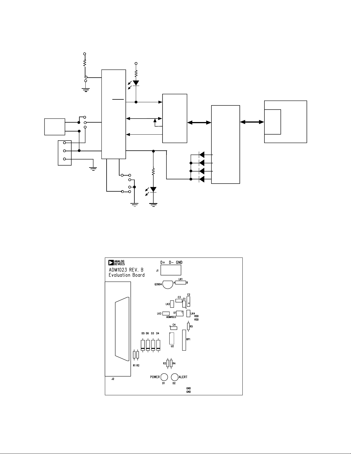
EVALUATION BOARD HARDWARE
The ADM1023 evaluation board contains the following
main components which can be identified from the block
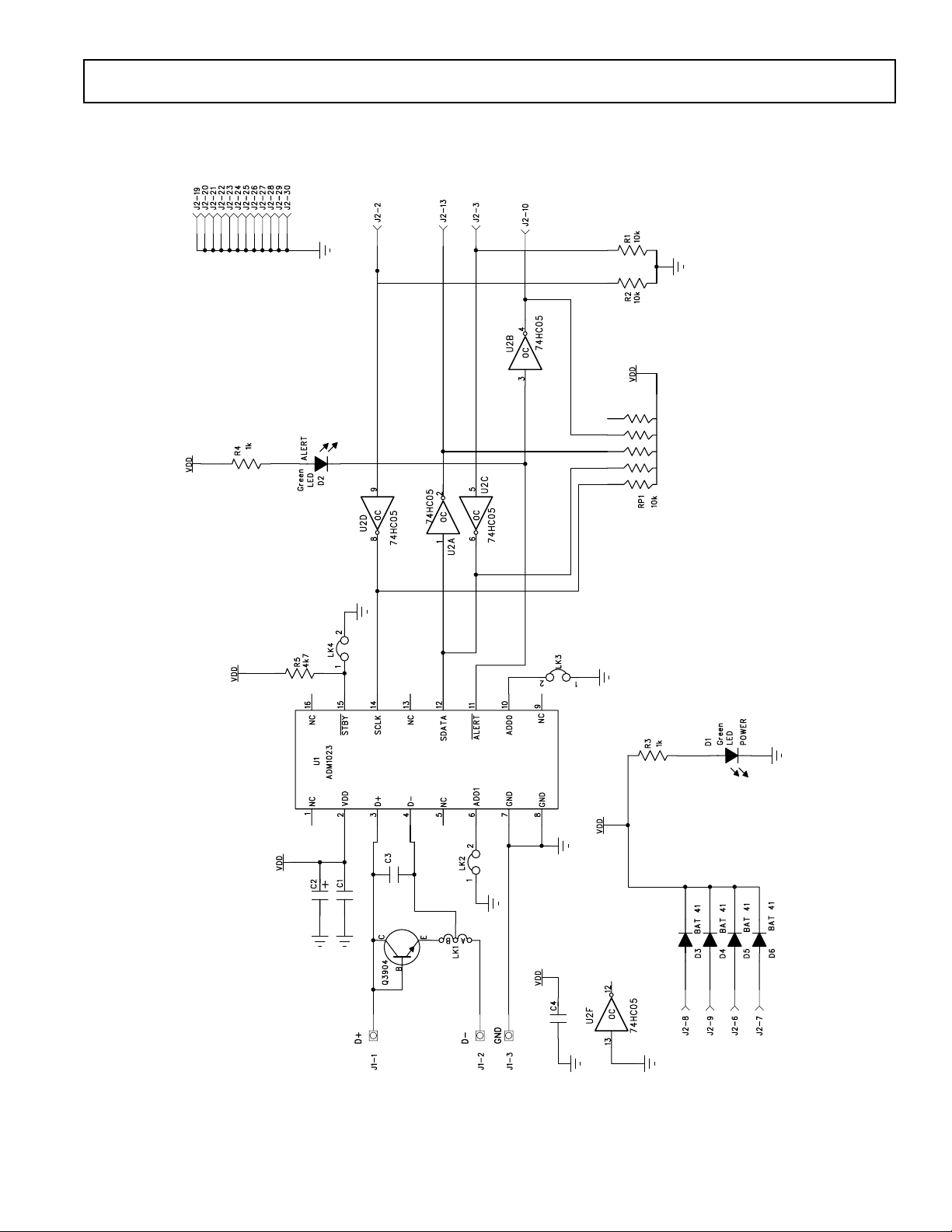
diagram, printed circuit board silk screen and schematic
diagram of figures 1, 2 and 3 overleaf.
ADM1023 IC
NPN sensor transistor
LED indicators for power and Alert
Jumpers for selecting sensor and for setting SMBus
address
Interface buffers
Connector for parallel interface
Test connector for connecting to CPU Transistor
REV. A 11/10/99
Information furnished by Analog Devices is believed to be accurate and
reliable. However, no responsibility is assumed by Analog Devices for its
use, nor for any infringements of patents or other rights of third parties
which may result from its use. No license is granted by implication or
otherwise under any patent or patent rights of Analog Devices.
Windows is a registered trademark of Microsoft Corporation
One T ec hnology Wa y, P.O. Box 9106, Norwood, MA 02062-9106, U.S.A.
Tel: 781/329-4700 Wor ld Wide Web Site: http://www .analog.com
Fax: 781/326-8703 Analog Devices, Inc., 1998
EVAL-ADM1023
Preliminary T echnical Data
V
DD
R5
4K7
V
DD
NPN
SENSOR
EXTERNAL
SENSOR
D+
D-
GND
TEST
CONNECTOR
J1
LK4
B
LK1
A
STBY
ALER T
ADM10 23
SDATA
D+
SCLK
DADD1
ADD0
LK2
V
DD
LK3
D2
RED
ALER T
BUFF E R S
D1
GREEN
POWER
36-WAY
CENTRONICS
CONNECTOR
(J2)*
PRELIMINARY
EL
LL
RA
PA
T
R
PO
PC
TECHNICAL
Figure 1. ADM1023 Evaluation Board Block Diagram
DATA
Figure 2. ADM1023 Evaluation Board SilkScreen
–2– REV. A
Preliminary T echnical Data
EVAL-ADM1023
PRELIMINARY
TECHNICAL
DATA
Figure 3. ADM1023 Evaluation Board Schematic
–3–REV. A

EVAL-ADM1023
Preliminary T echnical Data
CONNECTORS, SWITCHES AND INDICATORS
The function of the various connectors, links and
indicators on the evaluation board are explained below.
TEST CONNECTOR
Test Connector J1 allows an external diode to be
connected between the D+ and D- terminals of the
ADM1023
CENTRONICS INTERFACE CABLE
The evaluation board and the personal computer may be
connected via the printer parallel port using the contronics
cable provided. The connections to J2 are as follows.
REMOTE SENSOR SELECT LK1
The function of this jumper is to allow the user to choose
between measuring tempertature using the on-board
remote sensor and an external one connected between the
D+ and D- terminals of J1. When the middle pin is linked
to B the on-board sensor is used and when the middle pin
is linked to A the off-board sensor is used.
TABLE 1. ADM1023 SENSOR SELECTION
TABLE 2. ADM1023 DEVICE ADDRESSES
Address Pins Device Address
ADD1 (LK2) ADD0 (LK3) Binary Hex
0(LK2 Closed) 0(LK3 Closed) 0011000(0) 0
0(LK Closed) NC(LK Open) 0011001(0) 32
NC(LK2 Open) 0(LK3 Closed) 0101001(0) 52
NC(LK2 Open) NC(LK3 Open) 0101010(0) 54
STANDBY INPUT LK4
The ADM1023 has an active low standby input, pin 15
controlled by LK4 on the evaluation board. This is a logic
input that enables selection between normal operation
(high) and standby operation (low). Without the shorting
link the pin is high (normal mode). With the shorting link
the pin is low (standby mode). This input performs the
same function as bit 7 of the status register
LK1 Position Sensor Selected
A External Sensor
B On-baord NPN Sensor
SERIAL BUS ADDRESS SELECT
LK2 and LK3 are used to set the two LSB’s of the
ADM1023’s serial bus address, ADD0 and ADD1. These
pins are tri-state and can be grounded, left unconnected or
tied to V
possible. However for simplicity on the evaluation board a
jumper is used to allow each pin two states ( 4 Addresses).
The pin is floating when the shorting link is not on the
board. The pin is grounded when the shorting link is
placed on the board. It should be noted that ADD0 and
ADD1 are only read at power up. If LK2 or LK3 are
changed while the ADM1023 is on, the change of address
will not be effective until the device has been powered off
and then on again.
As the serial bus address is seven bits, when storing it as
an 8-bit word it must be left or right justified, with either
the MSB or the LSB of the 8-bit word as zero. The
ADM1023 evaluation software stores the 7-bit serial bus
address as left justified and makes the LSB zero. Table 2
shows the four possible addresses possible on the
evaluation board
. This means a total of nine addresses are
DD
PRELIMINARY
TECHNICAL
DATA
–4– REV. A

Preliminary T echnical Data
THE SOFTWARE
The software allows the ADM1023’s functions to be
controlled from the PC via an easy to use interface
operating under the Windows environment. The
contents of the devices internal registers can easily be read
or altered through a user-friendly graphics interface, while
the Control Centre window allows the graphing of the
temperature readings.
INSTALLING THE SOFTWARE
To install the software, insert the first disk of the program
software into drive A, click on the Start icon, click on
Run, then type A:setup.exe as the file name. If the 3.5inch
floppy disk drive is not drive “A” then type “X” instead of
“A” where “X” is the drive letter of the 3.5-inch floppy
disk drive.
USING THE SOFTWARE
When using the software, first ensure the evaluation board
is connected to the Parallel Printer Port.
To start the software, select Start-Programs-Analog
Devices-ADM1023 Eval Software.
When the program is started, a startup screen will appear.
Press any key or mouse button to go onto the next step,
which is the Software Initialisation Wizard.
PRELIMINARY
Fig 4. Evaluation Software Startup Screen
EVAL-ADM1023
TECHNICAL
DATA
–5–REV. A

EVAL-ADM1023
Click on “Next” to go to the next screen, which allows
the user to select between connecting the evaluation board
via the printer port or via the SMBus. The PIIX4 SMBus
Interface is intended for when the ADM1023 is present on
the PC’s motherboard. While using the evaluation board
the Parallel Printer Port Option should always be selected.
Preliminary T echnical Data
The software will search for the ADM1023 and when it is
found the following screen will appear. The device address
given will depend on the settings of J7 and J8
If this is the device the user intends to use, click on “Yes”
and the following screen appears. If the user wants to use a
different device click on “No” to continue searching.
PRELIMINARY
TECHNICAL
Once the communication medium has been selected, click
on “Next” to go to the next screen. When you are ready
for the software to begin searching for the evaluation
board on either the parallel port or the SMBus , click
“Next”
DATA
If the device was not found the following screen will
appear. In this case check the connections to the
evaluation board, click on “Back” and try again. If this
does not work then try re-booting the PC and re-running
the software
–6– REV. A

Preliminary T echnical Data
EVAL-ADM1023
When the software has successfully found the ADM1023,
click on “Finish”. An index-card type display with three
tabs will be displayed on the screen.
The Main Tab shows the software version and allows the
user to run the communications setup or quit the program.
It is also possible to quit the program by clicking on
READ/WRITE
This tab displays information about the ADM1023's internal
registers and allows their contents of be read and/or altered.
Each register has a button associated with it. Clicking on a
button will display the contents of the selected register in the
register contents box and the name of each register bit. The
register contents are also displayed in hexadecimal and decimal.
Clicking on a register button causes its contents to be read once
if continuous reading is off. If continuous reading is on, the
register continuous will be updated continuously. Click the
button to toggle between
.
The type of register selected, its hexadecimal address, its current
value in hexadecimal and decimal and the previous value written
to the register, are also displayed.
and
Data may be written to all registers that are Read/Write ,(refer to
data sheet for more information). When the Read/Write tab is
first selected, none of the registers have been written to, and
they contain their default values.
Registers may be written to in two ways. Clicking on a bit in the
Read/Write display will toggle its value between 0 and 1. This is
useful where a function is controlled by setting or clearing
individual bits in a register, for example, turning standby mode
on or off by setting or clearing the Op. Mode bit in the
Configuration Register.
The entire contents of a register may be changed by typing a
Hex or decimal value in the text boxes of the Write display. The
button will change from green to red and the new value can be
written to the register by clicking on the button.
This is useful where a register contains a numeric value such as
a temperature limit.
The ADM1023 may be put into standby mode by clicking on the
PRELIMINARY
button, or by setting bit 6 of the
Configuration Register. The legend on the button will change to
and clicking it again will return the
ADM1023 to normal operating mode.
TECHNICAL
Figure 5. Main Program Tab
DATA
–7–REV. A

EVAL-ADM1023
Preliminary T echnical Data
ONE-SHOT OPERATION
When the ADM1023 is put into standby mode by setting bit 6 of
the Configuration register or clicking on the
button, a one-shot reading of the
remote temperature may be taken by clicking on the
button. The temperature found
will then be displayed.
CONTROL CENTER
The Control Center tab allows readings to be displayed
graphically on bargraphs or line graphs.
BAR GRAPHS
At the bottom of the Control Center tab are bargraphs for the
local and remote sensors. These can be toggled on and off by
clicking on the button. The legend will
change to and clicking again will turn off
the bargraphs. The high and low temperature limits can be
changed by moving the pointer arrows below the bargraphs.
The ADC sampling rate can be changed by rotating the control
knob next to the bargraphs.
PRELIMINARY
Figure 6. Read/Write Program Tab
TECHNICAL
ALERT INDICATION
When the Control Center tab is first selected, the Alert Status
Indicator is off.
If Alert detection is turned on by clicking on the
button. The legend will change to
and the indicator
will become active. It will change from green to red
when the local or remote temperature
goes outside limits, and the ALERT LED (D2) on the evaluation
board will light. The LED can be turned off by clicking on the
button, provided the temperature has
gone back within limits, or the limits have been adjusted to be
outside the temperature reading. The Alert Status Indicator
automatically changes back to green when the temperature is
within limits. Alert detection can be turned off again by clicking
on
.
DATA
–8– REV. A

Preliminary T echnical Data
LINE GRAPHS
Line graphs of temperature against time can be plotted by
EVAL-ADM1023
clicking on the
change to and clicking again will stop the
graph.
While the graph is displayed on the screen, it is possible to zoom
in or out by moving the arrows on the temperature and time
axes. Moving the lower arrow up the temperature axis increases
the minimum temperature shown on the axis, while moving the
upper arrow down decreases the maximum temperature displayed, thus zooming in on a narrower temperature range.
Similarly, moving the left arrow to the right on the time axis and/
or the right arrow to the left displays a narrower band of time on
this axis.
The graph can be cleared by clicking on the
button.
button. The legend will
Figure 7. Control Centre Program Tab
PRELIMINARY
TECHNICAL
DATA
–9–REV. A

EVAL-ADM1023
Preliminary T echnical Data
Figure 8. Normal Graph
PRELIMINARY
TECHNICAL
Figure 9. Zoomed In
EASY SETUP
The line and bargraphs can be started with a single click
by clicking on the
the line and bargraphs, sets temperature limits of 0°C and
90´°C and turns on the Alert detection.
button . This starts
DATA
LOG TO FILE
This function allows the user to record the values of the remote
and local temperatures to a Microsoft Excel file. The frequency
at which values are stored to the file are determined by the
delay(sec) window. To change this value, click on the screen
and type in the new value in seconds.
–10– REV. A

Preliminary T echnical Data
EVAL-ADM1023
Figure 9. Opening a New Log to File
PRELIMINARY
To start a new Log click on the "Make New Log" button . The
above "Open" Box will appear. Type in a name for the file and
click "Open". The program will begin storing the values of both
the remote and local temperatures to the file at the chosen
intervils.The number of lines logged will be displayed on the
Control Centre Window. To stop writing to the file click on the
"Not Logging to file" button.
To view this table open the document using Microsoft Excel.
TECHNICAL
ABOUT MENU
The About Menu on the main menu tab gives information about
DATA
the software and contains the copyright notice
Figure 10. About Menu
–11–REV. A

EVAL-ADM1023
APPENDIX B. COMPONENT LIST
Capacitors
C1,C4 0.1µ F
C2 10µF tantalum
C3 Not fitted
Resistors
R1, R2 10k
R3,R4 1k
R5 4.7k
RP1 10k x 5-way SIL resistor pack
Semiconductors
Q3904 2N3904
D1 Green LED
D2 Red LED
D5 - D8 BAT41
Connectors
J1 2mm x 3-way test socket
Preliminary T echnical Data
J2 36-way Centronics connector
LK1 3-pin Jumper
LK2, LK3, LK4 2-pin Jumper
Misc
PRELIMINARY
TECHNICAL
U1 ADM1023
U2 74AC05M Buffers
DATA
–12– REV. A
 Loading...