

Page 1
Engineer-to-Engineer Note EE-241
a
Technical notes on using Analog Devices DSPs, processors and development tools
Contact our technical support at dsp.support@analog.com and at dsptools.support@analog.com
Or vi sit our o n-li ne r esou rces htt p:/ /www.analog.com/ee-notes and http://www.analog.com/processors
SHARC® DSPs to TigerSHARC® Processors Code Porting Guide
Contributed by Andrew Caldwell and Maikel Kokaly-Bannourah Rev 1 – July 14, 2004
1 Introduction
The following Engineer-to-Engineer note discusses the differences between Analog Devices Inc. (ADI)
first and second generation ADSP-2106x and ADSP-2116x SHARC® DSPs and ADSP-TS101 and
ADSP-TS20x TigerSHARC® processors.
Over the years, the SHARC DSP architecture has become the world leader for high-end multiprocessor
applications. The introduction of the ultra-high performance TigerSHARC architecture makes it the ideal
upgrade device for existing SHARC systems looking for a performance boost and a system cost reduction.
This document is a step-by-step, how-to guide for porting SHARC code to its TigerSHARC equivalent.
Architectural differences are discussed, and multiple code examples are provided to help you upgrade
existing SHARC source code to the next generation of floating-point processors, the TigerSHARC
processor family.
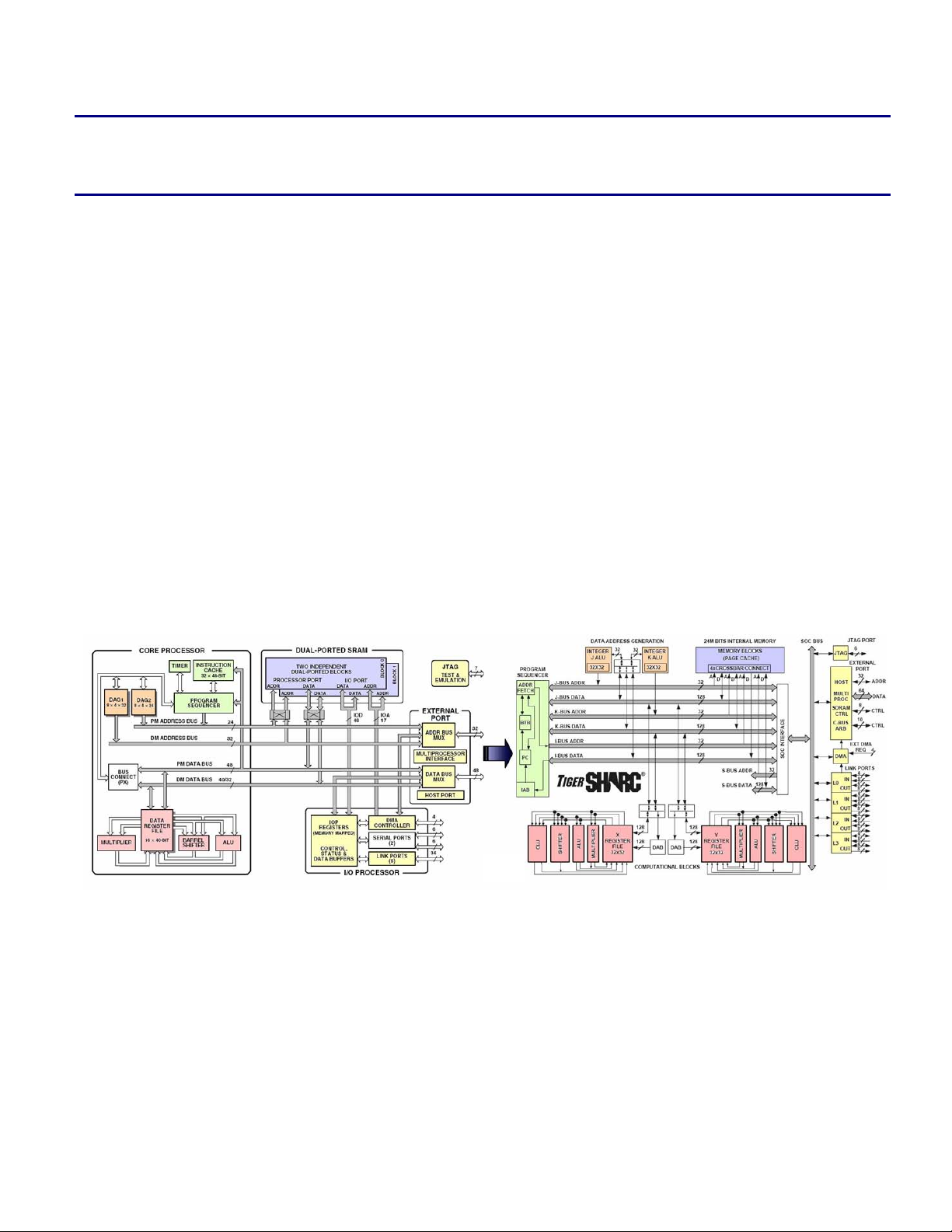
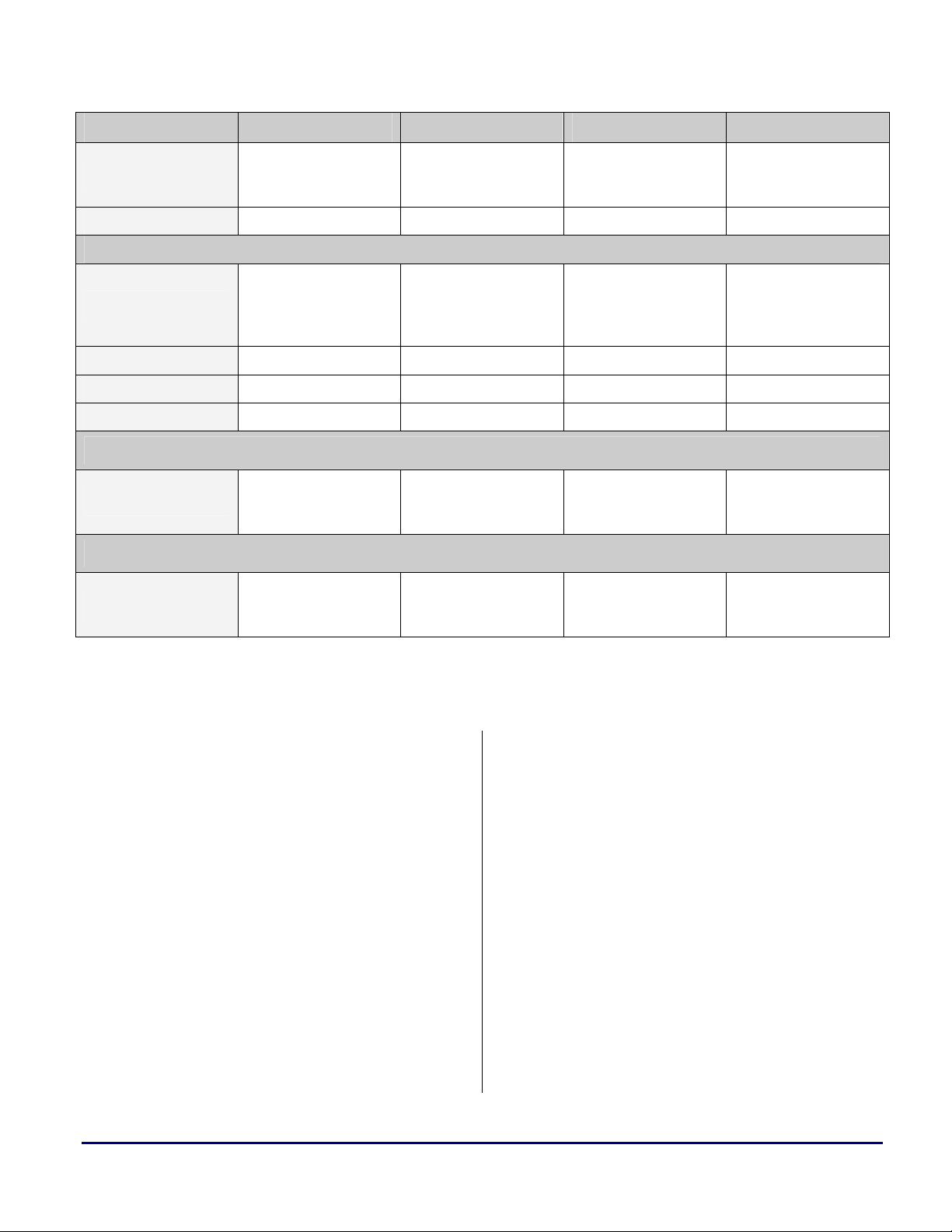
Figure 1. SHARC DSP and TigerSHARC Processor Block Diagrams
Copyright 2004, Analog Devices, Inc. All rights reserved. Analog Devices assumes no responsibility for customer product design or the use or application of
customers’ products or for any infringements of patents or rights of others which may result from Analog Devices assistance. All trademarks and logos are property
of their respective holders. Information furnished by Analog Devices applications and development tools engineers is believed to be accurate and reliable, however
no responsibility is assumed by Analog Devices regarding technical accuracy and topicality of the content provided in Analog Devices’ Engineer-to-Engineer Notes.
Page 2

a
2 Table of Contents
1 Introduction .......................................................................................................................................................................................................1
2 Table of Contents ..............................................................................................................................................................................................2
2.1 Code Listing..............................................................................................................................................................................................3
2.2 Table Listing .............................................................................................................................................................................................4
3 Architecture Overview ......................................................................................................................................................................................5
4 SHARC-to-TigerSHARC Conversion Guidelines.............................................................................................................................................7
4.1 Register File..............................................................................................................................................................................................9
4.2 Data Addressing......................................................................................................................................................................................10
4.2.1 Circular Buffers...............................................................................................................................................................................11
4.2.2 Addressing in SISD and SIMD.......................................................................................................................................................11
4.3 Program Sequencer .................................................................................................................................................................................12
4.3.1 Instruction Pipeline .........................................................................................................................................................................12
4.3.2 Instruction Cache and BTB............................................................................................................................................................. 12
4.3.3 Program Flow Variations................................................................................................................................................................13
4.3.4 Interrupts......................................................................................................................................................................................... 14
4.4 DMA .......................................................................................................................................................................................................21
5 SHARC-to-TigerSHARC Conversion Examples.............................................................................................................................................22
5.1 Register File............................................................................................................................................................................................22
5.2 Data Addressing......................................................................................................................................................................................22
5.2.1 Post-Modify and Pre-Modify ..........................................................................................................................................................22
5.2.2 Circular Buffers...............................................................................................................................................................................23
5.2.3 Addressing in SISD and SIMD.......................................................................................................................................................23
5.3 Program Sequencer .................................................................................................................................................................................24
5.3.1 Pipeline............................................................................................................................................................................................24
5.3.2 Loops...............................................................................................................................................................................................24
5.3.3 Interrupts......................................................................................................................................................................................... 25
5.4 DMAs...................................................................................................................................................................................................... 31
5.4.1 Internal Memory - External Memory..............................................................................................................................................31
5.4.2 Internal Memory - Internal Memory of other DSPs (Multiprocessing)........................................................................................... 33
5.4.3 Internal Memory - Link Port I/O.....................................................................................................................................................34
6 C Run-Time Environment ...............................................................................................................................................................................36
6.1 Memory .SECTION and SECTION{} Names........................................................................................................................................36
6.2 Register Classification.............................................................................................................................................................................38
6.2.1 Callee Preserved Registers (“Preserved”) .......................................................................................................................................38
6.2.2 Caller Save Registers (“Scratch”) ...................................................................................................................................................38
6.3 Stack Frame Overview and Differences.................................................................................................................................................. 38
6.3.1 Stack Pointer and Frame Pointer.....................................................................................................................................................38
6.3.2 Run-Time Stack ..............................................................................................................................................................................39
6.4 Code Conversion from SHARC DSPs to TigerSHARC Processors........................................................................................................ 39
6.4.1 Procedure Call.................................................................................................................................................................................39
6.4.2 Function Prologue...........................................................................................................................................................................41
6.4.3 Pushing Additional Data to the Stack..............................................................................................................................................42
6.4.4 Argument Passage...........................................................................................................................................................................44
6.4.5 Popping Data from the Stack...........................................................................................................................................................46
6.4.6 Return Values..................................................................................................................................................................................48
6.4.7 Function Epilogue...........................................................................................................................................................................48
6.4.8 Using Mixed C/C++ and Assembly Naming Conventions.............................................................................................................. 49
6.5 Heaps.......................................................................................................................................................................................................50
6.6 Summary................................................................................................................................................................................................. 54
7 Algorithm Code Examples ..............................................................................................................................................................................55
7.1 DFT......................................................................................................................................................................................................... 55
7.1.1 MEMORY Sections ........................................................................................................................................................................56
7.1.2 Reset Interrupt Vector..................................................................................................................................................................... 57
7.1.3 Call DB ...........................................................................................................................................................................................57
SHARC® DSPs to TigerSHARC® Processors Code Porting Guide (EE-241) Page 2 of 64
Page 3

7.1.4 Data Addressing..............................................................................................................................................................................57
7.2 FIR ..........................................................................................................................................................................................................57
7.2.1 FIR One-to-One Conversion ...........................................................................................................................................................57
7.2.2 Optimized FIR.................................................................................................................................................................................61
8 Conclusion .......................................................................................................................................................................................................63
9 References .......................................................................................................................................................................................................64
10 Document History..........................................................................................................................................................................................64
a
2.1 Code Listing
Code 1. JALU and KALU Parallel Instructions .................................................................................................................................................11
Code 2. Predicted and Non-predicted Branch.....................................................................................................................................................13
Code 3. SHARC DSP Loop................................................................................................................................................................................ 14
Code 4. TigerSHARC Processor Loop............................................................................................................................................................... 14
Code 5. SHARC vs. TigerSHARC Register File Sets........................................................................................................................................ 22
Code 6. Post-modify and Pre-modify Data Addressing Operations ...................................................................................................................23
Code 7. Circular Buffers.....................................................................................................................................................................................23
Code 8. SISD, SIMD and Broadcast Loads........................................................................................................................................................ 23
Code 9. Delayed Branch.....................................................................................................................................................................................24
Code 10. Single Loop......................................................................................................................................................................................... 25
Code 11. Nested Loops.......................................................................................................................................................................................25
Code 12. Standard Timer Interrupt.....................................................................................................................................................................27
Code 13. Nested IRQ Interrupt...........................................................................................................................................................................28
Code 14. Re-usable IRQ Interrupt...................................................................................................................................................................... 29
Code 15. User Software Exception.....................................................................................................................................................................31
Code 16. SHARC and TigerSHARC to External Memory Device DMA Example...........................................................................................32
Code 17. SHARC and TigerSHARC Multiprocessor DMA Example................................................................................................................ 34
Code 18. SHARC and TigerSHARC Multiprocessor DMA Example................................................................................................................ 35
Code 19. ADSP-2106x/2116x Procedure Call....................................................................................................................................................40
Code 20. ADSP-21020 Procedure Call...............................................................................................................................................................40
Code 21. TigerSHARC Procedure Call..............................................................................................................................................................40
Code 22. SHARC Function Call Macro .............................................................................................................................................................41
Code 23. TigerSHARC Function Call Macro..................................................................................................................................................... 41
Code 24. TigerSHARC Function Prologue Macros............................................................................................................................................41
Code 25. Post-Modify Store to the J Stack.........................................................................................................................................................42
Code 26. SHARC “puts” Macro.........................................................................................................................................................................42
Code 27. TigerSHARC "puts" Macros............................................................................................................................................................... 42
Code 28. Example Showing "puts" Macro Usage ..............................................................................................................................................43
Code 29. SHARC and TigerSHARC "save_reg" Macros................................................................................................................................... 44
Code 30. SHARC "reads(x)" Macro...................................................................................................................................................................44
Code 31. TigerSHARC "reads(x)" Macro ..........................................................................................................................................................45
Code 32. C Source for Function Block FIR Function Call.................................................................................................................................45
Code 33. Example for Retrieval or Arguments Passed to Block FIR.................................................................................................................46
Code 34. SHARC "gets(x)" Macro.....................................................................................................................................................................46
Code 35. TigerSHARC "gets(x)" Macro ............................................................................................................................................................46
Code 36. SHARC "alter(x)" Macro....................................................................................................................................................................46
Code 37. TigerSHARC "alter(x)" Macro............................................................................................................................................................46
Code 38. "restore_reg" Macro on SHARC DSPs...............................................................................................................................................47
Code 39. "restore_reg" Macro on TigerSHARC Processors...............................................................................................................................47
SHARC® DSPs to TigerSHARC® Processors Code Porting Guide (EE-241) Page 3 of 64
Page 4

Code 40. Pushing and Popping the Stack Example............................................................................................................................................48
Code 41. ADSP-21020 and ADSP-21160 Function Epilogue Macros............................................................................................................... 48
Code 42. SHARC Function Epilogue Macros....................................................................................................................................................49
Code 43. TigerSHARC Function Epilogue Macros............................................................................................................................................49
Code 44. SHARC Heap Declaration in "seg_init.asm" ......................................................................................................................................51
Code 45. SHARC Heap MEMORY Section Placement within the .LDF...........................................................................................................51
Code 46. TigerSHARC Heap Declaration in "ts_hdr.asm".................................................................................................................................51
Code 47. TigerSHARC Heap Memory Section Placement within the .LDF......................................................................................................51
Code 48. SHARC Multiple Heap Declaration in "seg_init.asm"........................................................................................................................52
Code 49. SHARC Multiple Heap Memory Section Placement within the .LDF................................................................................................53
Code 50. TigerSHARC Multiple Heap Declaration in "ts_hdr.asm".................................................................. ................................................ 53
Code 51. TigerSHARC Processors Multiple Heap Memory Section Placement within LDF ............................................................................53
Code 52. SHARC and TigerSHARC DFT Example ..........................................................................................................................................56
Code 53. Floating Point Block FIR One-to-One Conversion .............................................................................................................................60
Code 54. Optimized Floating Point Block FIR...................................................................................................................................................62
a
2.2 Table Listing
Table 1. SHARC and TigerSHARC Features Overview................................................................................ ...................................................... 6
Table 2. SHARC DSP and TigerSHARC Processor Registers Mapping Scheme ................................................................................................9
Table 3. Sequencer Instructions..........................................................................................................................................................................20
Table 4. Condition and Loop Termination Codes...............................................................................................................................................21
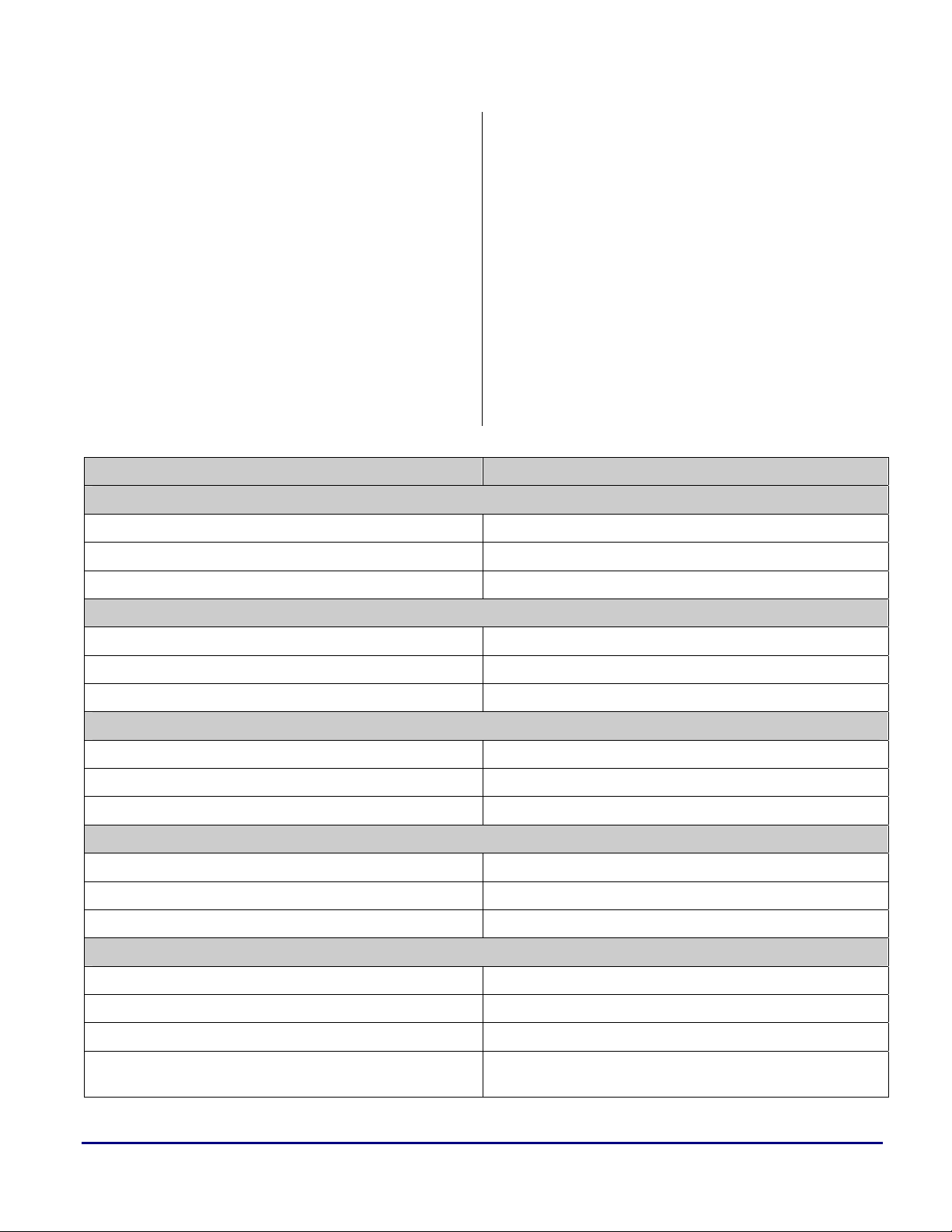
Table 5. SHARC and TigerSHARC Default Memory Sections .........................................................................................................................37
Table 6. Frame & Stack Pointer Registers..........................................................................................................................................................38
Table 7. Registers used for Passing Arguments..................................................................................................................................................44
Table 8. Parameter Return Registers ..................................................................................................................................................................48
Table 9. Accessing C from Assembly ................................................................................................................................................................49
Table 10. Accessing Assembly from C...............................................................................................................................................................49
Table 11. Accessing C++ from Assembly..........................................................................................................................................................50
Table 12. Accessing Assembly from C++..........................................................................................................................................................50
Table 13. SHARC and TigerSHARC Heap Management Functions..................................................................................................................54
SHARC® DSPs to TigerSHARC® Processors Code Porting Guide (EE-241) Page 4 of 64
Page 5

a
3 Architecture Overview
The first and second generation SHARC - Super
Harvard Architecture Computer – DSPs, ADSP-
2106x and ADSP-2116x, build on the ADSP21000 DSP core family to form a complete
system-on-chip, adding dual-ported on-chip
SRAM, and integrated I/O peripherals.
The SHARC architecture combines a highperformance floating-point DSP core with
integrated on-chip features including a host
processor interface, DMA controller, serial ports,
link ports, and shared bus connectivity for
glueless multiprocessing for up to six SHARC
processors.
This architecture balances a high-performance
DSP core with high-performance buses, yielding
an ideal solution for audio, military,
communications, test equipment, motor control,
imaging and many other applications.
The ADSP-TSxxx TigerSHARC processor
family sets a new standard of performance for
digital signal processors, combining multiple
computation units for floating-point and fixedpoint processing, as well as very large word
widths.
This new architecture maintains a system-on-achip, scalable computing design philosophy,
including up to 24 Mbits of on-chip memory,
integrated I/O peripherals, a host processor
interface, DMA controllers, link ports, and
shared bus connectivity for glueless
multiprocessing of up to eight TigerSHARC
processors.
The TigerSHARC processor’s extremely highperformance core and increased feature set
makes it the ideal upgrade device for existing
SHARC systems looking for a performance
boost and a system cost reduction.
Due to the architectural changes (added units,
modified pipeline, increased memory structure,
internal bus architecture improvement, etc.)
introduced when moving from SHARC DSPs to
TigerSHARC processors, the source code
requires modification to overcome code
incompatibility.
This document first examines the main
differences between the two architectures and
then shows you how to convert SHARC source
code to its TigerSHARC equivalent.
Table 1 summarizes these two architectures main
features.
SHARC® DSPs to TigerSHARC® Processors Code Porting Guide (EE-241) Page 5 of 64
Page 6
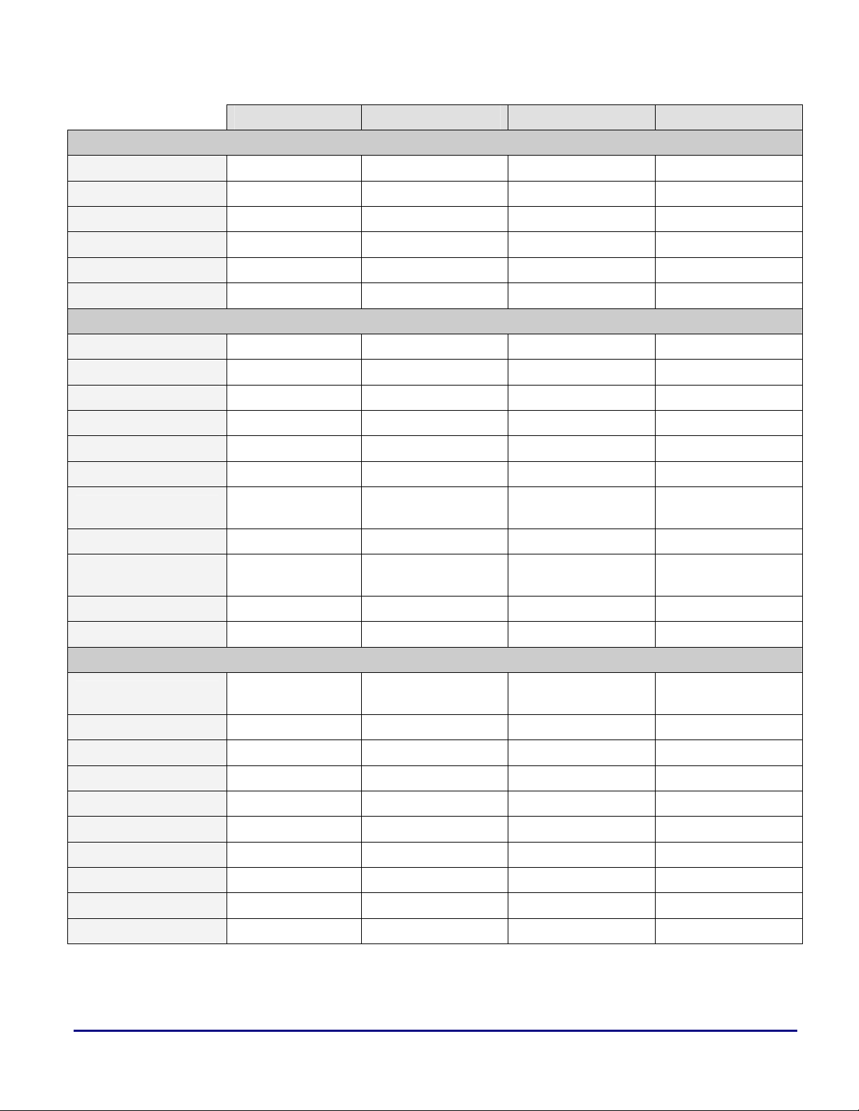
Production Process 0.35-0.5 microns 0.18-0.25 microns 0.13 microns 0.13 microns
Core Clock Rate 40-66 MHz 80-100 MHz 250-300 MHz 500-600 MHz
Temperature Range -40° to 85°C -40° to 85°C -40° to 85°C -40° to 85°C
Core Supply Voltage 5 V / 3.3 V 2.5 V / 1.9 V 1.2 V 1.0 V / 1.2 V
I/O Supply Voltage 5 V / 3.3 V 3.3 V 3.3 V 2.5 V
Package Size 23x23 mm 27x27 mm 19x19 / 27x27 mm 25x25 mm
Core SISD SIMD MIMD MIMD
Processing Elements X X and Y X and Y X and Y
Register File 32x40 bits 64x40 bits 64x32 bits 64x32 bits
Fixed-point data 32-bit 32-bit 8-, 16-, 32-, 64-bit 8-, 16-, 32-, 64-bit
Floating-point data 32-, 40-bit 32-, 40-bit 32-, 40-bit 32-, 40-bit
Pipeline Depth 3 stages 3 stages 8 stages 10 stages
ADSP-2106x ADSP-2116x ADSP-TS101 ADSP-TS20x
Electrical and Mechanical Features
Core Features
a
Branch Prediction N/A N/A
Memory 0.5-4 Mbit 1-4 Mbit 6 Mbit 4-24 Mbit
Internal Data Bus Width
Data Addressing DAGs DAGs IALUs IALUs
Timers 1 / 2 1 2 2
External Memories SRAM, SDRAM
External Bus Width 48 bits 32/64 bits 32/64 bits 32/64 bits
DMA Channels 10 14 14 14
I/O Throughput 300M bytes/sec 800M bytes/sec 1.8G bytes/sec 4G bytes/sec
Multiprocessor 6 + Host 6 + Host 8 + Host 8 + Host
Link Ports 6 x 4-bits 6 x 4/8 bits 4 x 8-bits 2-4 x 8-bits (LVDS)
Link Ports Compatibility ADSP-2116x ADSP-2106x N/C N/C
Serial Ports 2 2-4 N/A N/A
IRQ Lines 3 3 4 4
1x40-bit and 1x48-
bit
2x64–bit 3x128-bit 4x128-bit
External Interfaces
SRAM, SBSRAM,
SDRAM
Branch Target Buffer
(BTB)
SRAM, SBSRAM,
SDRAM
Branch Target Buffer
(BTB)
SRAM,SBSRAM,
SDRAM
G-P I/O Pins 4 4 4 4
N/A: Not Applicable, N/C: Not Compatible
Table 1. SHARC and TigerSHARC Features Overview
SHARC® DSPs to TigerSHARC® Processors Code Porting Guide (EE-241) Page 6 of 64
Page 7
a
4 SHARC-to-TigerSHARC
Conversion Guidelines
The SHARC-to-TigerSHARC register
map shown throughout this EE-Note is
not fixed. It is simply an example of
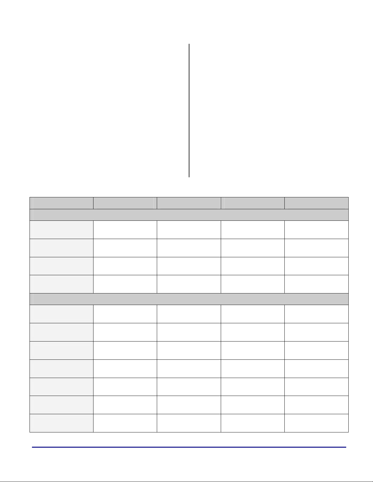
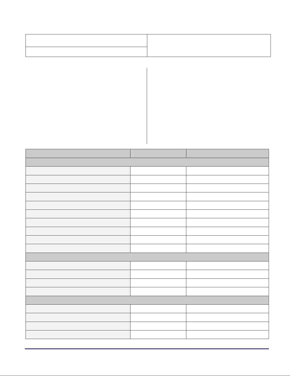
Table 2 shows the ADSP-2106x and ADSP-
how this can be done.
2116x SHARC DSPs registers, along with their
TigerSHARC processor (ADSP-TS101 and
ADSP-TS20x) equivalent.
The given mapping scheme has been
selected to provide code translation in
the simplest way, with the SHARC DSP
The main differences between the two
family features in mind.
architectures, and how they can be mapped to
each other, are discussed.
This does not necessarily mean that it
will produce the most efficient
TigerSHARC code. It will, however,
help you to translate source code to run
on TigerSHARC platforms.
Register Type ADSP-2106x ADSP-2116x ADSP-TS101 ADSP-TS201
Register File
Processing Element X
(P/R)
Processing Element X
(S/R)
Processing Element Y
(P/R)
Processing Element Y
(S/R)
Index (P/R)
Index (S/R)
Modify (P/R)
Modify (S/R)
Circular Buffers
Length
R15-0, F15-0 R15-0, F15-0 xR15:0, xFR15-0 xR15:0, xFR15-0
R’15-0, F’15-0 R’15-0, F’15-0 xR31:16,xFR31-16 xR31:16,xFR31-16
N/A S15:0, SF15-0 yR15-0, yFR15-0 yR15-0, yFR15-0
N/A S’15:0, SF15-0 yR31-16,yFR31-16 yR31-16,yFR16-0
Data Addressing
I7-0(DAG1),
I15-8(DAG2)
I’7-0(DAG1),
I’15-8(DAG2)
M7-0(DAG1),
M15-8(DAG2)
M’7-0(DAG1),
M’15-8(DAG2)
I7-0(DAG1),
I15-8(DAG2)
L7-0(DAG1),
L15-8(DAG2)
I7-0(DAG1),
I15-8(DAG2)
I’7-0(DAG1),
I’15-8(DAG2)
M7-0(DAG1),
M15-8(DAG2)
M’7-0(DAG1),
M’15-8(DAG2)
I7-0(DAG1),
I15-8(DAG2)
L7-0(DAG1),
L15-8(DAG2)
J11-4(JALU),
K11-4(KALU)
J27-20(JALU),
K27-20(KALU)
J19-12(JALU),
K19-12(KALU)
J30-28(JALU),
K30-28(KALU)
J3-0(JALU),
K3-0(KALU)
JL3-0(JALU),
KL3-0(KALU)
J11-4(JALU),
K11-4(KALU)
J27-20(JALU),
K27-20(KALU)
J19-12(JALU),
K19-12(KALU)
J30-28(JALU),
K30-28(KALU)
J3-0(JALU),
K3-0(KALU)
JL3-0(JALU),
KL3-0(KALU)
Base
SHARC® DSPs to TigerSHARC® Processors Code Porting Guide (EE-241) Page 7 of 64
B7-0(DAG1),
B15-8(DAG2)
B7-0(DAG1),
B15-8(DAG2)
JB3-0(JALU),
KB3-0(KALU)
JB3-0(JALU),
KB3-0(KALU)
Page 8
a
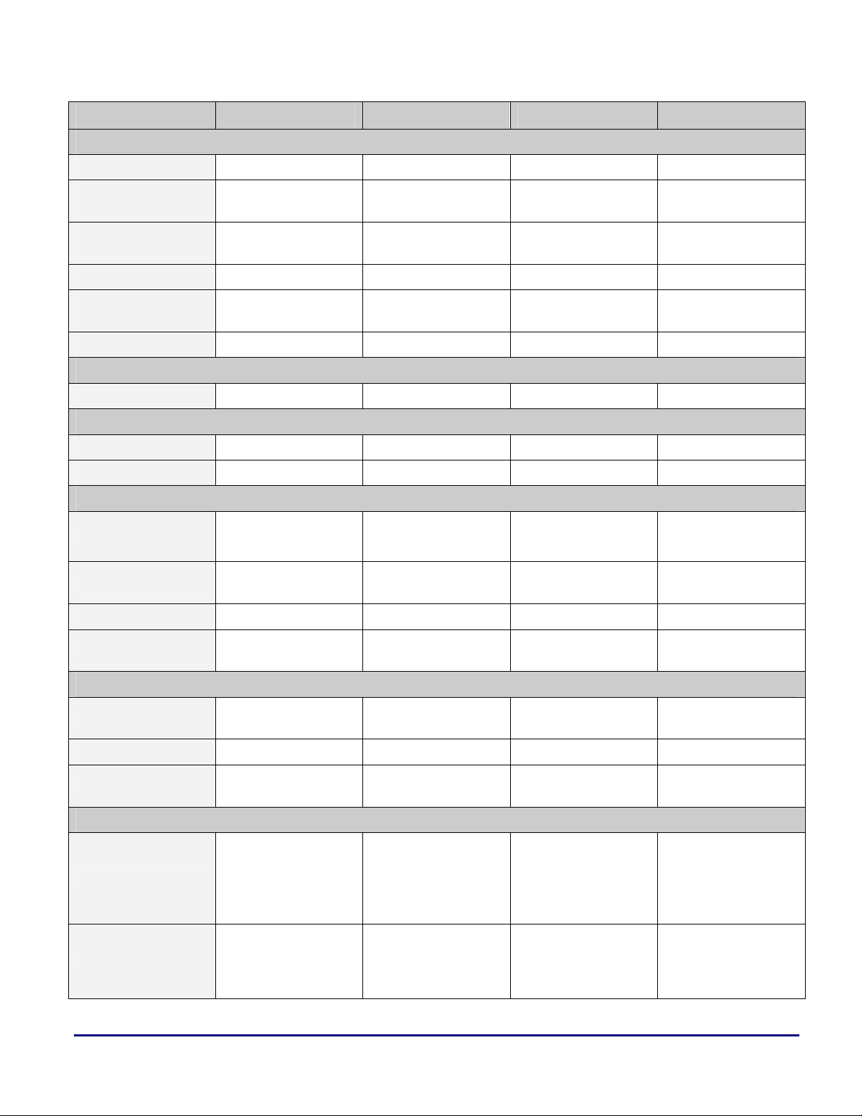
Register Type ADSP-2106x ADSP-2116x ADSP-TS101 ADSP-TS201
Program Sequencer
Program Counter PC PC PC PC
Program Counter
Stack
Program Counter
Stack Pointer
Loop Counter LCNTR LCNTR LC1-0 LC1-0
Loop Termination
Address
Current Loop Counter CURLCNTR CURLCNTR N/A N/A
PX, PX1 & PX2 PX, PX1 & PX2 N/A N/A
Period Register TPERIOD TPERIOD TMRIN1-0H/L TMRIN1-0H/L
Count Register TCOUNT TCOUNT TIMER1-0H/L TIMER1-0H/L
Control MODE2-1 MODE2-1 SQCTL
Interrupts
PCSTK PCSTK N/A N/A
PCSTKP PCSTKP N/A N/A
LADDR LADDR N/A N/A
Bus Exchange
Timer
System Registers
SQCTL,
INTCTL
IRPTL, IMASK,
IMASKP
IRPTL, IMASK,
IMASKP, MMASK
ILATH/L, IMASH/L,
PMASKH/L
ILATH/L, IMASH/L,
PMASKH/L
Flags MODE2 FLAGS SQCTL FLAGS
Status
Configuration
IOP Registers MSGR7-0 MSGR7-0 N/A N/A
Bus
External Port
Link Port
ASTAT, STKY,
USTAT2-1
SYSCON, SYSTAT,
WAIT, VIRPT
MODE2, BMAX,
BCNT
EPB3-0, DMAC9-6,
II9-6, EI9-6, IM9-6,
EM9-6, C9-6, EC9-6,
CP9-6, GP9-6
II5-3, II1, IM5-3, IM1,
C5-3, C1, CP5-3, CP1,
GP5-3, GP1, DB5-3,
DB1, DA5-3, DA1
ASTATx/y, STKYx/y,
USTAT4-1
System Control
SYSCON, SYSTAT,
WAIT, VIRPT
MODE2, BMAX,
BCNT
DMA
EPB3-0, DMAC13-10,
II13-10, EI13-10,
IM13-10, EM13-10,
C13-10, EC13-10,
CP13-10, GP13-10
II9-4, IM9-4, C9-4,
CP9-4, GP9-4, DB9-4,
DA9-4
ASTATx/y,
JSTATx/y, KSTATx/y
SYSCON, SYSTAT,
SDRCON
BUSLK, BMAX,
BMAXC
DCS3-0, DCD3-0,
DC13-12, DCNT
DC11-4, DCNT DC11-4, DCNT
ASTATx/y,
JSTATx/y, KSTATx/y
SYSCON, SYSTAT,
SDRCON
BUSLK, BMAX,
BMAXC
DCS3-0, DCD3-0,
DC13-12, DCNT
SHARC® DSPs to TigerSHARC® Processors Code Porting Guide (EE-241) Page 8 of 64
Page 9
Register Type ADSP-2106x ADSP-2116x ADSP-TS101 ADSP-TS201
a
II3-0, IM3-0, C3-0,
Serial Port
Status DMASTAT DMASTAT DSTAT DSTAT
Buffer & Control LBUF5-0, LCTL
Common LCOM LCOM LSTAT3-0 LSTAT3-0
Assignment LAR LAR N/A N/A
Service Request LSRQ LSRQ LSTAT3-0 LSTAT3-0
Buffer & Control
P/R: Primary Registers, S/R: Secondary Registers, N/A: Not Applicable
CP3-0, GP3-0, DB3-0,
DA3-0
TX1-0, RX1-0,
STCTL1-0,
SRCTL1-0
MR, MR2-0, MRF,
MRF2-0, MRB,
MRB2-0
II3-0, IM3-0, C3-0,
CP3-0, GP3-0, DB3-0,
DA3-0
Link Port Control
LBUF5-0, LCTL1-0,
LIRPTL
Serial Port Control
TX1-0, RX1-0,
STCTL1-0,
SRCTL1-0
Multiplier Registers
MR, MR2-0, MRF,
MRF2-0, MRB,
MRB2-0
N/A N/A
LCTL3-0,
LBUFTX3-0,
LBUFRX3-0
N/A N/A
MR3-0, MR4 MR3-0, MR4
LRCTL3-0,
LTCTL3-0,
LBUFTX3-0,
LBUFRX3-0
Table 2. SHARC DSP and TigerSHARC Processor Registers Mapping Scheme
4.1 Register File
The register file of first-generation ADSP-2106x
processors features two sets (primary and
secondary) of 16 40-bit-wide registers (R0-R15)
for fast context switching.
The same applies to the ADSP-2116x SHARC
DSP register file, with the addition of a second
register file set (
(Single-Instruction Multiple-Data). The two
register files and the included arithmetic units are
referred to as Processing Element X (PEx) and
Table 2 lists TigerSHARC processor
registers that are relevant to the SHARC
DSPs registers. It does not list all
TigerSHARC registers.
For details on all TigerSHARC
registers, refer to the ADSP-TS101
TigerSHARC Processor Hardware
Reference [5] and the ADSP-TS201
TigerSHARC Processor Hardware
Reference [7].
Processing Element Y (PEy).
ADSP-2106x DSPs are SISD machines
(Single-Instruction Single-Data) and
therefore do not have a PEy unit.
S0-S15) for SIMD operations
SHARC® DSPs to TigerSHARC® Processors Code Porting Guide (EE-241) Page 9 of 64
Page 10

a
The TigerSHARC processor’s Compute Block X
(CBx) register file set has 32 32-bit registers
(XR0-XR31), but has no extra set for fast context
switching. However, since the register file has
twice the number of registers, direct register
mapping can be accomplished.
TigerSHARC processors also have a second
processing unit, Compute Block Y (CBy), with a
set of 32 32-bit registers (YR0-YR31). These
registers can be mapped directly to the PEy
register set of the ADSP-2116x SHARC DSPs
when performing SIMD operations.
The register file mapping used throughout this
document is as follows:
R15-0 Ö xR15-0 (SISD operations)
R’15-0 Ö xR31-16 (SISD operations)
s15-0 Ö yR15-0 (SIMD operations)
s’15-0 Ö yR31-16 (SIMD operations)
Single quotes (’) are used to denote the
Refer to section 5.1 Register File for SHARC
DSP programming examples and their
TigerSHARC processor equivalent.
alternate or secondary register set.
address any memory block (i.e., there are no
DM/PM limitations).
Also, each IALU contains a register file (32 32bit registers) with dedicated registers for circular
buffer addressing.
Because of their flexible register set and ability
to address any memory block, each IALU
register can be mapped to any DAG register.
Throughout this EE-Note, the following
SHARC-to-TigerSHARC data addressing
register map is used:
I7-0 Ö J11-4, I15-8 Ö K11-4
M7-0 Ö J19-12, M15-8 Ö K19-12
I'7-0 Ö J27-20, I'15-8 Ö K27-20
M'7-0 Ö J30-28, M'15-8 Ö K30-28
Similar to the Processing Element register files,
each DAG has a secondary register set on the
SHARC architecture. Since TigerSHARC
processors do not have these extra sets and have
only 32 IALU registers per unit (J and K), the
number of alternate modifier registers is limited
to 3 instead of 8. This, however, should not
impact most (if not all) applications, because not
all other available modifier registers (J/K19-12,
J/K30-28) will be in use at the very same time.
4.2 Data Addressing
As shown in Table 2, the SHARC DSP Data
Address Generators (DAGs) are replaced by the
TigerSHARC Integer Arithmetic Logic Units
(IALUs).
Generally, the IALUs (JALU and KALU) have
the same functionality as the DAGs (DAG1 and
DAG2). Additionally, IALUs can also perform
arithmetic and logical operations (add and
subtract, arithmetic and logic shift, logical
operations, as well as some mathematical
functions – ABS, MIN, MAX, etc.), resulting in extra
capacity for computationally demanding
applications.
Unlike DAGs, both IALUs are connected to all
internal memory blocks, enabling each IALU to
SHARC® DSPs to TigerSHARC® Processors Code Porting Guide (EE-241) Page 10 of 64
DAGs support loading/storing of data using the
PM and DM buses in the same instruction (e.g.,
dm(i0,m0)=r0, f8=pm(i8,m8);).
IALUs support the use of the JALU and KALU
in parallel. However, due to the register mapping
scheme used throughout this EE-Note, dedicating
CBx registers to Pex (CBy to Pey), JALU and
Unlike the other IALU registers, J31
and K31 cannot be used as generalpurpose registers.
For more details, refer to the ADSP-
TS101 TigerSHARC Processor
Programming Reference [6] and the
ADSP-TS201 TigerSHARC Processor
Programming Reference [8].
Page 11

a
KALU cannot be used in the same instruction for
storing data from CBx:
// Parallel LOAD from memory-ALLOWED
xr0 = [j4+j12]; xr1 = [k4+=k12];;
//Parallel STORE to memory–NOT ALLOWED
[j4+=j12] = xr2; [k4+=k12] = xr3;;
// Parallel STORE to memory-ALLOWED
[j4+=j12] = xr2; [k4+=k12] = yr3;;
Code 1. JALU and KALU Parallel Instructions
The second instruction in Code 1 results in a
resource violation since the number of required
CBx output ports (2) exceeds the allowed
maximum (1). As shown in the third instruction,
using the CBy register for one of the stores to
memory is allowed, resulting in the correct use
of J and K in the same instruction.
To keep things as simple as possible and
Refer to section 5.2.1 Post-Modify and Pre-
Modify for SHARC DSP programming examples
and their TigerSHARC Processor equivalent.
4.2.1 Circular Buffers
Although TigerSHARC processors have 32 J and
32 K IALU registers, only eight circular buffers
can be used at a time (via
their respective JL/KL and JB/KB registers).
For this reason, I7-I0 and I15-I8 have been
mapped to J11-J4 and K11-K4, allowing J3-J0
and
to comply with the register map selected
for this EE-Note, parallel DM and PM
stores will be translated as two
individual instructions (e.g., [j4+=j12]
= xr2;; [k4+=k12] = xr3;;
For SHARC DSPs, parallel instructions
are separated by a comma “,” and the
end of an instruction line is denoted by a
single semicolon “;”.
For TigerSHARC processors, a
semicolon “
instructions, and a double semicolon
“;;” terminates an instruction line.
K3-K0 to be dedicated for circular buffers.
;” separates parallel
J0-J3 and K0-K3, and
).
I7-0 Ö J3-0, I15-8 Ö K3-0
L7-0 Ö JL3-0, L15-8 Ö KL3-0
Ö
B7-0
Refer to section 5.2.2 Circular Buffers for
SHARC DSP programming examples and their
TigerSHARC processor equivalent.
4.2.2 Addressing in SISD and SIMD
The following section applies only to ADSP2116x SHARC DSPs. It does not apply to firstgeneration ADSP-2106x SHARC DSPs.
SIMD mode does not change the addressing
operations in the DAGs; it changes the amount of
data that moves during each access. The DAGs
put the same addresses on the buses in SIMD and
SISD modes. In SIMD mode, the DSP’s memory
and processing elements get data from the
locations named (explicit) in the instruction
syntax and the complementary (implicit)
locations.
This differs in TigerSHARC processors. In this
case, SIMD is no longer a processor mode.
TigerSHARC SIMD operation are controlled at
instruction level. Specifying “x” as part of the
instruction performs an operation using the CBx.
Specifying “y” as part of the instruction performs
an operation in CBy. Using “xy” or “yx” results
in an operation in both compute blocks, CBx and
CBy.
The order in which “x” and “y” are specified
influences the way data is moved between
memory and the compute blocks. Specifying
“xy” (e.g., xyR0) moves the lower portion of the
data to/from CBy and the higher portion to/from
CBx.
On the other hand, specifying “yx” (e.g., yxR0)
moves the lower portion of the data into or from
CBx and the higher portion into or from CBy.
Additionally, when neither “x” nor “y” precedes
the register file name (e.g.,
will be performed in one of the following two
ways: in the same manner as for “xy” (i.e., the
lower portion to/from CBy and the higher
JB3-0, B15-8 Ö KB3-0
R0), the data move
SHARC® DSPs to TigerSHARC® Processors Code Porting Guide (EE-241) Page 11 of 64
Page 12

a
to/from CBx) or the same data to/from both CBx
and CBy. This depends on the number of
registers specified as the source or destination of
the transaction, as well as the length of the data
being transferred.
Moving the same data from/to both compute
blocks is equivalent to Broadcast mode of the
ADSP-2116x SHARC DSPs. In this mode,
identical data is moved to/from each processing
element.
Refer to section 5.2.3 Addressing in SISD and
SIMD for SHARC DSP programming examples
and their TigerSHARC processor equivalent.
accesses, pipeline depth does not pose a problem
when converting SHARC DSP code to the
TigerSHARC processor. The pipeline comes into
effect for non-sequential accesses such as jumps,
subroutine calls and returns, interrupts, and
loops. Due to the fully interlocked pipeline of the
TigerSHARC processors, you do not need to be
aware of the order of execution of instructions
and when data will be available with regard to
correct functionality. However, from a
performance perspective, this is an important
area and is covered in great detail in the ADSP-
TS101 TigerSHARC Processor Programming
Reference [6] and the ADSP-TS201 TigerSHARC
Processor Programming Reference [8].
4.3 Program Sequencer
This section details some of the fundamental
differences in the program sequencer between
SHARC DSPs and TigerSHARC processors.
This is not an in-depth comparison of the two
program sequencers; only specific parts deemed
important for the successful conversion of source
code from the SHARC DSP to the TigerSHARC
processor are covered. For detailed information
on SHARC DSP and TigerSHARC processor
program sequencers, refer to the hardware
documentation listed in section 9 References.
The following subjects will be covered briefly,
focusing on the main differences with regards to
programming between the SHARC DSPs and the
TigerSHARC processor.
Instruction pipeline
4.3.2 Instruction Cache and BTB
Engineers familiar with the SHARC DSP family
should be aware of the instruction cache that is
located within the program sequencer. The
instruction cache allows for simultaneous
fetching of an instruction and a program memory
data access. TigerSHARC processors do not
require an instruction cache in the program
sequencer due to the number of memory blocks.
There are a sufficient number of memory blocks
and internal buses so that an instruction fetch and
two data accesses can take place without an
instruction cache. This, however, is largely
dependent upon how data and program memory
is structured within the Linker Description File
.LDF).
(
The TigerSHARC program sequencer does have
a form of cache known as a branch target buffer
Instruction cache and BTB Program flow variations Interrupts
4.3.1 Instruction Pipeline
As shown in Table 1, SHARC DSPs have an
instruction pipeline depth of three thus
processing instructions in three clock cycles.
TigerSHARC processors have a much larger,
fully interlocked pipeline. For ADSP-TS101
processors, the pipeline depth is 8; for ADSP-
(BTB). The BTB is a 32 entry 4-way set
associative cache that has been implemented to
help reduce the number of stalls incurred with
non-sequential accesses on these deeply
pipelined processors. The destination address of
a branch instruction can be stored to the BTB,
acting as an early indication for the sequencer on
the next iteration where to continue fetching
code. The BTB becomes especially important in
loop execution in which incorrect usage can
result in significant loss of performance.
TS20x processors, the depth is 10. For sequential
SHARC® DSPs to TigerSHARC® Processors Code Porting Guide (EE-241) Page 12 of 64
Page 13

a
To use the BTB, the BTB must be enabled and
the sequencer must predict the instruction flow.
Predicted instruction flow is the default method
of a branch instruction. However, you can
specify that a branch is not predicted to occur.
This is especially useful for conditional branch
instructions in which the condition is more likely
to be false than true. Non-predicted branches do
not update the BTB.
Examples of writing predicted and non predicted
branch instructions are shown below. Refer to
section 5.3.2 Loops for a complete loop example.
/* conditional branch based on the
result of an X compute block
computation being equal to zero */
If xaeq, jump label;;
/* conditional branch with prediction
based on the result of an X compute
block computation being equal to
zero */
If xaeq, jump label (P);;
/* conditional branch with no
prediction based on the result of
an X compute block computation
being equal to zero */
If xaeq, jump label (NP);;
Code 2. Predicted and Non-predicted Branch
In the first example above, no option has been
placed at the end of the instruction. By default,
this will be predicted but can be forced to be
predicted or non-predicted through the tools with
the use of an assembler switch. Refer to the
VisualDSP++ 3.5 Assembler and Preprocessor
Manual for TigerSHARC Processors [13] for
further details.
For a detailed description of the BTB and its
operation, Refer to the ADSP-TS101
TigerSHARC Processor Programming Reference
[6] and the ADSP-TS201 TigerSHARC Processor
Programming Reference [8].
4.3.3 Program Flow Variations
The program flow of SHARC DSPs and
TigerSHARC processors is mostly linear. This
linear flow varies, however, when the program
uses non-sequential program structures such as:
Jumps
Loops
Subroutines
Interrupts
Idle
For a list of typical sequencer instructions on the
SHARC DSPs and their TigerSHARC processor
equivalent, refer to Table 3 at the end of this
section.
There is a difference in the way that a
CALL
instruction is handled by the program sequencers
on SHARC DSPs and TigerSHARC processors.
Because TigerSHARC processors have no PC
stack, the return address from the
CALL is instead
saved to the CJMP register. Therefore, before
performing another CALL, the CJMP register must
be saved to memory, otherwise the return
location for the preceding CALL will be lost. A
return from a CALL on TigerSHARC processors
is performed using the CJMP instruction. Thus,
the CJMP instruction on TigerSHARC processors
maps directly to the RTS instruction on SHARC
DSPs.
One fundamental difference between branching
on the SHARC DSPs and TigerSHARC
processors is that the TigerSHARC program
sequencer does not support the delayed branch
feature. Thus, when converting unconditional
delayed branches (i.e.,
call label (db);),
move the two instructions immediately following
the delayed branch to before the branch.
However, when converting conditional delayed
branches (e.g.,
IF EQ JUMP(PC,label) (db);),
copy the two instructions immediately following
the delayed branch (without deleting them from
their original location) to the beginning of the
target branch. Refer to section 5.3.1 Pipeline for
a delayed branch example.
Both SHARC DSPs and TigerSHARC
processors support zero-overhead looping
execution. SHARC DSPs support up to six
SHARC® DSPs to TigerSHARC® Processors Code Porting Guide (EE-241) Page 13 of 64
Page 14

a
nested loops using the program sequencer’s loop
support registers.
The setup of a loop requires a loop counter
register, an instruction to decrement the counter,
and a conditional instruction to terminate the
loop at the required time. The main difference
between setting up a loop on the SHARC DSPs
and the TigerSHARC processors is that the
SHARC DSPs require the use of a DO/UNTIL
instruction as the conditional instruction. The
instruction immediately following the DO/UNTIL
is the first instruction of the loop, and the last
instruction of the loop is indicated by a label.
LCNTR = count, DO label UNTIL LCE;
/* first instruction */
Instruction;
.....
.....
/* last instruction in loop */
label: Instruction;
Code 3. SHARC DSP Loop
When executing the DO/UNTIL instruction, the
program sequencer pushes the address of the
loop’s last instruction and the loop’s termination
condition onto the loop address stack. The
sequencer also pushes the address of the
instruction following the DO/UNTIL instruction
onto the PC stack.
The TigerSHARC sequencers do not work in this
manner. They do not have a loop address stack or
a PC stack from which the required instructions
can be read. Instead, they have two dedicated
loop counter registers (
LC0 and LC1) and special
loop counter conditions (IF NLC0E, IF NLC1E,
IF LC0E, and IF LC1E) for setting up zero-
overhead loops. If more than two nested loops
are required, set up the additional loops using the
IALU registers. The effect of these differences
between the sequencers means that the loop has a
different structure from that of the SHARC
DSPs. On TigerSHARC processors, the
beginning of the loop is indicated by a label, and
a conditional jump instruction is required at the
end of the loop to jump back to this label. If the
test on the conditional jump is true, the
instruction immediately following the
conditional instruction is then fetched.
LCx = count;;
/*first instruction of loop */
label: Instruction;;....
.....
/* last instruction of loop */
IF NLCxE, jump label; instruction;;
Code 4. TigerSHARC Processor Loop
Refer to section 5.3.2 Loops for examples of
setting up and performing loops on SHARC
DSPs and how this same operation is translated
for operation on TigerSHARC processors.
4.3.4 Interrupts
There are significant differences between the
way that interrupts are set up on the SHARC
DSPs and the TigerSHARC processors. The first
point to note is that the interrupt vector addresses
on TigerSHARC are not in internal or external
program memory as they are on the SHARC
DSPs. TigerSHARC processors have dedicated
registers within the interrupt controller in which
the vector addresses are stored. This register set,
known as the Interrupt Vector Table (IVT),
contains 30 registers. On SHARC DSPs, there
are effectively five steps to process an interrupt,
assuming the interrupt is enabled:
1. Output the interrupt vector address.
2. Push the current PC value onto PC stack.
3. Depending on the interrupt that occurred,
push the
ASTAT and MODE1 registers onto
status stack.
4. Set the appropriate bit in IRPTL.
5. Alter IMASKP to reflect the current interrupt
nesting state.
TigerSHARC processors react to interrupts in a
different manner; this depends on whether the
interrupt is a hardware interrupt or a software
exception. For hardware interrupts, assuming the
interrupt is enabled:
SHARC® DSPs to TigerSHARC® Processors Code Porting Guide (EE-241) Page 14 of 64
Page 15

a
1. Set the appropriate bit in ILATL/ILATH.
2. Output the interrupt vector address from
3. Store the current PC to
RETI.
IVT.
4. Upon entry to the interrupt service routine
(ISR), set the appropriate PMASKL/PMASKH bit
and set PMASKH bit 29 to block all hardware
interrupts on ADSP-TS101. For ADSPTS20x processors, instead of setting
bit 29, set
SQSTAT bit 21 to block all
PMASKH
hardware interrupts.
For software exceptions, assuming they are
enabled:
1. For ADSP-TS101 processors, set the
appropriate bit in ILATH. For ADSP-TS20x
processors, set appropriate bit in SQSTAT.
2. Output the interrupt vector address.
3. Store the current PC to RETS.
Because of differences in the way that SHARC
DSPs and TigerSHARC processors handle
interrupts, one question immediately comes to
mind: how do you nest interrupts on the
TigerSHARC processors?
This is one of the significant differences between
the two families. Because TigerSHARC
processors have no PC stack and do not save
registers (there is no status stack), the nesting of
interrupts must be performed in the ISR itself.
There is no nesting enable bit in a control
register. For this reason, all interrupts are
disabled upon entry to the ISR, this allows you to
save registers to memory (or the C run-time
stack). This includes the saving of the
RETI
register. Failure to save the contents of the RETI
register to memory before enabling the nesting or
re-using of interrupts will result in the loss of the
return address. Interrupts on TigerSHARC
processors are nested or re-used by execution of
special instructions. For nested interrupts, you
must save the
RETIB register to memory results in the
the
RETIB register to memory. Saving
following two actions being performed:
1. Saves the contents of
current contents of
RETI to memory. The
RETI are the return
address from the interrupt.
2. On ADSP-TS101 processor, bit 29 of the
PMASKH register is cleared, allowing for
higher priority interrupts to now occur. On
ADSP-TS20x processors, bit 21 of the
SQSTAT register is cleared, allowing for
higher priority interrupts to occur.
If the interrupt service routine is not nested,
restore registers that were saved to a stack at the
beginning of the ISR before executing the RTI
instruction, which returns to normal program
flow. If the interrupt was nested, however, before
restoring any registers, disable the interrupts
again so as not to clobber any data and risk
losing the correct return address. This is
performed by restoring the
RETIB register from
the location from which it was stored in memory.
Once this register has been restored, no further
interrupts may occur. This allows for safe
restoration of any registers. The ISR is then
exited using the RTI instruction.
Re-usable interrupts are enabled on
TigerSHARC processors by using the reduce to
subroutine instruction (RDS). RDS is not
equivalent to the RTS instruction on SHARC
DSPs. The RDS instruction on TigerSHARC
processors has an equivalent effect, clearing the
interrupt status option (
CI), which is appended to
a JUMP instruction within the interrupt vector
table on SHARC DSPs. Similar to nested
interrupts, save the status and any required
registers to the stack, including the
before executing the
RDS instruction. To safely
RETI register,
restore all registers at the end of the ISR that has
been reduced to a subroutine (including the
correct return address), all interrupts must be
disabled. This can be achieved by using a similar
method to that of nested interrupts, by restoring
the return address to the RETIB register. The
processor status registers and any registers saved
to the stack can then be safely restored from the
stack before returning from the ISR.
SHARC® DSPs to TigerSHARC® Processors Code Porting Guide (EE-241) Page 15 of 64
Page 16

a
To return from an ISR that has been reduced to
subroutine level, execute the RETI instruction.
This instruction returns from the interrupt
without modifying any of the mask pointer
PMASK) register bits. However, since interrupts
(
are still disabled, execute this instruction in
parallel with a dummy save of the
RETIB
register. This results in the interrupts being
enabled again after return from the ISR.
This method of returning from a subroutine is
assuming provides a safe method of effectively
nesting not only higher priority interrupts, but
also the same interrupt and lower priority
interrupts.
Since there is no PC stack on TigerSHARC
processors, the only limit to the number of
interrupts that may be nested correctly is the size
of the stack defined in memory. For details on
complying with the C run-time environment
stack within assembly routines, refer to section 6
C Run-Time Environment. Examples of setting
up interrupts, nested interrupts, and re-usable
interrupts on SHARC DSPs and TigerSHARC
processors are provided in section 5.3.3
Interrupts. The TigerSHARC processor’s
program sequencer has a different method for
handling software exceptions. On SHARC DSPs,
software exceptions can result from:
Fixed-point overflow
Floating-point overflow
Floating-point underflow
Floating-point invalid operation
User software interrupt 0-3
TigerSHARC processors have extended
functionality to the above software exceptions.
The exceptions are enabled and handled in a
different manner from the SHARC DSPs. On
SHARC DSPs, the exceptions previously
introduced are enabled from within the
IMASK
register, where each exception has its own
interrupt vector. On TigerSHARC processors,
there is only one interrupt handler for all
software exceptions. This interrupt handler must
read all required registers to determine the cause
of the exception. The cause of the exception is
determined by reading the EXCAUSE field of the
SQSTAT register. The cause of the exception may
be any of the following:
TRAP instruction
Watchpoint match
Floating-point exception
Illegal instruction line
Non-aligned access
Protected register access
Performance monitor counter wrap
Illegal IALU access
Emulation disabled exception
Assuming software exceptions are enabled in the
IMASK register for ADSP-TS101 processors or
the SQCTL register for ADSP-TS20x processors,
for any invalid floating-point operation to
generate software exceptions the Invalid enable
bit (IVEN) of the XSTAT/YSTAT register must be
set. For an underflow or overflow operations to
generate a software exception, the underflow
enable bit (UEN) or overflow enable bit (OEN)
must be set in the XSTAT/YSTAT register.
The four user software exceptions on SHARC
DSPs can be implemented on TigerSHARC
processors by using the
TRAP instruction. On
SHARC DSPs, you would force the setting of the
corresponding software exception bit in the
IRPTL register; instead, replace this instruction
with
TRAP. TigerSHARC processors can support
up to 32
for 32 user software exceptions. The
TRAP instructions, effectively allowing
TRAP
instruction is appended with a 5-bit value. When
the instruction is executed, this 5-bit value is
stored in the
SQSTAT register. The software
exception ISR would determine that a TRAP
instruction has occurred by reading the value
obtained from the
action to be taken for the
EXCAUSE field. The specific
TRAP instruction is
SHARC® DSPs to TigerSHARC® Processors Code Porting Guide (EE-241) Page 16 of 64
Page 17
a
determined by reading the 5-bit value from the
SPVCMD field of the SQSTAT register.
Similar to SHARC DSPs, software exceptions on
the TigerSHARC processors have a higher
priority than hardware interrupts. Upon entry to
the software exception ISR, the return address is
stored to the RETS register. However to exit the
ISR, the RTI instruction is executed. As
described earlier, the execution of the RTI
instruction results in the modification of the
mask pointer bits as well as the return of
program flow to the address stored in RETI. For
this reason, a special procedure is required to
saving the current value in RETI to memory, so
as not to corrupt the return address if a hardware
interrupt is being served. Next, load the value
stored in RETS into RETI; this sets up the correct
return address from the software ISR. Lastly,
execute the RTI instruction in parallel with the
restoring the RETI register from the place it was
saved to in memory.
Refer to section 5.3.3 Interrupts for an example
of setting up a user software exception. Table 7
lists program flow control instructions for
SHARC DSPs and TigerSHARC processor
equivalents.
return from a software exception. This involves
SHARC DSP TigerSHARC Processor
Direct/PC relative jump
JUMP <addr24>; JUMP <addr16 | addr32> (ABS);;
JUMP (PC, <reladdr24>); JUMP <reladdr16 | reladdr32>;;
JUMP label; JUMP label;;
Direct/PC relative call
CALL <addr24>; CALL <addr16 | addr32> (ABS);;
CALL (PC, <reladdr24>); CALL <reladdr16 | reladdr32>;;
CALL label; CALL label;;
Conditional direct/PC relative jump
IF condition JUMP <addr24>; IF condition, JUMP < addr16 | addr32> (ABS);;
IF condition JUMP (PC, <reladdr24>); IF condition, JUMP < reladdr16 | reladdr32>;;
IF condition JUMP label; IF condition, JUMP label;;
Conditional direct/PC relative call
IF condition CALL <addr24>; IF condition, CALL < addr16 | addr32> (ABS);;
IF condition CALL (PC, <reladdr24>); IF condition, CALL < reladdr16 | reladdr32>;;
IF condition CALL label; IF condition, CALL label;;
Conditional indirect/PC relative jump/compute
IF condition JUMP (Md, Ic), compute; no equivalent
IF condition JUMP (Md, Ic), ELSE compute; no equivalent
IF condition JUMP (PC, <reladdr6>), compute; IF condition, JUMP < reladdr16 | reladdr32>; compute;;
IF condition JUMP (PC, <reladdr6>), ELSE compute;
SHARC® DSPs to TigerSHARC® Processors Code Porting Guide (EE-241) Page 17 of 64
IF condition, JUMP < reladdr16 | reladdr32>; ELSE,
compute;;
Page 18

IF condition JUMP label, compute; IF condition, JUMP label; compute;;
IF condition JUMP label, ELSE compute; IF condition, JUMP label; ELSE, compute;;
Conditional indirect/PC relative call/compute
IF condition CALL (Md, Ic), compute; no equivalent
IF condition CALL (Md, Ic), ELSE compute; no equivalent
IF condition CALL (PC, <reladdr6>), compute; IF condition, CALL < reladdr16 | reladdr32>; compute;;
a
IF condition CALL (PC, <reladdr6>), ELSE compute;
IF condition CALL label, compute; IF condition, CALL label; compute;;
IF condition CALL label, ELSE compute; IF condition, CALL label; ELSE, compute;;
Conditional indirect/PC relative jump or dreg ÅÆDM
IF condition JUMP (Md, Ic), ELSE DM(Ia,Mb) = dreg; no equivalent
IF condition JUMP (Md, Ic), ELSE dreg = DM(Ia,Mb) ; no equivalent
IF condition JUMP (PC, <reladdr6>), ELSE DM(Ia,Mb) =
dreg;
IF condition JUMP (PC, <reladdr6>), ELSE dreg =
DM(Ia,Mb) ;
IF condition JUMP label, ELSE DM(Ia,Mb) = dreg; IF condition, JUMP label; ELSE [Ja + Jb] = ureg;;
IF condition JUMP label, ELSE dreg = DM(Ia,Mb) ; IF co ndition, JUMP label; ELSE ureg = [Ja + Jb] ;;
Conditional indirect/PC relative call or dreg ÅÆDM
IF condition CALL (Md, Ic), ELSE DM(Ia,Mb) = dreg; no equivalent
IF condition CALL (Md, Ic), ELSE dreg = DM(Ia,Mb) ; no equivalent
IF condition CALL (PC, <reladdr6>), ELSE DM(Ia,Mb) =
dreg;
IF condition, CALL < reladdr16 | reladdr32>; ELSE,
compute;;
IF condition, JUMP < reladdr16 | reladdr32>; ELSE [Ja + Jb]
= ureg;;
IF condition, JUMP < reladdr16 | reladdr32>; ELSE ureg =
[Ja + Jb] ;;
IF condition, CALL < reladdr16 | reladdr32>; ELSE [Ja + Jb]
= ureg;;
IF condition CALL (PC, <reladdr6>), ELSE dreg =
DM(Ia,Mb) ;
IF condition CALL label, ELSE DM(Ia,Mb) = dreg; IF condition, CALL label; ELSE [Ja + Jb] = ureg;;
IF condition CALL label, ELSE dreg = DM(Ia,Mb) ; IF condition, CALL label; ELSE ureg = [Ja + Jb] ;;
Conditional indirect/PC relative jump or compute/dreg ÅÆDM
IF condition JUMP (Md, Ic), ELSE compute, DM(Ia,Mb) =
dreg;
IF condition JUMP (Md, Ic), ELSE compute, dreg =
DM(Ia,Mb) ;
IF condition JUMP (PC, <reladdr6>), ELSE compute,
DM(Ia,Mb) = dreg;
IF condition JUMP (PC, <reladdr6>), ELSE compute, dreg =
DM(Ia,Mb) ;
SHARC® DSPs to TigerSHARC® Processors Code Porting Guide (EE-241) Page 18 of 64
IF condition, CALL < reladdr16 | reladdr32>; ELSE ureg =
[Ja + Jb] ;;
no equivalent
no equivalent
IF condition, JUMP < reladdr16 | reladdr32>; ELSE
compute; [Ja + Jb] = ureg;;
IF condition, JUMP < reladdr16 | reladdr32>; ELSE compute;
ureg = [Ja + Jb];;
Page 19

a
IF condition JUMP label, ELSE compute, DM(Ia,Mb) =
dreg;
IF condition JUMP label, ELSE compute, dreg =
DM(Ia,Mb) ;
Conditional indirect/PC relative call or compute/dreg ÅÆDM
IF condition CALL (Md, Ic), ELSE compute, DM(Ia,Mb) =
dreg;
IF condition CALL (Md, Ic), ELSE compute, dreg =
DM(Ia,Mb) ;
IF condition CALL (PC, <reladdr6>), ELSE compute,
DM(Ia,Mb) = dreg;
IF condition CALL (PC, <reladdr6>), ELSE compute, dreg
= DM(Ia,Mb) ;
IF condition CALL label, ELSE compute, DM(Ia,Mb) =
dreg;
IF condition CALL label, ELSE compute, dreg =
DM(Ia,Mb) ;
Return from subroutine or interrupt
RTS;
IF condition, JUMP label; ELSE compute; [Ja + Jb] = ureg;;
IF condition, JUMP label; ELSE compute; ureg = [Ja + Jb];;
no equivalent
no equivalent
IF condition, CALL < reladdr16 | reladdr32>; ELSE
compute; [Ja + Jb] = ureg;;
IF condition, CALL < reladdr16 | reladdr32>; ELSE compute;
ureg = [Ja + Jb];;
IF condition, CALL label; ELSE compute; [Ja + Jb] = ureg;;
IF condition, CALL label; ELSE compute; ureg = [Ja + Jb];;
CJMP(ABS);;
RETI;;
RTI; RTI(ABS);;
Conditional return from subroutine or interrupt / compute
IF condition RTS;
IF condition RTI; IF condition RTI(ABS);;
IF condition RTS, compute;
IF condition RTI, compute; IF condition RTI(ABS); compute;;
Conditional return from subroutine or interrupt or compute
IF condition RTS, ELSE compute;
IF condition RTI, ELSE compute; IF condition RTI(ABS); ELSE compute;;
Do until counter expired
LCNTR = <data16>, Do <addr24> UNTIL LCE;
LCNTR = ureg, Do <addr24> UNTIL LCE;
LCNTR = <data16>, Do (PC, <reladdr24>) UNTIL LCE;
LCNTR = ureg, Do (PC, <reladdr24>) UNTIL LCE;
IF condition, CJMP(ABS);;
IF condition, RETI(ABS);;
IF condition, CJMP(ABS); compute;;
IF condition, RETI(ABS); compute;;
IF condition, CJMP(ABS); ELSE compute;;
IF condition, RETI(ABS); ELSE compute;;
LCx = <data32>;;
label:
......
IF NLCxE, JUMP label;;
Do until
SHARC® DSPs to TigerSHARC® Processors Code Porting Guide (EE-241) Page 19 of 64
Page 20
a
DO <addr24> UNTIL termination;
DO (PC, <reladdr24>) UNTIL termination;
Table 3. Sequencer Instructions
Notice that all RTS commands on SHARC DSPs
have two equivalent instructions on
TigerSHARC processors. This depends on
whether the RTS instruction is used from a simple
call or it is used to reduce an interrupt to
subroutine level as described earlier.
Table 4 maps the SHARC DSP conditions to
those available on TigerSHARC processors.
Some of the conditions cannot be mapped
directly to the TigerSHARC. To perform the
required action for some of these conditions, the
Condition SHARC DSPs TigerSHARC Processors
ALU Conditions
ALU equal zero EQ {X | Y | XY}AEQ
label:
......
IF not termination JUMP label;;
STATUS flag on the TigerSHARC can be masked,
and the unmasked bit copied to the static flag
register (
based on
SF0, SF1); then the condition may be
SF0, SF1, NSF0, or NSF1. For details on
static flag registers, refer to the ADSP-TS101
TigerSHARC Processor Programming Reference
[6] and the ADSP-TS201 TigerSHARC Processor
Programming Reference [8]. Note that some
additional condition codes on TigerSHARC
processors are not available on SHARC DSPs.
ALU less than zero LT {X | Y | XY}ALT
ALU less than or equal to zero LE {X | Y | XY}ALE
ALU carry AC not available, use static flag
ALU overflow AV not available, use static flag
ALU not equal to zero NE {X | Y | XY}NAEQ
ALU greater than zero GT {X | Y | XY}NALE
ALU greater than or equal to zero GE {X | Y | XY}NALT
Not ALU carry NOT AC not available, use static flag
Not ALU overflow NOT AV not available, use static flag
Multiplier Conditions
Multiplier overflow MV not available, use static flag
Multiplier sign (less than zero) MS {X | Y | XY}MLT
Multiplier not overflow NOT MV not available, use static flag
Multiplier not sign (greater than or equal to zero) NOT MS {X | Y | XY}NMLT
Shifter Conditions
Shifter overflow SV not available, use static flag
Shifter zero SZ {X | Y | XY}SEQ
Shifter not overflow NOT SV not available, use static flag
Shifter not zero NOT SZ {X | Y | XY}NSEQ
SHARC® DSPs to TigerSHARC® Processors Code Porting Guide (EE-241) Page 20 of 64
Page 21

Bit Test
Bit test flag TF not available, use NSEQ
Not bit test flag NOT TF not available, use SEQ
Flag input
Flag 0 asserted FLAG0_IN FLAG0_IN
Flag 1 asserted FLAG1_IN FLAG1_IN
Flag 2 asserted FLAG2_IN FLAG2_IN
Flag 3 asserted FLAG3_IN FLAG3_IN
Flag 0 not asserted NOT FLAG0_IN NFLAG0_IN
Flag 1 not asserted NOT FLAG1_IN NFLAG1_IN
Flag 2 not asserted NOT FLAG2_IN NFLAG2_IN
Flag 3 not asserted NOT FLAG3_IN NFLAG3_IN
Mode
Bus master true BM BM
Bus master false NOT BM NBM
a
Sequencer
Loop counter expired LCE LC0E, LC1E
Loop counter not expired NOT LCE NLC0E, NLC1E
False FOREVER NTRUE
True TRUE TRUE
Table 4. Condition and Loop Termination Codes
4.4 DMA
Direct Memory Access (DMA) is generally the
same for both SHARC DSPs and TigerSHARC
processors. The DMA engine is used to transfer
an entire block of data without core intervention.
However, some differences exist in the way the
block transfer is performed as well as how the
transfer is set up.
SHARC DSPs support the following DMA
transfer types:
Internal memory - external memory or
memory mapped processors
Internal memory - serial port I/O
Internal memory - link port I/O
External memory - external peripherals
All of the DMA transfer types listed above are
also supported by the TigerSHARC processor
family except the “internal memory - serial port
I/O” DMA. This is simply due to the fact that
existing TigerSHARC processors do not have
serial ports.
Refer to section 5.4 DMAs for SHARC DSP
programming examples and their TigerSHARC
processor equivalent.
Internal memory - internal memory of other
DSPs (multiprocessing)
Internal memory - host processor
SHARC® DSPs to TigerSHARC® Processors Code Porting Guide (EE-241) Page 21 of 64
Page 22

a
5 SHARC-to-TigerSHARC
Conversion Examples
section 7 Algorithm Code Examples, are
available in the file provided together with this
document.
This section provides specific programming
examples that show the differences between the
SHARC and TigerSHARC architectures based
on the register map explained in section 4
SHARC-to-TigerSHARC Conversion
Guidelines.
The examples, along with those discussed in
5.1 Register File
Code 5 shows SHARC DSP source code and its
TigerSHARC processor equivalent for the use of
primary and secondary registers based on the
register map previously discussed.
// SHARC (ADSP-21xxx) // TigerSHARC (ADSP-TSxxx)
//PEx (Primary Regs.) // CBx
r0 = 0x1234; xr0 = 0x1234;;
r1 = 0x5678; xr1 = 0x5678;;
//PEx (Secondary Regs.) // No secondary registers
Bit set MODE1 SRRFL; // xr31-16 are used instead
nop; // No need to enable mode
r0 = 0x1234; xr16 = 0x1234;;
r1 = 0x5678; xr17 = 0x5678;;
Code 5. SHARC vs. TigerSHARC Register File Sets
5.2 Data Addressing
modify and pre-modify data addressing
operations based on the register map previously
5.2.1 Post-Modify and Pre-Modify
discussed.
Code 6 shows SHARC DSP source code and its
TigerSHARC processor equivalent for post-
// SHARC (ADSP-21xxx) // TigerSHARC (ADSP-TSxxx)
//Setting up registers // Setting up registers
r0 = 0x1234; xr0 = 0x1234;;
r1 = 0x5678; xr1 = 0x5678;;
i0 = source_buffer1; j4 = source_buffer1;;
m0 = 1; j12 = 1;;
i8 = source_buffer2; k4 = source_buffer2;;
m8 = 1; k12 = 1;;
// Post-modify DAG1 operation //Post-modify JALU operation
dm(i0, m0)= r0; [j4 +=j12]=xr0;;
// Pre-modify DAG2 operation //Pre-modify KALU operation
pm(m8, i8)= r1; [k4 + k12]=xr1;;
// Parallel DAG1 & DAG2 LOAD // Parallel JALU & KALU LOAD
r0=dm(i0, m0), r1=pm(i8, m8); xr0=[j4 +=j12]; xr1=[k4 += k12];;
// Parallel DAG1 & DAG2 STORE // Parallel JALU & KALU STORE
dm(i0, m0)= r0, pm(i8, m8)= r1; [j4 +=j12]=xr0;;
SHARC® DSPs to TigerSHARC® Processors Code Porting Guide (EE-241) Page 22 of 64
Page 23

[k4 +=k12]=xr1;;
Code 6. Post-modify and Pre-modify Data Addressing Operations
a
5.2.2 Circular Buffers
Code 7 shows SHARC DSP source code and its
and using circular buffers based on the register
map previously discussed.
TigerSHARC processor equivalent for setting up
//SHARC (ADSP-21xxx) //TigerSHARC (ADSP-TSxxx)
bit set mode1 CBUFEN; // Enabled in TigerSHARC by
// Enable circular mode (2116x only) // using “CB”
r1 = 0x1234; xr1 = 0x1234;;
r2 = 0x5678; xr2 = 0x5678;;
B0 = output; //Base for buffer jB0 = output;; //Base for buffer
I0 = b0; //initialize index j0 = jB0;; //initialize index
L0 = 3; //length circular jL0 = 3;; //Length of buffer
M0 = 1; //Modifier j12 = 1;; //Modifier
dm(i0,m0)=r1; //i0=buffer(top) CB[j0+=j12] = xr1;; //j0=buffer(top)
dm(i0,m0)=r1; //i0=buffer+1 CB[j0+=j12] = xr1;; //j0=buffer+1
dm(i0,m0)=r1; //i0=buffer+2 CB[j0+=j12] = xr1;; //j0=buffer+2
dm(i0,m0)=r2; //i0=buffer(top) CB[j0+=j12] = xr2;; //j0=buffer(top)
Code 7. Circular Buffers
5.2.3 Addressing in SISD and SIMD
Code 8 shows SHARC DSP source code and its
SIMD, and Broadcast mode accesses based on
the register map previously discussed.
TigerSHARC processor equivalent for SISD,
// SHARC (ADSP-2116x) //TigerSHARC (ADSP-TSxxx)
I1=buffer; //Buffer={0xA,0xB,0xC,0xD} j5=buffer;; //Buffer={0xA,0xB,0xC,0xD}
M1=2; j13=2;;
//SISD //SISD
r0=dm(i1,0); //r0 loaded with 0xA xr0=[j5+j31];; //xr0 loaded with 0xA
//SIMD //SIMD
Bit Set MODE1 PEYEN; //SIMD not a mode ->no need to enable
nop; // Enable SIMD mode //Specified by register names
r1=dm(i1,m1); //Load r1 with 0xA yxr1=L[j5+=j13];; //Load xr1 with 0xA
//Load s1 with 0xB //Load yr1 with 0xB
//Broadcast Loading Mode //Broadcast Load
Bit Set MODE1 BDCST1; //Broadcast not a mode ->no need to enable
nop; //Specified by register names
r2=dm(i1,m1); //Load r2 with 0xC r2=[j5+=j13];; //Load xr2 with 0xC
//Load s2 with 0xC //Load yr2 with 0xC
Code 8. SISD, SIMD and Broadcast Loads
As shown in Code 8 the r0=dm(i1,0); in
SHARC code is the same as
SHARC® DSPs to TigerSHARC® Processors Code Porting Guide (EE-241) Page 23 of 64
xr0=[j5+j31];; in
TigerSHARC code, where
zero when used as an operand.
j31 is always equal to
Page 24

Another thing to note is that for SHARC long
data moves (r0=dm(i1,m1); SIMD mode
enabled), TigerSHARC data length must be
specified with the “L” for long-words (64-bits).
This translates into having a 64-bit word loaded
into the “x” (lower 32-bits) and “y” (higher 32bits) registers, as specified by the instruction
(yxr1=L[j5+j13];;).
If, for instance, the prefix “L” was not added
(normal 32-bit word is then selected by default),
the same 32-bit word would be loaded into the
“x” and “y” registers. This is effectively how the
broadcast load is performed in TigerSHARC
processors, where the “x” and “y” do not need to
be specified, since the load is done to both CB
(r2=[j5+j13];;).
5.3 Program Sequencer
The following section provides several examples,
showing various forms of program flow
variations.
5.3.1 Pipeline
a
The following example shows SHARC DSP
source code and its TigerSHARC processor
equivalent for the delayed branch instruction.
The example is based on the register mapping
previously described.
This example shows the re-ordering of the
instructions due to the fact that delayed branch is
not supported on the TigerSHARC processors. In
this example, the decision has been made not to
predict the jump. Note also that the instruction
has been converted exactly as it is written by
using a PC relative jump. After conversion, this
will more than likely not work as expected due to
the different instruction line lengths required by
TigerSHARC processors. For this reason, use a
label rather than a PC relative or absolute
address when converting instructions that
influence program flow.
// SHARC (ADSP-21xxx) // TigerSHARC (ADSP-TSxxx)
IF LT jump (PC, 0x15) (DB); IF XALT, jump 0x15 (NP);;
r0 = dm(i1,m1); xr0=[j5+=j13];;
r1 = dm(i1,m1); xr1=[j5+=j13];;
.... ....
xr0=[j5+=j13];; //Jump destination
xr1=[j5+=j13];;
r3 = r0+r1; //Jump destination xr3 = r0+r1;;
// TigerSHARC preferred method
IF XALT, jump label (NP);;
xr0=[j5+=j13];;
xr1=[j5+=j13];;
....
label: xr0=[j5+=j13];; //Jump destination
xr1=[j5+=j13];;
xr3 = r0+r1;;
Code 9. Delayed Branch
5.3.2 Loops
Code 10 shows SHARC DSP source code and its
TigerSHARC processor equivalent for setting up
loops, based on the register map previously
termination instruction and the loop label
positions are reversed in the TigerSHARC
processor example. This has been highlighted
with bold text.
discussed. It can be seen how the loop
SHARC® DSPs to TigerSHARC® Processors Code Porting Guide (EE-241) Page 24 of 64
Page 25

// SHARC (ADSP-21xxx) // TigerSHARC (ADSP-TSxxx)
LCNTR=N, DO loop UNTIL LCE; LC0=N;;
F8=PASS F15, M8=I10; loop: xfr8=PASS r15; k12=k6;;
F9=PASS F15, F0=DM(I0,M1); xfr9=PASS r15; xr0=[j4+=j13];;
loop: F12=F0*F5, F4=PM(I8,M8); IF NLC0E,jump loop; xfr12=r0*r5; xr4=[k4+=k12];;
Code 10. Single Loop
a
The following example shows nested loops in
which three loops are used. This example shows
how the IALU registers are used to implement
the third loop as there are only two loop counters
on TigerSHARC processors and no loop stacks.
Implement the loop that is executed least often in
conversion implements a lot of J IALU registers,
the third loop was chosen to be implemented in
the K IALU, using register
K4. The instructions
used to implement the third loop on
TigerSHARC processors are highlighted in bold
text.
the IALU registers. In the example, as the code
// SHARC (ADSP-21xxx) // TigerSHARC (ADSP-TSxxx)
/******************************** Outerloop ***********************************/
lcntr=N, do outerloop until lce; k4 = k31 + N;;
i4=r2; outerloop: j8 = xr2;;
i3=r12; j7 = xr12;;
r8=dm(m5,i4); xr8 = [j17+j8];;
r4=dm(m5,i3); xr4 = [j17+j7];;
r8=r8*r4, i4=r2; xr8 = r8*r4; j8 = xr2;;
dm(m5,i1)=r8; [j17+j5] = xr8;;
i3=dm(-4,i6); j7 = [j10 + -4];;
/******************************** innerloop1 ***********************************/
lcntr=N, do innerloop1 until lce; LC0 = N;;
r8=dm(m5,i1); innerloop1: xr8 = [j17+j5];;
r4=dm(m5,i4); xr4 = [j17+j8];;
r8=r8*r4, i5=i2; xr8 = r8*r4; j9 = xr2;;
dm(m5,i3)=r8; [j17+j7] = xr8;
/******************************** innerloop2 ***********************************/
lcntr=N, do innerloop2 until lce; LC1 = N;;
r8=dm(m5,i0); innerloop2: xr8 = [j17+j4];;
r4=dm(m5,i1); xr4 = [j17+j5];;
r8=r8*r4; xr8 = r8*r4;;
innerloop2: dm(i5,m6)=r8; if NLC1E,jump innerloop2;[j9+=j18] = xr8;;
/******************************* end innerloop2 **********************************/
innerloop1: modify(i3,m6); if NLC0E, jump innerloop1; j7 = j7+j18;;
/******************************* end innerloop1 **********************************/
r12=r12+1, xr12 = r12+0x1;;
modify(i1,m6); j5 = j5+j18; k4 = k4-1;;
outerloop: r2=r2+1; if NKEQ, jump outerloop; xr2 = r2+1;;
/******************************* end outerloop **********************************/
Code 11. Nested Loops
5.3.3 Interrupts
The following example shows SHARC DSP
source code and its TigerSHARC processor
equivalent for setting up a timer interrupt. The
interrupt vector table removed to improve
readability. When converting timer interrupt
source code, you must recalculate TPERIOD for
the faster TigerSHARC processors.
example for the SHARC DSP has had a lot of the
SHARC® DSPs to TigerSHARC® Processors Code Porting Guide (EE-241) Page 25 of 64
Page 26

a
//SHARC (ADSP-21160) //TigerSHARC (ADSP-TS201)
....
// Vector for status stack/loop
// stack overflow or PC stack full:
___lib_SOVFI: NOP;
NOP;
RTI;
RTI;
// Vector for high priority timer interrupt:
___lib_TMZHI: jump timerhi_isr;
NOP;
RTI;
RTI;
// Vectors for external interrupts:
___lib_VIRPTI: NOP;
NOP;
RTI;
RTI;
#include "def21160.h" #include "defTS201.h"
.GLOBAL start; .GLOBAL start;
.GLOBAL timerhi_isr; .GLOBAL timerhi_isr;
.SECTION/PM seg_pmco; .SECTION program;
start: start:
/* Set up interrupt vector table */
j0 = timerhi_isr;;
IVTIMER0HP = j0;;
/*set TPERIOD to 0x1000 CCLK cycles*/ /*set to 0x1000 SOCCLK cycles*/
TPERIOD=0x1000; xr0 = 0x1000;;
xr1 = 0x0;;
TMRIN0L = xr0;;
TMRIN0H = xr1;;
/******************** Enable high priority timer interrupt ***********************/
BIT SET IMASK 0x10; xr0 = IMASKH;;
xr0 = bset r0 by INT_TIMER0H_P;;
IMASKH = xr0;;
/************************* Set global interrupt enable ***************************/
BIT SET MODE1 0x1000; SQCTLST = SQCTL_GIE;;
/********************************* Enable TIMER **********************************/
BIT SET MODE2 0x20; xr0 = INTCTL;;
xr0 = bset r0 by INTCTL_TMR0RN_P;;
INTCTL = xr0;;
/********************************* Endless loop **********************************/
do_nothing: do_nothing:
NOP; NOP;;
SHARC® DSPs to TigerSHARC® Processors Code Porting Guide (EE-241) Page 26 of 64
Page 27

NOP; NOP;;
JUMP do_nothing; JUMP do_nothing;;
start.END: start.END:
/**************************** Interrupt Service Routine **************************/
timerhi_isr: timerhi_isr:
nop; nop;;
nop; nop;;
nop; nop;;
nop; nop;;
rti; rti(ABS)(NP);;
Code 12. Standard Timer Interrupt
a
The following interrupt example demonstrates
how to nest interrupts on SHARC DSPs and
TigerSHARC processors. This example shows
that interrupt handling on TigerSHARC
processors is far more flexible due to the nesting
of the interrupt being enabled in the ISR (i.e.,
you need not set a nesting mode bit in a system
register). This allows you to freely nest some
interrupts and not others, if so required. Add
more flexibility by writing multiple interrupt
ISRs for the same interrupt and then simply
changing the interrupt vector.
// SHARC (ADSP-21160) // TigerSHARC (ADSP-TS201)
___lib_IRQ1I: NOP;
NOP;
RTI;
RTI;
___lib_IRQ0I: jump irq0_isr;
NOP;
RTI;
RTI;
#include "def21160.h" #include "defTS201.h"
.GLOBAL start; .GLOBAL start;
.GLOBAL irq0_isr; .GLOBAL irq0_isr;
.SECTION/PM seg_pmco; .SECTION program;
start: start:
/* Set up interrupt vector table */
j0 = irq0_isr;;
IVIRQ0 = j0;;
/************************* Set IRQ0 to edge sensitive ****************************/
BIT SET MODE2 0x1; xr0 = INTCTL;;
xr0 = bclr r0 by INTCTL_IRQ0_EDGE_P;;
IMASKH = xr0;;
/* Enable nested interrupts */
BIT SET MODE1 0x800;
/**************************** Enable IRQ0 interrupt ******************************/
SHARC® DSPs to TigerSHARC® Processors Code Porting Guide (EE-241) Page 27 of 64
Page 28

BIT SET IMASK 0x100; xr0 = IMASKH;;
xr0 = bset r0 by INT_IRQ0_P;;
IMASKH = xr0;;
/************************* Set global interrupt enable ***************************/
BIT SET MODE1 0x1000; SQCTLST = SQCTL_GIE;;
/********************************* Endless loop **********************************/
do_nothing: do_nothing:
NOP; NOP;;
NOP; NOP;;
JUMP do_nothing; JUMP do_nothing;;
start.END: start.END:
/**************************** Interrupt Service Routine **************************/
irq0_isr: irq0_isr:
// Save any registers to stack // Perform any register saves to
// stack first
// Enable nested interrupts
[j27+=-4] = RETIB;;
// Perform required operation here // Perform required operation here
// Disable nested interrupts and
// restore return address from stack
RETIB = [j27+0x4];;
J27 = j27+4;; // Modify stack pointer
// Restore any registers from stack // Restore any other registers that
// were saved to the stack here
// Return from interrupt
RTI; RTI (ABS)(NP);;
a
Code 13. Nested IRQ Interrupt
The following interrupt example shows how to
re-use an interrupt, allowing for both lower and
higher priority interrupts to occur due to the fact
that the ISR has been reduced to a subroutine.
// SHARC (ADSP-21160) // TigerSHARC (ADSP-TS201)
....
___lib_IRQ1I: NOP;
NOP;
RTI;
RTI;
// The CI option allows for the interrupt to occur again while being serviced
___lib_IRQ0I: jump irq0_isr(CI);
NOP;
RTI;
RTI;
#include "def21160.h" #include "defTS201.h"
SHARC® DSPs to TigerSHARC® Processors Code Porting Guide (EE-241) Page 28 of 64
Page 29

.GLOBAL start; .GLOBAL start;
.GLOBAL irq0_isr; .GLOBAL irq0_isr;
.SECTION/PM seg_pmco; .SECTION program;
start: start:
/* Set up interrupt vector table */
j0 = irq0_isr;;
IVIRQ0 = j0;;
/************************* Set IRQ0 to edge sensitive ****************************/
BIT SET MODE2 0x1; xr0 = INTCTL;;
xr0 = bclr r0 by INTCTL_IRQ0_EDGE_P;;
IMASKH = xr0;;
/**************************** Enable IRQ0 interrupt ******************************/
BIT SET IMASK 0x100; xr0 = IMASKH;;
xr0 = bset r0 by INT_IRQ0_P;;
IMASKH = xr0;;
/************************* Set global interrupt enable ***************************/
BIT SET MODE1 0x1000; SQCTLST = SQCTL_GIE;;
/********************************* Endless loop **********************************/
do_nothing: do_nothing:
NOP; NOP;;
NOP; NOP;;
JUMP do_nothing; JUMP do_nothing;;
start.END: start.END:
/**************************** Interrupt Service Routine **************************/
irq0_isr: irq0_isr:
// Save any registers to stack // Perform any register saves to
// stack first
//Save return address to stack
[j27+=-4] = RETI;;
// Reduce to subroutine
RDS;;
// Perform required operation here // Perform required operation here
// Disables all further interrupts and
// restore return address from stack
RETIB = [j27+0x4];;
j27 = j27 + 4;; // Modify stack pointer
// Restore any registers from stack // Restore any other registers that
// were saved to the stack here
// Return from interrupt and allow for
// interrupts to occur again
RTS(LR) RETI (ABS)(NP); [j27+=j31] = RETIB;;
a
Code 14. Re-usable IRQ Interrupt
SHARC® DSPs to TigerSHARC® Processors Code Porting Guide (EE-241) Page 29 of 64
Page 30

a
The following example is the last example of
interrupt usage. It shows how a user software
exception on SHARC DSPs can be converted to
TigerSHARC processors. The one significant
difference to note here is that on the SHARC
interrupts and the floating point exceptions are of
the lowest priority. On TigerSHARC processors,
these have a higher priority than all hardware
interrupts and are handled in a slightly different
manner from hardware interrupts.
DSP’s exception such as the user software
// SHARC (ADSP-21160) // TigerSHARC
// FLTII floating point invalid:
___lib_FLTII: NOP;
NOP;
RTI;
RTI;
// SFT0I user software interrupt:
___lib_SFT0I: NOP;
NOP;
RTI;
RTI;
#include "def21160.h" #include "defTS201.h"
.GLOBAL start; .GLOBAL start;
.GLOBAL sft0i_isr; .GLOBAL sft_isr;
.SECTION/PM seg_pmco; .SECTION program;
start: start:
/* Set up interrupt vector table */
j0 = sft_isr;;
IVSW = j0;;
/* Enable SFT0 interrupt */ /* Enable SW Exceptions */
BIT SET IMASK 0x08000000; SQCTLST = SQCTL_SW;;
/* Set global interrupt enable */
BIT SET MODE1 0x1000;
/***************************** Generate the exception ****************************/
BIT SET IRPTL 0x08000000; trap 0x0;;
/********************************* Endless loop **********************************/
do_nothing: do_nothing:
NOP; NOP;;
NOP; NOP;;
JUMP do_nothing; JUMP do_nothing;;
start.END: start.END:
/**************************** Interrupt Service Routine **************************/
sft0i_isr: sft_isr:
// Save any registers to stack // Save RETI to stack
[j27+=-4] = RETI;;
// Perform required operation here // Perform any register saves to
// Restore any registers from stack // stack here
RTI; // Extract EXCAUSE field from SQSTAT
SHARC® DSPs to TigerSHARC® Processors Code Porting Guide (EE-241) Page 30 of 64
Page 31

// If shifter result equals zero then
// it was a trap instruction so extract
// SPVCMD field. Else exit ISR.
xr0 = SQSTAT;;
xr1 = 0x804;;
xr1 = FEXT r0 by r1;;
if SEQ, jump extract_spvcmd;;
exit_sw_isr:
// Restore any registers that were saved
// to the stack here
// Save return address from sw exception
// to RETI. Then perform RTI and restore
// RETI from stack
RETI = RETS;;
j27 = j27+4;; // Modify stack pointer
RTI; RETI = [j27+j31];;
// Extract the trap ID. If zero perform
// required action, else exit ISR.
extract_spvcmd:
xr1 = 0x305;;
xr1 = FEXT r0 by r1;;
if NSEQ, jump exit_sw_isr;;
// Perform required operation here
jump exit_sw_isr;;
a
Code 15. User Software Exception
5.4 DMAs
The following sections provide several types of
DMA transfers, showing differences and
similarities between the SHARC DSPs and
TigerSHARC processors.
5.4.1 Internal Memory - External Memory
Code 16 shows SHARC DSP source code and its
TigerSHARC processor equivalent for setting up
a DMA transfer from a processor’s internal
memory to an external memory device, based on
the register map previously discussed.
// SHARC (ADSP-21160) //TigerSHARC (ADSP-TS201)
// Enable external port 0 DMA and global interrupts
bit set imask EP0I; xR3 = IMASKL;;
xR4 = 0x00004000;; // DMA0 interrupt
xR5 = R3 or R4;;
IMASKL = xR5;;
bit set MODE1 IRPTEN; xr0 = SQCTL;;
xr0 = bset r0 by SQCTL_GIE_P;;
SQCTL = xr0;;
j0 = j31 + _dma_int;; //DMA0 Int. Vector
IVDMA0 = j0;;
//Set MSIZE 1100
ustat1 = dm(SYSCON); xr1 = SYSCON_MP_WID64 | SYSCON_MEM_WID64;;
SHARC® DSPs to TigerSHARC® Processors Code Porting Guide (EE-241) Page 31 of 64
Page 32

bit set ustat1 0x0000C000; SYSCON = xr1;;
dm(SYSCON) = ustat1;
//Set External Port 0 waitstates to 1
ustat1 = dm(WAIT); xr2 = SDRCON_INIT|SDRCON_RAS2PC5|
bit set ustat1 0x00000080; SDRCON_PC2RAS2|SDRCON_REF3700|SDRCON_PG256
bit clr ustat1 0x00000300; |SDRCON_CLAT2|SDRCON_ENBL;;
dm(WAIT) = ustat1; SDRCON = xr2;;
//Setup DMA Transfer
//load IIx register with source //Load source
r0=tx_buffer; dm(II10)=r0; xr0 = tx_buffer;;
//load internal modify value //Load counter (N=0x10) and modifier (M=1)
r0=1; dm(IM10)=r0; xr1 = 0x00100001;;
//load internal count value //Load 2DDMA register – Not used here
r0=N; dm(C10)=r0; xR2 = 0x0;;
//Load parameters:Intmem,prio=norm,2D=no,
//word=32-bit,int=yes,RQ=enbl,chain=no
xr3 = 0x43000000;;
//load EIx register with destination //Load destination
r0=rx_buffer; dm(EI10)=r0; yr0 = rx_buffer;;
//load external modify value //Load counter (N=0x10) and modifier (M=1)
r0=1; dm(EM10)=r0; yr1 = 0x00100001;;
//load external count //Load 2DDMA register – Not used here
r0=N; dm(EC10)=r0; yR2 = 0x0;;
//Load parameters:extmem,prio=norm,2D=no,
//word=32-bit,int=yes,RQ=enbl,chain=no
yr3 = 0x83000000;;
// Perform DMA Transfer
// Load DMA Control Register: //Load DMA Source and Destination
// DMA Enable, int->ext, Master Mode //Control Registers
r0=0x00000405; DCS0 = xr3:0;;
dm(DMAC10)=r0; DCD0 = yr3:0;;
idle; idle;;
a
Code 16. SHARC and TigerSHARC to External Memory Device DMA Example
The main differences between the SHARC and
TigerSHARC DMA source code shown above
are:
External Port settings: the MSIZE bits in
SYSCON do not apply for TigerSHARC
processors, since the external memory bank’s
size is fixed. Additionally, the
is replaced by the
SYSCON register, where the
WAIT register
communication protocol as well as the
number of waitstates for the different
memory banks is specified. In this example,
SHARC® DSPs to TigerSHARC® Processors Code Porting Guide (EE-241) Page 32 of 64
the external memory selected for the SHARC
code example is an SBSRAM, which is
configured through the WAIT register. On the
other hand, the TigerSHARC code example
uses external SDRAM. For this reason,
SDRCON needs to be configured.
For details on the TigerSHARC cluster bus,
and supported communication protocols and
external memory devices, refer to the ADSP-
TS101 TigerSHARC Processor Hardware
Reference [5] and the ADSP-TS201
Page 33

a
TigerSHARC Processor Hardware Reference
[7]
External port 0 DMA and global interrupts,
IMASK and MODE1, are configured through the
IMASKL and SQCTL TigerSHARC registers.
Additionally, the interrupt vector address is
programmed via the IVDMA0 register.
For details on setting up interrupts, refer to
section 4.3.4 Interrupts.
For details on DMA operation, refer to the
ADSP-TS101 TigerSHARC Processor
Hardware Reference [5] and the ADSP-
TS201 TigerSHARC Processor Hardware
Reference [7].
5.4.2 Internal Memory - Internal Memory of other
DSPs (Multiprocessing)
Code 17 shows SHARC DSP source code and its
TigerSHARC processor equivalent for setting up
a DMA transfer from a processor’s internal
The external port 0 DMA is configured with
the DMAC10 SHARC control register, while on
TigerSHARC processors two registers must
memory to another processor’s internal memory
(multiprocessor transfer), based on the register
map previously discussed.
be set, (DCS0 and DCD0) for the source and
destination, respectively.
// SHARC (ADSP-21161) //TigerSHARC (ADSP-TS101)
/*============ DSP ID=1 ============*/ /*============ DSP ID=0 ============*/
// Setup DMA Transfer (Master) // Setup DMA Transfer (Master)
//load IIx register with source //Load source
r0=tx_buffer_ID1; dm(II10)=r0; xr0 = tx_buffer_ID0;;
//load internal modify value //Load counter (N=0x10) and modifier (M=1)
r0=1; dm(IM10)=r0; xr1 = 0x00100001;;
//load internal count value //Load 2DDMA register – Not used here
r0=N; dm(C10)=r0; xR2 = 0x0;;
//Load parameters:Intmem,prio=norm,2D=no,
//word=32-bit,int=yes,RQ=enbl,chain=no
xr3 = 0x43000000;;
//load EIx register with destination //Load destination
r0= MMS_ID2+EPB0; dm(EI10)=r0; yr0 = Auto_DMA0+MMS_ID1;;
//load external modify value //Load counter (N=0x10) and modifier (M=0)
r0=0; dm(EM10)=r0; yr1 = 0x00100000;;
//load external count // Load 2DDMA register – Not used here
r0=N; dm(EC10)=r0; yR2 = 0x0;;
//Load parameters:extmem,prio=norm,2D=no,
//word=32-bit,int=yes,RQ=enbl,chain=no
yr3 = 0x83000000;;
// Perform DMA Transfer
// Load DMA Control Register: //Load DMA Source and Destination
// DMA Enable, int->ext, Master Mode //Control Registers
// No packing Mode DCS0 = xr3:0;;
r0=0x00000505; dm(DMAC10)=r0; DCD0 = yr3:0;;
idle; idle;;
/*============ DSP ID=2 ============*/ /*============ DSP ID=1 ============*/
// Setup DMA Transfer (Slave) // Setup DMA Transfer (AutoDMA)
//load IIx register with source //Load source
r0=rx_buffer_ID2; dm(II10)=r0; xr0 = rx_buffer_ID1;;
//load internal modify value //Load counter (N=0x10) and modifier (M=1)
r0=1; dm(IM10)=r0; xr1 = 0x00100001;;
//load internal count value //Load 2DDMA register – Not used here
SHARC® DSPs to TigerSHARC® Processors Code Porting Guide (EE-241) Page 33 of 64
Page 34

r0=N; dm(C10)=r0; xR2 = 0x0;;
//Load parameters:Intmem,prio=norm,2D=no,
//word=32-bit,int=yes,RQ=enbl,chain=no
xr3 = 0x43000000;;
// Perform DMA Transfer
// Load DMA Control Register: //Load DMA Source and Destination
// DMA Enable //Control Registers
r0=0x1; dm(DMAC10)=r0; DC12 = xr3:0;;
idle; idle;;
Code 17. SHARC and TigerSHARC Multiprocessor DMA Example
a
The main differences between the SHARC and
TigerSHARC DMA source code shown above
are listed below. Note that external port settings
(SYSCON, WAIT, etc.) as well as interrupts
configuration have been omitted for
simplification purposes since these topics have
already been covered in section 5.4.1 Internal
Memory - External Memory.
For SHARC multiprocessor (MP) systems, a
DSP with processor ID=1 must be present
(ID=0 is reserved for single-processor
systems). On the other hand, TigerSHARC
MP systems require a processor with ID=0.
Therefore, processor IDs “1” and “2”, and
“0” and “1”, for SHARC DSPs and
TigerSHARC processors, respectively, are
used in this example.
Master Code. The external port 0 DMA is
configured with the DMAC10 SHARC
control register. On TigerSHARC processors,
two registers must be set (
DCS0 and DCD0) for
the source and destination, respectively.
EPBx buffers are replaced by the AutoDMA
registers.
Slave Code. Note that in the SHARC
example, the DMAC10 register used by the
transmitter is also used by the receiver. On
the other hand, TigerSHARC uses dedicated
AutoDMA channels for Slave DMAs, DC12
and DC13.
For details on DMA operation, refer to the
ADSP-TS101 TigerSHARC Processor
Hardware Reference [5] and the ADSPTS201 TigerSHARC Processor Hardware
Reference [7].
5.4.3 Internal Memory - Link Port I/O
Code 18 shows SHARC DSP source code and its
TigerSHARC processor equivalent for setting up
a DMA transfer from a processor’s internal
memory to another processor’s internal memory
over a link port. Similar to the previous
examples, this code is also based on the register
map shown in Table 2.
Note that the destination modifier value in
both cases is set to zero. Additionally, the
// SHARC (ADSP-21062) //TigerSHARC (ADSP-TS201)
// Set DMA receiver index // Set DMA receiver index
r0= link_data_rx; dm(II4)=r0; xR0 = link_data_rx;;
// Set DMA receiver modifier // Set DMA receiver modifier
r0=1; dm(IM4)=r0; xR1 = 0x00080004;; // Count = N (8)
// Modifier = 4 (Quad)
// Set DMA receiver counter // Not used
r0=N; dm(C4)=r0; xR2 = 0x00000000;;
SHARC® DSPs to TigerSHARC® Processors Code Porting Guide (EE-241) Page 34 of 64
Page 35

// Quads, int. mem., inter. enabled
xr3 = TCB_INTMEM | TCB_QUAD | TCB_INT;;
// Program TCB: Link port 3 receive
DC11 = xR3:0;;
// Set DMA transmitter index // Set DMA transmitter index
r0= link_data_tx; dm(II5)=r0; xR0 = link_data_tx;;
// Set DMA transmitter modifier // Set DMA transmitter modifier
r0=1; dm(IM5)=r0; xR1 = 0x00080004;; // Count = N (8)
// Modifier = 4 (Quad)
// Set DMA transmitter counter // Not used
r0=N; dm(C5)=r0; xR2 = 0x00000000;;
// LAR Register:LBUF2->LP0,LBUF3->LP0 // Quads, int. mem., inter. enabled
r0=0x0003f03f; dm(LAR)=r0; xr3 = TCB_INTMEM | TCB_QUAD | TCB_INT;;
// Program TCB: Link port 3 transmit
DC7 = xR3:0;;
// LCOM Register: 2x rate // Enable LP3 (receive), 1-bit mode
r0=0x0000c000; dm(LCOM)=r0; xr0 = LRCTL_REN;; LRCTL3 = xr0;;
// LCTL Register: 32-bit, LBUF2=rx, // Enable LP3 (transmit), 1-bit mode
// LBUF3=tx,Enable DMA LBUF2 and LBUF3 xr0 = LTCTL_TEN | LTCTL_TCLKDIV4;;
r0=0x0000b300; dm(LCTL)=r0; LTCTL3 = xr0;;
// Set LP3 DMA interrupt vector
j0 = j31 + _dma_int;;
IVDMA11 = j0;;
// Start DMA,Enable LBUF2 & Global int // Enable link DMA interrupts
bit set imask LP2I; xr1 = IMASKH;;
bit set mode1 IRPTEN; xr1 = bset r1 by INT_DMA11_P;;
IMASKH = xr1;;
// Enable_HW_Global Interrupts
SQCTLST = SQCTL_GIE;;
wait: idle; wait: idle;;
jump wait; jump wait;;
a
Code 18. SHARC and TigerSHARC Multiprocessor DMA Example
The main differences between the SHARC and
TigerSHARC DMA source code shown above
are listed below.
Both examples implement a link port “loop-
back”. However, this is achieved in different
ways when comparing SHARC and
TigerSHARC code. In the SHARC example,
two link buffers (
LBUF2 and LUBF3) are
assigned to the same link port (LP0). This
SHARC® DSPs to TigerSHARC® Processors Code Porting Guide (EE-241) Page 35 of 64
results in an internal loop back, where data
gets transferred from LBUF3 to LBUF2. This,
however, works differently for TigerSHARC
link ports.
The link port buffers in TigerSHARC
processors cannot be assigned in the same
way as for SHARC DSPs. Each link port has
its own dedicated link port buffer.
Additionally, the ADSP-TS201 link ports
Page 36

a
have a receiver and transmitter pair (i.e., link
port 3 TX and link port 3 RX). Therefore, a
different way of implementing the loop-back
is used. For this particular example, an
external link port cable was used to connect
the transmitting link port (LP3TX) to the
receiving link port (LP3RX).
While SHARC code uses DMA channels 4
and 5 (i.e., II5/II4, IC5/IC4, and IM5/IM4),
TigerSHARC code uses DC11 and DC7 for
initialization of the DMA parameters.
There are three SHARC link port control
registers (
are only two TigerSHARC link port control
registers (LRCTL and LTCTL).
For more details on Link Port and DMA
operation, refer to the ADSP-TS101 TigerSHARC
Processor Hardware Reference [5] and the
ADSP-TS201 TigerSHARC Processor Hardware
Reference [7].
LAR, LCOM, and LCTL), while there
Some of the TigerSHARC example code
in this document is for ADSP-TS101
TigerSHARC processors, and other code
is for ADSP-TS201 TigerSHARC
processors.
For architectural differences between
these two processors, refer to
Considerations for Porting Code from
the ADSP-TS101S TigerSHARC
Processor to the ADSP-TS201S
TigerSHARC Processor (EE-205) [9]
6 C Run-Time Environment
This section focuses on converting applications
that have been developed using mixed C\C++
and assembly source files. An overview is given
on memory section names as used by the
SHARC DSP run-time environment and how to
map them to corresponding TigerSHARC
processor memory sections.
A brief introduction is then given to the run-time
stacks for both SHARC DSPs and TigerSHARC
processors before describing how to alter the
prologue and epilogue for assembly files that are
called from C/C++. A description is also given
on how to maintain the run-time stack from the
assembly source and how to access the stack to
gain access to incoming arguments and where to
store return values.
All of the examples of stack maintenance are
based around the macros that SHARC DSP
programmers will be familiar with when writing
C callable assembly routines. These macros are
found in the “asm_sprt.h” header file that is
included in the VisualDSP++® install.
Toward the end off this section, heaps are
discussed with regard to the similarities and
differences between the two run-time
environments. Following is a complete example
of converting a mixed C and assembly example
using the techniques outlined throughout this EENote.
6.1 Memory .SECTION and SECTION{} Names
When converting SHARC DSP code (especially
assembly code) to the TigerSHARC processor,
you should understand the various memory
section names required by the default Linker
Description Files included with VisualDSP++.
This will also allow us to easily align correctly
with the run-time environment.
In assembly programs (and possibly C programs)
you define where code and data are placed in
memory via the
source files or with the SECTION() command in
SHARC® DSPs to TigerSHARC® Processors Code Porting Guide (EE-241) Page 36 of 64
.SECTION command in ass embl y
Page 37
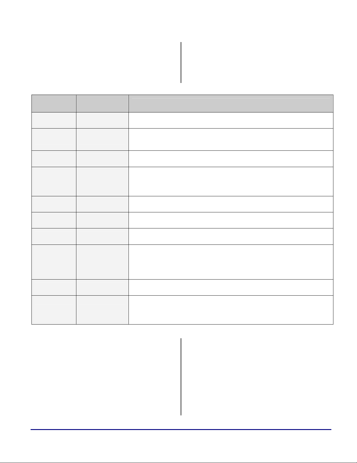
a
C/C++ source files. The three most important
sections to highlight first are what are defined as
seg_pmco, seg_dmda, and seg_pmda in the
SHARC world. These three section names map
directly to three equivalent section names for the
SHARC
Section Name
seg_pmco program
seg_dmda data1
seg_pmda data2
seg_stak
seg_heap M1Heap
TigerSHARC
Section Name
M1Stack & M2Stack for
ADSP-TS101.
M4Stack & M6Stack for
ADSP-TS20x.
This section, which must be in Program Memory (PM), holds code, and is required by some
functions in the C/C++ run-time library.
This section, which must be in Data Memory (DM), is the default location for global and
static variables and string literals, and is required by some functions in the C/C++ run-time
library.
This section, which must be in PM, holds PM data variables, and is required by some
functions in the C/C++ run-time library.
This section, which must be in DM, holds the run-time stack, and is required by the C/C++
run-time environment.
This section, which must be in DM, holds the default run-time heap, and is required by the
C/C++ run-time environment.
TigerSHARC processor. The table below shows
exactly which memory section in the SHARC
DSP maps to which memory section in the
TigerSHARC processor.
SHARC Usage Description
seg_init bsz_init
seg_rth Not Required
seg_init_code Not Required
seg_argv mem_argv
seg_ctdm ctor
Table 5. SHARC and TigerSHARC Default Memory Sections
This section, which must be in PM, holds system initialization data, and is required for
system initialization.
This section, which must be in the interrupt table area of PM, holds system initialization code
and interrupt service routines, and is required for system initialization.
This section, which must always be located in internal memory and contains library code that
modifies the interrupt latch registers (
number of SHARC DSPs means that it is unsafe for code located in external memory to
modify these registers, and this section is used to locate the affected library code in internal
memory without restricting the location of the rest of the library code.
This section, which contains the command-line arguments that are used as part of ProfileGuided Optimization (PGO).
This section, which contains the addresses of constructors that are called before the start of a
C++ program (such as constructors for global and static objects). This section must be
terminated with the symbol “
ensure this). It is required if compiling with C++ code.
One of the first steps to take when converting
code from SHARC DSPs to TigerSHARC
processors is altering the section names for any
sections defined in your assembly or source files.
This is not so important for C/C++ files, as by
default, all program and data defined as DM and
PM is mapped to the
program, data1, or data2
section automatically. If some data or code is
defined in C using the
SECTION{} commands,
IMASKP and IRPTL). A hardware anomaly on a
___ctor_NULL_marker” (the default .LDF files
the .LDF file must be modified accordingly to
accommodate this memory section.
Notice from Table 5 that there is no equivalent
seg_rth section for TigerSHARC processors.
This is because TigerSHARC processors have
specific memory-mapped registers for initializing
interrupt service routine vector addresses (unlike
SHARC DSPs, where an interrupt results in a
vector to a fixed address at the beginning of
SHARC® DSPs to TigerSHARC® Processors Code Porting Guide (EE-241) Page 37 of 64
Page 38
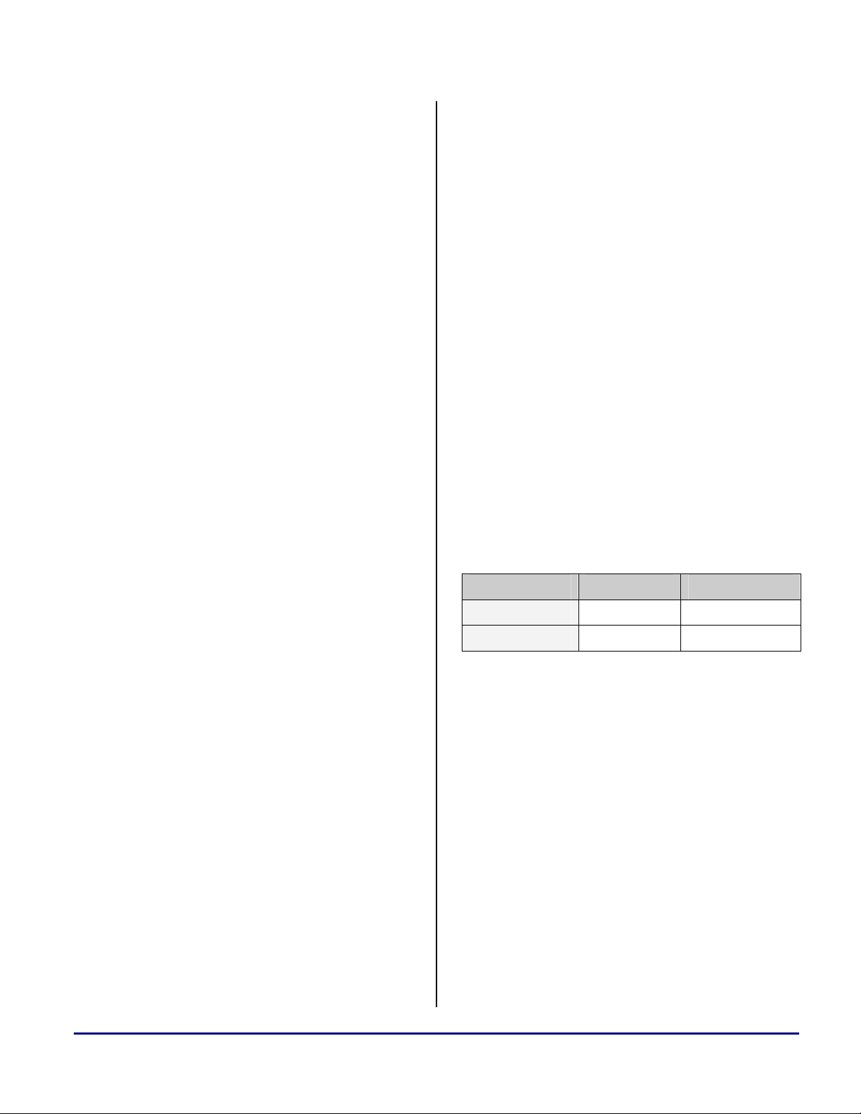
a
program memory). This is described in detail in
section 4.3.4 Interrupts. For detailed descriptions
of the various memory sections, refer to the
VisualDSP++ 3.5 Linker and Utilities Manual
for 32-bit Processors [10].
6.2 Register Classification
6.2.1 Callee Preserved Registers (“Preserved”)
The TigerSHARC processor run-time
environment requires that specific registers be
preserved and restored upon entry and exit from
an assembly routine. Registers J16 through J25,
K16 through K25, XR24 through XR31, and YR24
through
YR31 are preserved registers. If any of
these registers are used to convert your assembly
source, you must save them onto the stack and
restore them from the stack before and after use.
In sections 6.4.2 Function Prologue and 6.4.7
Function Epilogue, you will find that a function
entry and exit macro has been provided that
automatically saves and restores these preserved
registers. Although this macro may not be
required when converting your code, it has been
provided so you do not have to worry about
corrupting any of the preserved registers during
conversion of the source file. This is purely to
ease the conversion without taking into account
optimized execution.
6.3 Stack Frame Overview and Differences
6.3.1 Stack Pointer and Frame Pointer
In the SHARC run-time environment, the frame
pointer register is I6 and the stack pointer
register is I7. In the TigerSHARC run-time
environment the frame pointer register is J26 and
K26 for the J and K stack, respectively. The
frame pointers on the TigerSHARC processor are
stored in registers J27 and K27. The fact that the
TigerSHARC run-time environment defines two
stacks is one of the fundamental differences
between the SHARC DSP and TigerSHARC
processors run-time environments. Although the
TigerSHARC run-time environment defines two
stacks, the K stack is not used at present by the
compiler for storage of local variables. The K
stack, however, is freely available for use in
C/C++ callable assembly routines to speed up the
saving and restoring of registers. It also allows
for much faster context save and restores with
regard to interrupts. The C/C++ interrupt
dispatchers use the K stack to improve
performance.
Pointer SHARC TigerSHARC
Frame I6 J26, K26
Stack I7 J27, K27
Table 6. Frame & Stack Pointer Registers
6.2.2 Caller Save Registers (“Scratch”)
All other registers on the TigerSHARC processor
are “scratch” registers. Over function calls from
C to assembly and back again, these registers do
not need to be saved and restored upon entry and
exit. This, however, does not stand true for
calling assembly functions from assembly
functions while maintaining run-time
compatibility. You will need to take more care
and either push any required data onto the stack
before entering the next assembly routine or,
upon entry to the next assembly routine, save all
used registers and restore them upon exit. This
largely depends on the functionality of the called
assembly routines and how the application passes
data between the two routines.
SHARC® DSPs to TigerSHARC® Processors Code Porting Guide (EE-241) Page 38 of 64
One new term that you will come across in
relation to the TigerSHARC run-time
environment is the “effective Frame Pointer”
also known as the “eFP”. Upon entry to a
function, the current stack pointer is loaded into
the frame pointer register on TigerSHARC. This
is effectively the base (highest address) of the
frame, hence the term “eFP”. The “eFP” is then
offset by a negative value to give the “actual”
frame pointer “FP”. This offset allows for larger
negative references from the “eFP” for accessing
local variables than for positive offsets which are
used for arguments. This can result in the actual
frame pointer pointing off the end of the stack
but does not add any additional complexity or
overhead to the stack management.
Page 39

a
To summarize this point:
eFP equals j26+0x40 after the new frame has
been created
FP equals j26 after the new frame has been
created
6.3.2 Run-Time Stack
In both the SHARC and TigerSHARC run-time
environments, the stack grows towards smaller
addresses in memory. Figure 2 and Figure 3
show the structure of the stack for both the
SHARC and TigerSHARC family of processors.
Free Space SP
Current Stack Frame
Outgoing Arguments (if any)
Local Variables & Saved Registers
Return Address
Previous Functions Frame pointer
(I6)
Previous Functions Outgoing
FP
Arguments (Current Frames
Incoming Arguments)
Figure 2. SHARC Run-Time Stack
Free Space SP
Current Stack Frame
Outgoing Linkage (Current
Functions Stack and Frame
Pointers)
Outgoing Arguments (if any)
Local Variables and Temporaries
Return Address eFP
the figures where higher memory locations are
located at the bottom of the figure.
One very important difference to note between
the two run-time stacks is that the TigerSHARC
stack and frame pointers must be quad aligned
(address divisible by four) at all times. Failure to
adhere to this may result in exceptions if an
interrupt were to occur and the current stack and
frame pointers are not aligned correctly. This is
due to the interrupt dispatcher’s context save and
restore being performed on a quad word basis.
As can be seen from the two figures, the stack
frames for both the SHARC and TigerSHARC
run-time environments are very similar. The only
real difference is that an offset is applied to the
TigerSHARC eFP to give the actual FP and that
the FP on the SHARC and the eFP on the
TigerSHARC are offset slightly so that the FP on
the SHARC points to the previous function’s
frame pointer storage area and the eFP on the
TigerSHARC points to the return address
instead.
6.4 Code Conversion from SHARC DSPs to
TigerSHARC Processors
Now that the stack structures of the SHARC and
TigerSHARC processors have been introduced,
this document now concentrates on converting
the SHARC code of a C callable assembly
routine so the routine will comply with the
TigerSHARC run-time environment.
6.4.1 Procedure Call
On the SHARC processor a function call consists
of five steps:
Previous Functions Stack and
Frame pointers
Previous Functions Outgoing
Arguments (Current Frames
Incoming Arguments)
Figure 3. TigerSHARC Run-Time Stack
1. Load register
pointer (
I6).
2. Set the new frame pointer to the current stack
pointer (
I6 = I7).
3. Use a delayed branch instruction to pass
control to the called function.
R2 with the current frame
As the stack grows toward smaller memory
locations in memory, this has been reflected in
SHARC® DSPs to TigerSHARC® Processors Code Porting Guide (EE-241) Page 39 of 64
Page 40

a
4. Push the caller function’s frame pointer (R2)
onto the stack during the first delayed branch
slot.
5. Push the PC return address onto the stack
using the second delayed branch slot.
These five steps are automatically generated by
the compiler if the caller is a C function. For
ADSP-2106x/2116x DSPs, the following
instructions are generated, which when executed,
result in the creation of a new stack frame.
cjump my_function (DB);
dm(i7, m7) = r2;
dm(i7, m7) = pc;
Code 19. ADSP-2106x/2116x Procedure Call
6. Execution of the cjump instruction line
automatically carries out the first two
operations detailed above. However, this is
not true for the ADSP-21020. Execution of
the cjump instruction of the ADSP-21020
does not automatically save the frame pointer
to the register block or set the new frame
pointer equal to the previous frames stack
pointer; thus, the following code sequence is
required.
r2 = i6;
i6 = i7;
cjump my_function (DB);
dm(i7, m7) = r2;
dm(i7, m7) = pc;
Code 20. ADSP-21020 Procedure Call
On TigerSHARC processors, a function call
consists of three steps:
1. Call the function using the
CALL instruction.
2. Save J IALU stack and frame pointers to the
run-time stack.
3. Save K IALU stack and frame pointers to the
run-time stack.
All three of the above steps are carried out in a
single instruction line consisting of three
instructions as is shown below.
IF true, CALL my_function;
Q [j27 + 0X4] = j27:24;
Q [k27 + 0X4] = k27:24;;
Code 21. TigerSHARC Procedure Call
As mentioned earlier in this document, the end of
an instruction line is indicated with two
semicolons.
Effectively, the only difference with a
TigerSHARC function call is that the return
address has not already been saved to the runtime stack upon entry to the callee (this is
achieved on SHARC DSPs by using the delayed
branch feature) and that both the stack and frame
pointers are saved to the stack (instead of just the
frame pointer).
You may have noticed from the previous
example that although you are only required to
save the stack and frame pointer to the stack
from registers J27:26 and K27:26, four registers
are saved from each IALU. This requires no
extra cycle time and is required due to the
limitation that the stack and frame pointers must
always be quad-aligned as was mentioned in the
previous section. Saving and restoring these
additional two register from both the J and K
IALUs also provides additional functionality in
that copies of the K stack and frame pointers can
optionally be saved in J IALU and vice versa
allowing more flexibility as each IALU can
efficiently access both the C run-time stacks. For
simplicity, however, this method of stack access
is not covered in this EE-Note.
When calling another function from an assembly
function on ADSP-2106x/2116x or ADSP-21020
DSPs, the
call(x) macro as defined in
“asm_sprt.h” header file is used to maintain
compatibility with the run-time environment.
This macro expands to the code shown in Code
19 and Code 20. By creating a new macro to
include into the TigerSHARC project, function
calls from assembly routines can be easily
modified.
SHARC® DSPs to TigerSHARC® Processors Code Porting Guide (EE-241) Page 40 of 64
Page 41

#ifdef __ADSP21020__
#define ccall(x) r2=i6; i6=i7; jump (pc, x) (db); dm(i7,m7)=r2; dm(i7,m7)=PC
#else
#define ccall(x) cjump (x) (DB); dm(i7,m7)=r2; dm(i7,m7)=PC
Code 22. SHARC Function Call Macro
#define ccall(x) IF true, CALL x; q[j27+0X4]=j27:24; q[k27+0X4]=k27:24;
Code 23. TigerSHARC Function Call Macro
a
In Code 23, notice how the instruction
line ends in a single semicolon. This is
because the macro is used in the source
with an appending semicolon in the
SHARC project. Placing one semicolon
at the end of the TigerSHARC macro
results in two appending semicolons
when the macro call is replaced,
indicating the end of an instruction line.
6.4.2 Function Prologue
Upon entry to the assembly function on the
TigerSHARC, the first requirement is to create
the new stack frame for both the J and K stacks.
The new frame pointer is offset from the caller
functions stack pointer by -64. This is done for
both the J and K stacks in a single cycle.
The next step is to save the return address to the
stack. The return address is stored in the CJMP
register due to the execution of the
instruction. The
a post-modify instruction using the stack pointer,
CJMP register must be saved with
CALL
which at this point is equal to the effective frame
pointer (eFP).
To ease the conversion of SHARC code to
TigerSHARC code, it is recommended that any
compiler-reserved registers are saved to the
stack. This ensures that no compiler errors are
corrupted when mapping the SHARC registers to
the TigerSHARC registers as shown in Table 2.
On SHARC processors, two macros
(leaf_entry and entry) are defined in the
asm_sprt.h header file. For future compatibility
with the C/C++ run-time environment, all
assembly functions called from within a mixed
C/C++ and assembly project should have this
macro call as the very first instruction in the
assembly routine. Although at present, with
VisualDSP++ 3.5 for 32-bit Processors, this
macro is empty it provides an ideal opportunity
to use the macro for the TigerSHARC prologue
that is required upon entry to an assembly
function.
#define leaf_entry j26 = j27 - 0X40; k26 = k27 – 0x40;;\
j27 = j27 – 0x10 ; k27 = k27 - 0x10;; \
q[j27 + 12] = j23:20; q[k27 +12] = k23:20;; \
q[j27 + 8] = j19:16; q[k27 +8] = k19:16;; \
q[j27 + 4] = XR31:28; q[k27 +4] = YR31:28;; \
q[j27 += -4] = XR27:24; q[k27 += -4] = YR27:24;
#define entry j26 = j27 - 0X40; k26 = k27 – 0x40;;\
[j27 += –0x10] = cjmp ; k27 = k27 - 0x10;; \
q[j27 + 12] = j23:20; q[k27 +12] = k23:20;; \
q[j27 + 8] = j19:16; q[k27 +8] = k19:16;; \
q[j27 + 4] = XR31:28; q[k27 +4] = YR31:28;; \
q[j27 += -4] = XR27:24; q[k27 += -4] = YR27:24;
Code 24. TigerSHARC Function Prologue Macros
SHARC® DSPs to TigerSHARC® Processors Code Porting Guide (EE-241) Page 41 of 64
Page 42

a
The first instruction in the two epilogues shown
above sets the new frame pointer (FP) equal to
the current stack pointer (SP) minus the offset.
This is performed in both J and K stacks, thus
creating the new stack frames for the function.
The second instruction line in the macros saves
the return address to the stack (entry macro only)
and expands the stack pointers to allow for
saving all 32 compiler reserved registers (16
registers are saved to the J stack and 16 to the K
stack). The following instructions then store the
compiler reserved registers to the stacks.
Although with leaf functions it is generally not
necessary to save the return address to the stack,
a recommendation would be to make the
leaf_entry macro identical to the entry macro
in which the CJMP register is saved to the stack. It
requires no additional overhead and guarantees
that the return address can be restored safely.
6.4.3 Pushing Additional Data to the Stack
On TigerSHARC processors, all future saves to
the stacks that occur in the called assembly
function after the function prologue should be
performed using a post-modify store instruction
such as:
q[j27+= -4] = xr3:0;;
Code 25. Post-Modify Store to the J Stack
This way the registers will be saved to the stack
and the stack pointer will be modified to protect
them plus an additional four empty word
locations for the next save. Any data saved in a
memory address lower than currently pointed at
by the stack pointer is not protected and will
more than likely be lost.
Always point the stack pointer (J27) to
the next empty quad word on the top of
the stack. This is required in the event
that an interrupt occurs in which the
context saves use post-modify store
instructions.
On SHARC DSPs, data was placed onto the
stack using the puts macro defined in the
asm_sprt.h file.
#define puts dm(i7, m7)
Code 26. SHARC “puts” Macro
This macro can easily be re-defined to create
suitability for the TigerSHARC run-time
environment. Because TigerSHARC processors
have more than one stack, the following macros
can be used to provide greater flexibility.
#define puts [j27+=-4]
#define lputs l[j27+=-4]
#define qputs q[j27+=-4]
#define puts_jstack puts
#define lputs_jstack lputs
#define qputs_jstack qputs
#define puts_kstack [k27+=-4]
#define lputs_kstack l[k27+=-4]
#define qputs_kstack q[k27+=-4]
Code 27. TigerSHARC "puts" Macros
By default, when you perform code conversion,
the TigerSHARC processor’s J stack will always
be used when placing data onto the stack and
only single word (32-bit) data will be placed.
However this is not the most efficient way to
save data to the stack. This will become more
obvious when we look at the save_reg macro.
So, in a straight conversion, you need not alter
any of the source for placing data on to the stack;
however, more efficient macros have been
provided to allow you to place normal words,
long words, or quad words into either of the two
stacks, resulting in more efficient stack usage
and less overhead. This is due to the fact that up
to 8 words can be stored in a single cycle: 4 to
the J stack, and 4 to the K stack.
When using the puts macro on
TigerSHARC processors, add an
additional semicolon “;” to the end of
the macro call. The macro can be rewritten so this is not required; however,
this requires more alterations to the
source code.
SHARC® DSPs to TigerSHARC® Processors Code Porting Guide (EE-241) Page 42 of 64
Page 43

a
// SHARC // TigerSHARC // Efficient TigerSHARC
r0 = i0; puts = j5;; puts_jstack = j5; puts_kstack = k5;;
puts = r0;
r0 = i8; puts = k5;;
puts = r0;
puts = r8; puts = xr8;; lputs = xr9:8;;
puts = r9; puts = xr9;;
Code 28. Example Showing "puts" Macro Usage
The previous example shows how semicolons are
used for the macro calls. It also shows how
efficient the TigerSHARC processor can be. A
straight conversion requires four instructions
instead of eight because the J and K registers do
not need to be loaded to the compute blocks
before storing. This can then be brought down to
two instruction lines by bringing in the K stack
and the long store.
On SHARC DSPs, the save_reg macro pushes
all compute block registers (R0-R15) onto the
stack. This macro simply performs 16 put
operations to save the registers onto the stack.
The macro is shown below. A TigerSHARC
equivalent macro is also provided to save all 32
X compute block registers and Y compute block
registers to the stacks. The macro is optimized to
use quad loads and pushes the X compute block
registers on the J stack and the Y compute block
registers onto the K stack.
Notice that 16 cycles are required to save 16
registers on the stack for the SHARC DSPs;
however, TigerSHARC processors can save 64
registers to the stack in 8 cycles.
// SHARC
#define save_reg puts=r0;\
puts=r1;\
puts=r2;\
puts=r3;\
puts=r4;\
puts=r5;\
puts=r6;\
puts=r7;\
puts=r8;\
puts=r9;\
puts=r10;\
puts=r11;\
puts=r12;\
puts=r13;\
puts=r14;\
puts=r15
// TigerSHARC
#define save_reg qputs_jstack = xr3:0; qputs_kstack = yr3:0;;\
qputs_jstack = xr7:4; qputs_kstack = yr7:4;;\
qputs_jstack = xr11:8; qputs_kstack = yr11:8;;\
qputs_jstack = xr15:12; qputs_kstack = yr15:12;;\
SHARC® DSPs to TigerSHARC® Processors Code Porting Guide (EE-241) Page 43 of 64
Page 44

qputs_jstack = xr19:16; qputs_kstack = yr19:16;;\
qputs_jstack = xr23:20; qputs_kstack = yr23:20;;\
qputs_jstack = xr27:24; qputs_kstack = yr27:24;;\
qputs_jstack = xr31:28; qputs_kstack = yr31:28;
Code 29. SHARC and TigerSHARC "save_reg" Macros
a
6.4.4 Argument Passage
When converting a SHARC application to
TigerSHARC, retrieving arguments in an
assembly function called from a C function is
cleanly. This is because more registers are used
to pass parameters on TigerSHARC processors
than are used on SHARC DSPs, so not as many
variables are placed onto the stack.
little more complex. This does not convert
Argument passage
Argument word
Arg Word 1 r4 j4 r4 xr4 stack xr5:4
Arg Word 2 r8 j5 r8 xr5 stack xr7:6
Arg Word 3 r12 j6 r12 xr6 stack stack
Arg Word 4 stack j7 stack xr7 stack stack
Table 7. Registers used for Passing Arguments
On SHARC DSPs, multi-word arguments are
passed on the stack and any remaining arguments
are also passed on the stack. This is not quite the
same for TigerSHARC, in which multi-word
parameters are passed through registers xr7:4 if
there is enough room in these four registers. Any
further passed argument in which there is no
sufficient register space will be passed on the
stack. Once a parameter is passed on the stack,
all further parameters are also passed on the
stack.
Another point to note with TigerSHARC
processors involves
pointers and two floats are passed to a function,
this does not result in locating the pointers in J4
and J5 and the floats in XR4 and XR5. The floats
would actually be located in
A maximum of four arguments are passed
through registers regardless whether they are
if pointer or int float or double Double Word
SHARC TigerSHARC SHARC TigerSHARC SHARC TigerSHARC
passed through registers on SHARC DSPs, but
four are passed on TigerSHARC processors. This
requires slight modification to the way that
arguments are retrieved upon entry to the
assembly function.
On SHARC DSPs, the reads(x) macro is used
to read parameters of the stack, where “x” is the
number of parameter that you wish to retrieve.
For example, if five integers were passed to a
function, the first three integers would be passed
through registers and the fourth and fifth integers
j7:4 and xr7:4. If two
would be pulled off of the stack with reads(1)
reads(2), respectively.
and
The
reads(x) macro for SHARC DSPs is shown
below.
XR5, XR6, and XR7.
#define reads(x) dm(x, i6)
Code 30. SHARC "reads(x)" Macro
passed through a combination of IALU registers
or compute block registers. Another important
point to note is that only three arguments are
On SHARC processors, the passed parameters
are located in the addresses immediately
following the frame pointer for the callee. They
SHARC® DSPs to TigerSHARC® Processors Code Porting Guide (EE-241) Page 44 of 64
Page 45

a
are located in a higher address, which is the top
of the previous functions stack frame.
On TigerSHARC processors, this is slightly
different. The arguments are located at addresses
eFP+8 and higher, where eFP equals j27+0x40.
However, this does not mean that the fifth
parameter passed is located at eFP+8. Locations
eFP+8, eFP+9, eFP+10, and eFP+11 are used by
the compiler to store the variables that are passed
to a C function through the registers when debug
mode is enabled and optimization is disabled.
This code is generated automatically by the
compiler after the callee prologue when a C
function calls another C function.
To correctly retrieve the first variable passed to
the stack on TigerSHARC processors, you must
address memory location j27+0x4C. This is
equal to eFP+12.
The following TigerSHARC equivalent macro
has been defined to allow for correct retrieval of
variables from the stack.
on the stack would vary, depending on
previously passed values. For example, if two
integers were passed on the stack followed by the
long word, the third argument (the long word)
would be located at eFP+14. Whereas, if an
integer and two long words were passed, the
third argument would be located at eFP+16.
Therefore, it is not possible to create a single
macro to access the argument correctly under all
circumstances.
The use of the reads(x) macro on
TigerSHARC is guaranteed to work
only when reading single-word
arguments from the stack. If arguments
that are more than a single word (for
example, a long word) are passed, data
alignment must be taken into account;
this may cause the macro to read an
incorrect value. Care should be taken
during the argument retrieval on
TigerSHARC due to this requirement of
aligned data.
#define reads(x) [j26+ (75+x)];
Code 31. TigerSHARC "reads(x)" Macro
It is not possible to define a single macro that can
retrieve all long or quad values as their location
// Source for C file showing the function call.
extern void block_fir(dm float *, dm float *, pm float *, pm float *, int, int);
main()
{
int samples = N;
int taps = TAPS;
block_fir(input1, dline, coeffs, output1, samples, taps);
}
Code 32. C Source for Function Block FIR Function Call
_block_fir:
// The prologue is performed here followed by any saves to the stack
/**********************************************************************************
* Retrieve passed arguments
* The 3 pointers are passed through The 4 pointers are passed through
The following code example shows the retrieval
of arguments passed to a Block FIR function.
SHARC® DSPs to TigerSHARC® Processors Code Porting Guide (EE-241) Page 45 of 64
Page 46

* r4, r8 and r12. The output pointer registers j7:4. The number of
* is saved on stack. The number of samples and number of taps are
* samples and number of taps are integer values passed on the stack.
* integer values passed on the stack j4 = *input
* r4 = *input j5 = *dline
* r8 = *dline j6 = *coeffs
* r12 = *coeffs j7 = *output
* reads(1) = *output reads(1) = samples
* reads(2) = samples reads(2) = taps
* reads(3) = taps
**********************************************************************************/
// SHARC Example // TigerSHARC Example
/* input samples buffer setup */
i1 = r4; j1 = j4;;
/* dline pointer Circular buffer setup */
i0 = r8; j0 = j5;;
/* coeffs pointer Circular buffer setup */
i8 = r12; k0 = j6;;
r3 = reads(1); // Read output pointer
i9 = r3; // Write to DAG k5 = j7;;
r2 = reads(2); // N number of samples xr2 = reads(1);
r1 = reads(3); // Number of TAPS xr1 = reads(2);
a
Code 33. Example for Retrieval or Arguments Passed to Block FIR
6.4.5 Popping Data from the Stack
A macro is included for SHARC programmers to
the reverse order that it was pushed onto the
stack.
pop data back off of the C run-time stack. This
operation is performed with the gets(x) macro,
where “x” is an integer value used for reference
to the required data on the stack.
To allow for more efficient use of the two
TigerSHARC stacks, macros have been created,
allowing you to pop long words and quad words
from either of the two TigerSHARC stacks to
#define gets(x) dm(x, i7);
oppose the new macros that were presented for
pushing data onto the stack.
Code 34. SHARC "gets(x)" Macro
Popping data from the stack, unlike pushing data
#define gets(x) [j27+(4*x)];
#define lgets(x) l[j27+(4*x)];
#define qgets(x) q[j27+(4*x)];
#define gets_jstack(x) gets(x)
#define lgets_jstack(x) lgets(x)
#define qgets_jstack(x) qgets(x)
#define gets_kstack(x) [k27+(4*x)];
#define lgets_kstack(x) l[k27+(4*x)];
#define qgets_kstack(x) q[k27+(4*x)];
Code 35. TigerSHARC "gets(x)" Macro
For example, r0=gets(1) would pop the most
recently pushed value off of the stack.
r0=gets(4) pops the fourth value back off of the
stack. Generally, data is popped off the stack in
to the stack, does not modify the stack pointer.
Thus, the stack area in which the data was
retrieved is still protected. To use the memory
efficiently, modify the stack pointer after
popping data from the stack. This is achieved
with the
#define alter(x) modify(i7, x)
Code 36. SHARC "alter(x)" Macro
#define alter(x) j27=j27+(4*x);
#define alter_jstack(x) alter(x)
#define alter_kstack(x) k27=k27+(4*x);
alter(x) macro.
Code 37. TigerSHARC "alter(x)" Macro
SHARC® DSPs to TigerSHARC® Processors Code Porting Guide (EE-241) Page 46 of 64
Page 47

a
As can be seen, additional macros have been
provided for the TigerSHARC to allow
modification of both stacks freely. Also note that
the macro has been created in such a way that it
always alters by a quad word instead of a single
word as was required on SHARC processors.
Thus, on SHARC, alter(4) increases the stack
pointer (moves it down the stack) by four address
locations. The same operation on the
TigerSHARC would modify the stack pointer by
#define restore_reg r15=gets(1);\
r14=gets(2);\
r13=gets(3);\
r12=gets(4);\
r11=gets(5);\
r10=gets(6);\
r9 =gets(7);\
r8 =gets(8);\
r7 =gets(9);\
r6 =gets(10);\
r5 =gets(11);\
r4 =gets(12);\
r3 =gets(13);\
r2 =gets(14);\
r1 =gets(15);\
r0 =gets(16);\
alter(16)
16 locations, thus, no alteration to the original
SHARC source code is required.
The final macro with regard to popping data
from the stack is the restore_reg macro, which
restores registers
registers
XR0 to XR31 and YR0 to YR31 on the
R0 to R15 on the SHARC and
TigerSHARC. The macro automatically alters
the stack pointer after the registers have been
restored.
Code 38. "restore_reg" Macro on SHARC DSPs
#define restore_reg xr31:28 = qgets_jstack(1) yr31:28 = qgets_kstack(1);\
xr27:24 = qgets_jstack(2) yr27:24 = qgets_kstack(2);\
xr23:20 = qgets_jstack(3) yr23:20 = qgets_kstack(3);\
xr19:16 = qgets_jstack(4) yr19:16 = qgets_kstack(4);\
xr15:12 = qgets_jstack(5) yr15:12 = qgets_kstack(5);\
xr11:8 = qgets_jstack(6) yr11:8 = qgets_kstack(6);\
xr7:4 = qgets_jstack(7) yr7:4 = qgets_kstack(7);\
xr3:0 = qgets_jstack(8) yr3:0 = qgets_kstack(8);\
alter_jstack(8) alter_kstack(8)
Code 39. "restore_reg" Macro on TigerSHARC Processors
The following example shows the SHARC and
TigerSHARC equivalent for pushing data to and
popping data from the stack and modifying the
stack pointer accordingly.
A more optimized version is then provided using
both the J and K stacks in parallel.
Pay close attention to the use of the
semicolon in each of the versions in the
example below. Popping the data from
the stack is different from pushing data
onto the stack.
SHARC® DSPs to TigerSHARC® Processors Code Porting Guide (EE-241) Page 47 of 64
Page 48

// SHARC // TigerSHARC // Efficient TigerSHARC
/********* Push all registers and then some further data onto the stack **********/
save_reg; save_reg; save_reg;
r0 = i0; puts = j5;; puts_jstack = j5; puts_kstack = k5;;
puts = r0;
r0 = i8; puts = k5;;
puts = r0;
puts = r8; puts = xr8;; lputs = xr9:8;;
puts = r9; puts = xr9;;
/********** Pop all registers and then some further data from the stack **********/
r9 = gets(1); xr9 = gets(1); xr9:8 = lgets(1);
r8 = gets(2); xr8 = gets(2);
r0 = gets(3); k5 = gets(3); gets_jstack(2) gets_kstack(1);
i8 = r0;
r0 = gets(4); j5 = gets(4);
i0 = r0;
alter(4); alter(4); alter_jstack(2) alter_kstack(1);
restore_reg; restore_reg; restore_reg;
Code 40. Pushing and Popping the Stack Example
a
Parameter Returned SHARC TigerSHARC
int, long, char, short, pointer, and one-word structure
parameters
float R0 XR8
long double and two-word structure parameters
Results larger than two words
Table 8. Parameter Return Registers
6.4.6 Return Values
Table 8 details the registers used for SHARC
DSPs and TigerSHARC processors for returning
values back to a function.
On TigerSHARC processors, if the result is
larger than two words, the caller should allocate
space for the return result, and the address of the
parameter is passed through register J8. This
allows for efficient access to the required area in
the callee. The same address passed to the callee
in J8 should then be returned in J8 so the caller
can access the contents correctly.
R0 J8
R0, R1 where MSW is in R0
and LSW is in R1
R1 contains first location in
the block of memory
containing the results
6.4.7 Function Epilogue
XR8, XR9 where MSW is in
XR9 and LSW is in XR8
J8
Upon exit of the C callable assembly function,
the stack and frame pointers must be restored
from the stack before returning to the original
caller function.
#define leaf_exit i12=dm(m7,i6);\
jump (m14,i12) (db); i7=i6;\
i6=dm(0,I6)
#define exit leaf_exit
Code 41. ADSP-21020 and ADSP-21160 Function
Epilogue Macros
SHARC® DSPs to TigerSHARC® Processors Code Porting Guide (EE-241) Page 48 of 64
Page 49
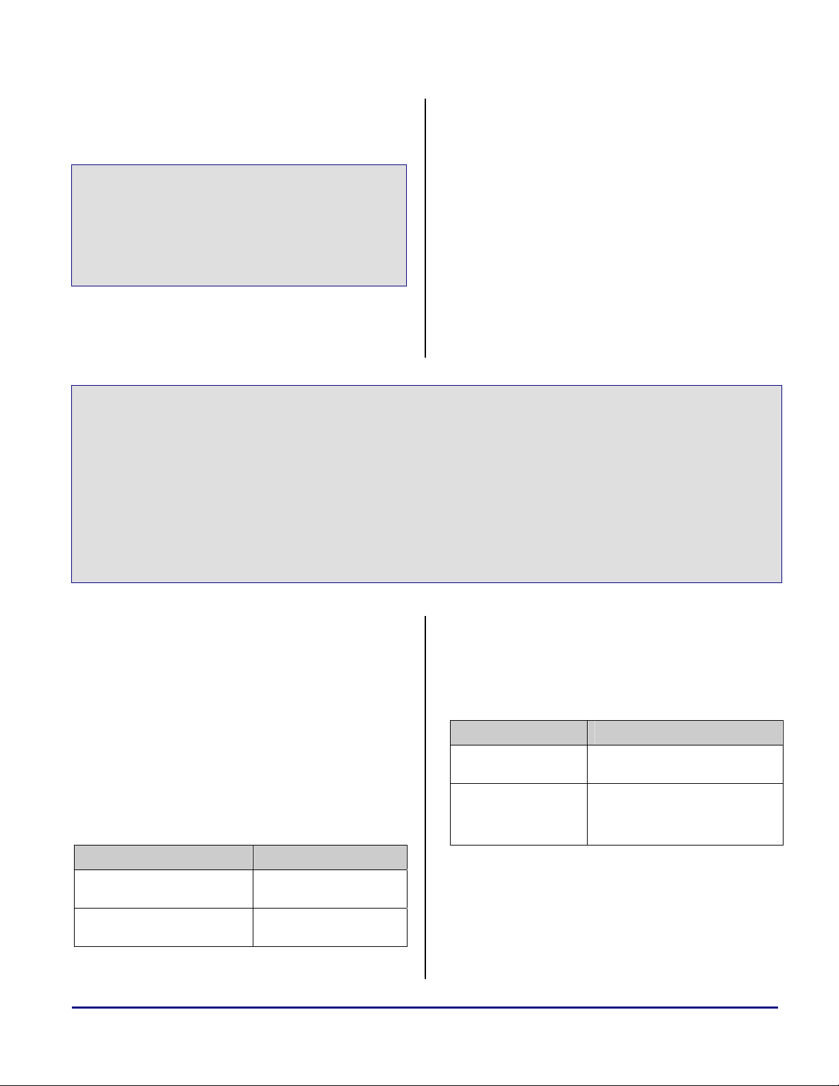
a
On SHARC DSPs, restoring the stack and frame
pointers and returning to the caller function is
performed with the leaf_exit and exit macros.
and frame pointers must be restored; then,
depending upon whether the assembly function is
a non-leaf function or a leaf function, return to
the address stored in the CJMP register or restore
#define leaf_exit i12=dm(m7,i6);\
jump (m14,i12) (db); i7=i6;\
i6=dm(0,i6)
#define exit leaf_exit
#define leaf_exit i12=dm(m7,i6);\
jump (m14,i12) (db); nop; RFRAME
#define exit leaf_exit
CJMP register from the stack and return to the
the
address. However, as the function prologue
macros that were provided previously also save
the compiler reserved registers to the stack, the
function epilogue must restore the compiler
reserved registers with the correct data from the
Code 42. SHARC Function Epilogue Macros
The function epilogue for TigerSHARC
stack. The TigerSHARC equivalent macros for
leaf_exit and exit are provided below.
processors works in a similar manner. The stack
#define exit XR27:24 = q[j27 + 4]; YR27:24 = q[k27 + 4];;\
XR31:28 = q[j27 + 8]; YR31:28 = q[k27 + 8];;\
j19:16 = q[j27 + 12]; k19:16 = q[k27 + 12];;\
j23:20 = q[j27 + 16]; k23:20 = q[k27 + 16];;\
cjmp = [j26+64];;\
cjmp(ABS)(np); j27:24 = q[j26+68]; k27:24 = q[k26+68];
#define leaf_exit XR27:24 = q[j27 + 4]; YR27:24 = q[k27 + 4];;\
XR31:28 = q[j27 + 8]; YR31:28 = q[k27 + 8];;\
j19:16 = q[j27 + 12]; k19:16 = q[k27 + 12];;\
j23:20 = q[j27 + 16]; k23:20 = q[k27 + 16];;\
cjmp(ABS)(np); j27:24 = q[j26+68]; k27:24 = q[k26+68];
Code 43. TigerSHARC Function Epilogue Macros
6.4.8 Using Mixed C/C++ and Assembly Naming
Conventions
The naming conventions for the SHARC and
TigerSHARC run-time environments are
identical.
In a C environment, if a variable is declared as
global in the C source, the variable is accessed
from the assembly source with the
.extern
keyword and by addressing the variable with a
preceding underscore character “
_” as shown
below.
C Source Assembly Source
// declared global
int c_var;
// declared global
void c_func;
Table 9. Accessing C from Assembly
.extern _c_var;
.extern _c_func;
The preceding underscore before the name is
also required when referencing a C function from
an assembly source. A similar method is applied
when accessing assembly variables or functions
from a C source.
Assembly Source C Source
.global
_asm_var;
.global
_asm_func;
_asm_func:
Table 10. Accessing Assembly from C
extern int asm_var;
extern void asm_func;
void asm_func();
Naming conventions for mixed C++ and
assembly source are the same for both SHARC
DSPs and TigerSHARC processors, however,
they differ from the mixed C and assembly
naming conventions just described. The table
SHARC® DSPs to TigerSHARC® Processors Code Porting Guide (EE-241) Page 49 of 64
Page 50
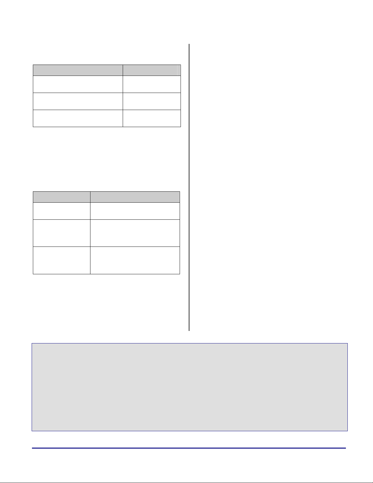
a
below shows how a C++ variable or function is
accessed from an assembly source.
C++ Source Assembly Source
int cpp_var; /*
declared global*/
void cpp_func(void); .extern
extern ″C″ void
cpp_func();
Table 11. Accessing C++ from Assembly
.extern
_cpp_var;
_cpp_func__Fv;
.extern
_cpp_func;
Note that the C++ function name mangling and
demangling depends on the passed parameters.
Table 11 shows only the easiest case with voids.
Table 12 shows how an assembly variable or
function is referenced from a C++ source.
Assembly Source C++ Source
.global
_asm_var;
.global
_asm_func;
_asm_func:
.global
asm_func;
asm_func:
Table 12. Accessing Assembly from C++
extern asm_var;
extern ″C″ void
asm_func;
extern ″asm″ asm_func;
As mentioned earlier, naming conventions are
identical for both TigerSHARC processors and
SHARC DSPs. For details on naming
conventions and examples, refer to the
VisualDSP++ 3.5 Compiler and Library Manual
for SHARC Processors [12] and the
VisualDSP++ 3.5 Compiler and Library Manual
for TigerSHARC Processors [11].
6.5 Heaps
A single heap is defined in the default Linker
Description Files and C run-time set-up files
used by the SHARC DSPs and the TigerSHARC
processors. In the SHARC DSP’s run-time
environment, the heap declaration must take
place in the seg_init.asm file. Each heap
specification in this file consists of:
8 bytes - ASCII heap name
2 bytes - unused
2 bytes - heap location
0x0001 - PM location
0xFFFF - DM location
6 bytes - zero
6 bytes - heap start address (in high-order 32
bits)
6 bytes - heap length (in high-order 32 bits)
With the default run-time setup on SHARC
DSPs, the single heap declared in seg_init.asm
is as shown below.
An example of the MEMORY section placement for
the heap in the Linker Description File is also
shown.
.global ___lib_heap_space;
.var ___lib_heap_space[5] =
0x7365675F6865, /* 'seg_he' */
0x6170FFFFFFFF, /* 'ap' */
0,
ldf_heap_space, /* start of default heap */
ldf_heap_length; /* size of default heap */
.___lib_heap_space.end:
/* Add more heap descriptions here */
.global ___lib_end_of_heap_descriptions;
.var ___lib_end_of_heap_descriptions = 0; /* Zero for end of list */
SHARC® DSPs to TigerSHARC® Processors Code Porting Guide (EE-241) Page 50 of 64
Page 51

___lib_end_of_heap_descriptions.end:
Code 44. SHARC Heap Declaration in "seg_init.asm"
MEMORY
{
seg_heap { TYPE(DM RAM) START(0x00058000) END(0x0005dfff) WIDTH(32) } }
}
SECTIONS
{
heap
{
ldf_heap_space = .;
ldf_heap_length = MEMORY_SIZEOF(seg_heap);
} > seg_heap
}
Code 45. SHARC Heap MEMORY Section Placement within the .LDF
a
The TigerSHARC processor heap declaration
takes place in the ts_hdr.asm file. The
TigerSHARC heap does not contain as much
information as that of a SHARC heap. All that is
required is a heap ID as shown below. The
MEMORY section placement of the heap in the
Linker Description File, however, is virtually the
same as that of the SHARC DSP’s MEMORY
section placement. The only difference being in
the way the MEMORY segment is defined.
// Create the heap descriptor table and describe the default heap, which is the
// first entry in the heap descriptor table. The ts_exit.asm file declares a label
// for the end of this table.
.section heaptab;
.global ___heaptab_start;
___heaptab_start:
.var = ldf_defheap_base; // start of default heap
.var = ldf_defheap_size; // size of default heap, unit==sizeof(char)
.var = 0; // id of default heap -- must be 0
Code 46. TigerSHARC Heap Declaration in "ts_hdr.asm"
MEMORY
{
M1Heap { TYPE(RAM) START(0x0008C000) END(0x0008C7FF) WIDTH(32) }
}
SECTIONS
{
heap
{
ldf_defheap_space = .;
ldf_defheap_length = MEMORY_SIZEOF(M1Heap);
} > M1Heap
}
Code 47. TigerSHARC Heap Memory Section Placement within the .LDF
SHARC® DSPs to TigerSHARC® Processors Code Porting Guide (EE-241) Page 51 of 64
Page 52

a
As can be seen from the previous two examples
of heap initialization on SHARC DSPs, the heap
has two identifiers:
Primary heap ID. This is the index of the
descriptor for that heap in the heap descriptor
table. The default heap is 0 with additional
user-defined heaps having primary IDs of 1,
2, 3, and so on.
A unique 8-letter name. With this name, the
heap ID can be obtained using the
heap_lookup_name() function call with the
TigerSHARC heaps, however, have only a
primary heap ID, with the default heap always
being 0 and additional user-defined heaps with
primary IDs of 1, 2, 3, and so on.
Both the SHARC and TigerSHARC run-time
environments support multiple heaps. The
examples below show the modifications required
to the Linker Description Files and the
seg_init.asm and ts_hdr.asm files to add an
additional heap to a different memory block.
name as its parameter.
global ___lib_heap_space;
.var ___lib_heap_space[5] =
0x7365675F6865, /* 'seg_he' */
0x6170FFFFFFFF, /* 'ap' */
0,
ldf_heap_space, /* start of default heap */
ldf_heap_length; /* size of default heap */
.___lib_heap_space.end:
/* Add more heap descriptions here */
.var ___lib_heap_space[5] =
0x7365675F6865, /* 'seg_he' */
0x6171FFFF0001, /* 'aq' */
0,
ldf_heaq_space, /* start of new heap */
ldf_heaq_length; /* size of new heap */
.___lib_heaq_space.end:
.global ___lib_end_of_heap_descriptions;
.var ___lib_end_of_heap_descriptions = 0; /* Zero for end of list */
___lib_end_of_heap_descriptions.end:
Code 48. SHARC Multiple Heap Declaration in "seg_init.asm"
MEMORY
{
seg_heap { TYPE(DM RAM) START(0x00058000) END(0x0005dfff) WIDTH(32) }
seg_heap2 { TYPE(PM RAM) START(0x0004f000) END(0x0004ffff) WIDTH(32) }
}
SECTIONS
{
heap
{
ldf_heap_space = .;
ldf_heap_length = MEMORY_SIZEOF(seg_heap);
} > seg_heap
Heap2
{
SHARC® DSPs to TigerSHARC® Processors Code Porting Guide (EE-241) Page 52 of 64
Page 53

ldf_heaq_space = .;
ldf_heaq_length = MEMORY_SIZEOF(seg_heap2);
} > seg_heap2
}
Code 49. SHARC Multiple Heap Memory Section Placement within the .LDF
// Create the heap descriptor table and describe the default heap, which is the
// first entry in the heap descriptor table. The ts_exit.asm file declares a label
// for the end of this table.
.section heaptab;
.global ___heaptab_start;
___heaptab_start:
.var = ldf_defheap_base; // start of default heap
.var = ldf_defheap_size; // size of default heap, unit==sizeof(char)
.var = 0; // id of default heap -- must be 0
.var = ldf_altheap_base; // start of alternate heap
.var = ldf_altheap_size; // size of alternate heap, unit==sizeof(char)
.var = 1; // id of alternate heap
Code 50. TigerSHARC Multiple Heap Declaration in "ts_hdr.asm"
MEMORY
{
M1Heap { TYPE(RAM) START(0x0008C000) END(0x0008C7FF) WIDTH(32) }
M2Heap { TYPE(RAM) START(0x0010C000) END(0x0010C7FF) WIDTH(32) }
}
SECTIONS
{
heap
{
ldf_defheap_space = .;
ldf_defheap_length = MEMORY_SIZEOF(M1Heap);
} > M1Heap
Heap2
{
ldf_altheap_space = .;
ldf_altheap_length = MEMORY_SIZEOF(M2Heap);
} > M2Heap
}
a
Code 51. TigerSHARC Processors Multiple Heap Memory Section Placement within LDF
Because TigerSHARC heaps have only a
primary heap ID and no unique name, some heap
management functions available in the SHARC
run-time environment are not available in the
TigerSHARC run-time environment. Table 13
details all the standard heap interface and
availability in the SHARC and TigerSHARC
run-time environments. Alternate heap interface
functions require an additional argument that
specifies the heap ID. These are suitable for use
in multithreaded applications such as VDK
projects.
alternate heap interface functions and their
SHARC® DSPs to TigerSHARC® Processors Code Porting Guide (EE-241) Page 53 of 64
Page 54
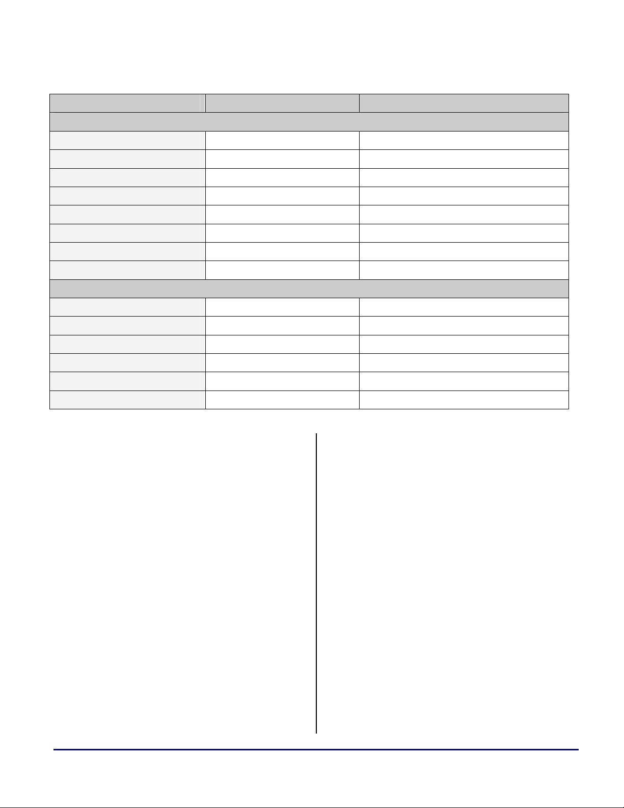
a
Heap Management Function Available on SHARC DSPs Available on TigerSHARC processors
Standard Interface
calloc Yes Yes
free Yes Yes
malloc Yes Yes
realloc Yes Yes
set_alloc_type Yes No
heap_switch Yes Yes
heap_init No Yes
heap_lookup_name Yes No
Alternate Interface
heap_calloc Yes Yes
heap_free Yes Yes
heap_malloc Yes Yes
heap_realloc Yes Yes
heap_lookup_name Yes No
heap_init No Yes
Table 13. SHARC and TigerSHARC Heap Management Functions
For functionality of the heap management
functions, refer to the VisualDSP++ 3.5
Compiler and Library Manual for SHARC
Processors [12] and the VisualDSP++ 3.5
Compiler and Library Manual for TigerSHARC
Processors [11].
section and the previous sections of the EE-Note.
For completeness and as a reference, some
examples appear in section 7 Algorithm Code
Examples.
By following the guidelines and using the
macros detailed in this section, the operation of
the TigerSHARC C/C++ run-time environment
6.6 Summary
The information described in this section is
provided to aid software developers in porting
C/C++ or mixed C/C++ and assembly
should be of little concern to the software
programmer during the original conversion
stage, significantly speeding up the upgrade
process.
applications from the SHARC family of DSPs to
the TigerSHARC family of processors.
The macros defined throughout this section are
included in the
.ZIP file provided along with this
document, which includes example code,
showing the conversion of a mixed C and
assembly block FIR filter from the ADSP-21160
SHARC DSP to the ADSP-TS201 TigerSHARC
processor using the techniques described in this
SHARC® DSPs to TigerSHARC® Processors Code Porting Guide (EE-241) Page 54 of 64
Page 55

a
7 Algorithm Code Examples
SHARC-to-TigerSHARC Conversion Examples,
are available in the .ZIP file provided along with
This section provides a set of SHARC source
this document.
code examples and their TigerSHARC
equivalents, explaining the differences between
the two architectures. In order to be able to cover
a wide variety of examples, SISD and SIMD
programming examples are examined.
Additionally, different levels of optimization for
more efficient TigerSHARC source code is
shown.
7.1 DFT
The following example illustrates the
implementation of a discrete Fourier transform
(DFT) for the ADSP-21062 SHARC DSP along
with its ADSP-TS201 TigerSHARC processor
equivalent.
These source code examples, along with the
programming examples discussed in section 5
// SHARC (ADSP-21062) // TigerSHARC (ADSP-TS201)
// Register definitions
#include "def21060.h" #include "defts201.h"
#define N 64 #define N 64
// Declare variables in data memory
.SECTION/DM seg_dmda; .SECTION data1;
.VAR input[N]= "test64.dat"; .VAR input[N]= "test64.dat";
.VAR real[N]; .VAR real[N];
.VAR imag[N]; .VAR imag[N];
// Declare variables in program memory
.SECTION/PM seg_pmda; .SECTION data2;
.VAR sine[N]= "sin64.dat"; .VAR sine[N]= "sin64.dat";
// The reset vector
.SECTION/PM seg_rth;
NOP;
NOP;
NOP;
JUMP start;
// DFT routine
.SECTION/PM seg_pmco; .SECTION program;
start: M1=1; start: j13=1;;
M9=1; k13=1;;
// Input buffer is circular
B0=input; JB0=input;;
I0=B0; J0=JB0;;
L0=N; JL0=N;;
I1=imag; j5=imag;;
L1=0;
// Enable Circular buffer
Bit set mode1 CBUFEN;
CALL dft (DB);
I2=real; j6=real;;
SHARC® DSPs to TigerSHARC® Processors Code Porting Guide (EE-241) Page 55 of 64
Page 56

L2=0; call dft;;
end: jump end;; end: jump end;;
dft: B8=sine; dft: KB0=sine;;
I8=B8; K0=KB0;;
L8=N; KL0=N;;
B9=sine; KB1=sine;;
I9=sine+N/4; K1=sine+N/4;;
L9=N; KL1=N;;
I10=0; K2=0;;
L10=0;
F15=0; xr15=0;;
LCNTR=N, DO outer UNTIL LCE; LC0=N;;
F8=PASS F15, M8=I10; outer: xfr8=PASS r15; K12=K2;;
F9=PASS F15, F0=DM(I0,M1), xfr9=PASS r15; xr0=CB[j0+=j13];
F5=PM(I9,M8); xr5=CB[K1+=K12];;
F12=F0*F5, F4=PM(I8,M8); xfr12=r0*r5; xr4=CB[k0+=k12];
LC1=N-1;;
LCNTR= N-1 , DO inner UNTIL LCE;
F13=F0*F4, F9=F9+F12, inner: xfr13=r0*r4; xfr9=r9+r12;
F0=DM(I0,M1),F5=PM(I9,M8); xr0=CB[j0+=j13]; xr5=CB[k1+=k12];;
inner: F12=F0*F5, F8=F8-F13, if NLC1E, jump inner; xfr12=r0*r5;
F4=PM(I8,M8); xfr8=r8-r13; xr4=CB[k0+=k12];;
F13=F0*F4, F9=F9+F12; xfr13=r0*r4; xfr9=r9+r12;;
F8=F8-F13, DM(I2,M1)=F9; xfr8=r8 - r13; [j6+=j13]= xr9;;
MODIFY(I10,M9); K2=k2+k13;;
outer: DM(I1,M1)=F8; if NLC0E, jump outer;[j5+=j13]=xr8;;
RTS; cjmp(ABS);;
// Cycle count = 8673 (@40MHz) // Cycle count = 17468 (@600MHz)
// Execution time = 0.217 msecs // Execution time = 0.029 msecs
// SHARC to TigerSHARC Performance increase = x7.5
a
Code 52. SHARC and TigerSHARC DFT Example
One of the very first things to point out in the
SHARC example code is the fact that this is a
SISD example.
Therefore, and just for simplicity and to keep the
two examples aligned, the TigerSHARC
equivalent code is also SISD (i.e., only CBx
register, and simply as R15, when used as the
source.
As can be seen in Code 52, several source code
lines have been highlighted. The following
sections explain what the different highlighted
lines mean.
registers are used). Refer to section 7.2 FIR for a
SIMD example.
7.1.1 MEMORY Sections
Refer to section 6.1 Memory .SECTION and
Also note that a TigerSHARC floating point
number, represented in SHARC code as
represented as
xFR15, when used as a destination
F15, is
SECTION{} Names, which explains the
differences and similarities between the SHARC
and TigerSHARC section names and memory
map.
SHARC® DSPs to TigerSHARC® Processors Code Porting Guide (EE-241) Page 56 of 64
Page 57

a
As can be seen in Code 52, the “DM” and “PM”
qualifiers are no longer needed. The section
names (i.e., seg_pmco and program) must matc h
those declared in the Linker Description File
LDF).
(.
7.1.2 Reset Interrupt Vector
The definition of a reset interrupt vector is no
longer needed in TigerSHARC. Refer to section
4.3.4 Interrupts for more details.
7.1.3 Call DB
As previously explained, delayed branches (db)
are not supported by TigerSHARC processors.
Therefore, place the CALL DFT instruction as the
very last instruction before the DFT routine is to
be called. For more details, please refer to
section 4.3.1 Instruction Pipeline.
7.1.4 Data Addressing
As explained in section 4.2 Data Addressing, the
following register map is used for the DAGs and
IALUs:
Similarly, enabling circular buffer mode in
SHARC DSPs is not required for TigerSHARC
processors.
As indicated in Code 52, ADSP-TS201
7.2 FIR
The following examples illustrate the
implementation of a Finite Impulse Response
(FIR) filter for the ADSP-21160 SHARC DSP
along with its ADSP-TS201 TigerSHARC
processor equivalent.
Different levels of optimization are discussed
throughout this section. Similar to the other
examples, the FIR code can also be found in
.ZIP file provided along with this document.
TigerSHARC processors offer 7.5 times
faster execution time.
The TigerSHARC code illustrated above
can be further optimized, and therefore,
higher efficiency can still be achieved.
M1Öj13, M9Ö k13
B0ÖJB0, I0ÖJ0, L0ÖJL0
I1Öj5, I2Öj6, I10ÖK2
B8ÖKB0, I8ÖK0, L8ÖKL0
B9ÖKB1, I9ÖK1, L9ÖKL1
In this example, note that the SHARC I0, I8,
and I9 registers are used as circular buffers. As
previously explained, the
dedicated for circular buffers in TigerSHARC.
Also, be aware that in SHARC, length registers
(e.g., L1) must be initialized to zero to indicate
that the buffer is linear and not circular. This,
however, is not needed in TigerSHARC.
Therefore, instructions such as
be translated and can be simply ignored.
// SHARC (ADSP-21160) // TigerSHARC (ADSP-TS201)
#include "def21160.h" #include "defts201.h"
#include "asm_sprt.h" #include "asm_sprt_TS.h"
J/K3-0 registers are
L1=0; need not
7.2.1 FIR One-to-One Conversion
Code 53 shows a direct conversion of the
SHARC code to its TigerSHARC equivalent
without optimization. This example is a simple
one-to-one translation for functionality purposes
only, where no advantage of the TigerSHARC
architecture have been taken.
Additionally, this floating-point block FIR
source code has been made C callable. Some of
the macros for saving and restoring to and from
the stack have been added simply to show how
the TigerSHARC macros explained in section 6
C Run-Time Environment can be implemented
without much alteration of the code.
Note that a more optimized version of the block
FIR code is introduced later.
SHARC® DSPs to TigerSHARC® Processors Code Porting Guide (EE-241) Page 57 of 64
Page 58

.section/pm seg_pmco; .section program;
_block_fir:
leaf_entry;
/* save all register block to stack */
save_reg;
/* save some other registers to stack */
r0 = i0;
puts = r0; puts = j0;;
r0 = i1;
puts = r0; puts = j5;;
r0 = i8;
puts = r0; puts = k0;;
r0 = i9;
puts = r0; puts = k5;;
/* reads N and TAPS from the stack */
r3 = reads(1); // Output pointer
r2 = reads(2); xr2 = reads(1); // N number of samples
r1 = reads(3); xr1 = reads(2); // Number of TAPS
/* dline pointer CB setup */
/* second parameter passed stired in r8 */
i0 = r8; b0 = r8; l0 = r1; j0 = j5;; jb0 = j0;; jl0 = xr1;;
/* input samples buffer setup */
/* first parameter passed stored in r4 */
i1 = r4; b1 = r4; l1 = 0x0; j5 = j4;;
/* coeffs pointer CB setup */
/* third parameter passed stored in r12 */
i8 = r12; b8 = r12;l8 = r1; k0 = j6;; kb0 = k0;; kl0 = xr1;;
/* output buffer setup */
i9 = r3; b9 = r3; l9 = 0x0; k5 = j7;;
/* Modifier values */
m0 = 0; j12 = 0;;
m1 = 1; j13 = 1;;
m2 = -1; j14 = -1;;
m3 = 2; j15 = 2;;
m9 = 2; k13 = 2;;
m10= 1; k14 = 1;;
/* Zero the first output result */
f8 = 0.0; xr8 = 0;;
/* Circular Buffer Enable */
bit set MODE1 CBUFEN;
nop;
/* move pointer to delay[1] */
s0 = dm(i0, m1); yr0 = CB [j0+=j13];;
/* load s0 with the value of delay[1] for SIMD store, move pointer to delay[0] */
s0 = dm(i0, m2); yr0 = CB [j0+=j14];;
a
SHARC® DSPs to TigerSHARC® Processors Code Porting Guide (EE-241) Page 58 of 64
Page 59

/* r1 = taps/2 due to SIMD mode */
r1 = lshift r1 by -1; xr1 = lshift r1 by -1;;
/* 3 macs outside of fir mac loop */
r3 = 3; xr3 = 3;;
/* r3 = taps/2 - 3 for fir mac loop counter */
r3 = r1 - r3; xr3 = r1 - r3;;
/* SIMD Mode Enable */
bit set MODE1 PEYEN;*/
/* SIMD not in effect until next cycle */
/* read one sample from INPUT[i] */
r0 = dm(i1,m1); xr0 = [j5+=j13];;
/* read 2 coeffs */
f4 = pm(i8,m9); yxr4 = CB l[k0+=k13];;
/* outer loop - sample loop */
lcntr = r2, do main_fir until lce; LC0 = xr2;;
/* transfer new sample and last new sample to delayline */
main_fir:
dm(i0,m3)=f0; CB [j0+=j13] = xr0;;
CB [j0+=j13] = yr0;;
/* samples * coeffs, read 2 samples, read 2 coeffs */
f8=f0*f4, f0=dm(i0,m3), fr8 = r0*r4; xr0 = CB [j0+=j13];
f4=pm(i8,m9); yxr4 = CB l[k0+=k13];;
yr0 = CB [j0+=j13];;
/* samples * coeffs, read 2 samples, read 2 coeffs */
f12=f0*f4, f0=dm(i0,m3), fr12 = r0*r4; xr0 = CB [j0+=j13];
f4=pm(i8,m9); yxr4 = CB l[k0+=k13];;
yr0 = CB [j0+=j13];;
/* FIR loop */
lcntr=r3, do macs until lce; LC1 = xr3;;
/* samples * coeffs, accum, read 2 samples, read 2 coeffs */
macs:
f12=f0*f4, f8=f8+f12, fr12 = r0*r4; fr8 = r8+r12;
f0=dm(i0,m3), f4=pm(i8,m9); xr0 = CB [j0+=j13];
yxr4 = CB l[k0+=k13];;
if NLC1E, jump macs; yr0 = CB [j0+=j13];;
/*samples*coeffs,accum,load s0 with delay[1] for SIMD, move pointer to delay[0]
f12=f0*f4, f8=f8+f12, s0=dm(i0,m2); fr12 = r0*r4; fr8 = r8+r12;
yr0 = CB [j0+=j14];;
/* final SIMD accum, read new sample into s10 */
f8=f8+f12, s10=dm(i1,m1); fr8 = r8+r12; yr10 = [j5+=j13];;
/* move PEy total into PEx register file */
r12=s8; xr12 = yr8;;
/* last accum, read sample into s0 for first MAC of next sample, read 2 coeffs */
f8=f8+f12, f4=pm(i8,m9); fr8 = r8+r12; yxr4 = CB l[k0+=k13];;
a
SHARC® DSPs to TigerSHARC® Processors Code Porting Guide (EE-241) Page 59 of 64
Page 60

/* place new sample from s10 in f0 without corrupting s0, swaps f0 and s10 only */
f0 <-> s10; xr0 = yr10;;
/* write result to OUTPUT[i] */
main_fir: pm(i9,m10)=f8; if NLC0E, jump main_fir; [k5+=k14] = xr8;;
/* Circular Buffer Disable, SIMD Mode Disable */
bit clr MODE1 CBUFEN | PEYEN;
/* restore registers from stack */
r0 = gets(1);
i9 = r0; k5 = gets(1);
r0 = gets(2);
i8 = r0; k0 = gets(2);
r0 = gets(3);
i1 = r0; j5 = gets(3);
r0 = gets(4);
i0 = r0; j0 = gets(4);
/* modify stack pointer */
alter(4); alter(4);
/* restore register block from stack */
restore_reg;
_block_fir.END: leaf_exit;
// Cycle count = 5101 (@100MHz) // Cycle count = 14353 (@600MHz)
// Execution time = 0.051 msecs // Execution time = 0.0239 msecs
// SHARC to TigerSHARC Performance increase = x2.13
a
Code 53. Floating Point Block FIR One-to-One Conversion
One of the very first things to point out in the
SHARC example code is that this is a SIMD
example.
Even if some of the above SHARC and
The highlighted sections from the outer loop –
sample loop
instruction in
the SIMD accesses performed in the SHARC
DSP and how they have been in implemented on
the TigerSHARC processor.
From the
the delay line is not always aligned on a dual
address, so we are unable to perform SIMD
accesses on the TigerSHARC. There are many
ways to overcome this problem, such as copying
the delay line to another memory block and then
TigerSHARC instructions differ, they
are not highlighted if they have already
been explained in a previous example.
label to the last accumulate
main_fir in Code 53 are related to
outer loop – sample loop line on,
using a J and K pointer to load two words in a
single instruction.
Another method is to implement quad loads
using the data alignment buffer on TigerSHARC.
In this original conversion we simply perform
two loads instead of a SIMD load for the delay
line, each having a modifier of 1 instead of 2. A
SIMD load, however, is performed for all
coefficient accesses as the pointer in this buffer
is always aligned.
The remaining highlighted sections show the use
of macros for saving and storing registers as well
as for the stack handling. These lines have been
added so that the code is fully C callable. For
more details, refer to section 6 C Run-Time
Environment.
As indicated in Code 53, the ADSP-
TS201 TigerSHARC processor offers
2.1 times faster execution time.
SHARC® DSPs to TigerSHARC® Processors Code Porting Guide (EE-241) Page 60 of 64
Page 61

The TigerSHARC code illustrated above
can be further optimized, and therefore,
higher efficiency can still be achieved.
7.2.2 Optimized FIR
Code 54 shows an optimized implementation of
the block FIR filter discussed in the previous
section.
a
// TigerSHARC (ADSP-TS201)
#include <defts201.h>
#include "asm_sprt_TS.h"
/* program memory code */
.section program;
_block_fir:
leaf_entry;
/* save all register block to stack */
save_reg;
/* save some other registers to stack */
puts_jstack = j0; puts_kstack = k0;;
puts_jstack = j5; puts_kstack = k5;;
xr17 = reads(1); // N number of samples
xr16 = reads(2); // Number of TAPS
/* dline pointer CB setup */
/* second parameter passed stired in r8 */
j0 = j5;; jb0 = j0;; jl0 = xr16;;
/* Create new pointer in dline for storing new input */
j1 = j0;; jb1 = j0;; jl1 = xr16;;
/* input samples buffer setup */
/* first parameter passed stored in r4 */
j5 = j4;;
/* coeffs pointer CB setup */
/* third parameter passed stored in r12 */
k0 = j6;; kb0 = k0;; kl0 = xr16;;
/* output buffer setup */
k5 = j7;;
/* Setup modify registers for arrays, calculate loop counts, prime the DAB and load
first samples and coefficients */
j12 = 0; r3:0 = DAB q[j0+=0]; xr16 = lshift r16 by -1;;
j13 = 1;;
j14 = -1; r3:0 = DAB q[j0+=4];;
j15 = 2;;
xr18 = 4;;
k13 = 2;r3:0 = DAB q[j0+=4];;
xr18 = r16 - r18; LC0 = xr17;;
k14 = 1; xr0 = [j5+=j13];;
xr18 = lshift r18 by -1; yxr5:4 = CB q[k0+=4];;
/* transfer new sample to delay line and reset second accum register */
main_fir: CB [j1+=j14] = xr0; r9 = 0;;
/* Set inner loop counter */
LC1 = xr18;;
SHARC® DSPs to TigerSHARC® Processors Code Porting Guide (EE-241) Page 61 of 64
Page 62

/* samples * coeffs, resets second MAC register */
xfr8 = r0*r4; yfr8 = r2*r4; r13 = 0;;
/* samples * coeffs, read 4 samples, read 4 coeffs */
xfr12 = r1*r5; yfr12 = r3*r5; yxr5:4 = CB q[k0+=4]; r3:0 = DAB q[j0+=4];;
/* FIR loop */
macs: nop;;
xfr12 = r0*r4; yfr12 = r2*r4; fr8 = r8+r12;; /* samples * coeffs, accum */
xfr13 = r1*r5; yfr13 = r3*r5; fr9 = r9+r13;; /* samples * coeffs, accum */
/* loop, load 4 coeffs, load 4 samples*/
if NLC1E, jump macs; yxr5:4 = CB q[k0+=4]; r3:0 = DAB q[j0+=4];;
/* samples * coeffs, accum, reset pointer to new dline[0] */
xfr12 = r0*r4; yfr12 = r2*r4; fr8 = r8+r12; j0 = j0 - 5 (cb);;
/* samples * coeffs, accum, first prime of DAB */
xfr13 = r1*r5; yfr13 = r3*r5; fr9 = r9+r13; r3:0 = DAB q[j0+=0];;
/* accum, read new sample into s10 */
fr8 = r8+r12; yr10 = [j5+=j13];;
/* accum second results and second prime of DAB, move Y accum to X */
fr9 = r9+r13; r3:0 = DAB q[j0+=4]; xr12 = yr8;;
/* move Y accum into X register file */
xr13 = yr9;;
/* Accum results of Y and X, load 4 coefficients*/
fr8 = r8+r12; yxr5:4 = CB q[k0+=4];;
/* Accum results of Y and X */
fr9 = r9+r13;;
/* Final accum, load first 4 samples*/
fr8 = r8+r9; r3:0 = DAB q[j0+=4];; /* prime the DAB again */
/* write result to OUTPUT[i], load new sample to X as dline has not been updated*/
if NLC0E, jump main_fir; [k5+=k14] = xr8; xr0 = yr10;;
/* restore registers from J and K stack */
k5 = gets_kstack(1) j5 = gets_jstack(1);
k0 = gets_kstack(2) j0 = gets_jstack(2);
/* modify J and K stack pointers */
alter_jstack(2) alter_kstack(2);
/* restore register block from stack */
restore_reg;
_block_fir.END: leaf_exit;
// Cycle count = 5101 (@100MHz) // Cycle count = 9211 (@600MHz)
// Execution time = 0.051 msecs // Execution time = 0.0153 msecs
// SHARC to TigerSHARC Performance increase = x3.3
a
Code 54. Optimized Floating Point Block FIR
SHARC® DSPs to TigerSHARC® Processors Code Porting Guide (EE-241) Page 62 of 64
Page 63

a
The following optimizations are performed in the
above example:
Re-ordering of instructions to make more
parallel (software pipelining). This makes
much better use of the 128-bit instruction line
to reduce a number of stalls and decrease the
number of instruction lines in the example.
Using quad access for both delay line reads
and coefficient reads (vectorization). The
dline reads are performed using distributed
quad loads through the DAB.
Also, the removal of some instructions was
performed after the initial conversion to the
TigerSHARC. These did not affect
functionality but were simply not efficient
and redundant.
There is still a stall in the inner loop. This is
due to a compute block load dependency.
This can be overcome by doubling up on the
contents of the loop (loop un-rolling) so eight
dline samples and eight coefficients are
loaded every iteration.
Then compute instructions interleaved
(interleaving) so there are always two cycles
between loading the registers and using the
registers in the multiply and accumulate
instructions. This doubles the cycle count for the
loop but halves the amount of times the inner
loop is executed and removes the stall.
8 Conclusion
This engineer-to-engineer note provides a step-
by-step guide on how to port SHARC code to its
TigerSHARC equivalent. Major differences
between the two architectures and several code
examples have been discussed to help existing
SHARC customers minimize the time and effort
involved in translating code for the TigerSHARC
processors.
As already highlighted throughout this
document, porting code from the SHARC DSP
family to the TigerSHARC processor family can
be done in many different ways, depending on
the selected register map. For this EE-note, the
selected scheme is shown in Table 2.
This is not the only way of doing it, and it may
not produce the most efficient TigerSHARC
code for all cases. It will, however, help you
translate source code quickly so that it runs on
TigerSHARC platforms.
In conclusion, it has been shown that the
TigerSHARC processor family is, due to its
extremely high-performance core, large on-chip
memory, and increased feature set, the ideal
device for upgrading existing SHARC systems
looking for a boost in performance and an overall
system cost reduction.
For a fully optimized example of the floating
point block FIR, refer to the code examples
included with the VisualDSP++ installation.
As indicated in Code 54, ADSP-TS201
SHARC® DSPs to TigerSHARC® Processors Code Porting Guide (EE-241) Page 63 of 64
TigerSHARC processors offer 3.3 times
faster execution time.
As mentioned above, this TigerSHARC
example can be further optimized, and
therefore, higher efficiency can be
achieved.
Page 64

a
9 References
[1] ADSP-2106x SHARC User’s Manual. Rev.2.1, March 2004. Analog Devices, Inc.
[2] ADSP-21160 SHARC DSP Hardware Reference. Rev.3.0, November 2003. Analog Devices, Inc.
[3] ADSP-21160 SHARC DSP Instruction Set Reference. Rev.2.0, November 2003. Analog Devices, Inc.
[4] ADSP-21161 SHARC DSP Hardware Reference. Rev.3.0, May 2002. Analog Devices, Inc.
[5] ADSP-TS101TigerSHARC Processor Hardware Reference. Rev.1.1, May 2004. Analog Devices, Inc.
[6] ADSP-TS101 TigerSHARC Processor Programming Reference. Rev.1.0, January 2002. Analog Devices, Inc.
[7] ADSP-TS201 TigerSHARC Processor Hardware Reference. Rev.0.2, September 2003. Analog Devices, Inc.
[8] ADSP-TS201 TigerSHARC Processor Programming Reference. Rev.0.1, June 2003. Analog Devices, Inc.
[9] Considerations for Porting Code from the ADSP-TS101S TigerSHARC Processor to the ADSP-TS201S TigerSHARC
Processor (EE-205). Rev 1, September 2003. Analog Devices, Inc.
[10] VisualDSP++ 3.5 Linker and Utilities Manual for 32-bit Processor. Rev.1.0, March 2004. Analog Devices, Inc.
[11] VisualDSP++ 3.5 Compiler and Library Manual for TigerSHARC Processors. Rev.1.1, March 2004.
Analog Devices, Inc.
[12] VisualDSP++ 3.5 Compiler and Library Manual for SHARC Processors. Rev.4.1, March 2004. Analog Devices, Inc.
[13] VisualDSP++ 3.5 Assembler and Preprocessor Manual for TigerSHARC Processors. Rev.1.1 March 2004.
Analog Devices Inc.
10 Document History
Revision Description
Rev 1 – July 14, 2004
by Andrew Caldwell
and Maikel Kokaly-Bannourah
Initial Release
SHARC® DSPs to TigerSHARC® Processors Code Porting Guide (EE-241) Page 64 of 64
 Loading...