

Page 1

Engineer-to-Engineer Note EE-183
a
Technical notes on using Analog Devices DSPs, processors and development tools
Contact our technical support at dsp.support@analog.com and at dsptools.support@analog.com
Or vi sit our o n-li ne r esou rces htt p:/ /www.analog.com/ee-notes and http://www.analog.com/processors
Rational Sample Rate Conversion with Blackfin® Processors
Contributed by Jeff Sondermeyer, Senior DSP FAE Rev 4 – March 18, 2004
Introduction
The process of converting the sampling rate of a signal
from one rate to another is called sampling rate conversion
(or SRC). This technique is encountered in many
application areas such as:
• Digital Audio (the focus of this paper)
• Communications systems
• Speech Processing
• Antenna Systems
• Radar Systems
Sampling rates may be changed upward or downward.
Increasing the sampling rate is called interpolation, and
decreasing the sampling rate is called decimation.
Reducing the sampling rate by a factor of M is achieved by
discarding every M-1 samples, or, equivalently keeping
every M’th sample. Increasing the sampling rate by a
factor of L (interpolation by factor L) is achieved by
inserting L-1 zeros into the output stream after every
sample from the input stream of samples.
This system can perform SRC for the following cases:
reduction of the sampling rate and interpolation is the
increasing of the sample rate.
Decimation
A reduction of sample rate (decimation) by a factor of M is
achieved by sequentially discarding M-1 samples and
retaining every M’th sample. While discarding M-1 of
every M input samples reduces the original sample rate by
a factor of M, it also causes input frequencies above one-
half the decimated sample rate to be aliased into the
frequency band from DC to the decimated Nyquist
frequency. To mitigate this effect, the input signal must be
lowpass filtered to remove frequency components from
portions of the output spectrum which are required to be
alias free in subsequent signal processing steps. A benefit
of the decimation process is that the lowpass filter may be
designed to operate at the decimated sample rate, rather
than the faster input sample rate, by using a FIR filter
structure, and by noting that the output samples associated
with the M-1 discarded samples need not be computed.
• Decimation by a factor of M
• Interpolation by a factor of L
• SRC by a rational factor of L/M.
SRC by L/M requires performing an interpolation to a
sampling rate which is divisible by both L and M. The final
output is then achieved by decimating by a factor of M.
Appropriate lowpass filtering is required to prevent both
imaging and aliasing. This system employs the polyphase,
multistage technique in the process of the sampling rate
conversion for computational savings.
1.1 Sample Rate Conversion Designs
SRC designs use the basic properties of decimation and
interpolation to change sampling rates. Decimation is the
Copyright 2004, Analog Devices, Inc. All rights reserved. Analog Devices assumes no responsibility for customer product design or the use or application of
customers’ products or for any infringements of patents or rights of others which may result from Analog Devices assistance. All trademarks and logos are property
of their respective holders. Information furnished by Analog Devices Applications and Development Tools Engineers is believed to be accurate and reliable, however
no responsibility is assumed by Analog Devices regarding technical accuracy and topicality of the content provided in Analog Devices’ Engineer-to-Engineer Notes.
Interpolation
An increase in sample rate (interpolation) by a factor of L
is achieved by inserting L-1 uniformly spaced, zero value
samples between each input sample. While adding L-1 new
samples between each input sample increases the sample
rate by a factor of L, it also introduces images of the input
spectrum into the interpolated output spectrum at
frequencies between the original Nyquist frequency and
the higher interpolated Nyquist frequency. To mitigate this
effect, the interpolated signal must be lowpass filtered to
remove any image frequencies which will disturb
subsequent signal processing steps. A benefit of the
interpolation process is that the lowpass filter may be
designed to operate at the input sample rate, rather than the
faster output sample rate, by using a FIR filter structure,
and by noting that the inputs associated with the L-1
inserted samples have zero values.
Page 2
a
Sample rate changes using both interpolation and decimation
When the specified SRC factor is not an integer factor,
SRC design uses interpolation to increase the sample rate
to a rate which is divisible by both the input and final
output sample rates. This interpolation is then followed by
decimation to achieve the specified output rate. Note that
the output sample rate may be faster or slower than the
original input rate. In cases where both interpolation and
decimation are performed in tandem it is possible to
combine the anti-imaging filter of the interpolator and the
anti-aliasing filter of the decimator into a single filter
which satisfies both requirements. The filters which run at
the low data rate are actually implemented as a particular
structure known as a polyphase filter, which will be
discussed shortly.
1.2 Decimation
If the sampling rate is decreased by a factor M, in order to
avoid aliasing, a lowpass filter is needed with the specific
restrictions that the ratio of the half sample frequency to
the passband frequency must be less than or equal to M.
Let x(m) be the input signal, h(k), 0 <= k < K, be the
coefficients of a given lowpass filter and z(m) be the
output signal before decimating by a factor M, then:
K
−
kmxkh
z(m) = (1)
Now let the output signal after the decimator be y(r) =
z(rM) where the sampling rate is reduced by a factor M.
Clearly, y(r) = z(rM) if the output signal is decimated by a
factor M.
y(r) =
Looking carefully at this equation, one can see that the
filter is in effect using the downsampled signal. Thus the
operations of downsampling and lowpass filtering have
∑
k
K
∑
=
k
=
0
0
)()(
−
krMxkh
)()(
(2)
been embedded in such a way that the lowpass filter is
operating at the reduced data rate and the average number
of computations to generate one output sample is reduced
by M.
1.3 Interpolation
Given an incoming sample rate of F
factor of L, then the resulting output sampling frequency is
= L*F
F
out
output signal is required such that the cutoff frequency is
/2.
F
in
Let x(n) be the original input sequence, v(n) the sequence
with L-1 zeros inserted, y(n) the output sequence of the
lowpass filter and let h(0), ..., h(K-1) be the coefficients of
the lowpass filter, then:
y(n) = (3)
However, v(n-k) = 0 unless n-k is a multiple of L, since L1 zeros were inserted in the sequence x(n) to get v(n).
Again let x(n) be the input signals, and h(k) be the filter
coefficients. Then the output signal y(r) has a simple
formula:
y(r) = (4)
The average number of computations during one sampling
time is reduced by L, the interpolation factor.
. To prevent imaging, a lowpass filter on the
in
K
−
knvkh
∑
=
k
∑
=
n
0
LK
/
−
0
)()(
nxLnrh
)()(
and an interpolation
in
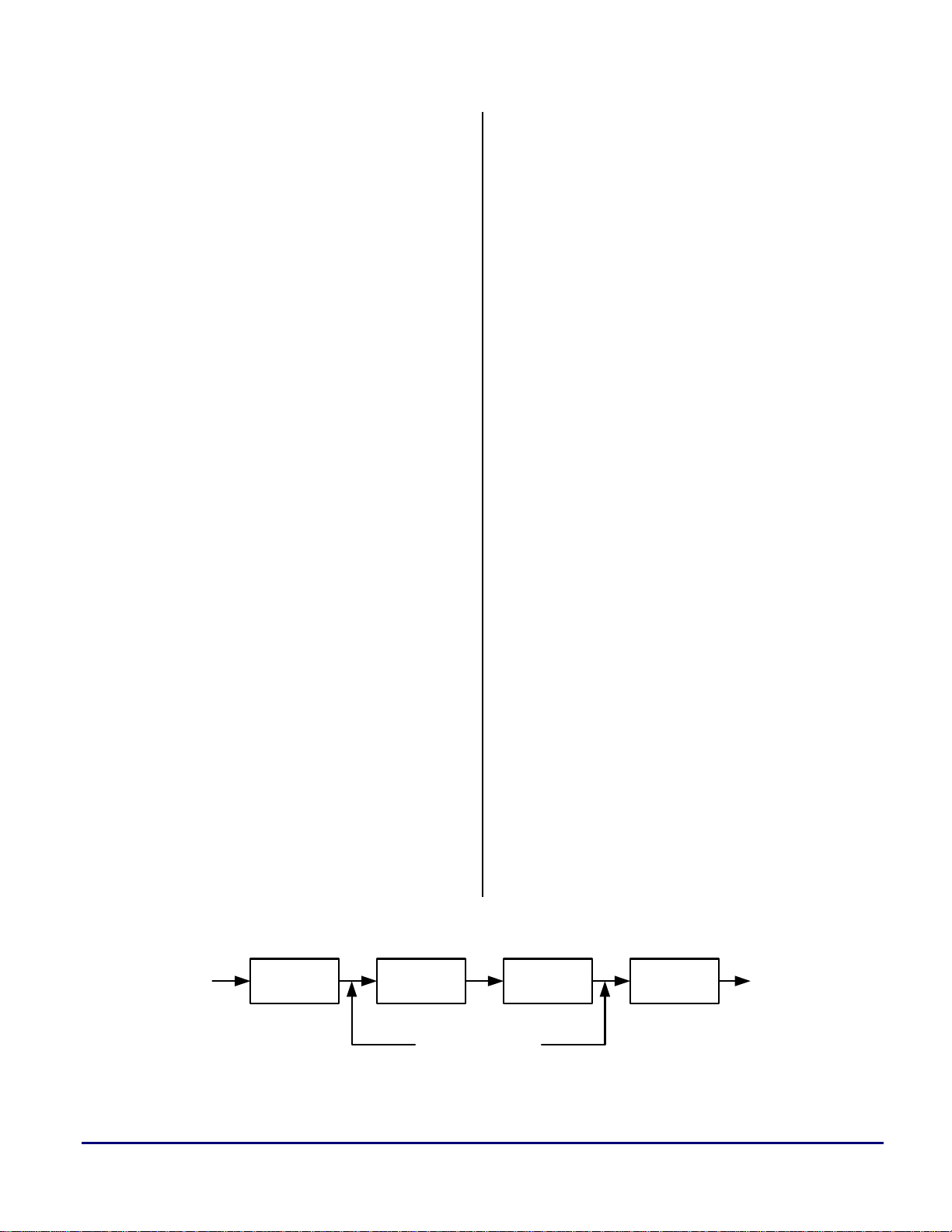
1.4 Sample Rate Conversion by Rational Factor L/M
To perform sample rate conversion by a rational factor
L/M, the incoming signal is first interpolated by a factor M.
The interpolation must be performed first to preserve the
spectral content of the signal. Graphically, this process can
be represented by the following diagram:
x(n)
Sampling rate
Fx
Figure 1. Block Diagram of a Rational SRC
Rational Sample Rate Conversion with Blackfin® Processors (EE-183) Page 2 of 26
Up Sampler
by L
Anti-imaging
lowpass filter
sample rate LFx
Anti-Aliasing
lowpass filter
Down
Sampler
by M
y(m)
Sampling rate
(L/M)Fx
Page 3
a
The anti-aliasing and anti-imaging lowpass filters can be
combined into a single low-pass filter.
1.5 Polyphase Filters
Polyphase filters are used to implement multirate filters.
The polyphase filters for interpolation-only and
decimation-only filters have a simpler structure than the
polyphase filter used between an interpolator and a
decimator.
1.5.1 Interpolator-Only Polyphase Filters
The computational efficiency of the Interpolator filter
structure can also be achieved by reducing the large FIR
filter of length K into a set of smaller filters. These smaller
filters will have a length N = K/L, where K is selected to
be a multiple of L. Since the interpolation process inserts L
- 1 zeros between successive values of x(n), only N out of
the K input values stored in the FIR filter at any one time
are nonzero. At one time instant, these nonzero values
coincide and are multiplied by the filter coefficients
h(0),h(L), h(2L),...,h(K - L). In the following instant, the
nonzero values of the input sequence coincide and are
multiplied by the filter coefficients h(1), h(L + 1), h(2L +
1),...h(K - L + 1), and so on. This observation leads us to
define a set of smaller filters called polyphase filters, with
unit sample responses:
pk (n)=h(k+nL) k = 0,1,...,L – 1
n = 0,1,...,N – 1 (5)
where N = K/L is an integer.
Additional insight can be gained about the characteristics
of the set of polyphase subfilters by noting that p
obtained from h(n) by decimation with a factor L.
Consequently, if the original filter frequency response
H(w) is flat over the range each of the polyphase subfilters
will possess a relatively flat response over the range (i.e.
the polyphase subfilters are basically allpass filters and
differ primarily in their phase characteristics). This
explains the reason for the term “polyphase” in describing
these filters. The polyphase filter can also be viewed as a
set of L subfilters connected to a common delay line.
Ideally, the kth subfilter will generate a forward time shift
of (k/L)F
subfilter. Therefore, if the zeroth filter generates zero
delay, the frequency response of the kth subfilter is:
pk(w) =e
in, for k = 0, 1 2,..., L - 1, relative to the zeroth
k
L
jw
(6)
(n) is
k
1.5.2 Decimator-Only Polyphase Filters
By transposing the interpolator structure we obtain a
commutator structure for a decimator that is based on the
parallel bank of polyphase filters. The unit sample
responses of the polyphase filter are now defined as:
pk(n) = h(k+nM) k = 0,1,...,M - 1
n = 0,1,...,N – 1 (7)
where N = K/M is an integer when K is selected to be a
multiple of M. The commutator rotates in a counterclockwise direction starting with filter p
1.5.3 Simultaneous Interpolator and Decimator
Polyphase Filter
A Polyphase filter which is used to perform lowpass
filtering between an interpolator and decimator function is
more complicated than the structures previously discussed
for either the Decimator-Only or Interpolator-Only phases.
In the Interpolator-Only case, one input leads to several
outputs, and in the Decimator-Only case, many inputs lead
to a single output. Thus, there is a relatively simple
relationship between the polyphase subfilters and h(n), the
lowpass filter coefficients. An interpolator of L samples
followed by a decimator of M samples means that L input
values must lead to M output values.
y(m) is the output of the polyphase filter
g(n,m) is the polyphase filter coefficients
h(n) is the lowpass filter used for both antiimaging of the interpolator and anti-aliasing of the
decimator
(n).
0
[x] denotes the largest integer in x (8)
mM
g(n,m) = h(nL +mM - [
]* l)
L
n=0,…,N-1 and m=0,…,L-1 (9)
y(m) =
−=10N
∑
n
g(n,m-[
M
] L) x([•
L
mM
L
]-n)
where K is the filter length of h(n) and L|K
with N = K/L, m=0,…,L-1 (10)
In a multistage implementation, this type of polyphase
filter is used between the interpolator and the decimator
stage. All other stages are either simple decimation or
Rational Sample Rate Conversion with Blackfin® Processors (EE-183) Page 3 of 26
Page 4

a
interpolation stages. The polyphase filters are exactly those
described in Section1.5.1 and Section1.5.2. An excellent
discussion of this topic is available in Chapter 10 of
Digital Signal Processing by Proakis and Manolakis.
1.6 Polyphase, Multistage Filter Design
Given an input sampling frequency F
output sampling frequency F
frequency F
of both F
is the Least Common Multiplier (or LCM)
min
and F
in
. The decimator of the sample rate
out
conversion is defined as D = F
is defined as U = F
/ F
min
(integer), then the smallest
out
min
. The number of primes in the
in
decimator is the maximum number of stages in the
decimation structure design. If the decimator is 24= 2 * 2 *
2 * 3, then the maximum number of stages is 4. Likewise,
the number of primes in the interpolator is the maximum
number of stages in the interpolation structure design. Thus
it is possible to have a different optimum multirate
structure for a multistage decimation structure as opposed
to a multistage interpolation structure.
If you choose M = D, L = U, then you are in a design of a
SRC system (U/D), but you can also choose M = RD, and
L = RU to get an equivalent system (RU/RM) for any
positive integer R. The user can choose R = 1, 2, 4,...
A design of a SRC requires the selection of a structure:
decimation or interpolation, over-sample rate R = 1, 2,
4,…, number of stages, a factor for each stage, and a
lowpass filter for each stage. The product of all the stage
factors should be equal to the decimator if a decimation
structure is selected or interpolator if an interpolation
structure is selected, times the over-sample rate R.
Momentum Data Systems (MDS) has developed a program
to create and optimize SRC structures and generate
coefficients: Advanced QED Series Sample Rate
Conversion System (Windows 95/NT Version only) Version
www.mds.com). This program has two methods for
2.2. (
best design of decimation and interpolation structures:
minimizing the sum of filter lengths, and minimizing the
number of computations of the signal filtering. The number
of computations is calculated as follows:
If U1, U2 and U3 are up-sample factors for a 3-stage
interpolation structure, and L1, L2 and L3 are the filter
lengths for 3-stages respectively, then the number of
computations is
L1 + L2 * U1 + L3 * U1 * U2, or equivalent L3/U3 +
L2/(U2*U3) + L1/(U1*U2*U3)
If D1, D2 and D3 are down-sample factors for a 3-stage
decimation structure, then the number of computations is
(integer) and an
in
/ F
and the interpolator
out
L3 + L2 * D3 + L1 * D3 * D2, or equivalent L1/D1 +
L2/(D1*D2) + L3/(D1*D2*D3)
This design problem is not a single-objective optimization
problem. The number of computations, the number of filter
taps and the complexity of the multi-structure enter in the
calculations. The problem becomes particularly
complicated if the number of stages is greater than 3.
This EE-Note used the QED Series Sample Rate
Conversion System to determine the optimum SRC
structures and all coefficients.
1.7 SRC Code Overview
The work described in this EE-Note was based on the
principles discussed in Section 1.1 through Section 1.6.
From this, a polyphase multistage SRC was implemented
on the ADSP-BF535 Blackfin® Processor.
A zip file (SRC.zip) containing the VisualDSP++™ 3.1
projects discussed here can be obtained from Analog
Devices (
imported into later versions of VisualDSP++. The Default
C Linker Description File (*.ldf) for the latest version of
VisualDSP++ should be used to recompile/relink these
projects. Make sure BUFIN is defined in the assembly
options (see Section 1.7.3). The SRC and main program C
shell (SRC.c) were developed using the ADSP-BF535 EZ-
KIT Lite™ Evaluation Platform. The C shell contains
function calls and routines to initialize the state of the
ADSP-BF535 as well as the SRC. Since this code does not
use any DMA capabilities or peripherals, this ‘core’ code
should port directly to next generation ADSP-BF5xx
Blackfin Processors. All code for this project is listed in
the Appendix.
The following were the design objectives used in
developing the SRC functions:
• The optimized assembly routines are to be C callable
• All input and output data should be 16 bits.
• All intermediate calculations should be 32-bit double-
• All filter coefficients should be 32-bit.
• All filters were designed for audio applications with
0.2dB passband ripple
58dB stopband ripple
• The MIPS budget should be ≤ 2 MIPS for all SRC
www.analog.com). These files can be easily
(See src_init.asm and src_flt.asm in the Appendix).
precision (maintaining 31.5 bits of precision per MAC).
these criteria:
examples.
Rational Sample Rate Conversion with Blackfin® Processors (EE-183) Page 4 of 26
Page 5
The program assumes input data comes from a 16-bit
buffer (initialized as ‘x’ in the shell). This data is copied
into a 32-bit buffer ‘in1’ within src_flt.asm. At the end of
src_flt.asm, the last 32-bit buffer ‘inx’ (where ‘x’ is the last
stage) is copied into a 16-bit buffer (‘y’ in the shell). These
16-bit input/output buffers can be eliminated to conserve
data space. In this case, you will need to undefine
‘BUFIN’ and preload 'in1' with 32-bit data and then use
the 32-bit output data from ‘inx’.
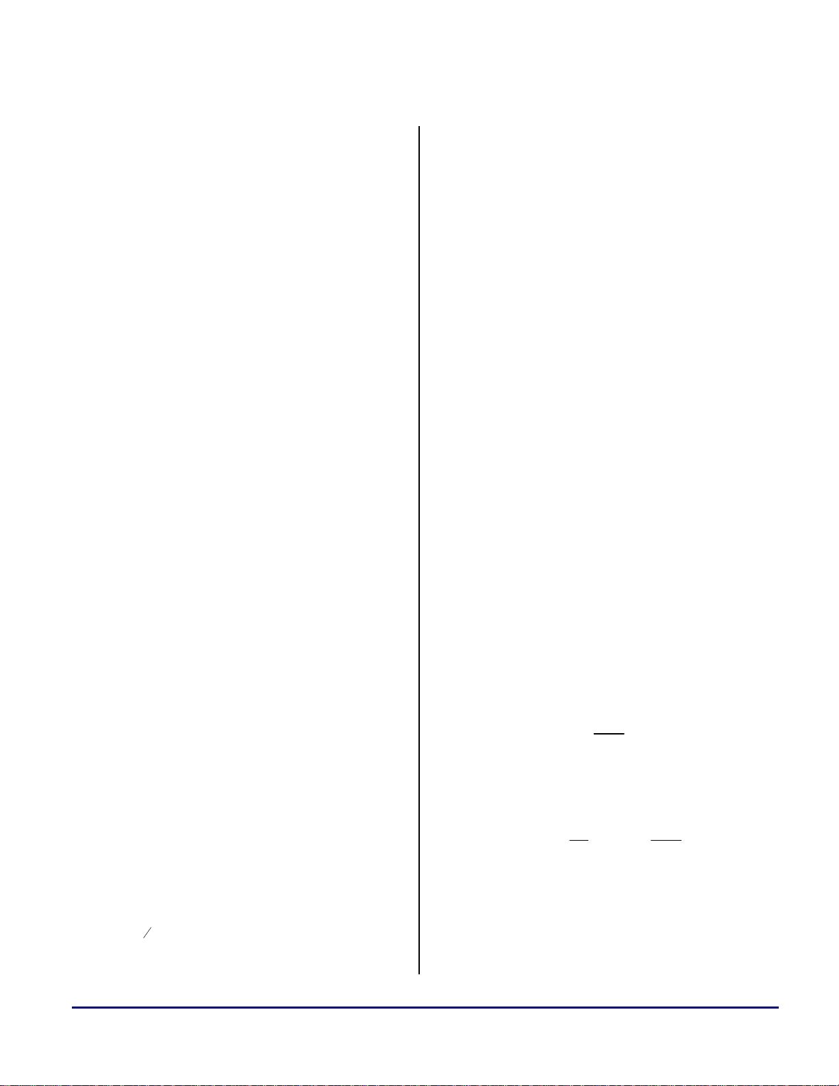
The filters were designed to convert between selected
standard audio sample rates (Hz): 48000, 44100, 32000,
22050, 16000, 11025, and 8000. See Figure 1 for the audio
SRC matrix. Note that an ‘x’ in the matrix denotes that the
SRC filter was designed and is included in SRC.zip. If you
have the SRC program from MDS (or similar) you can
generate coefficients for any SRC. See Section 1.7.2
below.
Figure 3. ‘x’ Input Data for 44.1KHz sampling of a
250Hz sine wave.
a
Figure 2. Audio SRC Matrix
The #2 workspace in this project has all the necessary plots
of the input/output stages as well as the intermediate
buffers. You can look at the data in the time domain or
apply the VisualDSP++ built-in FFT plotting function to
analyze the frequency domain. Load
‘plots_xxxxtoxxxx.vdw’ for a particular SRC.
A ‘SINE_xxxxx_16bit_1024.dat’ input file was generated
to test every SRC. This is a 16-bit, 1024-sample, 1KHz or
250Hz sine wave at the input sample rate. These input files
were generated using MATLAB® scripts (see
‘gen_sine_wave_comma_16.m’). It's easy to verify proper
SRC functionality by counting samples in one period at
both the input rate (in the ‘x’ plot) and the output rate (in
the ‘y’ plot) in workspace #2. See Figure 2 and Figure 3.
Figure 4. 'y' Output Data for 48KHz SRC of a
250Hz sine wave
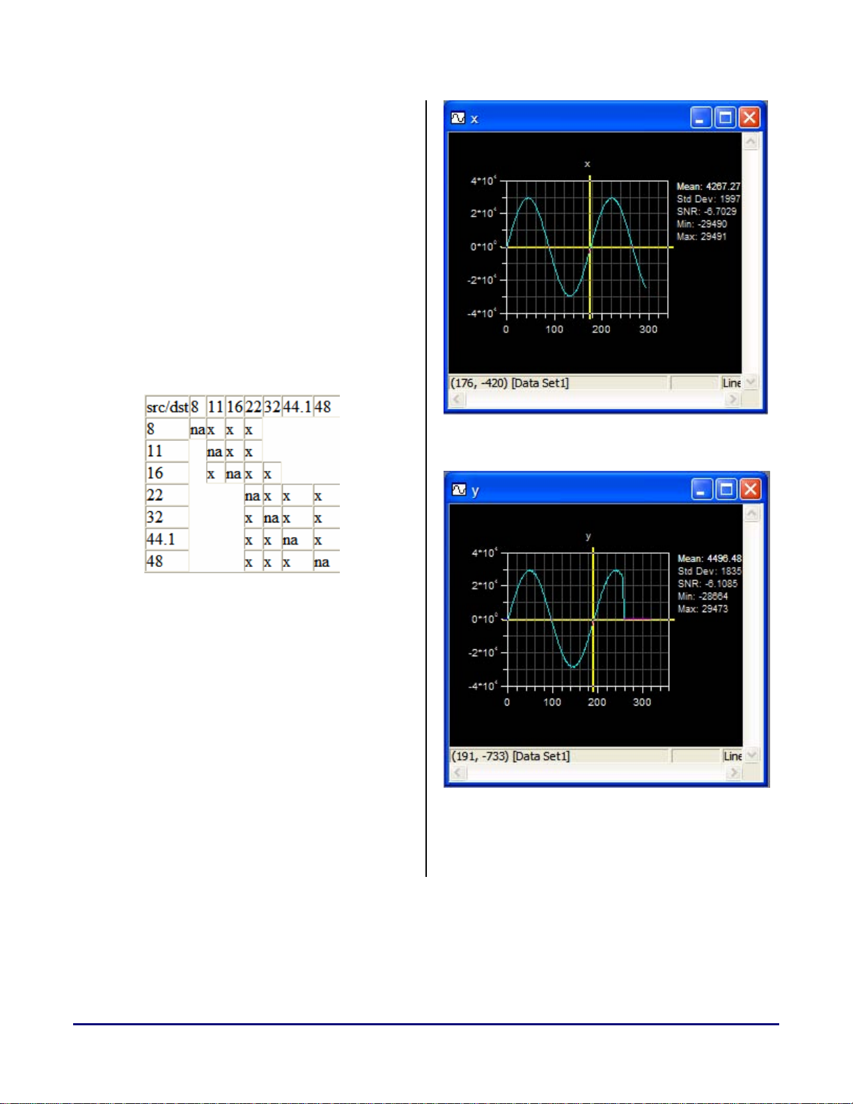
The built-in FFT plotting functions were also used to
analyze input and output data. See Figure 4 and Figure 5.
Rational Sample Rate Conversion with Blackfin® Processors (EE-183) Page 5 of 26
Page 6
Figure 5. FFT of 'x' Input Data at 250Hz
Figure 6. FFT of 'y' Output Data at 250Hz
1.7.1 Input/Output Data Sizes and the GCD
The size of NINPS and NOUTS can be modified in each
‘src_xxxxtoxxxx.h’ file (see example of src_441to48.h in
the Appendix). This will allow the user to vary the size of
the input/output buffers according to system block
processing needs. It was envisioned that the end
application would be operating on blocks of audio samples.
Note that the smallest block size can be no less than the
LCM discussed in Section 1.6. However, an integer
multiple of the LCM can be applied to increase the
a
processed block size. The user can increase or decrease the
integer multiple of the LCM (or Greatest Common
Denominator, GCD, in Table 2) by changing the buffer
sizes NINPS and NOUTS. These two numbers must be at
least half of the greatest filter coefficient count times the
INTPx to ensure valid output data. Table 1 was generated
from a simple C program:
GCD=48000, Original=48000/48000, NEW=1/1
GCD=300, Original=48000/44100, NEW=160/147
GCD=16000, Original=48000/32000, NEW=3/2
GCD=150, Original=48000/22050, NEW=320/147
GCD=16000, Original=48000/16000, NEW=3/1
GCD=75, Original=48000/11025, NEW=640/147
GCD=8000, Original=48000/8000, NEW=6/1
GCD=300, Original=44100/48000, NEW=147/160
GCD=44100, Original=44100/44100, NEW=1/1
GCD=100, Original=44100/32000, NEW=441/320
GCD=22050, Original=44100/22050, NEW=2/1
GCD=100, Original=44100/16000, NEW=441/160
GCD=11025, Original=44100/11025, NEW=4/1
GCD=100, Original=44100/8000, NEW=441/80
GCD=16000, Original=32000/48000, NEW=2/3
GCD=100, Original=32000/44100, NEW=320/441
GCD=32000, Original=32000/32000, NEW=1/1
GCD=50, Original=32000/22050, NEW=640/441
GCD=16000, Original=32000/16000, NEW=2/1
GCD=25, Original=32000/11025, NEW=1280/441
GCD=8000, Original=32000/8000, NEW=4/1
GCD=150, Original=22050/48000, NEW=147/320
GCD=22050, Original=22050/44100, NEW=1/2
GCD=50, Original=22050/32000, NEW=441/640
GCD=22050, Original=22050/22050, NEW=1/1
GCD=50, Original=22050/16000, NEW=441/320
GCD=11025, Original=22050/11025, NEW=2/1
GCD=50, Original=22050/8000, NEW=441/160
GCD=16000, Original=16000/48000, NEW=1/3
GCD=100, Original=16000/44100, NEW=160/441
GCD=16000, Original=16000/32000, NEW=1/2
GCD=50, Original=16000/22050, NEW=320/441
GCD=16000, Original=16000/16000, NEW=1/1
GCD=25, Original=16000/11025, NEW=640/441
GCD=8000, Original=16000/8000, NEW=2/1
GCD=75, Original=11025/48000, NEW=147/640
GCD=11025, Original=11025/44100, NEW=1/4
GCD=25, Original=11025/32000, NEW=441/1280
GCD=11025, Original=11025/22050, NEW=1/2
GCD=25, Original=11025/16000, NEW=441/640
GCD=11025, Original=11025/11025, NEW=1/1
GCD=25, Original=11025/8000, NEW=441/320
GCD=8000, Original=8000/48000, NEW=1/6
GCD=100, Original=8000/44100, NEW=80/441
GCD=8000, Original=8000/32000, NEW=1/4
GCD=50, Original=8000/22050, NEW=160/441
GCD=8000, Original=8000/16000, NEW=1/2
GCD=25, Original=8000/11025, NEW=320/441
GCD=8000, Original=8000/8000, NEW=1/1
Table 1. Greatest Common Denominator for Audio SRC
Rational Sample Rate Conversion with Blackfin® Processors (EE-183) Page 6 of 26
Page 7

a
1.7.2 Coefficient Generation and Formatting
Assuming a program that is similar to the MDS tool is
used, some data formatting must be performed. The
following must be done to convert the raw decimal filter
coefficients. With MDS, a *.dsp file is produced. Table 2
is an example of the MDS data format for the *.dsp file.
This file must be properly formatted as a 32-bit
hexadecimal VisualDSP++ input data file (*.dat). This is
then read (by VisualDSP++) into the corresponding
variable at initialization:
a. Use Microsoft Excel to import the *.dsp file (space
delimited). Select the "D" column and erase everything
but the decimal filter coefficients. Save the file as a
‘Formatted Text (Space Delimited)(*.prn)’ file.
/* External References */
.external src_init;
.external src_flt;
#define STAGE 3 /* Number of stages */
#define INTP0 160 /* Interpolation factor */
#define DOWN0 147 /* Decimation factor */
/* ------------------------------------------------------------ */
/* parameters for each stage */
#define INTP1 2
#define DOWN1 1
#define LENG1 223
#define PLEN1 112
#define MLEN1 224
#define SHFT1 0
#define NINP1 147
#define SZIN1 512
#define INTP2 5
#define DOWN 2 1
#define LENG2 27
#define PLEN2 6
#define MLEN2 30
#define SHFT2 0
#define NINP2 94
#define SZIN2 512
#define INTP3 16
#define DOWN3 147
#define LENG3 49
#define PLEN3 4
#define MLEN3 64
#define SHFT3 0
#define NINP3 1470
#define SZIN3 2048
#define NINP4 160
#define SZIN4 256
/* ------------------------------------------------------------------------ */
.VAR/DM flt1[MLEN1];
.INIT flt1:
0xffc8, /* -1.72471041e-003 cf 000 pp 000 ft 1 */
0xfffe, /* -8.01035724e-005 cf 002 pp 000 ft 1 */
0x000f, /* 4.65568547e-004 cf 004 pp 000 ft 1 */
0xfffa, /* -2.00361260e-004 cf 006 pp 000 ft 1 */
0x000c, /* 3.90279025e-004 cf 008 pp 000 ft 1 */
0xfff2, /* -4.43292360e-004 cf 010 pp 000 ft 1 */
0x0013, /* 6.04802800e-004 cf 012 pp 000 ft 1 */
0xffe8, /* -7.54936936e-004 cf 014 pp 000 ft 1 */
0x001e, /* 9.43581218e-004 cf 016 pp 000 ft 1 */
., . . .
., . . .
., . . .
Listing 1. Coefficient Format from MDS
b. Use the included MATLAB® script ‘dec_file_to_hex_file_converter.m’. This script will read in decimal
(exponential) data from the *.prn file and convert to a
32-bit Hexadecimal format (*.dat file) suitable to be read
by VisualDSP++ within a data initialization section. This
MATLAB® script can be easily modified for other
formats.
1.7.3 BUFIN Define
When ‘BUFIN’ is undefined (under VisualDSP++:
PROJECT OPTIONS / ASSEMBLER / ADDITIONAL
OPTIONS: ‘-D BUFIN’), the SRC program assumes that
buffer ‘in1’ is preloaded with 32-bit input data AFTER the
src_init is accomplished (buffer zeroing). This requires that
the shell program preload ‘in1’ from a 32-bit source.
Define ‘BUFIN’ to include the 16-bit buffer transfer code
within src_flt.asm. ‘x’ and ‘y’ 16-bit input buffers are not
necessary for a final application but they do allow for
easier data manipulation for test purposes.
1.7.4 Zeroing Filter Delays
To "zero" out filter delays, use the following equations as
offsets to first valid output data:
1st Offset = (LENG1-1)/(2*DOWN1)
2nd Offset = INTP2/DOWN2*1st Offset + (LENG2-1)/(2*DOWN2)
3rd Offset = INTP3/DOWN3*2nd Offset + (LENG3-1)/(2*DOWN3)
See the constants generated in the 'src_xxxxtoxxxx.h’ files.
DOFSx is actually the offset from the end of the buffer.
Therefore it is the number of valid output data samples.
This will determine how often this routine needs to be
executed in a block processed system. Be careful with this
number. The preprocessor in VisualDSP++ will not
generate fractional constants. Therefore, depending on the
math here, DOFSx could have an error of ±1 sample. For a
particular SRC, check the first sample in ‘y’ and adjust the
DOFSx accordingly.
Rational Sample Rate Conversion with Blackfin® Processors (EE-183) Page 7 of 26
Page 8

a
1.7.5 Reducing Intermediate Buffers
One idea to reduce the number of intermediate buffers is to
implement a ‘zero_buf’ function (not included) that would
re-zero the buffers between filter sections. This would
reduce the number of intermediate buffers to two at the
expense of more MIPS to accomplish the SRC. However,
the MIPS increase would be negligible and is on the order
of the size of the buffer times the number of times it is
zeroed. These two intermediate buffers should be sized to
the maximum needed for any SRC.
1.7.6 Restrictions
If there is a large interpolation constant INTPx, this
severely reduces the number of valid data samples in the
final output buffer. For example, in the 44.1K to 48K SRC,
there is an interpolation constant of 16 in the 3rd stage. If
we only use L1 data sections (max = 4096 bytes) we only
get 111 valid data samples in the final output buffer.
However, if we can use L2 (like what is available in the
ADSP-BF535) and make this intermediate buffer as large
as 4096 words (16K bytes), we can get a relatively large
number of valid output data samples. Depending on
interpolation constants and the need to run out of single
cycle L1 memory, the limiting factor appears to be the L1
section size. We can maximize all the filters based on this
L1 section size (4096 bytes or 1024 32-bit words) or
assume we can use L2 (internal or external) and make the
intermediate buffers larger. In the latter case, the number
of valid output data samples greatly increases.
1.7.7 Unresolved Issues
The following SRCs produced corrupted output data when
using a 3-stage interpolator structure:
passband ripple = 0.0001 and a stopband ripple = 98dB.
This provided a overall SNR of 90dB through all 3 stages
of the filter. This was tested using Cooledit 2000 software.
If a lesser system SNR is desirable (50-70dB), a 32-bit
implementation will provide a SNR that is close to the
stopband attenuation. For higher system SNR's (above
90dB), much higher stopband attenuations are required.
Conclusions
The code and filters in this EE-Note were generated
specifically with audio SRC in mind. Notwithstanding, by
generating new filter input files with tighter passband and
stopband ripple, this code could be used unaltered for
many different applications. Keep in mind that we gained
computational efficiency by eliminating the LxL multiply
and thus only retaining 31.5 bits of precision for each
Multiply And Accumulate (MAC). This amount of
precision is more than enough for most applications.
Notice in src_flt.asm that the inner MAC loops are only 2
cycles, enabling double precision math with very little
overhead. This “low cycle” double precision capability of
Blackfin™ is one of the great advantages of this
architecture over competing single MAC architectures.
Placement of data and code sections (i.e. L1, internal or
external L2) is up to the user. However, coefficients and
data should be placed in separate banks to avoid stalls
(only applies to L1). Also, whether cache or SRAM is used
will greatly impact the overall cycle counts. Since there are
many filters required for all the various audio SRC
combinations, it was assumed that coefficients would be
placed in a larger external L2 SRAM or SDRAM. These
coefficients could either be cached internally or brought
into L1/L2 via DMA concurrent to block processing.
11025to16,
16to2204, and
8to11025
Therefore, a 2-stage filter decimator structure was used
instead and produced valid results. It appears that the MDS
filter generator produced corrupted 3rd stage outputs for all
SRCs that up-converted between two similar rates. The
MDS program chose by default a 3-stage interpolator
structure in each of these cases.
1.7.8 Case Study of Total SNR
Two common SRC changes are 44.1KHz to 48KHz and
48KHz to 44.1KHz. Instead of using the stopband and
passband ripples above, a filter was generated with
Rational Sample Rate Conversion with Blackfin® Processors (EE-183) Page 8 of 26
Recommendations for Further Development
The code developed in this EE-Note can be applied to any
application requiring SRC. For example, many video
applications require the ability to scale images to change
the video size (D1 to CIF, etc.). This Polyphase multistage
SRC approach could be modified to work on byte-wide
single precision video data. The basic structure of this code
would not require many alterations. Instead of working on
one time-domain double-precision data sample per cycle,
the SRC would be modified to operate on two byte-wide
frequency-domain data samples per cycle.
Finally, the code has not been completely optimized.
Improvements can be made to reduce overall cycles
particularly the elimination of pipeline stalls.
Page 9

a
Appendix
SRC.c
/****************************************************************************
* File: SRC.c
* Date Started: Sept 26 2002
* Created: Jeff Sondermeyer
****************************************************************************/
/*
(C) Copyright 2002 - Analog Devices, Inc. All rights reserved.
File Name: SRC.c
Date Modified: 3/12/2004 Jeff Sondermeyer Rev 0.3
Purpose: The Sample Rate Converter (SRC) and Main Program Shell Developed using the ADSP-21535 EZ-KIT
Lite Evaluation Platform. This C shell contains function calls and routines to initialize the state of
the 21535 as well as the SRC. This program assumes input data comes from a 16-bit buffer (initialized
as 'x' in this shell). This data is copied into a 32-bit buffer 'in1' within src_flt.asm. At the end
of src_flt.asm, the last 32-bit buffer 'inx' (where 'x' is the last stage) is copied into a 16-bit
buffer ('y' in this shell). These 16-bit input/output buffers can be eliminated to conserve data
space. In this case, you will need to undefine 'BUFIN' and preload 'in1' with 32-bit data and then
use the 32-bit output data from 'inx'. The converter was designed to convert between any of the
following rates: 48000, 44100, 32000, 22050, 16000, 11025, and 8000. If you have the SRC program from
Momentum Data Systems you can generate coefficients for any SRC. Follow #3 below. The #2 workspace in
this project has all the necessary plots of the input/output stages as well in the intermediate
buffers. You can look at the data in the time domain or apply the built-in FFT plotting function to
analyze the frequency domain. Load "plots_xxxxtoxxxx.vdw" for a particular SRC. I have generated a
"SINE_xxxxx_16bit_1024.dat" input file to test every SRC. This is a 16-bit, 1024-sample, 1KHz sine
wave at the input sample rate. These were generated using MATLAB (see 'gen_sine_wave_comma_16.m').
It's easy to verify proper conversion by counting samples in one period at both the input rate (in the
'x' plot) and the output rate (in the 'y' plot) in workspace #2.
Notes:
1. You can modify the size of NINPS and NOUTS in each 'src_xxxxtoxxxx.h' file. However, it MUST be
the same multiple of the GCD.
2. Buffer sizes, NINPS and NOUTS must be at least half of the filter coefficient sizes times the INTPx
value to ensure valid output data.
3. Do the following to convert the decimal filter coefficients from Momentum Data Systems SRC *.dsp
file to properly format this data as 32-bit Hexidecimal value. This is then read into the
corresponding variable at initialization:
a. Use Excel to import the *.dsp file (space delimited). Select the "D" column and erase everything
else. Save the file as a "Formatted Text (Space Delimited)(*.prn)" file.
b. Use the MATLATB program "dec_file_to_hex_file_converter.m". This MATLAB program will read in
decimal (exponential) data from a file (*.prn) and convert to a 32-bit Hexidecimal format (*.dat file)
suitable to be read by VisualDSP within a data initialization section.
4. When 'BUFIN' is undefined, the program assumes that 'in1' is preloaded with 32-bit input data AFTER
the src_init is accomplished (buffer zeroing). This requires that the shell program preload 'in1'
from a 32-bit source. Define 'BUFIN' to include the 16-bit buffer transfer code within src_flt.asm.
x and y 16-bit buffers are nice but is just another chunk of memory that is necessary.
5. To "zero" out filter delays, use the following equations as offsets to first valid data:
1st Offset = (LENG1-1)/(2*DOWN1)
2nd Offset = INTP2/DOWN2*1st Offset + (LENG2-1)/(2*DOWN2)
3rd Offset = INTP3/DOWN3*2nd Offset + (LENG3-1)/(2*DOWN3)
See the constants generated in the 'src_xxxxtoxxxx.h' files.
6. DOFSx (in src_xxxxtoxxxx.h) is the offset and also is the number of valid output data samples.
This will allow you to figure how often this routine needs to be executed in a block-processed system.
Be careful with this number. The preprocessor in VDSP will not generate fractional constants.
Therefore, depending on the math here, DOFSx could have an error of +/-1. For a particular SRC, check
the first sample in 'y' and adjust the DOFSx accordingly.
7. One idea of reducing the number of intermediate buffers is to call a 'zero_buf' function that would
rezero the buffers between filter sections. This would reduce the number of intermediate buffers to
two at the expense of more MIPs. However, the MIPs increase would be negligable and is on the order
of the size of the buffer. These two intermediate buffers should be sized to the maximum needed for
any SRC.
8. If there is a big interpolation constant, this severely reduces the number of valid data samples in
the final output buffer. For example, in the 44.1K to 48K case, there is an interpolation constant of
16 in the 3rd stage. If we only use L1 data sections (max = 4096 bytes) we only get 111 valid data
samples in the final output buffer. However, if I use L2 and make this intermediate buffer as large as
Rational Sample Rate Conversion with Blackfin® Processors (EE-183) Page 9 of 26
Page 10

4096 words (16K bytes), I can get a relatively large number of valid output data samples. The point
here is that.. depending on interpolation constants, the limiting factor appears to be the L1 section
size. I can maximize all my filters based on this L1 section size (4096 bytes or 1024 words) ...OR..
assume someone can use L2 and make the intermediate buffers larger. In the later case, the number of
VALID output data samples greatly increases.
9. The half band code was not implemented. Therefore, the HALFB define is not used.
10. 11025to16, 16to2204, and 8to11025 produced corrupted data with 3-stage filters. Had to use 2stages. MDS filter generator produces corrupted 3rd stage output for close sample rate conversions
that required up sampling??? Not sure why.
11. The latest revision of the code was debugged on a Momentum Systems Hawk PCI board. All FileIO was
done over the PCI bus. Several things need to change in this code to work with the Hawk board:
a. Define ‘HAWK’
b. Add idle.c and the basiccrt.s file for the Hawk board to the project.
*/
/* ------------------------------------------------------------------------ */
#include "fract_math.h"
#include <defBF535.h>
#include "src_inc.h"
#include "src_441to48.h"
#include <stdlib.h>
#include <stdio.h>
//#include <device.h>
/* ------------------------------------------------------------------------ */
// 16-bit input/output buffers
static segment("L1_data_b")
short x[NINPS];
static segment("L1_data_b")
short y[NOUTS];
FILE *inFile,*outFile;
// 32-bit intermediate buffers
segment("L1_data_a")
int in1[SZIN1];
segment("L1_data_a")
int in2[SZIN2];
#if STAGE>=2
segment("L1_data_a")
int in3[SZIN3];
#endif
#if STAGE==3
segment("L1_data_a")
int in4[SZIN4];
#endif
// Filter Coefficients
static segment("L1_data_b")
int filter_h1[MLEN1] =
{
#include "441to48_32bit_flt1.dat"
};
#if STAGE>=2
static segment("L1_data_b")
int filter_h2[MLEN2] =
{
a
Rational Sample Rate Conversion with Blackfin® Processors (EE-183) Page 10 of 26
Page 11

#include "441to48_32bit_flt2.dat"
};
#endif
#if STAGE==3
static segment("L1_data_b")
int filter_h3[MLEN3] =
{
#include "441to48_32bit_flt3.dat"
};
#endif
///////////////////////////////////////////////////////////////////
// This line enables the PCI as the default device for file I/O
//#pragma retain_name
//extern int __default_io_device = PCI_IO;
//extern int __default_io_device = FILEIO;
///////////////////////////////////////////////////////////////////
/* ------------------------------------------------------------------------ */
static void init_first_stage(STAGE_HANDLE *S) {
FIRST_STAGE_ENTRY *V;
V = S->V;
V->in_s = &in1[0];
V->in_z = SZIN1;
V->out_s = &in2[0];
V->out_z = SZIN2;
V->h = &filter_h1[0];
V->plen = PLEN1-1;
V->up = INTP1;
V->dn = DOWN1;
V->nis = NINP1;
V->nos = NINP2;
V->nshft = SHFT1;
V->in_c = &in1[0];
V->out_c = &in2[0];
}
#if STAGE>=2
static void init_sec_stage(STAGE_HANDLE *S) {
SEC_STAGE_ENTRY *M;
M = S->M;
M->in_s = &in2[0];
M->in_z = SZIN2;
M->out_s = &in3[0];
M->out_z = SZIN3;
M->h = &filter_h2[0];
M->plen = PLEN2-1;
M->up = INTP2;
M->dn = DOWN2;
M->nis = NINP2;
M->nos = NINP3;
M->nshft = SHFT2;
M->in_c = &in2[0];
M->out_c = &in3[0];
}
#endif
#if STAGE==3
static void init_last_stage(STAGE_HANDLE *S) {
THIRD_STAGE_ENTRY *L;
L = S->L;
L->in_s = &in3[0];
L->in_z = SZIN3;
a
Rational Sample Rate Conversion with Blackfin® Processors (EE-183) Page 11 of 26
Page 12

L->out_s = &in4[0];
L->out_z = SZIN4;
L->h = &filter_h3[0];
L->plen = PLEN3-1;
L->up = INTP3;
L->dn = DOWN3;
L->nis = NINP3;
L->nos = NINP4;
L->nshft = SHFT3;
L->in_c = &in3[0];
L->out_c = &in4[0];
}
#endif
/* ------------------------------------------------------------------------ */
static segment("L1_data_b")
FIRST_STAGE_ENTRY vst;
static segment("L1_data_b")
SEC_STAGE_ENTRY mst;
static segment("L1_data_b")
THIRD_STAGE_ENTRY lst;
static segment("L1_data_b")
STAGE_HANDLE sth;
static segment("L1_data_b")
FUNDAMENT_DATA_ENTRY vfd;
/* ------------------------------------------------------------------------ */
void init_stage_handle (void) {
STAGE_HANDLE *S;
S = &sth;
S->V = &vst;
#if STAGE>=2
S->M = &mst;
#endif
#if STAGE==3
S->L = &lst;
#endif
init_first_stage (S);
#if STAGE>=2
init_sec_stage (S);
#endif
#if STAGE==3
init_last_stage (S);
#endif
}
/* ------------------------------------------------------------------------ */
void init_src (void) {
FUNDAMENT_DATA_ENTRY *F;
F = &vfd;
F->S = &sth;
F->half_band = HALFB;
F->up_stage = NUPST;
F->pivot_stage = PVTFL;
F->down_stage = NDWNS;
F->nstages = STAGE;
F->ninputs = NINPS;
F->noutputs = NOUTS;
src_init (F);
}
a
Rational Sample Rate Conversion with Blackfin® Processors (EE-183) Page 12 of 26
Page 13

/* ------------------------------------------------------------------------ */
/*
Shell test program.. eventually I will use Fread and Fwrite to input/output ASCII files
(JWS)
*/
int i,j=0,count,file_status;
int getInput(short *inBuf,int count);
int writeOutput(short *outBuf,int count);
int main()
{
//int i,j=0,count,file_status;
/* initialize filter */
inFile = fopen("C:\\DSP\\sin_1khz_44khz.dat","rb");
outFile = fopen("C:\\DSP\\out_1khz_44to48.dat","wb");
init_stage_handle();
init_src();
count = getInput(x,NINPS);
while(count==NINPS)
{
/* filter samples */
j=j+1;
#if STAGE==3
src_flt (x, y, DOFS3, &vfd);
#endif
#if STAGE==1
src_flt (x, y, DOFS1, &vfd);
#endif
#if STAGE==2
src_flt (x, y, DOFS2, &vfd);
#endif
count = writeOutput(y,NOUTS);
count = getInput(x,NINPS);
}
fclose(inFile);
fclose(outFile);
}
int getInput(short *inBuf,int count)
{
int wordsRead=0;
wordsRead = fread(inBuf,sizeof(short),count,inFile);
return wordsRead;
}
int writeOutput(short *outBuf,int count)
{
a
Rational Sample Rate Conversion with Blackfin® Processors (EE-183) Page 13 of 26
Page 14

int wordsRead=0;
wordsRead = fwrite(outBuf,sizeof(short),count,outFile);
return wordsRead;
}
Listing 2. SRC.c
a
Rational Sample Rate Conversion with Blackfin® Processors (EE-183) Page 14 of 26
Page 15

Src_flt.asm
/* File: src_flt.asm Version 0.1
fundemental structure order:
1. stage data handle
2. half band flag (0,1, or 2)
3. number of up stages
4. pivot flag (0 or 1)
5. number of down stages
6. number of stages (total)
7. number of input samples per block
8. number of output samples per block
P0 -> fundamental structure
P1 -> input samples
P2 -> output samples
P3 -> memory storage and retreival
P4 = temporary pointer
P5 = loop counter
R0 = Loop counters
R1 = temporary storage
R2 = Loop counters
R3 = Shift count
R4 = inner loop calculations
R5 = inner loop calculations
R6 = temporary storage
R7 = temporary storage
I0 = dedicated to input buffer 'inx'
I1 = general use...reading 'inputData' plus others
I2 = general use...reading 'inx' for output data
I3 = general use...
Input Data Structure (VAR_SIZE words)
AIS: address of input signal (circular), updated after return,
SIS: circular size of AIS,
AOS: address of output signal (circular), updated after return,
SOS: circular size of AOS,
AFA: address of filter array,
LEN: poly-phase filter length,
UPR: up sample rate >= 2,
DNR: down sample rate = 1 is assumed
NIS: number of input signals
NOS: number of output signals
SHF: number of shift counter, 0 or 1
*/
.SECTION L1_data_a;
.align 4;
.byte4 pt_fundst; // pointer to fundamental structure
.byte4 pt2_fundst; // pointer to fundamental structure
.byte4 st_handle; // pointer to stage data handle
.byte2 inputs; // number of inputs
.byte2 outputs; // number of outputs
.byte2 diff_offset; // Offset difference
.GLOBAL _src_flt;
.SECTION program;
_src_flt:
a
Rational Sample Rate Conversion with Blackfin® Processors (EE-183) Page 15 of 26
Page 16

[--SP]=(R7:4,P5:3); // Push R7...
P1 = R0; // Address of input data
P2 = R1; // Address of output data
P0 = [SP+40]; // Address of fundemental structure
p3.l = diff_offset;
p3.h = diff_offset;
w[p3] = r2; // save DOFS3 (difference offset to strip filter delay off of
final buffer
p3.l = pt_fundst; // p3 -> to fundemental structure
p3.h = pt_fundst;
[p3] = p0; // save fundemental stage pointer in memory pointed at by p3
#ifdef BUFIN
p5 = 24; // 6*4 = 24 bytes (post increment points to number input samples
per block)
r6 = [p0++p5];
p4 = r6; // p4 -> stage handle
r6 = [p0++]; // r6 = number of inputs samples per block
p3.l = inputs; // p3 -> to number of input samples per block
p3.h = inputs;
w[p3] = r6; // save number of input samples per block
r6 = [p0++]; // r6 = number of output samples per block
p3.l = outputs; // p3 -> to number of output samples per block
p3.h = outputs;
w[p3] = r6; // save number of output samples per block
p0 = [p4++]; // p0 -> fist data structure
/******** IPDC comment *******/
// r6 = [p0++]; // r6 -> first input buffer 'inx'
// i0 = r6; // i0 -> first input buffer 'inx'
// b0 = r6; // b0 -> base of first input circular buffer
/******************************/
/*********IPDC addition*******/
p5 = 44;
r6 = [p0++p5]; // r6 -> first input buffer 'inx'
i0 = r6; // i0 -> first input buffer 'inx'
p5=-40;
r6 = [p0++p5];
b0 = r6; // b0 -> base of first input circular buffer
/******************************/
r6 = [p0++];
r6 = r6 << 2; // double length (4 bytes per word)
l0 = r6; // l0 = first input circular buffer size 'SZINx'
go_back:
// p3.l = num_blocks;
// p3.h = num_blocks;
// r6 = w[p3]; // get number of blocks
// r6 += -1; // Decrement number of blocks
// w[p3] = r6; // save decremented number of blocks
// CC = r6 < 0;
// IF CC JUMP RETURN_TO_SENDER; // Return if less than 1 block
p3.l = inputs; // p3 -> to number of input samples per block
p3.h = inputs;
r7 = w[p3];
p5 = r7; // p5 = number of input samples per block
i1 = p1; // load i1 with address of 'inputData'
l1 = 0;
LSETUP(READ_INPUTS_BEGIN, READ_INPUTS_END) LC0 = p5;
READ_INPUTS_BEGIN:
r6.h = w[i1++]; // read the input buffer 'inputData'
r6.l = 0;
a
Rational Sample Rate Conversion with Blackfin® Processors (EE-183) Page 16 of 26
Page 17

READ_INPUTS_END:
[i0++] = r6; // write input into input buffer 'inx'
// p1 = i1; // save i1 into p1
p3.l = pt_fundst; // p3 -> to fundemental structure
p3.h = pt_fundst;
r7 = [p3];
p0 = r7; // p0 -> to fundemental structure
#endif
src_core:
r7 = [p0++];
p3.l = st_handle;
p3.h = st_handle;
[p3] = r7; // store stage data handle
r6 = [p0++]; // r6 = half band flag (move past this for now)
r2 = [p0++]; // r2 = # of up stages
p3.l = pt2_fundst;
p3.h = pt2_fundst;
[p3] = p0; // save pointer to current fundemental structure
CC = r2 <= 0;
IF CC JUMP over_upstage; // if upstage = 0, jump over
UPSTAGE_BEGIN:
p3.l = st_handle;
p3.h = st_handle;
p4 = [p3]; // p4 -> current stage data handle
r7 = [p4++];
p0 = r7; // p0 -> stage data
[p3] = p4; // save pointer to stage data handle
up_src:
/******** IPDC comment *******/
// r7 = [p0++]; // r7 -> input signal 'inx'
// b3 = r7; // b3 set for circular buffering
/******************************/
/*********IPDC addition*******/
p4 = 44;
r7 = [p0++p4]; // r7 -> input signal 'inx'
p4 = -40;
r5 = [p0++p4];
b3 = r5; // b3 set for circular buffering
/******************************/
r5 = [p0++];
r5 = r5 << 2; // double the length (4 bytes per word)
l3 = r5; // l3 = Size of Input Stage (SIS)
/******** IPDC comment *******/
// r6 = [p0++];
// i2 = r6; // i2 -> output signal 'inx'+1 buffer (output buffer)
// b2 = r6; // b2 set for circular buffering
/******************************/
/*********IPDC addition*******/
p4 = 40;
r6 = [p0++p4];
i2 = r6; // i2 -> output signal 'inx'+1 buffer (output buffer)
p4 = -36;
r6 = [p0++p4];
a
Rational Sample Rate Conversion with Blackfin® Processors (EE-183) Page 17 of 26
Page 18

b2 = r6; // b2 set for circular buffering
/******************************/
r6 = [p0++];
r6 = r6 << 2; // double the output size (4 bytes per word)
l2 = r6; // l2 = Size of Output Stage (SOS)
r3 = [p0++]; // r3 -> the filter coefficients
r6 = [p0++]; // r6 = poly-phase filter size
p3 = r6; // save poly-phase into p3
p4 = 8; // always skip over DNR (2*4bytes) in the up SRC
r4 = [p0++p4]; // r4 = UPR
p5 = r4; // p5 = Up Sample Rate (UPR)
r0 = [p0++p4]; // r0 = NIS
p4 = -40; // Backup 10 words (10x4bytes)
r6 = [p0++p4]; // r6 = number of shifts (always a arithmatic left
shift..upshift)
m2 = r6; // Save in m2
UP_SRC_OUTER_BEGIN:
i1 = r3; // i1 -> filter coefficients
l1 = 0; // linear addressing???
LSETUP(UP_SAMPLE_BEGIN, UP_SAMPLE_END) LC0 = p5;
UP_SAMPLE_BEGIN:
i3 = r7; // i3 - > 'in' buffer
A1=A0=0 || R6=[I1++] || R5=[I3--]; // r6=filter coef, r5='inx' buffer
LSETUP(POLY_PHASE_BEGIN, POLY_PHASE_END) LC1 = p3;
POLY_PHASE_BEGIN: R4=(A0+=R6.H*R5.H), A1+=R6.H*R5.L (M);
POLY_PHASE_END: R1=(A1+=R5.H*R6.L) (M) || R6=[I1++] || R5=[I3--];
// R1=R1>>16;
// R4=R4+R1 (S);
r5=m2; // load r5 with number of shifts
/******** IPDC comment *******/
// A1 = A1>>16;
/******************************/
/*********IPDC addition*******/
A1=A1>>>15;
/******************************/
A0+=A1;
A0 = ASHIFT A0 BY r5.l;
r4 = A0; // high half-word extraction with 16-bit
saturation. Rounding cntrl by
// RND_MOD. 0 = unbiased rounding
= default
// A0 = A0 >>> 1;
// R4 = A0;
UP_SAMPLE_END: [i2++] = R4; // save output into 'inx'+1
i3 = r7; // get input back at beginning of 'inx'
m3 = 4;
i3 += m3; // increment by 1 word (4 bytes)
r7 = i3; // update r7 -> 'inx' buffer
UP_SRC_OUTER_END:
r0 += -1; // Check number of input samples (NIS)
CC = r0 <= 0;
IF !CC JUMP UP_SRC_OUTER_BEGIN; // if NIS equal to 0, jump to UP_SRC_OUTER_BEGIN
a
Rational Sample Rate Conversion with Blackfin® Processors (EE-183) Page 18 of 26
Page 19

p4 = 8; // 2 words (2*4bytes per word)
[p0++p4] = r7; // save the input signal address
r6 = i2;
[p0] = r6; // save the output signal address
UPSTAGE_END:
r2 += -1; // Check number of stages
CC = r2 <= 0;
IF !CC JUMP UPSTAGE_BEGIN; // if upstage not equal to 0, jump to UPSTAGE_BEGIN
over_upstage:
p3.l = pt2_fundst;
p3.h = pt2_fundst;
p0 = [p3]; // p0 -> fundamental structure
r6 = [p0++]; // r6 = pivot flag
[p3] = p0; // save fundamental structure
CC = r6 <= 0;
IF CC JUMP over_pivotstage; // if pivotstage = 0, jump over
p3.l = st_handle;
p3.h = st_handle;
p4 = [p3]; // p4 -> current stage data handle
r7 = [p4++];
p0 = r7; // p0 -> stage data
[p3] = p4; // save pointer to stage data handle
pvt_src:
/******** IPDC comment *******/
// r7 = [p0++]; // r7 - > input signal ('in*' buffer)
// i3 = r7; // i3 - > input signal
// b3 = r7; // b3 set for circular buffering
/******************************/
/*********IPDC addition*******/
p4 = 44;
r7 = [p0++p4]; // r7 -> input signal 'inx'
i3 = r7;
p4 = -40;
r5 = [p0++p4];
b3 = r5;
/******************************/
r5 = [p0++];
r5 = r5 << 2; // double the length (4 bytes per word)
l3 = r5; // l3 = Size of Input Stage (SIS)
/******** IPDC comment *******/
// r6 = [p0++];
// i2 = r6; // i2 -> output signal 'inx'+1 buffer (output buffer)
// b2 = r6; // b2 set for circular buffering
/******************************/
/*********IPDC addition*******/
p4 = 40;
r6 = [p0++p4];
i2 = r6; // i2 -> output signal 'inx'+1 buffer (output buffer)
p4 = -36;
r6 = [p0++p4];
b2 = r6; // b2 set for circular buffering
/******************************/
r6 = [p0++];
r6 = r6 << 2; // double the output size (4 bytes per word)
a
Rational Sample Rate Conversion with Blackfin® Processors (EE-183) Page 19 of 26
Page 20

l2 = r6; // l2 = Size of Output Stage (SOS)
r3 = [p0++]; // r3 -> the filter coefficients
r6 = [p0++]; // r6 = poly-phase filter size
p3 = r6; // save poly-phase into p3
r6 = [p0++]; // r6 = UPR (filter step)
r6 = r6 << 2; // post increment must be two bytes
m1 = r6; // post increment set to UPR
p4 = 8; // always skip over UPR (2*4bytes) in the up SRC
r0 = [p0++p4]; // r0 = DNR
r0 = r0 << 2; // four bytes per word
r6 = [p0++]; // r6 = NOS
p5 = r6; // p5 = Number of Outputs (NOS)
p4 = -40; // Backup 10 words (10x4)
// r1.l = w[p0]; // r1.l = Number of shifts (can be left shift=upshift or right
shift=downshift)
r6 = [p0++p4];
m2 = r6; // m2 = Number of shifts
r2 = 0; // set poly index value to 0
i1 = r3; // i1 -> filter coefficients
// CC = r6 <= 0;
// IF !CC JUMP pvt_positive; // if # of shifts > 0, jump over
// CC = r6 < 0;
// IF CC JUMP pvt_negative; // if # of shifts < 0, jump over
LSETUP(PVT_OUT_BEGIN, PVT_OUT_END) LC0 = p5;
PVT_OUT_BEGIN:
m3 = i3; // save i3 into m3;
A1=A0=0 || R6=[I1] || R5=[I3--]; // r6=filter coef, r5='inx' buffer
// i1 += m1;
LSETUP(PVT_FILTER_BEGIN, PVT_FILTER_END) LC1 = p3;
PVT_FILTER_BEGIN:
R4=(A0+=R6.H*R5.H), A1+=R6.H*R5.L (M)||i1 += m1;
PVT_FILTER_END:
R1=(A1+=R5.H*R6.L) (M) || R6=[I1] || R5=[I3--];
i1 += m1;
// R1=R1>>16;
// R4=R4+R1 (S);
r5 = m2;
/******** IPDC comment *******/
// A1 = A1>>16;
/******************************/
/*********IPDC addition*******/
A1=A1>>>15;
/******************************/
A0+=A1;
A0 = ASHIFT A0 BY r5.l;
r6 = A0; // high half-word extraction with 16-bit saturation.
Rounding cntrl by
// RND_MOD. 0 = unbiased rounding = default
[i2++] = r6; // save output into 'inx'+1
// R6.H=(A1+=R6.L*R5.H) || NOP || NOP;
// [i2++] = r4; // save output into 'inx'+1
//new_poly:
r7 = r2; // r7 = poly_index
r7 = r7 + r0; // r7 = poly_index + DNR
i3 = m3; // restore i3
r6 = m1; // r6 = UPR
a
Rational Sample Rate Conversion with Blackfin® Processors (EE-183) Page 20 of 26
Page 21

test_address:
r5 = r7 - r6; // (poly_index + DNR)-UPR
CC = r5 < 0;
IF CC JUMP next_address; // if true, jump over
r7 = r5; // r7 = new poly_index
m0 = 4;
i3 += m0; // increment by 1 word (4 bytes)
JUMP test_address; // test the new poly_index
next_address:
r2 = r7; // save the new address
r7 = r7 + r3; // r7 -> adjusted filter address
PVT_OUT_END:
i1 = r7; // i1 -> poly-phase filter
pvt_return:
r7 = i3; // update r7 -> 'inx' buffer
p4 = 8; // 2 words (2*4bytes per word)
[p0++p4] = r7; // save the input signal
r6 = i2;
[p0] = r6; // save the output signal address
over_pivotstage:
p3.l = pt2_fundst;
p3.h = pt2_fundst;
p0 = [p3]; // p0 -> fundamental structure
r0 = [p0++]; // r0 = number of down stages
CC = r0 <= 0;
IF CC JUMP return_src_core; // if number of down stages = 0, RTS
DOWNSTAGE_BEGIN:
p3.l = st_handle;
p3.h = st_handle;
p4 = [p3]; // p4 -> current stage data handle
r7 = [p4++];
p0 = r7; // p0 -> stage data
[p3] = p4; // save pointer to stage data handle
dn_src:
/******** IPDC comment *******/
// r7 = [p0++]; // r7 -> input signal 'inx'
// i3 = r7; // i3 -> input signal 'inx'
// b3 = r7; // b3 set for circular buffering
/******************************/
/*********IPDC addition*******/
p4 = 44;
r7 = [p0++p4]; // r7 -> input signal 'inx'
i3 = r7;
p4 = -40;
r5 = [p0++p4];
b3 = r5;
/******************************/
r5 = [p0++];
r5 = r5 << 2; // double the length (4 bytes per word)
l3 = r5; // l3 = Size of Input Stage (SIS)
/******** IPDC comment *******/
// r6 = [p0++];
// i2 = r6; // i2 -> output signal 'inx'+1 buffer (output buffer)
// b2 = r6; // b2 set for circular buffering
/******************************/
a
Rational Sample Rate Conversion with Blackfin® Processors (EE-183) Page 21 of 26
Page 22

/*********IPDC addition*******/
p4 = 40;
r6 = [p0++p4];
i2 = r6; // i2 -> output signal 'inx'+1 buffer (output buffer)
p4 = -36;
r6 = [p0++p4];
b2 = r6; // b2 set for circular buffering
/******************************/
r6 = [p0++];
r6 = r6 << 2; // double the output size (2 bytes per word)
l2 = r6; // l2 = Size of Output Stage (SOS)
p4 = 8; // always skip over DNR (2*4bytes) in the up SRC
r3 = [p0++]; // r3 -> the filter coefficients
r6 = [p0++p4]; // r6 = filter length
p3 = r6;
r4 = [p0++p4]; // r4 = DNR
r4 = r4 << 2; // Four bytes per word
m3 = r4;
p5 = [p0++]; // p5 = number of outputs
p4 = -40; // Backup 10 words (10x4)
r2 = [p0++p4]; // r2 = number of shifts
LSETUP(DN_OUT_BEGIN, DN_OUT_END) LC0 = p5;
DN_OUT_BEGIN:
i1 = r3; // i1 -> filter coefficients
m1 = i3; // save i3 into m1
A1=A0=0 || R6=[I1++] || R5=[I3--]; // r6=filter coef, r5='inx' buffer
LSETUP(DOWN_FILTER_BEGIN, DOWN_FILTER_END) LC1 = p3;
DOWN_FILTER_BEGIN:
R4=(A0+=R6.H*R5.H), A1+=R6.H*R5.L (M);
DOWN_FILTER_END:
R1=(A1+=R5.H*R6.L) (M) || R6=[I1++] || R5=[I3--];
// R1=R1>>16;
// R4=R4+R1 (S);
/******** IPDC comment *******/
// A1 = A1>>16;
/******************************/
/*********IPDC addition*******/
A1=A1>>>15;
/******************************/
A0+=A1;
A0 = ASHIFT A0 BY r2.l;
r6 = A0; // high half-word extraction with 16-bit saturation.
Rounding cntrl by
// RND_MOD. 0 = unbiased rounding = default
[i2++] = r6; // save output into 'inx'+1
// JUMP shiftDone;
//shiftPos: // Left Shift = Up shift = positive number
// A1 = ASHIFT A1 BY r2.l;
// r6.h = A1; // high half-word extraction with 16-bit saturation.
Rounding cntrl by
// RND_MOD. 0 = unbiased rounding = default
// w[i2++] = r6.h; // save output into 'inx'+1
//shiftDone:
i3 = m1; // restore i3
DN_OUT_END:
i3 += m3; // increment by 4 bytes per word
a
Rational Sample Rate Conversion with Blackfin® Processors (EE-183) Page 22 of 26
Page 23

r7 = i3;
p4 = 8; // 2 words (2*4bytes per word)
[p0++p4] = r7; // save the input signal address
r6 = i2;
[p0] = r6; // save the output signal address
DOWNSTAGE_END:
r0 += -1; // Check number of downstages
CC = r0 <= 0;
IF !CC JUMP DOWNSTAGE_BEGIN; // if # equal to 0, jump to DOWNSTAGE_BEGIN
return_src_core:
#ifdef BUFIN
p3.l = diff_offset; // p3 -> Offset difference to strip leading zeroes off of final
buffer
p3.h = diff_offset;
r7 = w[p3]; // r7 = number of outputs samples per block
// r7 = 147;
p5 = r7; // p5 = number of outputs samples per block (OSPB)
r7 = r7 << 2; // 4 bytes per word.
m2 = r7;
i2 -= m2; // modify i2 = i2-#OSPB (backup pointer by output block size)
i3 = p2; // i3 -> 'outputData'
l3 = 0; // non-circular
LSETUP(READ_OUTS_BEGIN, READ_OUTS_END) LC0 = p5;
READ_OUTS_BEGIN:
r6 = [i2++]; // get 32-bit output from buffer
READ_OUTS_END:
w[i3++] = r6.h; // write 16-bit output to 'outputData'
// p2 = i3; // save i3 into p2
// JUMP go_back; // jump if more inputs
#endif
RETURN_TO_SENDER:
(R7:4,P5:3)=[SP++]; // Pop R7 ...P5
L0=0;
L1=0;
L2=0;
L3=0;
RTS;
_src_flt.end:
a
Listing 3. Src_flt.asm
initial.asm
/* ------------------------------------------------------------------------
File: initial.asm
Rational Sample Rate Conversion with Blackfin® Processors (EE-183) Page 23 of 26
Page 24

Sample Rate Conversion Version 0.1
P0 -> fundamental structure
Registers used: P0, P1, P2, P5, R2, R3, R4, R5, R6, R7
------------------------------------------------------------------------ */
.GLOBAL _src_init;
.SECTION program;
/*
initialize all the buffers (inputs and delay)
P0 -> a fundamental structure
*/
_src_init:
[--SP]=(R7:4,P5:3); // Push R7 and
P0 = R0; // Address of fundemental structure
p5 = 20; // 5*4 bytes = 20 byte-wide increment
r6 = [p0++p5]; // Pointer to fundemental structure 'fs_x' post increment of 5
32-bit words
//jws p1 = r2; // p1 = 32-bit pointer 'st_handle'
r7 = [p0++]; // load number of stages
p5 = r7;
p1 = r6; // p1 = 32-bit pointer 'st_handle'
LSETUP(L_BEGIN, L_END) LC0 = p5;
L_BEGIN: r2 = [p1++];
p2 = r2; // p2 -> 'datax'
r3 = [p2++]; // r3 -> first element 'inx'
r4 = [p2++]; // r4 = length 'SZINx'
i0 = r3; // i0 -> 'inx' buffer
p5 = r4;
r5 = 0;
l0 = 0; // l0 = length of 'inx' buffer SZINx
LSETUP(SET_ZERO_BEGIN, SET_ZERO_END) LC1 = p5;
SET_ZERO_BEGIN:
SET_ZERO_END: [i0++] = r5; // zero out a 32-bit word
L_END: nop;
_src_init_end1: (R7:4,P5:3)=[SP++]; // Pop R7 and P5
RTS;
a
Listing 4. initial.asm
src_441to48.h
//Include file for 44.1KHz to 48KHz. Greatest Common Denominator (GCD) = 147/160.
#define HALFB 0 // Half band flag
#define NUPST 2 // Number of up stages
#define PVTFL 1 // Pivot flag
#define NDWNS 0 // Number of down stages
#define STAGE 3 // Number of total stages
#define NINPS 147 // Number of imput samples (Should be a even multiple of
the GCD)
#define NOUTS 160 // Number of output samples (Should be the same
multiple as above of the GCD)
#define INTP1 2
Rational Sample Rate Conversion with Blackfin® Processors (EE-183) Page 24 of 26
Page 25

#define DOWN1 1
#define LENG1 509 // LENG1 = length of stage filter
#define PLEN1 255 // PLEN1 = MLEN1/INTP1 (polyphase length)
#define MLEN1 510 // MLEN1 = LENG1 + enough to make even length for
polyphase
#define SHFT1 0
#define NINP1 NINPS // NINPS (...or NOUTS) = 160
#define SZIN1 (NINP1 + ((LENG1-1)/INTP1) + 1) // 160 + 48/147 + 1 = 161
#define INTP2 5
#define DOWN2 1
#define LENG2 61 // LENG2 = length of stage filter
#define PLEN2 13 // PLEN2 = MLEN2/INTP2 (polyphase length)
#define MLEN2 65 // MLEN2 = LENG2 + enough to make even length for
polyphase
#define SHFT2 1
#define NINP2 ((NINP1*INTP1)/DOWN1) // (NINPx*INTPx)/DOWNx = 160*147/16 = 1470
#define SZIN2 (NINP2 + ((LENG2-1)/INTP2) + 1) // 1470 + 26/1 + 1 = 1497
#define INTP3 16
#define DOWN3 147
#define LENG3 113 // LENG3 = length of stage filter
#define PLEN3 8 // PLEN2 = MLEN2/INTP2 (polyphase length)
#define MLEN3 128 // MLEN2 = LENG2 + enough to make even length for
polyphase
#define SHFT3 0
#define NINP3 ((NINP2*INTP2)/DOWN2) // (NINPx*INTPx)/DOWNx 1470*1/5 = 294
#define SZIN3 (NINP3 + ((LENG3-1)/INTP3) + 1) // 294 + 222/1 + 1 = 517
#define NINP4 ((NINP3*INTP3)/DOWN3) // (NINPx*INTPx)/DOWNx = 294*1/2 = 147
#define SZIN4 NINP4 + 1 // for last decimation stage only = 148
#define OFFS1 (LENG1-1)/(2*DOWN1) //
#define OFFS2 (LENG2-1)/(2*DOWN2) //
#define OFFS3 (LENG3-1)/(2*DOWN3) //
#if OFFS3 < 1
#define OF2S3 1
#else
#define OF2S3 OFFS3
#endif
#define TOFS1 OFFS1 //
#define TOFS2 ((INTP2*TOFS1)/DOWN2 + OFFS2) //
#define TOFS3 ((INTP3*TOFS2)/DOWN3 + OF2S3) //
/*********IPDC comment *******/
//#define DOFS3 (NOUTS-TOFS3) // Used to strip filter delays off buffers
/******************************/
/*********IPDC addition*******/
#define DOFS3 NOUTS
/******************************/
a
Listing 5. src_441to48.h
Rational Sample Rate Conversion with Blackfin® Processors (EE-183) Page 25 of 26
Page 26

a
References
1. Advanced QED Series Sample Rate Conversion System (Windows 95/NT) Version 2.2, Momentum Data Systems,
1994-1998.
2. Digital Signal Processing, Chapter10, Proakis and Manolakis.
3. Discrete-Time signal Processing, A.V. Oppenheim and R. W. Schäfer, 1989
4. Multirate Systems and Filter Banks, P.P. Vaidyanathan, 1993.
5. MATLAB®, V5.3 or later, MathWorks
6. VisualDSP++ 3.1 or later, Analog Devices Inc.
Document History
Revision Description
Rev 4 – March 18, 2004
by Jeff Sondermeyer
October 28, 2003
by Jeff Sondermeyer
June 05, 2003
by Jeff Sondermeyer
January 20, 2003
by Jeff Sondermeyer
Problem in the base register initialization. Now runs with RT data. Also runs
under VisualDSP++ 3.5
Corrected bug: A1=A1>>16 should be A1=A1>>>15
Updated according to new naming conventions.
Ported example code from VisualDSP++ 3.0 to VisualDSP++ 3.1
Initial Release
Rational Sample Rate Conversion with Blackfin® Processors (EE-183) Page 26 of 26
 Loading...