

+5 Volt, Parallel Input
a
FEATURES
Complete 12-Bit DAC
No External Components
Single +5 Volt Operation
1 mV/Bit with 4.095 V Full Scale
True Voltage Output, 65 mA Drive
Very Low Power –3 mW
APPLICATIONS
Digitally Controlled Calibration
Servo Controls
Process Control Equipment
PC Peripherals
GENERAL DESCRIPTION
The DAC8562 is a complete, parallel input, 12-bit, voltage output DAC designed to operate from a single +5 volt supply. Built
using a CBCMOS process, these monolithic DACs offer the
user low cost, and ease-of-use in +5 volt only systems.
Included on the chip, in addition to the DAC, is a rail-to-rail
amplifier, latch and reference. The reference (REFOUT) is
trimmed to 2.5 volts, and the on-chip amplifier gains up the
DAC output to 4.095 volts full scale. The user needs only supply a +5 volt supply.
The DAC8562 is coded straight binary. The op amp output
swings from 0 to +4.095 volts for a one millivolt per bit resolution, and is capable of driving ± 5 mA. Built using low temperature-coefficient silicon-chrome thin-film resistors, excellent
linearity error over temperature has been achieved as shown below in the linearity error versus digital input code plot.
Digital interface is parallel and high speed to interface to the
fastest processors without wait states. The interface is very simple requiring only a single
put sets the output to zero scale.
CE signal. An asynchronous CLR in-
Complete 12-Bit DAC
DAC8562
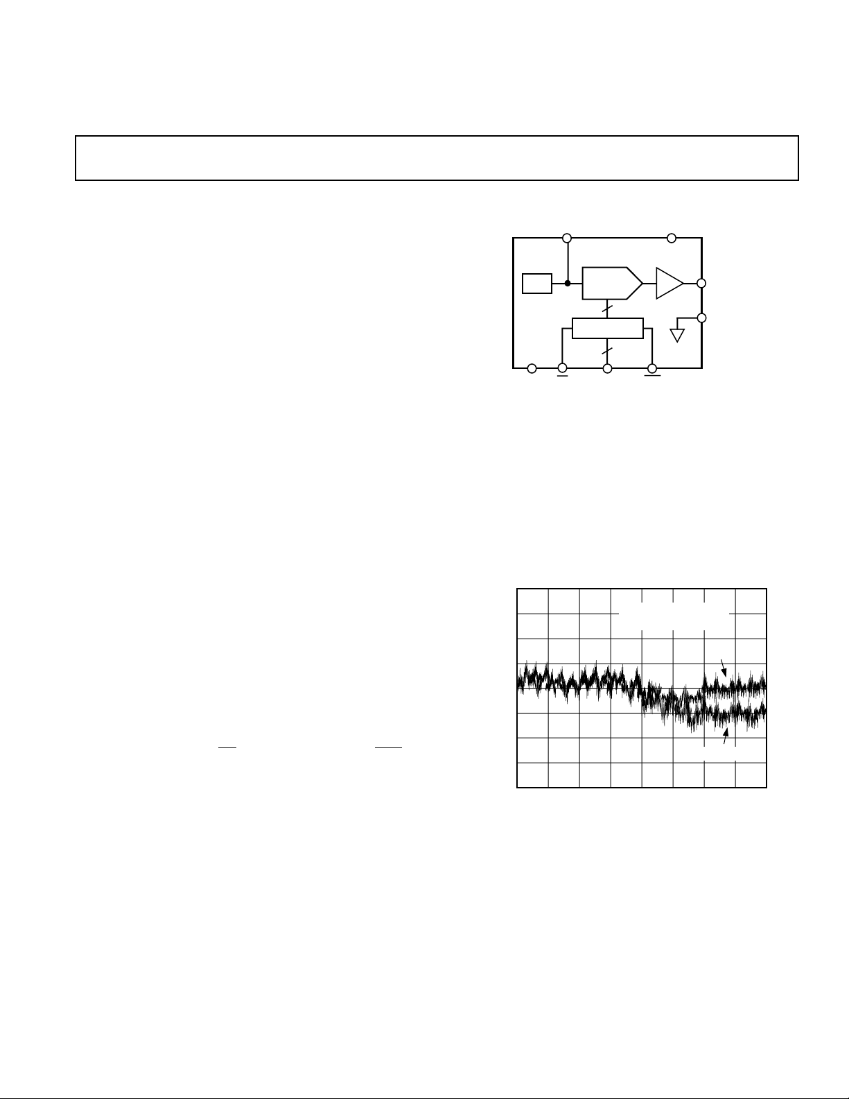
FUNCTIONAL BLOCK DIAGRAM
V
REFOUT
DAC-8562
DAC REGISTER
CE
12-BIT
DAC
DATA
12
12
REF
DGND
The DAC8562 is available in two different 20-pin packages,
plastic DIP and SOL-20. Each part is fully specified for operation over –40°C to +85°C, and the full +5 V ± 5% power supply
range.
For MIL-STD-883 applications, contact your local ADI sales
office for the DAC8562/883 data sheet which specifies operation over the –55°C to +125°C temperature range.
1
0.75
0.5
0.25
0
–0.25
LINEARITY ERROR — LSB
–0.5
–0.75
–1
0
VDD = +5V
T
A
DIGITAL INPUT CODE — Decimal
Figure 1. Linearity Error vs. Digital Input Code Plot
DD
V
AGND
CLR
= –55°C, +25°C, +125°C
–55°C
+25°C & +125°C
307220481024
OUT
4096
REV. A
Information furnished by Analog Devices is believed to be accurate and
reliable. However, no responsibility is assumed by Analog Devices for its
use, nor for any infringements of patents or other rights of third parties
which may result from its use. No license is granted by implication or
otherwise under any patent or patent rights of Analog Devices.
One Technology Way, P.O. Box 9106, Norwood, MA 02062-9106, U.S.A.
Tel: 617/329-4700 Fax: 617/326-8703

DAC8562–SPECIFICATIONS
ELECTRICAL CHARACTERISTICS
(@ VDD = +5.0 6 5%, RS = No Load, –408C ≤ TA ≤ +858C, unless otherwise noted)
Parameter Symbol Condition Min Typ Max Units
STATIC PERFORMANCE
Resolution N Note 2 12 Bits
Relative Accuracy INL E Grade –1/2 ± 1/4 +1/2 LSB
F Grade –1 ±3/4 +1 LSB
Differential Nonlinearity DNL No Missing Codes –1 ±3/4 +1 LSB
Zero-Scale Error V
Full-Scale Voltage V
ZSE
FS
Data = 000
Data - FFF
H
3
H
+1/2 +3 LSB
E Grade 4.087 4.095 4.103 V
F Grade 4.079 4.095 4.111 V
Full-Scale Tempco TCV
Notes 3, 4 ±16 ppm/°C
FS
ANALOG OUTPUT
Output Current I
OUT
Load Regulation at Half Scale LD
Capacitive Load C
L
REG
Data = 800
R
= 402 Ω to ∞, Data = 800
L
No Oscillation
H
4
±5 ±7mA
H
1 3 LSB
500 pF
REFERENCE OUTPUT
Output Voltage V
Output Source Current I
REF
REF
Line Rejection LN
Load Regulation LD
Note 5 5 7 mA
REJ
REGIREF
= 0 to 5 mA 0.1 %/mA
2.484 2.500 2.516 V
0.08 %/V
LOGIC INPUTS
Logic Input Low Voltage V
Logic Input High Voltage V
Input Leakage Current I
Input Capacitance C
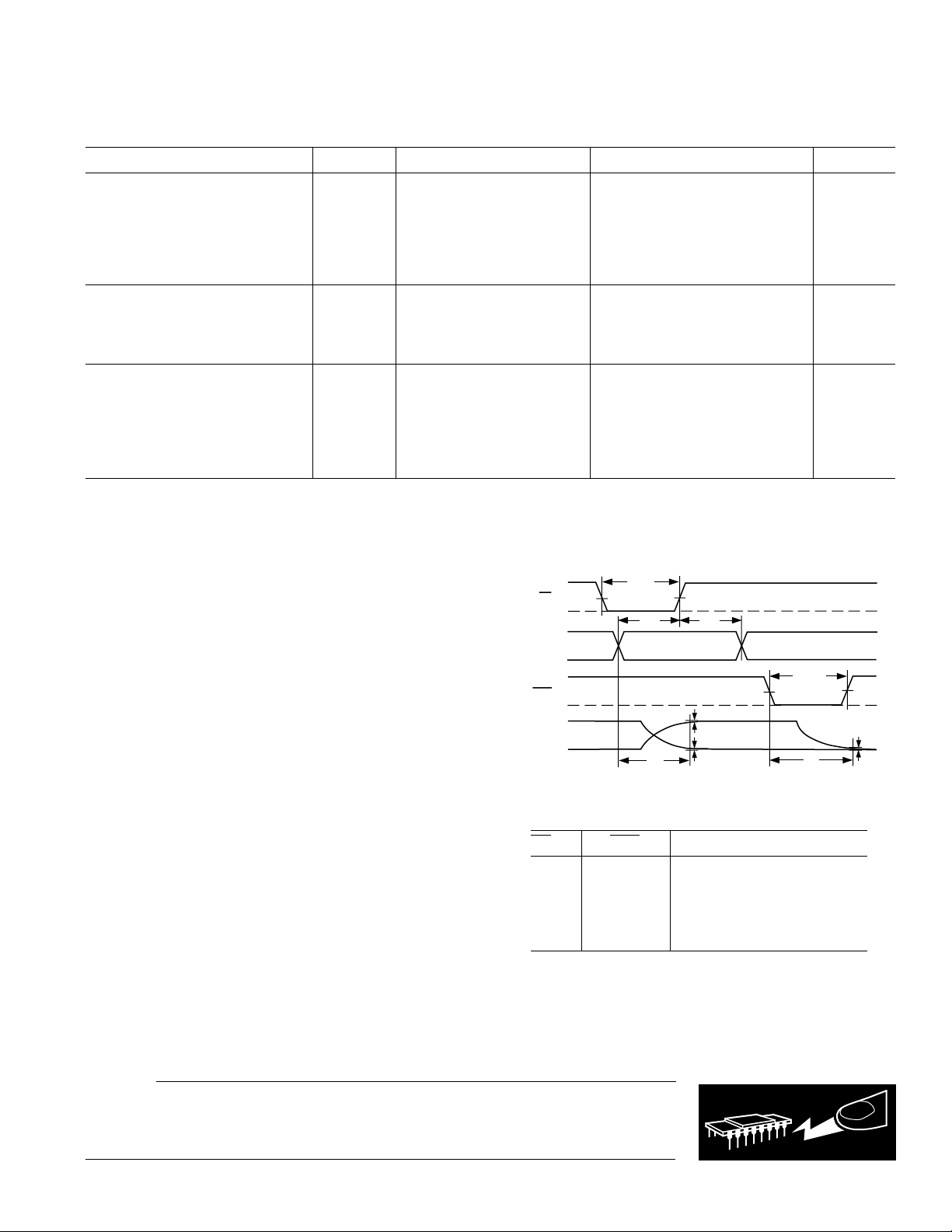
INTERFACE TIMING SPECIFICATIONS
1, 4
Chip Enable Pulse Width t
Data Setup t
Data Hold t
Clear Pulse Width t
AC CHARACTERISTICS
Voltage Output Settling Time
4
6
IL
IH
IL
IL
CEW
DS
DH
CLRW
t
S
2.4 V
Note 4 10 pF
30 ns
30 ns
10 ns
20 ns
To ±1 LSB of Final Value 16 µs
0.8 V
10 µA
Digital Feedthrough 35 nV sec
SUPPLY CHARACTERISTICS
Positive Supply Current I
Power Dissipation P
DD
DISS
VIH = 2.4 V, VIL = 0.8 V 3 6 mA
V
= 0 V, VDD = +5 V 0.6 1 mA
IL
VIH = 2.4 V, VIL = 0.8 V 15 30 mW
V
= 0 V, VDD = +5V 3 5 mW
IL
Power Supply Sensitivity PSS ∆VDD = ±5% 0.002 0.004 %/%
NOTES
1
All input control signals are specified with tr = tf = 5 ns (10% to 90% of +5 V) and timed from a voltage level of 1.6 V.
2
1 LSB = 1 mV for 0 to +4.095 V output range.
3
Includes internal voltage reference error.
4
These parameters are guaranteed by design and not subject to production testing.
5
Very little sink current is available at the REFOUT pin. Use external buffer if setting up a virtual ground.
6
The settling time specification does not apply for negative going transitions within the last 6 LSBs of ground. Some devices exhibit double the typical settling time in
this 6 LSB region.
Specifications subject to change without notice.
–2–
REV. A
1
0
0
0
1
1
FS
ZS
DB
11–0
V
OUT
t
CEW
t
DS
t
DH
DATA VALID
t
CLRW
t
S
t
S
±1 LSB
ERROR BAND
CE
CLR
DAC8562
(@ VDD = +5.0 V 6 5%, RL = No Load, TA = +258C, applies to part number DAC8562GBC only,
WAFER TEST LIMITS
Parameter Symbol Condition Min Typ Max Units
STATIC PERFORMANCE
Relative Accuracy INL –1 ±3/4 +1 LSB
Differential Nonlinearity DNL No Missing Codes –1 ±3/4 + 1 LSB
Zero-Scale Error V
Full-Scale Voltage V
Reference Output Voltage V
LOGIC INPUTS
Logic Input Low Voltage V
Logic Input High Voltage V
Input Leakage Current I
SUPPLY CHARACTERISTICS
Positive Supply Current I
Power Dissipation P
Power Supply Sensitivity PSS ∆VDD = ±5% 0.002 0.004 %/%
NOTE
1
Electrical tests are performed at wafer probe to the limits shown. Due to variations in assembly methods and normal yield loss, yield after packaging is not guaranteed
for standard product dice. Consult factory to negotiate specifications based on dice lot qualifications through sample lot assembly and testing.
unless otherwise noted)
ZSE
FS
REF
IL
IH
IL
DD
DISS
Data = 000
Data = FFF
H
H
4.085 4.095 4.105 V
+1/2 +3 LSB
2.490 2.500 2.510 V
0.8 V
2.4 V
10 µA
VIH = 2.4 V, VIL = 0.8 V 3 6 mA
V
= 0 V, VDD = +5 V 0.6 1 mA
IL
VIH = 2.4 V, VIL = 0.8 V 15 30 mW
V
= 0 V, VDD = +5 V 35mW
IL
ABSOLUTE MAXIMUM RATINGS*
VDD to DGND and AGND . . . . . . . . . . . . . . . . –0.3 V, +10 V
Logic Inputs to DGND . . . . . . . . . . . . . . .–0.3 V, V
V
to AGND . . . . . . . . . . . . . . . . . . . . .–0.3 V, VDD + 0.3 V
OUT
V
to AGND . . . . . . . . . . . . . . . . . .–0.3 V, VDD + 0.3 V
REFOUT
AGND to DGND . . . . . . . . . . . . . . . . . . . . . . . . . –0.3 V, V
I
Short Circuit to GND . . . . . . . . . . . . . . . . . . . . . . 50 mA
OUT
Package Power Dissipation . . . . . . . . . . . . . .(T
Thermal Resistance u
JA
+ 0.3 V
DD
max – TA)/u
J
DD
JA
20-Pin Plastic DIP Package (P) . . . . . . . . . . . . . . . . 74°C/W
20-Lead SOIC Package (S) . . . . . . . . . . . . . . . . . . . 89°C/W
Maximum Junction Temperature (T
max) . . . . . . . . . . 150°C
J
Operating Temperature Range . . . . . . . . . . . . .–40°C to +85°C
Storage Temperature Range . . . . . . . . . . . . . –65°C to +150°C
Lead Temperature (Soldering, 10 secs) . . . . . . . . . . . . +300°C
*Stresses above those listed under “Absolute Maximum Ratings” may cause
permanent damage to the device. This is a stress rating only and functional
operation of the device at these or any other conditions above those indicated in the
operational sections of this specification is not implied. Exposure to absolute
maximum rating conditions for extended periods may affect device reliability.
Figure 2. Timing Diagram
Table I. Control Logic Truth Table
CE CLR DAC Register Function
H H Latched
L H Transparent
↑
+ H Latched with New Data
X L Loaded with All Zeros
H
↑
+ Positive Logic Transition; X Don't Care.
↑
+ Latched All Zeros
CAUTION
ESD (electrostatic discharge) sensitive device. The digital control inputs are diode protected;
however, permanent damage may occur on unconnected devices subject to high energy electrostatic
fields. Unused devices must be stored in conductive foam or shunts. The protective foam should be
discharged to the destination socket before devices are inserted.
REV. A
–3–
WARNING!
ESD SENSITIVE DEVICE
DAC8562
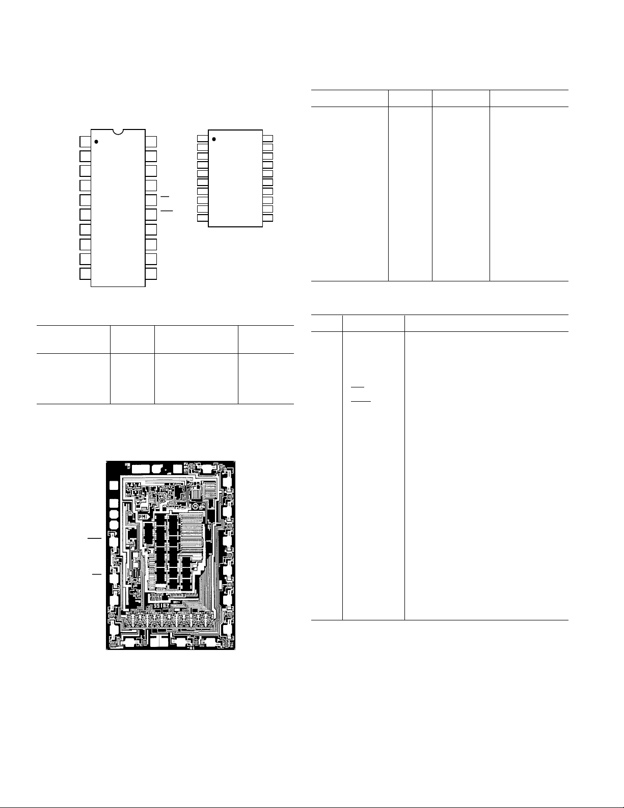
PIN CONFIGURATIONS
DB3
DB4
DB5
DB6
DB7
DB8
DB9
DB10
DB11
DGND
20-Pin P-DIP
(N-20)
1
2
3
4
DAC-8562
5
TOP VIEW
6
(Not to Scale)
7
8
9
10
NC = NO CONNECT
20
19
18
17
16
15
14
13
12
11
V
DD
DB2
DB1
DB0
CE
CLR
REFOUT
V
OUT
AGND
NC
SOL-20
(R-20)
1
DAC-8562
TOP VIEW
(Not to Scale)
ORDERING GUIDE
INL Temperature Package
Model (LSB) Range Option
DAC8562EP ±1/2 –40°C to +85°C N-20
DAC8562FP ±1 –40°C to +85°C N-20
DAC8562FS ±1 –40°C to +85°C R-20
DAC8562GBC ±1 +25°C Dice
DICE CHARACTERISTICS
AGND
13
V
OUT
REFOUT
14
15
CLR
16
CE
17
DB0
18
DB1
19
DB2
SUBSTRATE IS COMMON WITH VDD.
TRANSISTOR COUNT: 524
DIE SIZE: 0.70 X 0.105 INCH; 7350 SQ MILS
12
DGND
20 1
V
DD
DB11
10
9
DB10
8
7
DB9
6
DB8
5
DB7
DB6
4
3
DB5
2
DB4DB3
Table II. Nominal Output Voltage vs. Input Code
Binary Hex Decimal Output (V)
0000 0000 0000 000 0 0.000 Zero Scale
0000 0000 0001 001 1 0.001
0000 0000 0010 002 2 0.002
0000 0000 1111 00F 15 0.015
0000 0001 0000 010 16 0.016
0000 1111 1111 0FF 255 0.255
0001 0000 0000 100 256 0.256
0001 1111 1111 1FF 511 0.511
0010 0000 0000 200 512 0.512
0011 1111 1111 3FF 1023 1.023
0100 0000 0000 400 1024 1.024
0111 1111 1111 7FF 2047 2.047
1000 0000 0000 800 2048 2.048 Half Scale
1100 0000 0000 C00 3072 3.072
1111 1111 1111 FFF 4095 4.095 Full Scale
PIN DESCRIPTIONS
Pin Name Description
20 V
DD
Positive supply. Nominal value
+5 volts, ±5%.
1-9 DB0-DB11 Twelve Binary Data Bit inputs. DB11
17-19 is the MSB and DB0 is the LSB.
16
15
CE Chip Enable. Active low input.
CLR Active low digital input that clears the
DAC register to zero, setting the DAC
to minimum scale.
8 DGND Digital ground for input logic.
12 AGND Analog Ground. Ground reference for
the internal bandgap reference voltage,
the DAC, and the output buffer.
13 V
OUT
Voltage output from the DAC. Fixed
output voltage range of 0 V to 4.095 V
with 1 mV/LSB. An internal tempera-
ture stabilized reference maintains a
fixed full-scale voltage independent of
time, temperature and power supply
variations.
14 REFOUT Nominal 2.5 V reference output volt-
age. This node must be buffered if re-
quired to drive external loads.
11 NC No Connection. Leave pin floating.
–4–
REV. A
DAC8562
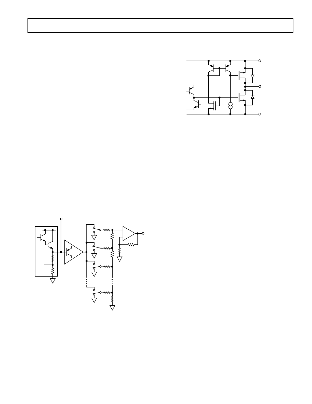
V
DD
V
OUT
AGND
N-CH
P-CH
OPERATION
The DAC8562 is a complete ready to use 12-bit digital-toanalog converter. Only one +5 V power supply is necessary for
operation. It contains a voltage-switched, 12-bit, laser-trimmed
digital-to-analog converter, a curvature-corrected bandgap reference, a rail-to-rail output op amp, and a DAC register. The parallel data interface consists of 12 data bits, DB0–DB11, and a
active low
will set all DAC register bits to zero causing the V
CE strobe. In addition, an asynchronous CLR pin
to be-
OUT
come zero volts. This function is useful for power on reset or
system failure recovery to a known state.
D/A CONVERTER SECTION
The internal DAC is a 12-bit voltage-mode device with an output that swings from AGND potential to the 2.5 volt internal
bandgap voltage. It uses a laser trimmed R-2R ladder which is
switched by N channel MOSFETs. The output voltage of the
DAC has a constant resistance independent of digital input
code. The DAC output (not available to the user) is internally
connected to the rail-to-rail output op amp.
AMPLIFIER SECTION
The internal DAC’s output is buffered by a low power consumption precision amplifier. This low power amplifier contains
a differential PNP pair input stage which provides low offset
voltage and low noise, as well as the ability to amplify the zeroscale DAC output voltages. The rail-to-rail amplifier is configured in a gain of 1.6384 (= 4.095 V/2.5 V) in order to set the
4.095 volt full-scale output (1 mV/LSB). See Figure 3 for an
equivalent circuit schematic of the analog section.
REFOUT
BANDGAP
REFERENCE
2.5V
VOLTAGE SWITCHED 12-BIT
R-2R D/A CONVERTER
BUFFER
SPDT
N ch FET
SWITCHES
RAIL-TO-RAIL
OUTPUT
2R
R
2R
R
2R
2R
2R
AMPLIFIER
R2
R1
AV = 4.096/2.5
= 1.636V/V
V
OUT
Figure 3. Equivalent DAC8562 Schematic of
Analog Portion
The op amp has a 16 µs typical settling time to 0.01%. There
are slight differences in settling time for negative slewing signals
versus positive. See the oscilloscope photos in the Typical Performances section of this data sheet.
OUTPUT SECTION
The rail-to-rail output stage of this amplifier has been designed
to provide precision performance while operating near either
power supply. Figure 4 shows an equivalent output schematic of
the rail-to-rail amplifier with its N channel pull down FETs that
will pull an output load directly to GND. The output sourcing
current is provided by a P channel pull-up device that can supply GND terminated loads, especially important at the –5%
supply tolerance value of 4.75 volts.
Figure 4. Equivalent Analog Output Circuit
Figures 5 and 6 in the typical performance characteristics section provide information on output swing performance near
ground and full scale as a function of load. In addition to resistive load driving capability, the amplifier has also been carefully
designed and characterized for up to 500 pF capacitive load
driving capability.
REFERENCE SECTION
The internal 2.5 V curvature-corrected bandgap voltage reference is laser trimmed for both initial accuracy and low temperature coefficient. The voltage generated by the reference is
available at the REFOUT pin. Since REFOUT is not intended
to drive external loads, it must be buffered–refer to the applications section for more information. The equivalent emitter follower output circuit of the REFOUT pin is shown in Figure 3.
Bypassing the REFOUT pin is not required for proper operation. Figure 7 shows broadband noise performance.
POWER SUPPLY
The very low power consumption of the DAC8562 is a direct
result of a circuit design optimizing use of the CBCMOS process. By using the low power characteristics of the CMOS for
the logic, and the low noise, tight matching of the complementary bipolar transistors, good analog accuracy is achieved.
For power-consumption sensitive applications it is important to
note that the internal power consumption of the DAC8562 is
strongly dependent on the actual logic-input voltage-levels
present on the DB0–DB11,
CE and CLR pins. Since these inputs are standard CMOS logic structures, they contribute static
power dissipation dependent on the actual driving logic V
V
voltage levels. The graph in Figure 9 shows the effect on to-
OL
OH
and
tal DAC8562 supply current as a function of the actual value of
input logic voltage. Consequently for optimum dissipation use
of CMOS logic versus TTL provides minimal dissipation in the
static state. A V
= 0 V on the DB0–DB11 pins provides the
INL
lowest standby dissipation of 600 µA with a +5 V power supply.
REV. A
–5–

DAC8562
80
–100
–60
–80
1
–20
–40
0
20
40
60
32
OUTPUT VOLTAGE – Volts
OUTPUT CURRENT – mA
POS0
CURRENT0
LIMIT0
NEG
CURRENT
LIMIT
DATA = 800H
R
L
TIED TO +2V
As with any analog system, it is recommended that the
DAC8562 power supply be bypassed on the same PC card that
contains the chip. Figure 10 shows the power supply rejection
versus frequency performance. This should be taken into account when using higher frequency switched-mode power supplies with ripple frequencies of 100 kHz and higher.
One advantage of the rail-to-rail output amplifier used in the
DAC8562 is the wide range of usable supply voltage. The part is
fully specified and tested over temperature for operation from
+4.75 V to +5.25 V. If reduced linearity and source current capability near full scale can be tolerated, operation of the
DAC8562 is possible down to +4.3 volts. The minimum operating supply voltage versus load current plot, in Figure 11, provides information for operation below V
= +4.75 V.
DD
Typical Performance Characteristics
5
4
3
2
OUTPUT VOLTAGE – Volts
1
0
10
RL TIED TO +5V
DATA = 000H
100 100k10k1k
LOAD RESISTANCE – Ω
VDD = +5V
T
= +25°C
A
RL TIED TO AGND
RL TIED TO AGND
D = FFFH
DATA = FFFH
Figure 5. Output Swing vs. Load
100
VDD = +5V
DATA = 000H
10
TA = +85°C
1
0.1
OUTPUT PULLDOWN VOLTAGE – mV
0.01
1
10 1000100
OUTPUT SINK CURRENT – µA
Figure 6. Pull-Down Voltage vs.
Output Sink Current Capability
TIMING AND CONTROL
The DAC8562 has a 12-bit DAC register that simplifies interface to a 12-bit (or wider) data bus. The latch is controlled by
the Chip Enable (
a data bus, wiring
CE) input. If the application does not involve
CE low allows direct operation of the DAC.
The data latch is level triggered and acquires data from the data
bus during the time period when
high, the data is latched into the register and held until
CE is low. When CE goes
CE re-
turns low. The minimum time required for the data to be
present on the bus before
setup time (t
) as seen in Figure 2. The data hold time (tDH) is
DS
CE returns high is called the data
the amount of time that the data has to remain on the bus after
CE goes high. The high speed timing offered by the DAC8562
provides for direct interface with no wait states in all but the
fastest microprocessors.
TA = +25°C
TA = –40°C
Figure 7. I
OUT
vs. V
OUT
100
90
10
0%
OUTPUT NOISE VOLTAGE – 500µV/DIV
Figure 8. Broadband Noise
50mV
TIME = 1ms/DIV
1ms
TA = 25°C
NBW = 630kHz
5
4
3
2
SUPPLY CURRENT – mA
1
0
0
LOGIC VOLTAGE VALUE – Volts
VDD = +5V
= +25°C
T
A
3241
5
Figure 9. Supply Current vs. Logic
Input Voltage
–6–
100
VDD = +5V ±200mV AC
= +25°C
T
80
60
40
20
POWER SUPPLY REJECTION – dB
0
10
A
DATA = FFFH
100
FREQUENCY – Hz
100k10k1k
Figure 10. Power Supply Rejection
vs. Frequency
REV. A

5.0
0
5
VDD = +5V
T
A
= +25°C
OUTPUT VOLTAGE
1mV/DIV
DATA
TIME – 10µs/DIV
16µs
5
0
4
3
2
1
0
10
90
100
0%
TIME = 20µs/DIV
20µs
1V
INPUT
OUTPUT
5V
V
DD
= +5V
T
A
= +25°C
+25°C & +85°C
VDD = +5V
T
A
= –40°C, 25°C, +85°C
–40°C
2.0
1.5
1.0
0.5
0.0
–0.5
–1.0
–1.5
–2.0
0 1024 1536 2048 2560 3072 3584 4096512
DIGITAL INPUT CODE – Decimal
LINEARITY ERROR – LSB
3
–1
125
0
–25–50
1
2
1007550250
TEMPERATURE – °C
ZERO-SCALE – mV
DATA = 000H
NO LOAD
V
DD
= +5.0V
4.8
4.6
MIN – Volts
4.4
DD
V
4.2
∆VFS ≤ 1 LSB
DATA = FFFH
= +25°C
T
A
PROPER OPERATION
WHEN V
DD
VOLTAGE ABOVE
CURVE
SUPPLY
2.048
2.038
– Volts
2.028
OUT
V
2.018
CE
DAC8562
5
0
DATA = 204810 TO 2047
10
4.0
0.04
0.01 0.1 101.0
OUTPUT LOAD CURRENT – mA
0.4 4.0
Figure 11. Minimum Supply
Voltage vs. Load
5
DATA
0
16µs
VDD = +5V
T
= +25°C
1mV/DIV
OUTPUT VOLTAGE
A
TIME – 10µs/DIV
Figure 14. Output Voltage Rise
Time Detail
TIME – 200ns/DIV
Figure 12. Midscale Transition
Performance
Figure 15. Output Voltage Fall
Time Detail
Figure 13. Large Signal Settling
Time
Figure 16. Linearity Error vs.
Digital Code
REV. A
50
TUE = INL+ZS+FS
Σ
SS = 300 UNITS
T
= +25°C
40
A
30
20
NUMBER OF UNITS
10
0
–6–8
–2–4
2
TOTAL UNADJUSTED ERROR – LSB
Figure 17. Total Unadjusted
Error Histogram
4.125
4.115
VDD = +5V
NO LOAD
SS = 300 PCS
4.105
4.095
FULL-SCALE OUTPUT –Volts
4.085
1610 1268 1440
4.075
–50 –25 0 25 50 75 100 125
TEMPERATURE –
Figure 18. Full-Scale Voltage
vs. Temperature
AVG +1σ
AVG –1σ
°
C
AVG
Figure 19. Zero-Scale Voltage vs.
Temperature
–7–

DAC8562
10
8
6
4
2
0
–2
–4
–6
–8
–10
–50 –25 0 25 50 75 100 125
AVG +1σ
AVG –1σ
X
VDD = +5V
SAMPLE SIZE = 300
TEMPERATURE –
°C
V
REF OUT
ERROR –mV
DAC8562
–Typical Performance Characteristics
10
Hz
1
0.1
OUTPUT NOISE DENSITY – µV/
0.01
10
100
FREQUENCY – Hz
VDD = +5V
= 25°C
T
A
DATA = FFF
Figure 20. Output Voltage Noise
Density vs. Frequency
2V
100
90
V
DD
0V
V
REF
0V
10
0%
2V
TIME = 1µs/DIV
TA = +25°C
=
R
L
∞
1µs
5
4
H
100k10k1k
3
READINGS NORMALIZED
2
TO ZERO HOUR TIME POINT
1
0
–1
–2
–3
OUTPUT VOLTAGE CHANGE – mV
–4
135 UNITS TESTED
–5
200
0
HOURS OF OPERATION AT +125°C
AVG
VDD = +5V
DATA = FFF
RANGE
1000600 800400
H
1200
Figure 21. Long-Term Drift
Accelerated by Burn-In
DATA
OUT
V
1
0
A4 0.040 V DLY
100
90
5mV/DIV
10
0%
5mV
5V
CE = HIGH
B
Lw
TIME = 20µs/DIV
13.82
5µs
µs
8
7
6
5
4
3
2
SUPPLY CURRENT – mA
1
0
VDD = +5.0V
VDD = +4.75V
–25–50
TEMPERATURE – °C
VDATA = +2.4V
NO LOAD
VDD = +5.25V
Figure 22. Supply Current vs.
Temperature
125
1007550250
Figure 23. Reference Startup vs.
Time
0.005
0.004
0.003
0.002
0.001
REF LOAD REGULATION – %/mA
0.000
Figure 26. Reference Load
Regulation vs. Temperature
σ
AVG + 3
AVG
AVG – 3
VDD = +5V
IL = 5mA
∆
SAMPLE SIZE = 302 PCS
0
–25
–50
TEMPERATURE – °C
Figure 24. Digital Feedthrough vs.
Time
0.10
0.08
0.06
AVG + 3 σ
σ
REF LINE REGULATION – %/Volt
125
25
10050 75
0.04
0.02
0.00
–50
AVG
AVG – 3
–25
0
TEMPERATURE – °C
Figure 25. Reference Error vs.
Temperature
VDD = +4.75 TO +5.25V
SAMPLE SIZE = 302 PCS
σ
125
25
10050 75
Figure 27. Reference Line
Regulation vs. Temperature
–8–
REV. A

DAC8562
15
16
DGND
AGND
V
DD
DATA
13
DAC-8562
12
10µF
0.1µF
V
OUT
TO OTHER
ANALOG CIRCUITS
20
+5V
10
TO POWER GROUND
CE
CLR
APPLICATIONS SECTION
Power Supplies, Bypassing, and Grounding
All precision converter products require careful application of
good grounding practices to maintain full-rated performance.
Because the DAC8562 has been designed for +5 V applications,
it is ideal for those applications under microprocessor or microcomputer control. In these applications, digital noise is prevalent; therefore, special care must be taken to assure that its
inherent precision is maintained. This means that particularly
good engineering judgment should be exercised when addressing the power supply, grounding, and bypassing issues using the
DAC8562.
The power supply used for the DAC8562 should be well filtered
and regulated. The device has been completely characterized for
a +5 V supply with a tolerance of ± 5%. Since a +5 V logic supply is almost universally available, it is not recommended to
connect the DAC directly to an unfiltered logic supply without
careful filtering. Because it is convenient, a designer might be
inclined to tap a logic circuit s supply for the DAC’s supply.
Unfortunately, this is not wise because fast logic with nanosecond transition edges induces high current pulses. The high transient current pulses can generate glitches hundreds of millivolts
in amplitude due to wiring resistances and inductances. This
high frequency noise will corrupt the analog circuits internal to
the DAC and cause errors. Even though their spike noise is
lower in amplitude, directly tapping the output of a +5 V system
supplies can cause errors because these supplies are of the
switching regulator type that can and do generate a great deal of
high frequency noise. Therefore, the DAC and any associated
analog circuitry should be powered directly from the system
power supply outputs using appropriate filtering. Figure 28
illustrates how a clean, analog-grade supply can be generated
from a +5 V logic supply using a differential LC filter with separate power supply and return lines. With the values shown, this
filter can easily handle 100 mA of load current without saturating the ferrite cores. Higher current capacity can be achieved
with larger ferrite cores. For lowest noise, all electrolytic capacitors should be low ESR (Equivalent Series Resistance) type.
FERRITE BEADS:
TTL/CMOS
LOGIC
CIRCUITS
2 TURNS, FAIR-RITE
#2677006301
100µF
ELECT.
10-22µF
TANT.
0.1µF
CER.
+5V
The DAC8562 includes two ground connections in order to
minimize system accuracy degradation arising from grounding
errors. The two ground pins are designated DGND (Pin 10)
and AGND (Pin 12). The DGND pin is the return for the digital circuit sections of the DAC and serves as their input threshold reference point. Thus DGND should be connected to the
same ground as the circuitry that drives the digital inputs.
Pin 12, AGND, serves as the supply rail for the internal voltage
reference and the output amplifier. This pin should also serve as
the reference point for all analog circuitry associated with the
DAC8562. Therefore, to minimize any errors, it is recommended that the AGND connection of the DAC8562 be connected to a high quality analog ground. If the system contains
any analog signal path carrying a significant amount of current,
then that path should have its own return connection to Pin 12.
It is often advisable to maintain separate analog and digital
grounds throughout a complete system, tying them common to
one place only. If the common tie point is remote and an accidental disconnection of that one common tie point were to
occur due to card removal with power on, a large differential
voltage between the two commons could develop. To protect
devices that interface to both digital and analog parts of the system, such as the DAC8562, it is recommended that the common ground tie points be provided at each such device. If only
one system ground can be connected directly to the DAC8562,
it recommended that the analog common be used. If the
system’s AGND has suitably low impedance, then the digital
signal currents flowing in it should not seriously affect the
ground noise. The amount of digital noise introduced by connecting the two grounds together at the device will not adversely
affect system performance due to loss of digital noise immunity.
Generous bypassing of the DAC’s supply goes a long way in reducing supply line-induced errors. Local supply bypassing consisting of a 10 µF tantalum electrolytic in parallel with a 0.1 µF
ceramic is recommended. The decoupling capacitors should be
connected between the DAC’s supply pin (Pin 20) and the analog ground (Pin 12). Figure 29 shows how the DGND, AGND,
and bypass connections should be made to the DAC8562.
+5V
POWER SUPPLY
Figure 28. Properly Filtering a +5 V Logic Supply
Can Yield a High Quality Analog Supply
REV. A
+5V
RETURN
Figure 29. Recommended Grounding and Bypassing
Scheme for the DAC-8562
–9–

DAC8562
15
16
DGND
AGND
DATA
DAC-8562
13
V
OUT
+12V OR +15V
10
CE
CLR
1
12
0.1µF
4
REF-02
6
2
0.1µF
15
16
DGND
AGND
V
DD
DATA
DAC-8562
13
0.1µF
V
OUT
+5V
10
CE
CLR
20
12
200µA MAX
V–
Unipolar Output Operation
This is the basic mode of operation for the DAC8562. As shown
in Figure 30, the DAC8562 has been designed to drive loads as
low as 820 Ω in parallel with 500 pF. The code table for this operation is shown in Table III.
+5V
V
20
DD
AGND
12
10µF
0V ≤ V
≤ 4.095V
13
820
Ω
OUT
500pF
0.1µF
DATA
DAC-8562
CE
16
15
CLR
DGND
10
Figure 30. Unipolar Output Operation
Table III. Unipolar Code Table
Hexadecimal Number Decimal Number Analog Output
in DAC Register in DAC Register Voltage (V)
FFF 4095 +4.095
801 2049 +2.049
800 2048 +2.048
7FF 2047 +2.047
000 0 0
Operating the DAC8562 on +12 V or +15 V Supplies Only
Although the DAC8562 has been specified to operate on a
single, +5 V supply, a single +5 V supply may not be available in
many applications. Since the DAC8562 consumes no more than
6 mA, maximum, then an integrated voltage reference, such as
the REF02, can be used as the DAC8562 +5 V supply. The
configuration of the circuit is shown in Figure 31. Notice that
the reference’s output voltage requires no trimming because of
the REF02’s excellent load regulation and tight initial output
voltage tolerance. Although the maximum supply current of the
DAC8562 is 6 mA, local bypassing of the REF02’s output with
at least 0. 1 µF at the DAC’s voltage supply pin is recommended
to prevent the DAC’s internal digital circuits from affecting the
DAC’s internal voltage reference.
Figure 31. Operating the DAC8562 on +12 V or +15 V
Supplies Using a REF02 Voltage Reference
Measuring Offset Error
One of the most commonly specified endpoint errors associated
with real-world nonideal DACs is offset error.
In most DAC testing, the offset error is measured by applying
the zero-scale code and measuring the output deviation from
0 volt. There are some DACs where offset errors may be present
but not observable at the zero scale because of other circuit limitations (for example, zero coinciding with single supply ground).
In these DACs, nonzero output at zero code cannot be read as
the offset error. In the DAC8562, for example, the zero-scale error is specified to be +3 LSBs. Since zero scale coincides with
zero volt, it is not possible to measure negative offset error.
By adding a pull-down resistor from the output of the
DAC8562 to a negative supply as shown in Figure 32, offset errors can now be read at zero code. This configuration forces the
output P-channel MOSFET to source current to the negative
supply thereby allowing the designer to determine in which direction the offset error appears. The value of the resistor should
be such that, at zero code, current through the resistor is 200 µA
maximum.
Figure 32. Measuring Zero-Scale or Offset Error
–10–
REV. A

CE
CLR
DATA
10µF
16
15
+5V
20
V
DD
DAC-8562
REFOUT
AGND
DGND
10
V
12
0.1µF
OUT
DAC8562
8
4
FULL SCALE
ADJUST
P2
Ω
500
1
–5V ≤ VO ≤ +5V
R4
Ω
23.7k
R1
Ω
13
14
R5
10k
10k
R2
12.7k
–2.5V
R6
10k
Ω
Ω
6
5
A2
7
R3
247k
P1
Ω
10k
ZERO SCALE
ADJUST
Ω
A1, A2 = 1/2 OP-295
+5V
2
A1
3
–5V
Figure 33. Bipolar Output Operation
Bipolar Output Operation
Although the DAC8562 has been designed for single supply operation, bipolar operation is achievable using the circuit illustrated in Figure 33. The circuit uses a single supply, rail-to-rail
OP295 op amp and the DAC’s internal +2.5 V reference to generate the –2.5 V reference required to level-shift the DAC output voltage. The circuit has been configured to provide an
output voltage in the range –5 V ≤ V
≤ +5 V and is coded in
OUT
complementary offset binary. Although each DAC LSB corresponds to 1 mV, each output LSB has been scaled to 2.44 mV.
Table IV provides the relationship between the digital codes and
output voltage.
The transfer function of the circuit is given by:
V
=−1mV × Digital Code ×
O
R4
R1
+2.5 ×
R4
R2
and, for the circuit values shown, becomes:
VO= –2.44 mV × Digital Code + 5 V
Table IV. Bipolar Code Table
Hexadecimal Number Decimal Number Analog Output
in DAC Register in DAC Register Voltage (V)
FFF 4095 –4 9976
801 2049 –2.44E–3
800 2048 0
7FF 2047 +2.44E–3
000 0 +5
To maintain monotonicity and accuracy, R1, R2, R4, R5, and
R6 should be selected to match within 0.01% and must all be of
the same (preferably metal foil) type to assure temperature coefficient matching. Mismatching between R1 and R2 causes offset
and gain errors while an R4 to R1 and R2 mismatch yields gain
errors.
For applications that do not require high accuracy, the circuit illustrated in Figure 34 can also be used to generate a bipolar
output voltage. In this circuit, only one op amp is used and no
potentiometers are used for offset and gain trim The output
voltage is coded in offset binary and is given by:
VO=1 mV × Digital Code ×
–REFOUT ×
R4
R3 + R4
R2
R1
× 1 +
R2
R1
For the ±2 5 V output range and the circuit values shown in the
table, the transfer equation becomes:
VO=1. 2 2 mV × Digital Code –2.5V
Similarly, for the ±5 V output range, the transfer equation becomes:
VO= 2. 44 mV × Digital Code –5V
Note that, for ±5 V output voltage operation, R5 is required as a
pull-down for REFOUT. Or, REFOUT can be buffered by an
op amp configured as a follower that can source and sink current.
+5V
0.1µF
R2
2
A1
3
R4
A1 = 1/2 OP-295
R3
R2
10k
10k
10k
20k
+5V
8
4
–5V
1
R4
15.4k + 274
43.2k + 499
V
O
CE
CLR
DATA
16
15
20
V
DD
REFOUT
DAC-8562
AGND
DGND
10
OUT
R5
4.99k
R1
10k
10k
R1
Ω
R3
14
V
13
OUT
12
V
RANGE
±2.5V
±5V
Figure 34. Bipolar Output Operation Without
Trim Version 1
REV. A
–11–

DAC8562
15
16
DGND
AGND
DATA
DAC-8562
13
+15V
10
CE
CLR
20
12
0.1µF
4
REF-02
6
2
0.1µF
18k
10pF
470k
P1
100kΩ
10M
OFFSET
TRIM
47pF
SYMMETRY
TRIM
P2
500kΩ
V
OUT
+15V
–15V
30k
+15V
–15V
0.1µF
0.1µF
+15V
18k
V
IN
1
2
3
4
5
6
7
8
16
15
14
13
12
11
10
9
SSM-2018
+5V
C
CON
1µF
R6
825
R7
1kΩ
*
0V ≤ VC ≤ +2.24V
* – PRECISION RESISTOR PT146
1kΩ COMPENSATOR
Ω
Ω
Ω
Ω
Ω
Ω
Alternatively, the output voltage can be coded in complementary
offset binary using the circuit in Figure 35. This configuration
eliminates the need for a pull-down resistor or an op amp for
REFOUT The transfer equation of the circuit is given by:
VO= –1 mV × Digital Code ×
×
R4
R3 + R4
× 1 +
R2
R1
R2
R1
+ REFOUT
and, for the values shown, becomes:
VO=−2.44 mV × Digital Code + 5 V
R2
R1
V
O
R3
R1 = R3 = 10k
R4
O
R2
23.7k + 715
R4
13.7k + 169
Ω
Ω
DAC-8562
REFOUT
V
OUT
V
RANGE
±5V
Figure 35 Bipolar Output Operation Without
Trim Version 2
Generating a Negative Supply Voltage
Some applications may require bipolar output configuration, but
only have a single power supply rail available. This is very common in data acquisition systems using microprocessor-based systems. In these systems, only +12 V, +15 V, and/or +5 V are
available. Shown in Figure 36 is a method of generating a negative supply voltage using one CD4049, a CMOS hex inverter,
operating on +12 V or +15 V. The circuit is essentially a charge
pump where two of the six are used as an oscillator. For the values shown, the frequency of oscillation is approximately 3.5 kHz
and is fairly insensitive to supply voltage because R1 > 2 3 R2.
The remaining four inverters are wired in parallel for higher output current. The square-wave output is level translated by C2 to
a negative-going signal, rectified using a pair of 1N4001s, and
then filtered by C3. With the values shown, the charge pump
will provide an output voltage of –5 V for current loading in the
range 0.5 mA ≤ I
0.5 mA ≤ I
INVERTERS = CD4049
3254
R1
510k
Audio Volume Control
The DAC8562 is well suited to control digitally the gain or
attenuation of a voltage controlled amplifiers. In professional
≤ 7 mA with a +12 V supply.
OUT
R2
5.1k
Ω
0.02µF
≤ 10 mA with a +15 V supply and
OUT
Ω
C1
6
7
910
11 12
14 15
C2
47µF
D2
1N4001
D1
1N4001
R3
470
C3
47µF
Ω
Figure 36. Generating a –5 V Supply When
Only +12 V or +15 V Are Available
1N5231
5.1V
ZENER
–5V
audio mixing consoles, music synthesizers, and other audio processors, VCAs, such as the SSM2018, adjust audio channel gain and
attenuation from front panel potentiometers. The VCA provides a
clean gain transition control of the audio level when the slew rate of
the analog input control voltage, V
, is properly chosen. The cir-
C
cuit in Figure 37 illustrates a volume control application using the
DAC8562 to control the attenuation of the SSM2018.
Figure 37. Audio Volume Control
Since the supply voltage available in these systems is typically
±15 V or ±18 V, a REF02 is used to supply the +5 V required
to power the DAC. No trimming of the reference is required because of the reference’s tight initial tolerance and low supply
current consumption of the DAC8562. The SSM2018 is configured as a unity-gain buffer when its control voltage equals
0 volt. This corresponds to a 000
code from the DAC8562.
H
Since the SSM2018 exhibits a gain constant of –28 mV/dB
(typical), the DAC’s full-scale output voltage has to be scaled
down by R6 and R7 to provide 80 dB of attenuation when the
digital code equals FFF
. Therefore, every DAC LSB corre-
H
sponds to 0.02 dB of attenuation. Table V illustrates the attenuation versus digital code of the volume control circuit.
Table V. SSM2018 VCA Attenuation vs.
DAC8562 Input Code
Hexadecimal Number Control Voltage VCA Attenuation
in DAC Register (V) (dB)
000 0 0
400 +0.56 20
800 +1.12 40
C00 +1.68 60
FFF +2.24 80
–12–
REV. A

DAC8562
To compensate for the SSM2018’s gain constant temperature
coefficient of –3300 ppm/°C, a 1 kΩ, temperature-sensitive
resistor (R7) manufactured by the Precision Resistor Company with a temperature coefficient of +3500 ppm/°C is used.
A C
of 1 µF provides a control transition time of 1 ms which
CON
yields a click-free change in the audio channel attenuation. Symmetry and offset trimming details of the VCA can be found in
the SSM2018 data sheet.
Information regarding the PT146 1 kΩ “Compensator” can be
obtained by contacting:
Precision Resistor Company, Incorporated
10601 75th Street North
Largo, FL 34647
(813) 541-5771
A High-Compliance, Digitally Controlled Precision Current Source
The circuit in Figure 38 shows the DAC8562 controlling a
high-compliance, precision current source using an AMP05 instrumentation amplifier. The AMP05’s reference pin becomes
the input, and the “old” inputs now monitor the voltage across a
precision current sense resistor, R
. Voltage gain is set to unity,
CS
so the transfer function is given by the following equation:
V
I
OUT
If R
equals 100 Ω, the output current is limited to +10 mA
CS
IN
=
R
CS
with a 1 V input. Therefore, each DAC LSB corresponds to
2.4 µA. If a bipolar output current is required, then the circuit
in Figure 33 can be modified to drive the AMP05’s reference
pin with a ±1 V input signal.
Potentiometer P1 trims the output current to zero with the input at 0 V. Fine gain adjustment can be accomplished by adjusting R1 or R2.
A Digitally Programmable Window Detector
A digitally programmable, upper/lower limit detector using two
DAC8562s is shown in Figure 39. The required upper and
lower limits for the test are loaded into each DAC individually
by controlling HDAC/
LDAC. If a signal at the test input is not
within the programmed limits, the output will indicate a logic
zero which will turn the red LED on.
100k
R1
17
18
+15V
2
REF-02
4
R2
5kΩ
7
AMP-05
1
4
6
CLR
100kΩ
CE
DATA
5
P1
16
15
2
0.1µF
6
9
11
0.1µF
–15V
DAC-8562
DGND
10
+15V
12
20
0.1µF
8
AGND
12
0.1µF
R
CS
100Ω
10
0mA ≤ I
2.4µA/ LSB
R3
3k
13
R4
1k
OUT
≤ 10mA
Figure 38. A High-Compliance, Digitally Controlled
Precision Current Source
REV. A
74HC05
HDAC/LDAC
CLR
1/6
V
IN
+5V
0.1µF
13
3
5
C1
4
7
C2
6
12
13
C1, C2 = 1/4 CMP-404
2
1
+5V
+5V
0.1µF
1k
Ω
DATA
16
DAC-8562
15
DGND AGND
16
DAC-8562
15
DGND AGND
20
12
10
+5V
0.1µF
20
10
12
Figure 39. A Digitally Programmable Window Detector
–13–
+5V
R1
604Ω
RED LED
2
1
PASS/FAIL
3
T1
1/6
74HC05
4
+5V
R2
604Ω
GREEN LED
T1

DAC8562
Decoding Multiple DAC8562s
The CE function of the DAC8562 can be used in applications
to decode a number of DACs. In this application, all DACs receive the same input data; however, only one of the DACs’
CE
input is asserted to transfer its parallel input register contents
into the DAC. In this circuit, shown in Figure 40, the
CE timing is generated by a 74HC139 decoder and should follow the
DAC8562’s standard timing requirements. To prevent timing
errors, the 74HC139 should not be activated by its
ENABLE
input while the coded address inputs are changing. A simple
timing circuit, R1 and C1, connected to the DACs’
CLR pins
resets all DAC outputs to zero during power-up.
MICROPROCESSOR INTERFACING
DAC-8562–MC68HC11 INTERFACE
The circuit illustrated in Figure 41 shows a parallel interface between the DAC8562 and a popular 8-bit microcontroller, the
M68HC11, which is configured in a single-chip operating
mode. The interface circuit consists of a pair of 74ACT11373
transparent latches and an inverter. The data is loaded into the
latches in two 8-bit bytes; the first byte contains the four most
significant bits, and the lower 8 bits are in the second byte. Data
is taken from the microcontroller’s port B output lines, and
three interface control lines,
CLR, CE, and MSB/LSB, are controlled by the M68HC11's PC2, PC1, and PC0 output lines, respectively. To transfer data into the DAC, PC0 is set, enabling
U1’s outputs. The first data byte is loaded into U1 where the
four least significant bits of the byte are connected to
MSB–DB8. PC0 is then cleared; this latches U1’s inputs and
enables U2’s outputs. U2s outputs now become DB7–DB0.
The DAC output is updated with the contents of U1 and U2
when PC1 is cleared. The DAC’s
CLR input, controlled by the
M68HC11’s PC2 output line, provides an asynchronous clear
function that sets the DAC’s output to zero. Included in this section is the source code for operating the DAC-8562–M68HC11
interface.
+5V
R1
ENABLE
CODED
ADDRESS
+5V
0.1µF
1k
DATA
+5V
Ω
16
15
14
13
1
2
3
8
74HC139
V
CC
1G
1A
1B
2G
2A
2B
GND
1Y0
1Y1
1Y2
1Y3
2Y0
2Y1
2Y2
2Y3
C1
0.1µF
4
5
6
7
12
NC
11
NC
10
NC
9
NC
Ω
1k
15
16
DAC-8562
15
16
DAC-8562
15
16
DAC-8562
15
16
DAC-8562
#2
#1
#3
V
OUT1
13
V
OUT2
13
V
OUT3
13
V
OUT4
13
#4
Figure 40. Decoding Multiple DAC8562s Using the CE Pin
*M6BHC11
PC2
PC1
PC0
PB7
PB6
PB5
PB4
PB3
PB2
PB1
PB0
74ACT11373
13
CLR
CE
MSB/ LSB
74HC04
1
C
23
1D
22
2D
21
2
3D
20
4D
1
5D
16
6D
15
7D
14
8D
24
OC
U1
1Q
2Q
3Q
4Q
5Q
6Q
7Q
8Q
1
NC
2
NC
3
NC
4
NC
9
10
11
12
PC2
PC1
74ACT11373
13
C
23
1D
22
2D
21
3D
20
4D
1
5D
16
6D
15
7D
14
8D
24
OC
U2
1Q
2Q
3Q
4Q
5Q
6Q
7Q
8Q
1
2
3
4
9
10
11
12
*ADDITIONAL PINS OMITTED FOR CLARITY
Figure 41. DAC8562 to MC68HC11 Interface
*DAC-8562
15
CLR
16
CE
9
MSB
8
DB10
7
DB9
6
DB8
5
DB7
4
DB6
3
DB5
2
DB4
1
DB3
19
DB2
18
DB1
17
LSB
U3
13
V
OUT
–14–
REV. A

DAC8562
DAC8562 – M68HC11 Interface Program Source Code
*
* DAC8562 to M68HC11 Interface Assembly Program
* Adolfo A. Garcia
* September 14, 1992
*
* M68HC11 Register definitions
*
PORTB EQU $1004
PORTC EQU $1003 Port C control register
* “0,0,0,0;0,CLR/,CE/,MSB-LSB/”
DDRC EQU $1007 Port C data direction
*
* RAM variables: MSBS are encoded from 0 (Hex) to F (Hex)
* LSBS are encoded from 00 (Hex) to F (Hex)
* DAC requires two 8-bit loads
*
MSBS EQU $00 Hi-byte: “0,0,0,0;MSB,DB10,DB9,DB8”
LSBS EQU $01 Lo-byte: “DB7,DB6,DB5,DB4;DB3,DB2,
DB1,DB0”
*
* Main Program
*
ORG $C000 Start of user’s RAM in EVB
INIT LDS #$CFFF Top of C page RAM
*
* Initialize Port C Outputs
*
LDAA #$07 0,0,0,0;0,1,1,1
STAA DDRC CLR/,CE/, and MSB-LSB/ are now enabled
as outputs
LDAA #$06 0,0.0,0;0,1,1,0
* CLR/-Hi, CE/-Hi, MSB-LSB/-Lo
STAA PORTC Initialize Port C Outputs
*
* Call update subroutine
*
BSR UPDATE Xfer 2 8-bit words to DAC8562
JMP $E000 Restart BUFFALO
*
* Subroutine UPDATE
*
UPDATE PSHX Save registers X, Y, and A
PSHY
PSHA
*
* Enter contents of the Hi-byte input register
*
LDAA #$0A 0,0,0,0;1,0,1,0
STAA MSBS MSBS are set to 0A (Hex)
*
* Enter Contents of’ Lo-byte input register
*
LDAA #$AA 1,0,1,0;1,0,1,0
STAA LSBS LSBS are set to AA (Hex)
*
LDX #MSBS Stack pointer at 1st byte to send via Port B
LDY #$1000 Stack pointer at on-chip registers
*
* Clear DAC output to zero
*
BCLR PORTC,Y $04 Assert CLR/
BSET PORTC,Y $04 De-assert CLR/
*
* Loading input buffer latches
*
BSET PORTC,Y $01 Set hi-byte register load
TFRLP LDAA 0,X Get a byte to transfer via Port B
STAA PORTB Write data to input register
INX Increment counter to next byte for transfer
CPX #LSBS+1 Are we done yet ?
BEQ DUMP If yes, update DAC output
BCLR PORTC,Y $01 Latch hi-byte register and set lo-byte register
load
BRA TFRLP
*
DAC8562–M68HC11 Interface Program Source Code (Continued)
* Update DAC output with contents of input registers
*
DUMP BCLR PORTC,Y $02 Assert CE/
BSET PORTC,Y $02 Latch DAC register
*
PULA When done, restore registers X, Y & A
PULY
PULX
RTS ** Return to Main Program **
REV. A
–15–

DAC8562
OUTLINE DIMENSIONS
Dimensions shown in inches and (mm).
0.145
(3.683)
MIN
0.125
(3.175)
MIN
20-Pin Plastic DIP (P-Suffix)
20
PIN 1
1
1.07 (27.18) MAX
0.021 (0.533)
0.015 (0.381)
0.11 (2.79)
0.09 (2.28)
LEAD NO. 1 IDENTIFIED BY DOT OR NOTCH
LEADS ARE SOLDER OR TIN-PLATED KOVAR OR ALLOY 42.
0.065 (1.66)
0.045 (1.15)
11
0.255 (6.477)
0.245 (6.223)
10
0.135 (3.429)
0.125 (3.17)
SEATING
PLANE
PIN 1
0.011 (0.275)
0.005 (0.125)
20-Pin Cerdip (R-Suffix)
0.32 (8.128)
0.30 (7.62)
15
°
0
0.011 (0.28)
0.009 (0.23)
PIN 1
0.20 (5.0)
0.14 (3.56)
0.15 (3.8)
0.125 (3.18)
20
1
0.97 (24.64)
0.935 (23.75)
0.02 (0.5)
0.016 (0.14)
0.11 (2.79)
0.09 (2.28)
LEAD NO. 1 IDENTIFIED BY DOT OR NOTCH
LEADS ARE SOLDER OR TIN-PLATED KOVAR OR ALLOY 42.
0.07 (1.78)
0.05 (1.27)
11
10
0.28 (7.11)
0.24 (6.1)
0.18 (4.57)
0.125 (3.18)
SEATING
PLANE
0.32 (8.128)
0.29 (7.366)
0.011 (0.28)
0.009 (0.23)
15
°
0
°
C1713–24–10/92
20-Lead SOIC (S-Suffix)
20
1
0.512 (13.00)
0.496 (12.60)
0.050 (1.27)
BSC
11
10
0.022 (0.56)
0.014 (0.36)
0.299 (7.60)
0.291 (7.40)
0.419 (10.65)
0.404 (10.00)
0.107 (2.72)
0.089 (2.26)
0.015 (0.38)
0.007 (0.18)
0.034 (0.86)
0.018 (0.46)
–16–
PRINTED IN U.S.A.
REV. A
 Loading...