

Page 1
µ
ONE TECHNOLOG Y WAY • P. O . BO X 9106 • NORWOOD, MASSACHUSETTS 02062-9106 • 781/329-4700
USING THE ADXL202 ACCELEROMETER AS A MULTIFUNCTION SENSOR
(TILT , VIBRATION AND SHOCK) IN CAR ALARMS
by Harvey Weinberg and Christophe Lemaire
By using an intelligent algor ithm, the ADXL202 (±2 g dual axis accelerometer) can serve as a low
cost, multifunction sensor for vehicle security systems, capable of acting simultaneously as a
shock/vibration detector as well as a tilt sensor (to detect towing or jacking up of the car). The
accelerometer’s output is passed through two parallel filters. A bandpass filter to extract
shock/vibration information, and a low pass filter to extract tilt information. This application note
describes the basics of such an implementation.
INTRODUCTI O N
The ADXL202 is a low cost, low power, com plete
dual axis accelerometer with a measurement
g
range of ±2
. The ADXL202 outputs analog and
digital si gnals proportional to acceleration in each
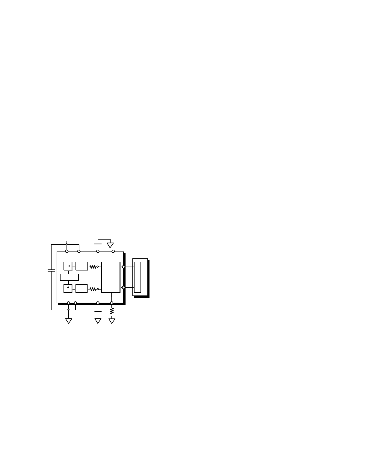
of t h e s en si ti v e axes ( s ee Figu r e 1 ) .
+2.7V TO 5.25V
C
DEMOD
DEMOD
X
DD
R
FILT
32kΩ
R
FILT
32kΩ
Y
FILT
VDDV
X SENSOR
C
DC
OSCILLATOR
Y SENSOR
X
FILT
ADXL202
MODULATOR
C
Y
DUTY
CYCLE
(DCM)
T2COM
SELF TEST
R
SET
X OUT
Y OUT
C
O
U
P
N
T
E
R
Figure 1. ADXL202 Block Diagram
Currently automotive security systems use
shock/vibration sensors to detect collision
or forced intrusion into the car. Typically, these
sensors are based on magneto-inductive sensing.
Sensors of this type generally have adequate
sensitivity, but fall short in other areas. Often
a fair am ount of signal conditi oning and trim ming
is required between the shock sensor and
microcontroller due to variations in magnetic
material and Hall effect sensor sensitivity
and their frequency response is fairly
unpredictable due to inconsistency in mounting.
In addition such sensors have no response
to gravity-induced acceleration, so they are
incapable of sensing inclination (a static
acceleration). Tilt sensing is the most di rect way
of detecting if a vehicle is being jacked up, about
to be towed, or being loaded onto a flatbed truck.
Some of the most common methods of car theft
today.
The ADXL202 is a true accelerometer, easily
capable of shock/vibration sensing with virtually
no external signal conditioning ci rcuit ry. Since the
ADXL202 is also sensitive to static (gravitat ional)
acceleration, tilt sensing is also possible. Tilt
sensing requires a very low noise floor which
usually necessitates restricting the bandwidth of
the accelerometer, while shock/vibration sensing
requires wide bandwidth. These conflicting
requirements may be met using clever design
techniques.
PRINCIPLE OF O PERATIO N
The ADXL202 is set up to acquire acceleration from
0 to 200 Hz (the maximum frequency of interest).
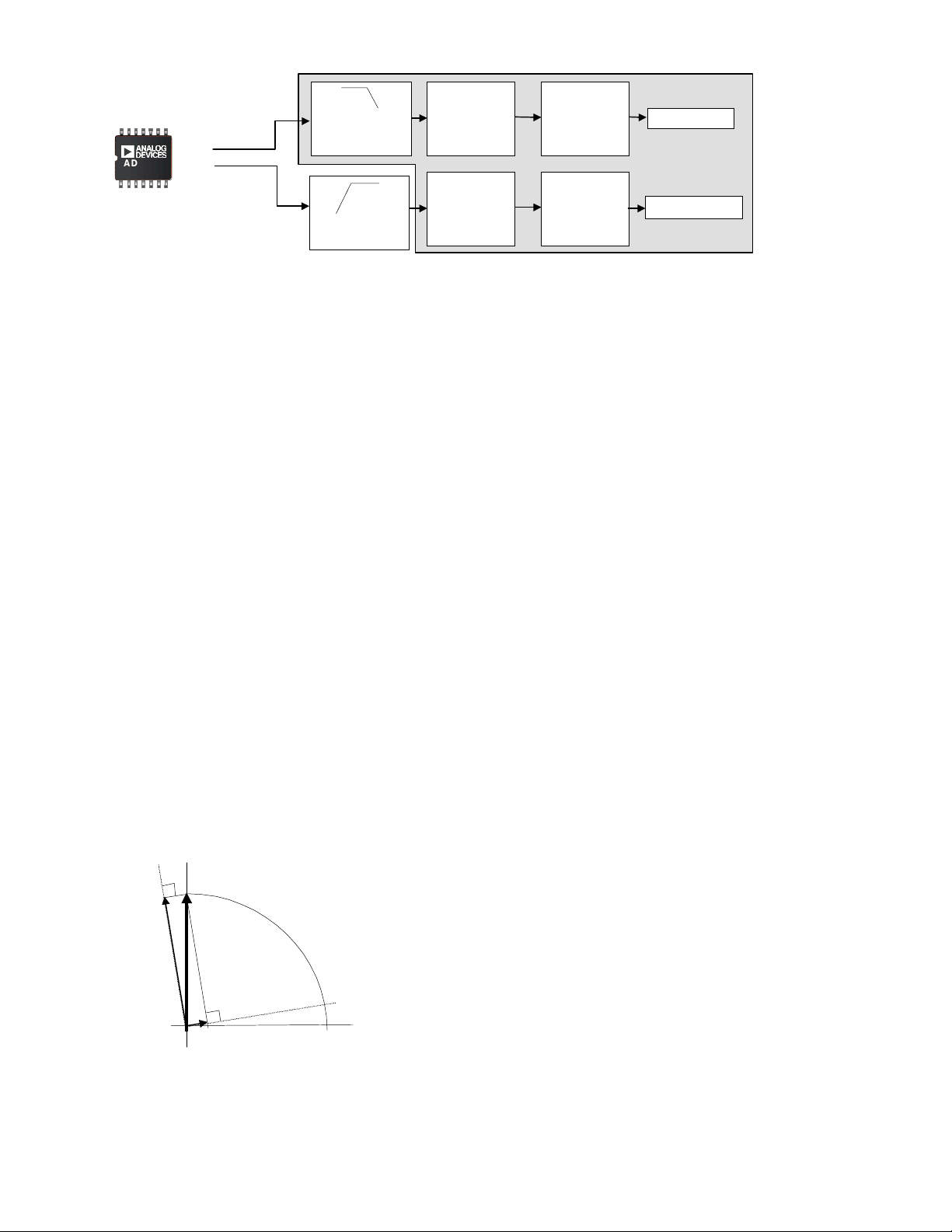
Figure 2 shows a block diagram of the system. The
accelerometer’s output is fed into two filters; a low
pass filter with a cor ner frequency at 12.5 Hz used to
lower the noise floor sufficiently for accurate tilt
sensing, and a band pass filter t o m i nim i ze the noise
in the shock/vibration pass band of int erest. The l ow
pass filtered (tilt ) output then goes to a differentiator
(described in the Tilt Sensing section) where the
determination is made as to whether the
accelerometer actually sensed tilt or some other
event such as noise or temperature drift. Then an
auto-zero block performs f urther signal processing to
reject temperature drift. The band pass filtered
output goes to an integrator (described in the
8/27/98 Rev. A
Page 2
ADXL202
200 Hz Low
Pass Filtered
Digital Output
12.5 Hz L ow P ass
Filter (Samples
Averaging)
Differentiator
Auto-Zero
Recalibration
Tilt Alarm
Low Cost
Analog Output
10 Hz High Pass
Analog Filter
Figure 2. Shock and Tilt Sensing Using the ADXL202
Shock Sensing section) that m easures vibrational
energy over a small period of time (40 ms).
A decision as to whether or not to set off the
alarm may then be made by the microcontroller.
Most of these tasks are most easily im plemented
in the digital domain and require very little
computati onal power.
Since the two measurements (shock/vibrati on and
tilt) are basically exclusive and only share
a common sensor, their respective signal
processing tasks will be described separately.
TILT SENSING
FUNDAMENTALS
The alarm system must detect a change in tilt
slow enough to be the result of the vehicle being
towed or jacked up, but must be immune
to temperature changes and movement due
to passing vehicles or wind. Note that the
ADXL202 is most sensitive to tilt when its
sensitive axes are perpendicular to the force of
gravity, i. e., parallel to t he earth’s surface. Figure
3 shows that the change in projection of a 1
gravity-induced acceleration vector on the axis of
sensitivity of the accelerometer will be more
significant if the axis is tilted 10 degrees from the
horizontal than if it is tilted by the same amount
from the vertical.
Axis of
Sensitivity
1 g
Axis of
Sensitivity
Figure 3. Tilt Sensitivity
Analog to
Digital
Converter
g
Integrator
Shock Alarm
However, the car may not always be level when
the alarm is activated, and while the zero
offset can be recalibrated for any initial
inclination, effectively the farther from the
horizontal the axes of sensitivity are, the less
sensitive the system will be to tilt (see ADXL202
datasheet, page 9). In most cases, this should
not be of great concern, since the sensitivi ty only
g
declines by about 2.5 m
per degree of tilt when
inclination goes from zero (horizontal) to thirty
degrees of tilt. Nevertheless, installation
guidelines should recommend that the tilt sensing
module containi ng the accelerometer be mounted
such that the axes of sensitivity be as level as
possible.
IMPLEMENTATION
In general we are interested in knowing if
the inclination of the car has changed more than
±5 degrees from it’s inclination when initially
parked. When the car is turned off, a
measurement of the car’s inclination is made.
If the car’s inclinat ion is changed by more than ±5
degrees, an alarm is tri ggered. Alternatively, the
rate of change of tilt may be evaluated and if
its absolute value is above 0.2 degrees per
second for several seconds the alarm may be
triggered.
Each technique has certain advantages. The
former algori thm is better at false alarm r ejection
due to jostling of the car, while the rate of change
algorithm may be set up to react more quickly.
Algorithms using a combination of both
techniques may be used as well. It is left
to the reader to decide which technique is best
for their application. While all of the concepts
presented here are valid for both algorithms,
for consistency this application note will describe
the former (absolut e incli nation) algor ithm .
For the purpose of the following discussion,
we will assume a less than perfect tilt sensitivity
g
for the accelerometer of 15 m
or 75 m
g
for 5 degrees. The ADXL202 will be
per degree of tilt ,
set up to have a bandwidth of 200 Hz so that
vibration may be detected. A 200 Hz bandwidth
will result in a noise floor of:
g
Page 3

g
Noise = 500 µ
Noise = 8.5 m
or 34 m
peak to rms ratio of 4:1), well within our 75 m
requirement. For reliability purposes, we would
like to have a noise floor about 10 times lower
than this, or around 8 m
a car takes at least a few seconds, we are free
to narrow the bandwidth to lower the noise floor.
An analog or digital low pass filter may be used,
but since low pass filteri ng in the digital domain i s
very simple, it is the preferred method. By
taking the average of 16 samples we reduce the
effective bandwidth to 12.5 Hz (200 Hz/16
samples). The resulting noise performance is
approximately 8.7 m
to our target.
Lowering the noise floor even further, by taking up
to 128 samples for example, would result i n about
3 m
to easily detect the 15 m
resulting from a change in tilt of less than a
degree.
The t ypi cal zero
ADXL202 is 2 m
tilt alarm could be as low as 15 m
conceivable that temperature drift alone would
cause a false alarm (a car parked overnight
could easily experience more than 7.5 °C
in ambient temperature change). Therefore we
will include a differentiator to reject temperature
drift.
In the event of the car being jacked up or lifted for
towing, we would expect the rate of change in tilt
to be faster than five degrees or 75 m
(or 1.25 m
acceleration is measured it is compared to the
previous reading. If the change is less than 1.25
mg per second we know that the change in
accelerometer output is due to temperature drift.
We can now add an auto-zero block that adjusts
our “zero g” reference (that is the static
acceleration sensed when the car was initially
parked) to compensate for zero
temperature.
SHOCK SENSING
Generally for automotive shock/vibration sensing
we are interested in signals between 10 and 200
Hz. Since the response of the ADXL202 extends
from DC to 5 kHz, a band pass filter will have
to be added to remove out of band signals. This
band pass filter is most easily implemented in
the analog domain (Figure 4 shows a simple 10
Hz high pass filter). When coupled with the 200
g
peak-to-peak of noise (using a peak-to-
g
peak-to-peak of noise, which would allow us
√Hz x (√200 x 1.5) rms
g
rms
g
. Since towing
g
peak-to-peak, close enough
g
of static acceleration
g
drift due to temperature for the
g
/°C. Since our trigger point for a
g
, it is
g
per minute
g
per second). Each time the
g
drift due to
Hz low pass filter (from Xfilt and Yfilt on
the ADXL202), a 10 to 200 Hz bandpass filter is
realized.
g
0.15 µF
100 kΩ
Figure 4. 10 Hz High Pass Filter
Whi le analog bandpass fi ltering i s very sim pl e and
requires no software overhead from the
microcontroller, it does necessitate having an
analog to digit al converter. Today, even low cost
microcontrollers can commonly be found,
integrating an A to D converter on board.
Bandpass filtering in the digital domain may be
more effective, but may require a more powerful
processor than one normally finds in automobile
security systems. There are several methods for
implementing band pass filters in the digital
domain. Specific recommendations will not be
given here since processor selection will influence
what method will be most efficient.
Whether a digital or analog bandpass filter is
used, the Nyquist criteria for signal sampling
must be satisfi ed. That is that we must sampl e at
at least twice the maximum frequency of int erest.
Sampling at 400 Hz (for our 200 Hz pass band)
gives us one sample every 2.5 ms. Our very
simple software integrator will take the sum of the
absolute value of 16 samples and evaluate i f there
is suffici ent energy in that 40 ms period of tim e to
warrant setting off the alarm (i. e. is the sum of 16
samples greater than some set point). It is
assumed that no events will be missed in 40 ms.
DESIGN TRADE-O FFS
The ADXL202 has digital (Pulse W idt h Modulated)
g
as well as analog (312 mV/
either output may be used. Using the PWM
interface for tilt sensing is recommended for two
reasons:
1. We are interested in very small acceleration
signals (on the order of 3 m
correspond to approximately .94 mV.
Probably not resolvable by the on board A to
D converter of any microcontr oller likely to be
used in this applicat ion. The resoluti on of the
pulse width modulator of the ADXL202 is
around 14 bits. Sufficient for resolution of 3
g
acceleration signals.
m
) outputs. In theory,
g
). This would
Page 4

2. All signal processing will be done in the digital
domain.
An analog interface for the shock/vi bration sensor
is recommended since, as previously mentioned,
bandpass filtering in the digital domain may be
beyond the capability of many microcontrollers.
In addition using the PWM interface to acquire
200 Hz bandwidth requires that the PWM
frequency be at least 4 Khz. 10 bit resolution
implies that the microcontroller have a timer
resolution of approximately 250 ns. Once again,
probably beyond the capability of most
microcontrollers.
 Loading...