

5B Series 8 Channel Backplane
FEATURES
Mix and Match 5B Series I/O Module Capability
Factory Mutual (FM) Approved
Approved for Use in Class I, Division2, Groups A, B, C, and D
Locations.
CE Certified: EMC Directive in Heavy Industrial Applications
1500 V rms Channel/Channel and Input/Output Isolation
Four Backplanes and Three Mounting card Options
8- Channels
o
-25
C to +85oC Temperature Range
Single Threaded Insert for module Hold Down
APPLICATIONS
Industrial Signal Conditioning
Industrial Signal Isolation
Industrial Signal Filtering
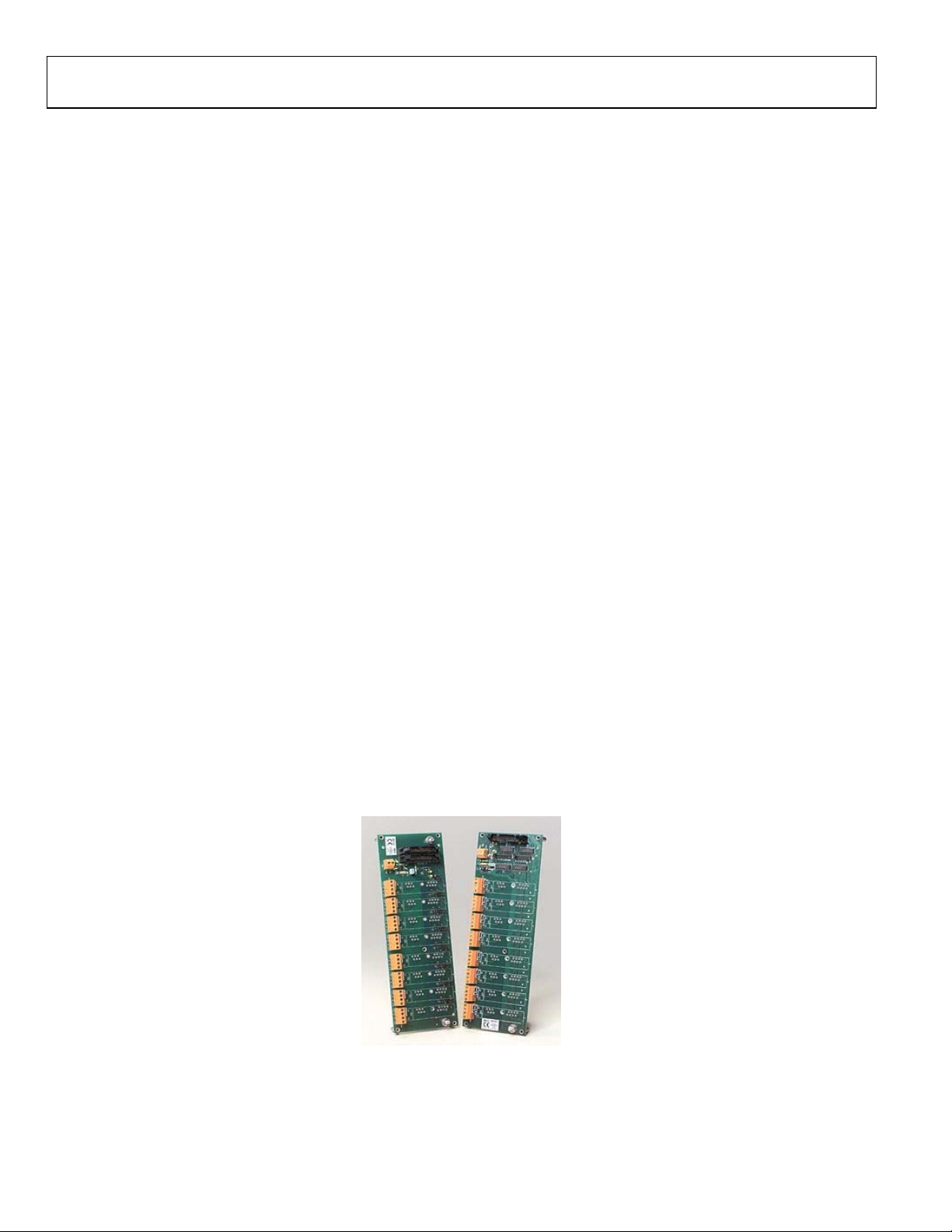
PRODUCT OVERVIEW
To address diverse applications, the 5B Series includes a family
of backplanes and mounting cards which provide a complete
signal conditioning solution. The 8-channel backplanes (models
5B08 and 5B08-MUX) can be mounted in a 19” x 3.5” panel
space, providing different system configuration options.
5B08 / 5B08-MUX
FUNCTIONAL BLOCK DIAGRAM
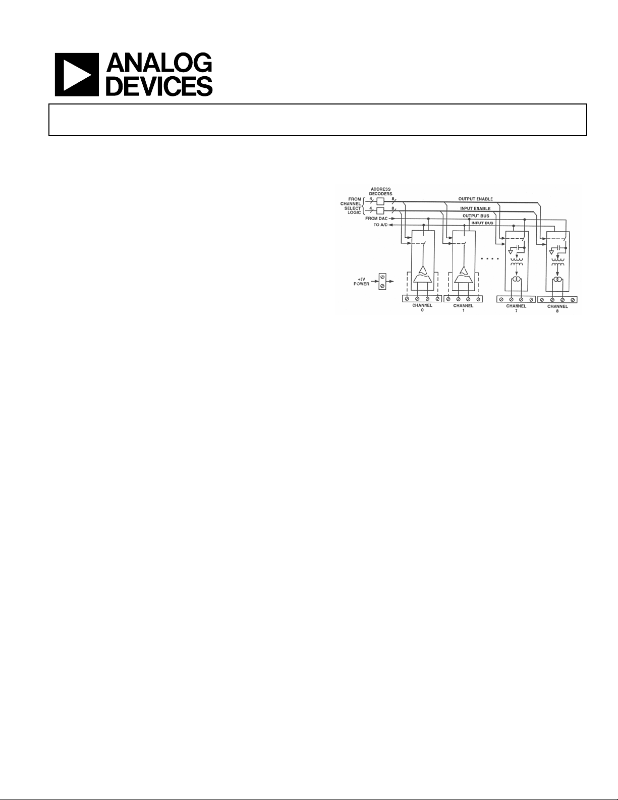
Figure 1 5B08 MUX Functional Block Diagram
This backplane provides four screw terminals per channel for
all field connections. These connections satisfy all transducer
inputs, process current outputs and provide transducer
excitation when necessary. A cold junction temperature sensor
(model AC1361) sensor is also supplied on each channel to
accommodate thermocouple input modules. A pair of pin
sockets permits installation of the AC1362 current sensing
resistor used with the 5B32 current input module on all 8channel backplanes, a 26-pin system interface connector
provides high level I/O for all channels. All 5B Series backplanes
and sockets require a regulated +5VDC external power source.
Rev. 0
Information furnished by Analog Devices is believed to be accurate and reliable.
However, no responsibility is assumed by Analog Devices for its use, nor for any
infringements of patents or other rights of third parties that may result from its use.
Specifications subject to change without notice. No license is granted by implication
or otherwise under any patent or patent rights of Analog Devices. Trademarks and
registered trademarks are the property of their respective companies.
One Technology Way, P.O. Box 9106, Norwood, MA 02062-9106, U.S.A.
Tel: 781.329.4700
Fax: 781.326.8703 © 2005 Analog Devices, Inc. All rights reserved.
www.analog.com
GENERAL DESCRIPTION
Model 5B08 System Connectors – Signal connections between
the 5B08 and the associated measurement and control system
are made with two identical 26-pin connectors (P1 & P2),
similar to the 16-channel model 5B01 backplane. Reference to
these connectors is electrically identical and may be useful if a
5B08 is used for both analog input and analog output and the
data acquisition system has separate input or output connectors.
The I/O connectors provide a signal path for each channel and,
in addition, a number of grounding pins are available to provide
inter-channel shield conductors in the ribbon cable. In some
cases, discussed below, the ground conductors will not provide
an accurate signal reference, so a SENSE pin is also provided in
the connectors. Several jumper and component options on the
5B08 provide optimum ground connections for various
applications.
Model 5B08 Output Channel Selection – To Configure Model
5B08 I/O for different system needs, on-board jumpers are
provided. A family of eight 3-pin jumpers, j8 through J15, allows
the user to assign the 5B08 I/O to either the upper eight I/O
pins (CH0-CH7) or the lower eight I/O pins (CH8-CH15). This
capability allows two 8-channel 5B08 backplanes to be used in a
16 channel configuration, with all I/O assigned to the 16 unique
I/O pins, CH0 – CH15.
Model 5B08 Inter-channel Jumpers – The 5B08 offers the user
the ability to easily connect the voltage output of any 5B Series
input module directly to the voltage input of an adjacent output
module (e.g., Model 5B39) by placing a jumper over two pins J1,
J2, J3, J4, J5, J6, J7. This feature can be used to provide an
isolated current output form an isolated input module. This
results in both isolated voltage and isolated current outputs
from a single sensor input signal.
5B08 / 5B08-MUX
MODEL 5B08-MUX Backplane – The 5B08-MUX
incorporates input and output buses that take advantage of the
internal series output switches in the 5B Series input modules as
well as the track-and-hold circuit in the output modules.
Designers integrating the 5B08-MUX into a measurement and
control system do not need external multiplexers and can use a
single digital-to-analog converter to serve numerous output
channels. Digital outputs from the host data acquisition system
are used to address the 5B Series modules and designate inputs
and outputs. Only one analog input, one analog output and a
number of digital outputs are required to address up to 64
analog input/output channels using eight 5B08-MUX
backplanes.
Model 5B08-MUX Address Jumpers – 5B08-MUX backplane
can hold eight 5B Series modules in any combination of inputs
or outputs. Address decoders on the backplane determine which
module is read (input type) or driver (output type). Separate
decoders are provided for inputs and outputs. To permit system
expansion, up to eight 5B08-MUX backplanes can be daisychained on the system I/O ribbon cable for a total of 64
channels. Jumpers on each backplane (labeled J1 – J9 and J10 –
J18) determine the block of eight addresses assigned to each
backplane. Input (read) and output (write) addressing are
completely independent; in all cases, Jumpers J1-J9 control
inputs and J10-J18 control outputs. Independent addressing
might be used, for example, to update output modules without
interrupting the monitoring of input modules.
Figure 2
Rev. 0 | Page 2 of 8

5B08 / 5B08-MUX Specifications
(typical @ +25°C and Vs =+5 V dc Power)
Description Model 5B08 Model 5B08-MUX
Number of Channels
ISOLATION
Input-to-Output Continuous
Channel-to-Channel Continuous
MECHANICAL DIMENSIONS – with modules
WEIGHT
MOUNTING STANDOFFS
COLD JUNCTION TEMPERATURE SENSORS
Number provided on backplane
Type
Initial Accuracy @ +25oC
Accuracy +5oC to +45oC
SYSTEM I/O CONNECTOR
Number
Type
ADDRESS ENABLE INPUTS
Max Logic “0”
Min Logic “1”
Max Logic “1”
POWER SUPPLY OPTIONS
Voltage; Operating
Voltage; Max Safe Limit – with modules
Current – without modules
Fuse; (F1)
Environmental
Temperature Range
Rated Performance
Operating
Storage
Relative Humidity, 24 hours
8 8
1500 V rms, Maximum
1500 V rms, Maximum
3.5” x 10.0” x 3.2”
(88.9 mm x 240 mm x 81.3 mm)
7 oz. (200 g) 7 oz. (200 g)
5 5
8
Model AC1361
+0.25oC (+0.75oC, maximum)
+0.5oC (+0.0125oC/oC)
2, 26-pin
Amp 746290-6
N/A
N/A
N/A
+5 VDC +5%
+6.0 VDC Max.
13mA
4 Amp Littelfuse © Type 252 004
-25°C to +85°C
-40°C to +85°C
-40°C to +85°C
0 to 95% @ +60°C noncondensing
5B08 / 5B08-MUX
1500 V rms, Maximum
1500 V rms, Maximum
3.5” x 10.0” x 3.2”
(88.9 mm x 240 mm x 81.3 mm)
8
Model AC1361
+0.25oC (+0.75oC, maximum)
+0.5oC (+0.0125oC/oC)
1, 26-pin
Amp 746290-6
+0.8 V
+2.0 V
+7.0 V
+5 VDC +5%
+6.0 VDC Max.
40mA
4 Amp Litttlefuse © Type 252 004
-25°C to +85°C
-40°C to +85°C
-40°C to +85°C
0 to 95% @ +60°C noncondensing
Rev. 0 | Page 3 of 8

PIN CONFIGURATION AND FUNCTIONAL DESCRIPTION (5B08)
Table 1. Pin Function Descriptions—
Pin No. Description
1 CHANNEL 0
2 CHANNEL 8
3 COMMON
4 CHANNEL 9
5 CHANNEL 1
6 COMMON
7 CHANNEL 2
8 CHANNEL 10
9 COMMON
10 CHANNEL 11
11 CHANNEL 3
12 COMMON
13 CHANNEL 4
14 CHANNEL 12
15 COMMON
16 CHANNEL 13
17 CHANNEL 5
18 COMMON
19 CHANNEL 6
Figure 3 5B08 System I/O Connector
20 CHANNEL 14
21 COMMON
22 CHANNEL 15
23 CHANNEL 7
24 COMMON
25 SENSE 25
26 NO CONNECTION
5B08 / 5B08-MUX
ESD CAUTION
ESD (electrostatic discharge) sensitive device. Electrostatic charges as high as 4000 V readily accumulate on the human
body and test equipment and can discharge without detection. Although this product features proprietary ESD
protection circuitry, permanent damage may occur on devices subjected to high energy electrostatic discharges.
Therefore, proper ESD precautions are recommended to avoid performance degradation or loss of functionality.
Rev. 0 | Page 4 of 8

PIN CONFIGURATION AND FUNCTIONAL DESCRIPTION (5B08-MUX)
Table 2. Pin Function Descriptions—
Pin No. Description
1 V READ
2 I/O COM
3 V WRITE
4 SNS LO
5 I/O COM
6 I/O COM
7 READ (INPUT) ADDR LSB
8 READ (INPUT) ADDR BIT 2
9 READ (INPUT) ADDR BIT 3
10 READ (INPUT) ADDR BIT 4
11 READ (INPUT) ADDR BIT 5
12 READ (INPUT) ADDR MSB
13 READ (OUTPUT) ADDR LSB
14 READ (OUTPUT) ADDR BIT 2
15 READ (OUTPUT) ADDR BIT 3
16 READ (OUTPUT) ADDR BIT 4
17 READ (OUTPUT) ADDR BIT 5
18 READ (OUTPUT) ADDR MSB
19 READ ENB (0)
20 WRITE ENB (0)
Figure 4 5B08-MUX System I/O Connector
21 NO CONNECTION
22 RESERVED
23 NO CONNECTION
24 NO CONNECTION
25 D COM
26 D COM
5B08 / 5B08-MUX
ESD CAUTION
ESD (electrostatic discharge) sensitive device. Electrostatic charges as high as 4000 V readily accumulate on the human
body and test equipment and can discharge without detection. Although this product features proprietary ESD
protection circuitry, permanent damage may occur on devices subjected to high energy electrostatic discharges.
Therefore, proper ESD precautions are recommended to avoid performance degradation or loss of functionality.
Rev. 0 | Page 5 of 8

OUTLINE DIMENSIONS
5B08 / 5B08-MUX
Figure 5 Outline Dimensions
Rev. 0 | Page 6 of 8

NOTES
5B08 / 5B08-MUX
Rev. 0 | Page 7 of 8

NOTES
5B08 / 5B08-MUX
© 2005 Analog Devices, Inc. All rights reserved. Trademarks and
registered trademarks are the property of their respective companies.
D05413-0-2/05(0)
Rev. 0 | Page 8 of 8
 Loading...