

Page 1
AN-753
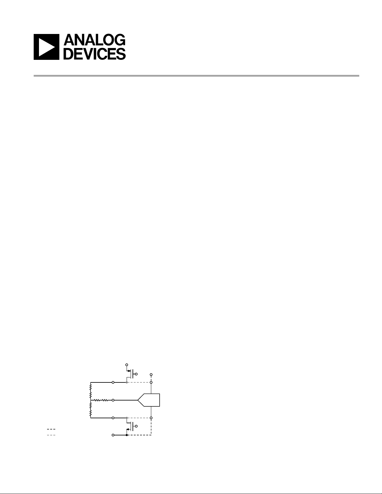
ADC
INPUT
(VIA MUX)
TOUCH
SCREEN
V
REF
V
CC
X+
REF+
SINGLE-ENDED METHOD
RATIOMETRIC METHOD
REF–
Y+
Y–
GND
APPLICATION NOTE
One Technology Way • P.O. Box 9106 • Norwood, MA 02062-9106 • Tel: 781/329-4700 • Fax: 781/326-8703 • www.analog.com
Conguring the AD7877
by Susan Pratt
INTRODUCTION
The AD7877 touch screen controller is a 12- bit successive approximation ADC with a synchronous serial
interface and low on resis tance switches for driving
touch screens. The AD7877 features direc t bat ter y
measurement on two inputs, temperature and touchpressure measurement.
The AD7877 has many user-programmable conversion
controls, including variable acquisition time, rst conversion delay, and averaging. It is ideal for battery-powered
systems, such as personal digital assistants, smar t
phones, and other portable equipment with resistive
touch screens.
The AD7877 requires conguration via the on- board
registers to fully utilize its features. This application
note goes through the conguration process step by
step, and explains how to congure the device for your
application.
SINGLE-ENDED OR RATIOMETRIC MEASUREMENT
The main task of any touch screen controller is to take
accurate measurements from the touch screen. On the
AD7877, there are two measurement methods available:
single- ended or ratiometric. The difference between the
two methods is in the ADC reference voltage. In single ended mode, the ADC is referenced to ground and to
V
. (V
REF
an external reference). For the differential measurement,
the ADC is referenced to the screen excitation voltage.
REV. 0
can be either the internal reference voltage or
REF
Figure 1. Measurement Methods
The advantage of using the single -ended method is that
the touch screen does not need to be powered except
during signal acquisition. Signal acquisition takes only
a portion of the total conversion time. This method can
result in signicant power savings in the system, as the
screen itself can draw more than 1 mA while powered.
This method also has some disadvantages. Voltage
drops across the internal switches cause errors in the
measurement, as they reduce the apparent excitation
voltage across the screen. In addition, this method
can only be used when VCC is close to V
the ADC is saturated (when VCC > V
REF
the full range of the ADC is not used (VCC < V
, otherwise
REF
), or conversely,
). The
REF
single - ended method is particularly suited for batteryoperated systems where power is at a premium. It is only
recommended for applications that use the nger as an
input device, and therefore do not need high accuracy
measurements.
Using the touch screen excitation voltage as the ADC
referen ce gives a ratiometric measurement of the
input signal. This method is more accurate than the
single - ended method because voltage drops across the
internal switches do not have any effect on the measured
results. However, the screen needs to be powered at all
times in order to provide the ADC with its reference. For
applications such as handwriting recognition, where the
measured touch screen position must be accurate, the
ratiometric method is recommended.
AVERAGING
The signals measured from the touch screen can be
noisy. To minimize low level noise, the AD7877 can
automatically perform averaging on the measured input
signals. The AD7877 can be programmed to perform one,
four, eight, or sixteen consecutive measurements on the
same channel, and write the averaged result to the result
register. The more averages the part performs, the longer
each measurement takes. When choosing the amount of
averaging in the system, the time available for conversions needs to be taken into account. The amount of
averaging required will depend on the noise factors in
the specic system, but in general, at least four averages
are recommended for each measurement.
Page 2

AN-753
–3–
AN-753
FIRST CONVERSION DELAY = 8.19ms
FIRST CONVERSION DELAY = 1.024ms
FIRST CONVERSION DELAY = 500ns
REV. 0
STOPACQ
In most applications, the touch screen is placed directly
on top of the LCD. Periodic noise from the display can
interfere with the touch screen measurements. As the
LCD horizontal lines are written, noise is generated that
can be coupled onto the touch screen. This specic
type of noise is generally framed by an LCD control
signal related to the horizontal refresh phase. HSYNC
and Vcom are the two typical control signals found on
different types of LCDs. The noise can be framed by the
high or low period of these signals, or it may be worse
at the signal transitions.
If the user sees periodic noise in the system, an analysis
should be performed to determine if the noise is coming
from the LCD, and whether there is a control signal
available that frames the noise. This control signal
should be tied directly to the AD7877 StopAc q pin,
provided the signal level is suitable. Even if the control
signal does not frame all the noise but frames at least
some of it, greater accuracy will be obtained by using
the StopAcq feature.
The StopAcq feature can be used with any signal to
control the acquisition period of the AD7877. Its recommended use is in prevention of noise pickup from the
LCD as described earlier, but that does not preclude its
use for other purposes.
Figure 2 graphically illustrates the ef fect of the rst
conversion delay on the accuracy of the touch screen
results. The correc t first conversion delay value for
the particular touch screen used in this experiment is
1.024 ms. The samples taken from the touch screen using
this value are in green and clearly show that all points
on the touch screen can be measured correctly. Plenty
of samples are gathered all over the screen.
If the rst conversion delay is set too small, then the
range of values read from the screen is severely limited.
In this case, the signal has not had time to settle, so the
input value is being measured while the signal is still
ramping up to its true value. As illustrated by the red
samples, vast areas of the screen will never register as
being touched.
If the rst conversion delay is too large, then not enough
samples are measured to gain suf cient information
from the screen. The black samples illustrate this. While
positions from the full screen area can be measured, the
time between samples is too great. If the touched position was to move quickly, not enough samples would be
taken to track these changes. Applications such as writing on the screen would be impossible with too large a
rst conversion delay.
FIRST CONVERSION DELAY
The nature of the touch screen measurement process
means that voltages are being switched on and off the
touch screen pins in rapid sequence. To get both X and
Y positions, voltage needs to be switched across rst the
X then the Y layer, while the Y+ or X+ input is switched
to the ADC. Once the voltages are switched, the input
signal will require a settling time before it reaches its
true value. Taking a measurement before the signal is
settled gives an erroneous result.
The AD7877 can be programmed to add an automatic
delay before each touch screen measurement commences. The delay should be long enough to allow the
input signal to settle. The AD7877 rst conversion delay
can be 500 ns, 128 µs, 1.024 ms, or 8.19 ms. The user
should calculate the settling time of the input signal and
then choose a rst conversion delay that is at least as
long. Note that the choice of rst conversion delay will
add to the total conversion time. The rst conversion
delay happens automatically before the rst conversion
is performed on the AD7877, before each touch screen
positional measurement, and after the nal conversion
in a sequence.
Figure 2. Effect of First Conversion Delay on
Touch Screen Results
–2–
REV. 0
Page 3

ACQUISITION TIME
11 0
AUX
3
AUX
2
AUX
1
Z
2
X+Y+
NOT
USED
Z
1
TEMP
2
TEMP
1
BAT
2
BAT
1
The AD7877 has sample-and - hold circuitry to control
acquisition of the input signal. One of the most com mon errors made when integrating a touch screen into
an application is miscalculation of the acquisition time
required to capture the input signal correctly. The acqui sition time depends on a number of factors, including the
source impedance and capacitance of the input signal,
and the input RC of the controller itself.
The addition of a low-pass lter to the touch screen pins
has a large ef fect on the acquisition time. While a lter
can help reduce noise, it also increases the acquisition
time required to successfully measure the input signal.
The user must remember to add any resistances or
capacitances from these lters to their acquisition time
calculation. For the AD7877, the following equation
can be used to get a rough idea of the acquisition time
required for an input signal for 12-bit accuracy.
t
~= (RIN + 100 ) (CIN + 30 pF) 10
ACQ
where:
RIN is the source impedance.
100 is the input impedance of the AD7877.
CIN is the input capacitance of the source.
30 pF is the input capacitance of the AD7877.
The AD7877 allows the user to choose from acquisition
times of 2 µs, 4 µs, 8 µs, or 16 µs by writing to an on-chip
register. The user calculates the required acquisition
time for the circuit, and picks the most suitable acquisition time from the options available on the AD7877.
USING THE SEQUENCER AND TIMER
To minimize host intervention when the AD7877 is run ning, the part has an on - board sequencer and timer.
These can be programmed by the user to ensure the
AD7877 per f orms conversions automatically at set
intervals, or when the screen is touched. The sequencer
is used to choose whic h conversions occur in the
sequence. This allows the AD7877 to run in a standalone
mode, where the only host intervention required af ter
setup is to read the result registers. The on- chip timer
does not have to be used, but it can be set to expire every
512 µs, 1.024 ms, or 8.19 ms.
There are two sequence registers on the AD7877. One
of the sequenc e regis ter s contains the conver sion
sequence for use when the screen is touched, known as
master mode. The second sequence register contains
the conversion sequence for use in slave mode. Each bit
in the registers corresponds to a conversion on one of
the AD7877‘s input channels. To add a conversion to the
sequence, the corresponding bit in the sequence register
is set. To remove the conversion from the sequence, the
bit is cleared.
AN-753
Figure 3. Sequence Register Bits
To trigger a conversion sequence every time the screen
is touched, the AD7877 should be put into master
mode by setting Bit 0 and Bit 1 of Control Register 1
to Control Register 11’b. Once the sequence of conversions is nished and the results are in the registers, the
DAV interrupt will signal to the host that new data is
available. The sequence of conversions in the master
mode sequence register will be repeated automatically
every time the screen is touched. If the screen remains
touched for a long time, for example, if someone is
writing on the screen, then the timer can be used to
trigger the sequence. However, when the screen is not
being touched, the timer cannot trigger the conversion sequence. Master mode is useful for a number of
applications. It can automatically gather positional data
while a user writes on the screen. It requires little host
intervention, as the AD7877 will only interrupt the host
once new data is written to the registers when the screen
is touched.
There is a second sequence register on the AD7877 for
use in slave mode. The AD7877 can be placed into slave
mode by setting Bit 0 and Bit 1 of the control register
to 10’b. The conversion sequence in the slave mode
sequence register is performed once when the part is put
into slave mode. The sequence is repeated automatically
when a timer event occurs, irrespective of whether the
screen is touched or not. If the timer is not set, then the
user needs to write to Control Register 1 again to trigger
the slave mode sequence.
REV. 0
–3–
Page 4

AN05206–0–1/05(0)
© 2005 Analog Devices, Inc. All rights reserved. Trademarks and registered trademarks are the property of their respective owners.
–4–
 Loading...