

Page 1

AN-603
a
One Technology Way • P.O. Box 9106 • Norwood, MA 02062-9106 • Tel: 781/329-4700 • Fax: 781/326-8703 • www.analog.com
APPLICATION NOTE
A Compact Algorithm Using the ADXL202
Duty Cycle Output
by Harvey Weinberg
Introduction
There are many applications where high accuracy measurement of acceleration is less important than having a
simple and compact software algorithm. This application
note outlines a decode algorithm that measures only the
pulsewidth (T1) output of the ADXL202 and translates it to
degrees of tilt. In this algorithm, the period (T2) is not
measured, and no binary division is used.
In PIC assembly code, a total of 199 bytes of program
memory and 18 bytes of data memory are used. Even
more efficient memory (particularly data memory) usage
can be had with further optimization. A flow chart of the
algorithm is included so that the user may modify it or
port it to any 4- or 8-bit microcontroller with little effort.
Using this technique, we simplify tilt angle calculation
down to a simple 1 s per degree relationship. Any
modulo-2 factor of 500 s (e.g., 1000 s, 2000 s, and so
on) may be used as required.
Error Sources
Scale error is the most significant error source encountered when using this algorithm. We assume that the
overall scale factor is 16 m
multiple) in this algorithm, but the actual scale factor
may be anything from 10% per
results in a ±8∞ error over ±40∞ of tilt. Another obvious
error source is having the wrong value for T2. A 1% error
in T2 will result in a 1% error in tilt angle resolution.
These errors may be eliminated by adding a trim to T2.
g
per s (or some modulo-2
g
to 15% per g. This
A discussion of error sources inherent in this method of
measurement is also included.
Principle of Operation
The ADXL202 outputs a pulsewidth modulated (PWM)
signal proportional to acceleration. Assuming that the
scale factor is fixed at 12.5
acceleration T T g duty cycle= (( 1/ 2) – (0 )) 12.5 %
Where T1 is the pulsewidth and T2 is the period of the
ADXL202’s PWM output.
In a temperature stable environment, we can assume
that the average value of
we can rearrange the formula for
acceleration T T at g T= (( 1– 2 0 ) 2) 12.5%
Over a range of ±35∞ of tilt, each degree of tilt is very
close to 16 m
can take advantage of very easy modulo-2 division to
minimize computational requirements when calculating
tilt angle. For example:
g
. By choosing particular values of T2, we
Ts
2 500
=
gs s
1 (500 ) (12.5%) 62.5
=¥=
sg s mg
1(162.5 ) 16
==
mm
%
per g:
T
2 does not change. Therefore
acceleration
m
mm
as:
Scale factor error and
together by adjusting
some modulo-2 multiple) relationship is maintained.
This is expressed by the following equation:
T scalefactor21 0016=¥(( ) ( . ))
So, for example, for a scale factor of 10%:
T2 s=¥=1 ((0.10) (0.016)) 625 m
Adjusting T2 to 625 s in this case would eliminate the
errors due to scale factor and
Since scale factor variation may result in such large
errors, trimming T2 by adding a potentiometer in series
with R
trim may be omitted in applications where one is interested only in changes in tilt angle, and errors due to
scale factor and T2 inaccuracy can be tolerated.
T2 may drift over temperature by as much as a few percent. This is very difficult to compensate for using this
type of algorithm. It is suggested that another algorithm
be used in situations where this is problematic.
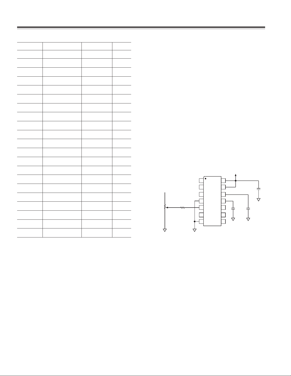
as shown in Figure 1 is recommended. This
SET
T
2 error may be trimmed out
T
2 such that the 16 mg per s (or
T
2 accuracy.
REV. 0
© Analog Devices, Inc., 2002
Page 2
AN-603
Table I. Tilt Angle vs. Error
Tilt Angle
g
Generated T1 in s Error
00.000 0 0
20.034 2 0
40.069 4 0
60.104 6 0
80.139 8 0
10 0.173 10 0
12 0.207 12 0
14 0.241 15 1
16 0.275 17 1
18 0.309 19 1
20 0.342 21 1
22 0.374 23 1
24 0.406 25 1
26 0.438 27 1
The assumption that over ±35∞ of tilt, each degree of tilt is
very close to 16 m
one degree of tilt is 17.45 m
14.38 m
g
. While at first glance this looks like a large
g
, is of course an approximation. At 1∞,
g
; at 35∞, one degree
of tilt is
source of error, it turns out that it only works out to ±1∞ of
error over a ±40∞ range of tilt as shown in Table I.
There is normally a certain amount of “jitter” in T2.
Since the duty cycle does not change as a result of this
jitter, T1 changes proportionally with T2. This error
source in minimized in the 0
g
calibration routine by taking the average value of T1 over 16 readings. This is not
done in normal sampling to allow wider bandwidth
operation. If wide bandwidth is not a concern, the user
may wish to modify the algorithm to include a similar
averaging scheme in normal sampling to minimize this
error due to T2 jitter.
The final source of error is from aliasing in the duty cycle
modulator itself. As discussed in the ADXL202 data
sheet, the analog bandwidth should be limited to
1/10 the duty cycle modulator frequency. So for a T2
period of 1000 s, the analog bandwidth should be
100 Hz or less.
V
DD
28 0.469 29 1
30 0.500 31 1
32 0.529 33 1
34 0.559 34 0
36 0.587 36 0
38 0.615 38 0
40 0.642 40 0
20k⍀
50k⍀
Y
FILT
Figure 1. Circuit for Trimming T2
C
DC
X
FILT
–2–
REV. 0
Page 3

Program Listing and Flow Chart
;***********************************************************************
;
;********** 202-T1.ASM ***************************************
;********** REVISION: 0 ***************************************
;
; RELEASED: SEPT. 16, 1998
; REVISED:
;
; THIS SOFTWARE USES T1 MEASUREMENTS ONLY TO DETERMINE ACCELERATION
; EXPERIENCED BY THE ADXL202. THE OUTPUT IS A 1-BYTE HEXADECIMAL
; NUMBER PER AXIS OF RANGE 00 TO FF. THE MOST SIGNIFICANT BIT IS A SIGN
; BIT. A 1 IN THE MSB INDICATES POSITIVE ACCELERATION. A 0 IN THE MSB
AN-603
; INDICATES NEGATIVE ACCELERATION. TO MAKE THE SOFTWARE AS COMPACT AS
; POSSIBLE, T2 IS ASSUMED TO HAVE A FIXED VALUE. VARIATION FROM THIS
; VALUE WILL RESULT IN ERROR. IT IS ALSO ASSUMED THAT THE FACTOR OF
; IS FIXED AS SHOWN IN THE TABLE BELOW. SO FOR TILT MEASUREMENT OVER
; ⫾40 DEGREES, THIS ROUTINE IS ACCURATE TO APPROXIMATELY ONE DEGREE.
; SINCE THE OUTPUT IS A 1-BYTE NUMBER, RESPONSE IS LIMITED TO ⫾ 1 g.
;
; T2 (IN mSEC)
; 1000 0.008 2
; 2000 0.004 4
; 4000 0.002 8
; 8000 0.001 16
;
;======================================================================
g
/T1 (HOW MANY g FOR 1 mSEC) mSEC/DEGREE
g
/T1
LIST P=16C62A ;SPECIFY PROCESSOR
;======================================================================
REV. 0
–3–
Page 4

AN-603
;======================================================================
;
; REGISTER DEFINITIONS
;
;======================================================================
W EQU H'0000'
F EQU H'0001'
;----- REGISTER FILES--------------------------------------------------
INDF EQU H'0000'
TMR0 EQU H'0001'
PCL EQU H'0002'
STATUS EQU H'0003'
FSR EQU H'0004'
PORTA EQU H'0005'
PORTB EQU H'0006'
PORTC EQU H'0007'
PCLATH EQU H'000A'
INTCON EQU H'000B'
PIR1 EQU H'000C'
TMR1L EQU H'000E'
TMR1H EQU H'000F'
T1CON EQU H'0010'
TMR2 EQU H'0011'
T2CON EQU H'0012'
SSPBUF EQU H'0013'
SSPCON EQU H'0014'
CCPR1L EQU H'0015'
CCPR1H EQU H'0016'
CCP1CON EQU H'0017'
–4–
REV. 0
Page 5

OPTION_REG EQU H'0081'
TRISA EQU H'0085'
TRISB EQU H'0086'
TRISC EQU H'0087'
PIE1 EQU H'008C'
PCON EQU H'008E'
PR2 EQU H'0092'
SSPADD EQU H'0093'
SSPSTAT EQU H'0094'
;----- STATUS BITS ----------------------------------------------------
AN-603
IRP EQU H'0007'
RP1 EQU H'0006'
RP0 EQU H'0005'
NOT_TO EQU H'0004'
NOT_PD EQU H'0003'
Z EQU H'0002'
DC EQU H'0001'
C EQU H'0000'
;----- INTCON BITS ----------------------------------------------------
GIE EQU H'0007'
PEIE EQU H'0006'
T0IE EQU H'0005'
INTE EQU H'0004'
RBIE EQU H'0003'
T0IF EQU H'0002'
INTF EQU H'0001'
REV. 0
–5–
Page 6

AN-603
RBIF EQU H'0000'
;----- PIR1 BITS ------------------------------------------------------
SSPIF EQU H'0003'
CCP1IF EQU H'0002'
TMR2IF EQU H'0001'
TMR1IF EQU H'0000'
;----- T1CON BITS -----------------------------------------------------
T1CKPS1 EQU H'0005'
T1CKPS0 EQU H'0004'
T1OSCEN EQU H'0003'
NOT_T1SYNC EQU H'0002'
T1INSYNC EQU H'0002' ;BACKWARD COMPATIBILITY
TMR1CS EQU H'0001'
TMR1ON EQU H'0000'
;----- T2CON BITS -----------------------------------------------------
TOUTPS3 EQU H'0006'
TOUTPS2 EQU H'0005'
TOUTPS1 EQU H'0004'
TOUTPS0 EQU H'0003'
TMR2ON EQU H'0002'
T2CKPS1 EQU H'0001'
T2CKPS0 EQU H'0000'
;----- SSPCON BITS ----------------------------------------------------
–6–
REV. 0
Page 7

WCOL EQU H'0007'
SSPOV EQU H'0006'
SSPEN EQU H'0005'
CKP EQU H'0004'
SSPM3 EQU H'0003'
SSPM2 EQU H'0002'
SSPM1 EQU H'0001'
SSPM0 EQU H'0000'
;----- CCP1CON BITS ---------------------------------------------------
CCP1X EQU H'0005'
AN-603
CCP1Y EQU H'0004'
CCP1M3 EQU H'0003'
CCP1M2 EQU H'0002'
CCP1M1 EQU H'0001'
CCP1M0 EQU H'0000'
;----- OPTION BITS ----------------------------------------------------
NOT_RBPU EQU H'0007'
INTEDG EQU H'0006'
T0CS EQU H'0005'
T0SE EQU H'0004'
PSA EQU H'0003'
PS2 EQU H'0002'
PS1 EQU H'0001'
PS0 EQU H'0000'
;----- PIE1 BITS ------------------------------------------------------
REV. 0
–7–
Page 8

AN-603
SSPIE EQU H'0003'
CCP1IE EQU H'0002'
TMR2IE EQU H'0001'
TMR1IE EQU H'0000'
;----- PCON BITS ------------------------------------------------------
NOT_POR EQU H'0001'
;----- SSPSTAT BITS ---------------------------------------------------
D EQU H'0005'
I2C_DATA EQU H'0005'
NOT_A EQU H'0005'
NOT_ADDRESS EQU H'0005'
D_A EQU H'0005'
DATA_ADDRESS EQU H'0005'
P EQU H'0004'
I2C_STOP EQU H'0004'
S EQU H'0003'
I2C_START EQU H'0003'
R EQU H'0002'
I2C_READ EQU H'0002'
NOT_W EQU H'0002'
NOT_WRITE EQU H'0002'
R_W EQU H'0002'
READ_WRITE EQU H'0002'
UA EQU H'0001'
BF EQU H'0000'
;======================================================================
–8–
REV. 0
Page 9

;
; RAM DEFINITION
;
;======================================================================
__MAXRAM H'BF'
__BADRAM H'08'-H'09', H'0D', H'18'-H'1F'
__BADRAM H'88'-H'89', H'8D', H'8F'-H'91',H'95'-H'9F'
;======================================================================
;
; RAM EQUATES
AN-603
;
;======================================================================
T1X_1 EQU 20
T1X_0 EQU 21
ARGL EQU 22
ARGH EQU 23
ACCHI EQU 24
ACCLO EQU 25
T1Y_1 EQU 26
T1Y_0 EQU 27
T1XCAL_2 EQU 28
T1XCAL_1 EQU 29
T1XCAL_0 EQU 2A
T1YCAL_2 EQU 2B
T1YCAL_1 EQU 2C
T1YCAL_0 EQU 2D
X_ACCEL EQU 2E
Y_ACCEL EQU 2F
T1CAL_COUNT EQU 30
REV. 0
–9–
Page 10

AN-603
ROTCNT EQU 31
;======================================================================
;
; CONFIGURATION BITS
;
;======================================================================
_CP_ALL EQU H'3F8F'
_CP_75 EQU H'3F9F'
_CP_50 EQU H'3FAF'
_CP_OFF EQU H'3FBF'
_PWRTE_ON EQU H'3FBF'
_PWRTE_OFF EQU H'3FB7'
_WDT_ON EQU H'3FBF'
_WDT_OFF EQU H'3FBB'
_LP_OSC EQU H'3FBC'
_XT_OSC EQU H'3FBD'
_HS_OSC EQU H'3FBE'
_RC_OSC EQU H'3FBF'
;======================================================================
;***** PROGRAM ******
;***** MAIN PROGRAM *****
;***** RESET ROUTINE *****
ORG 0000
GOTO PROG_START ;GO TO START OF PROGRAM
GOTO PROG_START
GOTO PROG_START ;THESE COMMANDS ARE HERE TO
–10–
REV. 0
Page 11

GOTO PROG_START ;KICK THE PROGRAM COUNTER PAST
RETURN ;THE INTERRUPT VECTORS IN CASE
RETURN ;OF A GLITCH
PROG_START
CLRF PORTA
CLRF PORTB
CLRF PORTC
BSF STATUS,5 ;RAM PAGE 1
MOVLW B'11111111' ;SET UP THE I/O PORTS
MOVWF TRISA ;PORT A, ALL INPUTS
MOVLW B'11111111'
AN-603
MOVWF TRISB ;PORT B, ALL INPUTS
MOVLW B'11111111'
MOVWF TRISC ;PORT C, ALL INPUTS
BCF STATUS,5 ;SET RAM PAGE 0
MAIN_LOOP
CALL CHECK_CAL ;CHECK IF CALIBRATION ROUTINE
CALL READ_T1 ;READ ACCELERATION
MOVF T1X_1,0 ;CHECK ACCELERATION POLARITY
SUBWF T1XCAL_1,0
BTFSS STATUS,C
GOTO ACCX_GT_ZX
;SHOULD BE PERFORMED
REV. 0
BTFSS STATUS,Z
GOTO ACCX_LT_ZX
MOVF T1X_0,0
SUBWF T1XCAL_0,0
BTFSS STATUS,C
–11–
Page 12

AN-603
GOTO ACCX_GT_ZX
MOVF T1XCAL_0,0
MOVWF ACCLO
MOVF T1XCAL_1,0
MOVWF ACCHI
MOVF T1X_0,0
MOVWF ARGL
MOVF T1X_1,0
MOVWF ARGH
CALL SUB_16X16
BCF STATUS,C ;DIVIDE BY 2 (1 SHIFT) IF T2=1000mS
ACCX_LT_ZX ;X ACCELERATION IS NEGATIVE
RRF ACCHI,1 ;DIVIDE BY 4 (2 SHIFTS) IF T2=2000mS
RRF ACCLO,0 ;DIVIDE BY 8 (3 SHIFTS) IF T2=4000mS
MOVWF X_ACCEL
BCF X_ACCEL,7 ;CLEAR THE SIGN BIT AS ACCEL IS -
GOTO DO_Y_AXIS
ACCX_GT_ZX ;X ACCELERATION IS POSITIVE
MOVF T1X_0,0
MOVWF ACCLO
MOVF T1X_1,0
MOVWF ACCHI
MOVF T1XCAL_0,0
MOVWF ARGL
MOVF T1XCAL_1,0
MOVWF ARGH
CALL SUB_16X16
BCF STATUS,C ;DIVIDE BY 2 (1 SHIFT) IF T2=1000mS
RRF ACCHI,1 ;DIVIDE BY 4 (2 SHIFTS) IF T2=2000mS
RRF ACCLO,0 ;DIVIDE BY 8 (3 SHIFTS) IF T2=4000mS
MOVWF X_ACCEL
–12–
REV. 0
Page 13

BSF X_ACCEL,7 ;SET THE SIGN BIT AS ACCEL IS +
DO_Y_AXIS
MOVF T1Y_1,0 ;CHECK FOR ACCELERATION POLARITY
SUBWF T1YCAL_1,0
BTFS S STATUS,C
GOTO ACCY_GT_ZY
BTFS S STATUS,Z
GOTO ACCY_LT_ZY
MOVF T1Y_0
SUBWF T1YCAL_0,0
BTFSS STATUS,C
AN-603
GOTO ACCY_GT_ZY
ACCY_LT_ZY ;Y ACCELERATION IS NEGATIVE
MOVF T1YCAL_0,0
MOVWF ACCLO
MOVF T1YCAL_1,0
MOVWF ACCHI
MOVF T1Y_0,0
MOVWF ARGL
MOVF T1Y_1,0
MOVWF ARGH
CALL SUB_16X16
BCF STATUS,C ;DIVIDE BY 2 (1 SHIFT) IF T2=1000mS
RRF ACCHI,1 ;DIVIDE BY 4 (2 SHIFTS) IF T2=2000mS
RRF ACCLO,0 ;DIVIDE BY 8 (3 SHIFTS) IF T2=4000mS
REV. 0
MOVWF Y_ACCEL
BCF Y_ACCEL,7 ;CLEAR THE SIGN BIT AS ACCEL IS -
GOTO MAIN_LOOP
ACCY_GT_ZY ;Y ACCELERATION IS POSITIVE
MOVF T1Y_0,0
–13–
Page 14

AN-603
MOVWF ACCLO
MOVF T1Y_1,0
MOVWF ACCHI
MOVF T1YCAL_0,0
MOVWF ARGL
MOVF T1YCAL_1,0
MOVWF ARGH
CALL SUB_16X16
BCF STATUS,C ;DIVIDE BY 2 (1 SHIFT) IF T2=1000mS
RRF ACCHI,1 ;DIVIDE BY 4 (2 SHIFTS) IF T2=2000mS
RRF ACCLO,0 ;DIVIDE BY 8 (3 SHIFTS) IF T2=4000mS
MOVWF Y_ACCEL
BSF Y_ACCEL,7 ;SET THE SIGN BIT AS ACCEL IS +
GOTO MAIN_LOOP
;***** SUBROUTINES *****
;**********************************************************************
CHECK_CAL ;THIS SUBROUTINE READS THE "CAL" PIN (RA4). IF IT
;IS HI, A SIMPLE CALIBRATION ROUTINE IS PERFORMED
;TO MEASURE THE 0
;T1 ARE AVERAGED (BY ADDING TOGETHER AND THEN
;DIVIDING BY 16) TO INCREASE ACCURACY.
BTFSS PORTA,3 ;IS RA4 HI
RETURN ;IF NOT THEN NO CAL ROUTINE
CLRF T1XCAL_2 ;IF YES THEN ACQUIRE CAL DATA
g
VALUE OF T1. SIXTEEN SAMPLES OF
CLRF T1XCAL_1 ;START BY CLEARING ALL
CLRF T1XCAL_0 ;OF THE CALIBRATION REGISTERS
CLRF T1YCAL_2
CLRF T1YCAL_1
CLRF T1YCAL_0
–14–
REV. 0
Page 15

ZCAL_A
AN-603
MOVLW 10 ;SET AVERAGING COUNTER TO 16
MOVWF T1CAL_COUNT
MOVF T1CAL_COUNT,1 ;TEST IF 16 PASSES HAVE OCCURRED BY
BTFSC STATUS,Z ;TESTING IF THE LOOP COUNTER = 0
GOTO ZCAL_B
CALL READ_T1 ;READ T1
MOVF T1X_0,0 ;DO AVERAGING CALCULATIONS OF T1X
ADDWF T1XCAL_0,1
BTFSS STATUS,C ;CHECK IF A CARRY WAS GENERATED
GOTO ZCAL_C
MOVLW 01 ;IF A CARRY WAS GENERATED INCREMENT
ADDWF T1XCAL_1
BTFSC STATUS,C ;CHECK IF A CARRY WAS GENERATED
INCF T1XCAL_2,1
ZCAL_C
MOVF T1X_1,0
ADDWF T1XCAL_1
BTFSC STATUS,C ;CHECK IF A CARRY WAS GENERATED
INCF T1XCAL_2
MOVF T1Y_0,0
ADDWF T1YCAL_0,1 ;DO AVERAGING CALCULATIONS OF T1Y
BTFSS STATUS,C
GOTO ZCAL_D
MOVLW 01
ADDWF T1YCAL_1
ZCAL_D
REV. 0
BTFSC STATUS,C
INCF T1YCAL_2,1
MOVF T1Y_1,0
ADDWF T1YCAL_1
–15–
Page 16

AN-603
BTFSC STATUS,C
INCF T1YCAL_2
DECF T1CAL_COUNT ;DECREMENT LOOP COUNTER
GOTO ZCAL_A ;LOOP
ZCAL_B
MOVLW 04 ;DIVIDE T1CAL BY 16
MOVWF ROTCNT
ZCAL_E
RRF T1XCAL_2,1
RRF T1XCAL_1,1
RRF T1XCAL_0,1
RRF T1YCAL_2,1
RRF T1YCAL_1,1
RRF T1YCAL_0,1
MOVLW 01
SUBWF ROTCNT,1
BTFSS STATUS,Z
GOTO ZCAL_E
RETURN
;**********************************************************************
READ_T1 ;THIS SUBROUTINE ACQUIRES T1X AND T1Y
;T1X IS IN REGISTERS T1X_1,T1X_0
;T1Y IS IN REGISTERS T1Y_1,T1Y_0
CLRF T1CON ;SET TIMER 1 TO ZERO
CLRF TMR1L
EDGE1
EDGE2
CLRF TMR1H
BTFSC PORTB,2 ;WAIT FOR RISING EDGE
GOTO EDGE1
–16–
REV. 0
Page 17

EDGE3
AN-603
BTFSS PORTB,2
GOTO EDGE2
BSF T1CON,TMR1ON ;TURN TIMER 1 ON
NOP ;WAIT 3 mSEC TO DEGLITCH
NOP
NOP
BTFSC PORTB,2 ;LOOK FOR FALLING EDGE
GOTO EDGE3
BCF T1CON,TMR1ON ;STOP TIMER 1 TO READ RELIABLY
MOVFT MR1H,0
MOVWF T1X_1
EDGE4
EDGE5
MOVF TMR1L,0
MOVWF T1X_0
CLRF TMR1L ;CLEAR THE TIMER RESULT REGISTERS
CLRF TMR1H ;IN PREPARATION FOR T1Y CAPTURE
BTFSC PORTB,1 ;LOOK FOR THE RISING EDGE ON
GOTO EDGE4 ;Y CHANNEL
BTFSS PORTB,1
GOTO EDGE5
BSF T1CON,TMR1ON ;TURN TIMER 1 BACK ON AT RISING EDGE
NOP ;WAIT 3 mSEC TO DEGLITCH
NOP
NOP
EDGE6
REV. 0
BTFSC PORTB,1 ;LOOK FOR FALLING EDGE SIGNIFYING
GOTO EDGE6 ;THE END OF T1Y
BCF T1CON,TMR1ON ;STOP TIMER 1 TO READ END OF T1Y
MOVF TMR1H,0
–17–
Page 18

AN-603
MOVWF T1Y_1
MOVF TMR1L,0
MOVWF T1Y_0
RETURN
;**********************************************************************
SUB_16X16 ;THIS SUBROUTINE PERFORMS A 16 BIT BY 16 BIT
;SUBTRACTION.
;(ACCHI,ACCLO)=(ACCHI,ACCLO)-(ARGH,ARGL)
COMF ARGL
INCF ARGL
BTFSC STATUS,2
DECF ARGH
COMF ARGH ;NEGATE ZERO
MOVF ARGL,W ;THEN ADD
ADDWF ACCLO,F
BTFSC STATUS,W
INCF ACCHI
MOVF ARGH,W
ADDWF ACCHI,F
RETURN
;*********************************************************************
END
–18–
REV. 0
Page 19

–19–
Page 20

E03048–0–7/02(0)
–20–
PRINTED IN U.S.A.
 Loading...