


AN-562
a
APPLICATION NOTE
One Technology Way • P.O. Box 9106 • Norwood, MA 02062-9106 • 781/329-4700 • World Wide Web Site: http://www.analog.com
Filter Specification for the Internal Filters of the
ADV7190/ADV7191/ADV7192/ADV7194 Video Encoders
INTRODUCTION
This application note documents the filter specifications
and detailed plots of the internal filters of the ADV7190/
ADV7191, ADV7192 and ADV7194 video encoders.
All the above-mentioned devices provide two luma lowpass filters, two luma notch filters, an extended SSAF™
(Super Sub Alias Filter) luma low-pass filter, a luma CIF
and a luma QCIF filter, five chroma low-pass filters, a
Chroma CIF and a Chroma QCIF filter.
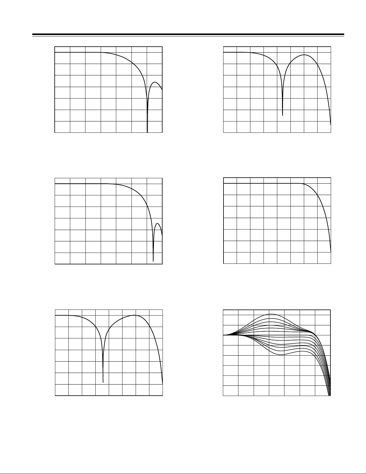
The SSAF filter, as can be seen in Figure 5, provides a
sharp stopband attenuation that enables studio quality
video playback on modern TVs, giving optimal horizontal line resolution.
Additionally, it is possible to change the response of the
SSAF filter in the passband in using the programmable
gain/attenuation feature or sharpness control as can be
seen in Figures 6, 7 and 8. Overall, there are six programmable gain responses (Figure 7) and six programmable
attenuation responses (Figure 8) in the range of –4 dB to
+4 dB available. These responses can be programmed
over the I
The tables on the following pages show the filter specifications for all the filters in 2× oversampling and 4×
oversampling mode.
Figures 1–17 highlight the frequency responses in the
passband and stopband.
Figures 18–31 highlight the different frequency responses
in 2× oversampling and 4× oversampling.
Tables I, II, III, and IV apply to the ADV7190/ADV7191,
ADV7192 and ADV7194 video encoders.
2C®
interface.
Table I. Luminance Internal Filter Specifications (2ⴛ Oversampling)
Passband 3 dB Stopband Stopband
1
Ripple
Filter Type Filter Selection (dB) (MHz) (MHz) (dB)
MR04 MR03 MR02
Low-Pass (NTSC) 0 0 0 0.09 4.158 6.05 –65.7
Low-Pass (PAL) 0 0 1 0.15 4.74 6.41 –81.1
Notch (NTSC) 0 1 0 0.09 2.25/5.0/6.54 8.03 –88
Notch (PAL) 0 1 1 0.095 3.07/5.8/6.24 8.02 –80.5
Extended (SSAF) 1 0 0 0.017 6.37 8.03 –87.4
CIF 1 0 1 0.012 3.0 5.09 –69.2
QCIF 1 1 0 0.118 1.5 3.74 –88.4
NOTES
1
Passband Ripple refers to the maximum fluctuations from the 0 dB response in the passband, measured in dB. The passband is defined to have 0 (Hz) to
fc (Hz) frequency limits for a low-pass filter, 0 (Hz) to f1 (Hz) and f2 (Hz) to infinity for a notch filter, where fc, f1, f2 are the –3 dB points.
2
3 dB bandwidth refers to the –3 dB cutoff frequency.
3
Stopband Cutoff refers to the frequency (MHz) at attenuation point (dB) referred to under Note 4.
4
Stopband Attenuation refers to the attenuation (dB) at the frequency (MHz) referred to under Note 3.
SSAF is a trademark of Analog Devices, Inc.
I2C is a registered trademark of Philips Corporation.
Bandwidth
2
Cutoff
3
Attenuation
REV. 0
4
AN-562
Table II. Chrominance Internal Filter Specifications (2ⴛ Oversampling)
Passband 3 dB Stopband Stopband
Ripple
1
Bandwidth
Filter Type Filter Selection (dB) (MHz) (MHz) (dB)
MR07 MR06 MR05
1.3 MHz Low-Pass 0 0 0 0.087 1.397 2.46 –84
0.65 MHz Low-Pass 0 0 1 Monotonic 0.653 2.41 –78.3
1.0 MHz Low-Pass 0 1 0 Monotonic 1.0 1.89 –66.6
2.0 MHz Low-Pass 0 1 1 0.0438 2.21 3.1 –65
3.0 MHz Low-Pass 1 0 0 Monotonic 3.18 5.33 –84.9
CIF 1 0 1 Monotonic 0.653 2.41 –78.3
QCIF 1 1 0 Monotonic 0.5 1.75 –33.17
Table III. Luminance Internal Filter Specifications (4ⴛ Oversampling)
Passband 3 dB Stopband Stopband
Ripple
1
Bandwidth
Filter Type Filter Selection (dB) (MHz) (MHz) (dB)
MR04 MR03 MR02
Low-Pass (NTSC) 0 0 0 0.16 4.24 6.05 –75.2
Low-Pass (PAL) 0 0 1 0.1 4.81 6.41 –64.6
Notch (NTSC) 0 1 0 0.09 2.27/4.9/6.6 8.03 –87.3
Notch (PAL) 0 1 1 0.1 3.1/5.6/6.4 8.02 –79.7
Extended (SSAF) 1 0 0 0.043 6.45 8.03 –86.6
CIF 1 0 1 0.127 3.02 5.09 –62.6
QCIF 1 1 0 Monotonic 1.5 3.74 –88.2
2
2
Cutoff
Cutoff
3
3
Attenuation
Attenuation
4
4
Table IV. Chrominance Internal Filter Specifications (4ⴛ Oversampling)
Passband 3 dB Stopband Stopband
Ripple
1
Bandwidth
2
Cutoff
3
Attenuation
Filter Type Filter Selection (dB) (MHz) (MHz) (dB)
MR07 MR06 MR05
1.3 MHz Low-Pass 0 0 0 0.09 1.395 2.46 –83.9
0.65 MHz Low-Pass 0 0 1 Monotonic 0.65 2.41 –71.1
1.0 MHz Low-Pass 0 1 0 Monotonic 1.0 1.89 –64.43
2.0 MHz Low-Pass 0 1 1 0.048 2.2 3.1 –65.9
3.0 MHz Low-Pass 1 0 0 Monotonic 3.2 5.3 –84.5
CIF 1 0 1 Monotonic 0.65 2.41 –71.1
QCIF 1 1 0 Monotonic 0.5 1.75 –33.1
NOTES
1
Passband Ripple refers to the maximum fluctuations from the 0 dB response in the passband, measured in dB. The passband is defined to have 0 (Hz) to
fc (Hz) frequency limits for a low-pass filter, 0 (Hz) to f1 (Hz) and f2 (Hz) to infinity for a notch filter, where fc, f1, f2 are the –3 dB points.
2
3 dB bandwidth refers to the –3 dB cutoff frequency.
3
Stopband Cutoff refers to the frequency (MHz) at attenuation point (dB) referred to under Note 4.
4
Stopband Attenuation refers to the attenuation (dB) at the frequency (MHz) referred to under Note 3.
4
–2–
REV. 0
MAGNITUDE – dB
FREQUENCY – MHz
–70
0
71
MAGNITUDE – dB
23456
–10
–30
–40
–50
–60
–20
0
0
8
FREQUENCY – MHz
–70
0
71
MAGNITUDE – dB
23456
–10
–30
–40
–50
–60
–20
0
0
8
AN-562
0
0
–10
–20
–30
–40
–50
–60
–70
0
23456
FREQUENCY – MHz
71
Figure 1. Luma NTSC Low-Pass Filter
(4
MAGNITUDE – dB
–10
–20
–30
–40
–50
–60
–70
×
0
0
0
Oversampling)
23456
FREQUENCY – MHz
71
Figure 2. Luma PAL Low-Pass Filter (4× Oversampling)
Figure 4. Luma PAL Notch Filter (4x Oversampling)
Figure 5. Extended (SSAF) Luma Filter
(4x Oversampling)
0
0
–10
–20
–30
–40
MAGNITUDE – dB
–50
–60
–70
0
23456
FREQUENCY – MHz
8
71
Figure 3. Luma NTSC Notch Filter (4x Oversampling)
Figure 6. Extended (SSAF) Luma Filter
MAGNITUDE – dB
–10
–12
0
4
2
0
–2
–4
–6
–8
0
2345 6
FREQUENCY – MHz
71
(4x Oversampling) with Programmable
Attenuation/Gain in the Passband
REV. 0
–3–

AN-562
5
4
3
2
MAGNITUDE – dB
1
0
–1
0
23456
FREQUENCY – MHz
71
Figure 7. Extended (SSAF) Luma Filter
(4x Oversampling) Zoom In on Programmable
Gain in the Passband
1
0
–1
0
0
–10
–20
–30
–40
MAGNITUDE – dB
–50
–60
–70
0
FREQUENCY – MHz
1.0 1.5 2.0 2.5 3.0
0.5
3.5 4.0
Figure 10. Luma QCIF Filter (4x Oversampling)
0
0
–10
–20
–2
MAGNITUDE – dB
–3
–4
–5
0
23456
FREQUENCY – MHz
71
Figure 8. Extended (SSAF) Luma Filter
(4x Oversampling) Zoom In on Programmable
Attenuation in the Passband
0
0
–10
–20
–30
–40
MAGNITUDE – dB
–50
–60
–30
–40
MAGNITUDE – dB
–50
–60
–70
0
FREQUENCY – MHz
0.4 0.6 0.8 1.0 1.2
0.2
1.4 1.6 1.8 2.0
Figure 11. Chroma 0.65 MHz Low-Pass Filter
0
0
–10
–20
–30
–40
MAGNITUDE – dB
–50
–60
–70
0
1
23456
FREQUENCY – MHz
Figure 9. Luma CIF Filter (4x Oversampling)
–70
0
0.4 0.6 0.8 1.0 1.2
0.2
FREQUENCY – MHz
Figure 12. Chroma 1.0 MHz Low-Pass Filter
(4x Oversampling)
–4–
1.4 1.6 1.8 2.0
REV. 0

AN-562
0
0
–10
–20
–30
–40
MAGNITUDE – dB
–50
–60
–70
0
1.0 1.5 2.0 2.5 3.0
0.5
FREQUENCY – MHz
Figure 13. Chroma 1.3 MHz Low-Pass Filter
(4x Oversampling)
0
0
–10
–20
–30
0
0
–10
–20
–30
–40
MAGNITUDE – dB
–50
–60
–70
0
FREQUENCY – MHz
0.4 0.6 0.8 1.0 1.2
0.2
1.4 1.6 1.8 2.0
Figure 16. Chroma CIF Filter (4x Oversampling)
0
0
–10
–20
–30
–40
MAGNITUDE – dB
–50
–60
–70
0
FREQUENCY – MHz
1.0 1.5 2.0 2.5 3.0
0.5
3.5 4.0
Figure 14. Chroma 2.0 MHz Low Pass Filter
(4x Oversampling)
0
0
–10
–20
–30
–40
MAGNITUDE – dB
–50
–60
–70
0
1
23456
FREQUENCY – MHz
Figure 15. Chroma 3.0 MHz Filter (4x Oversampling)
–40
MAGNITUDE – dB
–50
–60
–70
0
FREQUENCY – MHz
1.0 1.5 2.0 2.5 3.0
0.5
3.5 4.0 4.5 5.0
Figure 17. Chroma QCIF Chroma Filter
(4x Oversampling)
MAGNITUDE – dBMAGNITUDE – dB
–20
–40
–60
–80
–20
–40
–60
–80
0
0
0
0
510152025
510152025
FREQUENCY – MHz
2ⴛ OVERSAMPLING
4ⴛ OVERSAMPLING
Figure 18. Luma NTSC Low-Pass Filter
REV. 0
–5–

AN-562
0
–20
–40
–60
MAGNITUDE – dBMAGNITUDE – dB
–80
–20
–40
–60
–80
0
0
0
510152025
510152025
FREQUENCY – MHz
Figure 19. Luma PAL Low-Pass Filter
0
–20
–40
–60
MAGNITUDE – dBMAGNITUDE – dB
–80
–20
–40
–60
–80
0
0
0
510152025
510152025
FREQUENCY – MHz
Figure 20. Luma NTSC Notch Filter
2ⴛ OVERSAMPLING
4ⴛ OVERSAMPLING
2ⴛ OVERSAMPLING
4ⴛ OVERSAMPLING
MAGNITUDE – dBMAGNITUDE – dB
–20
–40
–60
–80
–20
–40
–60
–80
0
0
0
0
510152025
510152025
FREQUENCY – MHz
2ⴛ OVERSAMPLING
4ⴛ OVERSAMPLING
Figure 22. Extended (SSAF) Luma Filter
MAGNITUDE – dBMAGNITUDE – dB
–20
–40
–60
–80
–20
–40
–60
–80
0
0
0
0
510152025
510152025
FREQUENCY – MHz
2ⴛ OVERSAMPLING
4ⴛ OVERSAMPLING
Figure 23. Luma CIF Filter
0
–20
–40
–60
MAGNITUDE – dBMAGNITUDE – dB
–80
–20
–40
–60
–80
0
0
0
510152025
51015 2025
FREQUENCY – MHz
Figure 21. Luma PAL Notch Filter
2ⴛ OVERSAMPLING
4ⴛ OVERSAMPLING
–6–
MAGNITUDE – dBMAGNITUDE – dB
–20
–40
–60
–80
–20
–40
–60
–80
0
0
0
0
510152025
510152025
FREQUENCY – MHz
2ⴛ OVERSAMPLING
4ⴛ OVERSAMPLING
Figure 24. Luma QCIF Filter
REV. 0

AN-562
0
0
FREQUENCY – MHz
0
MAGNITUDE – dBMAGNITUDE – dB
510152025
510152025
–20
–40
–60
–80
0
–20
–40
–60
–80
2ⴛ OVERSAMPLING
4ⴛ OVERSAMPLING
0
–20
–40
–60
MAGNITUDE – dBMAGNITUDE – dB
–80
–20
–40
–60
–80
0
0
0
510152025
510152025
FREQUENCY – MHz
Figure 25. Chroma 0.65 MHz Filter
0
–20
–40
–60
MAGNITUDE – dBMAGNITUDE – dB
–80
–20
–40
–60
–80
0
0
0
510152025
510152025
FREQUENCY – MHz
Figure 26. Chroma 1.0 MHz Filter
2ⴛ OVERSAMPLING
4ⴛ OVERSAMPLING
2ⴛ OVERSAMPLING
4ⴛ OVERSAMPLING
0
–20
–40
–60
MAGNITUDE – dBMAGNITUDE – dB
–80
–20
–40
–60
–80
0
0
0
510152025
510152025
FREQUENCY – MHz
Figure 28. Chroma 2.0 MHz Filter
0
–20
–40
–60
MAGNITUDE – dBMAGNITUDE – dB
–80
–20
–40
–60
–80
0
0
0
510152025
510152025
FREQUENCY – MHz
Figure 29. Chroma 3.0 MHz Filter
2ⴛ OVERSAMPLING
4ⴛ OVERSAMPLING
2ⴛ OVERSAMPLING
4ⴛ OVERSAMPLING
0
–20
–40
–60
MAGNITUDE – dBMAGNITUDE – dB
–80
0
0
–20
–40
–60
–80
0
510152025
510152025
FREQUENCY – MHz
Figure 27. Chroma 1.3 MHz Filter
REV. 0
2ⴛ OVERSAMPLING
4ⴛ OVERSAMPLING
Figure 30. Chroma CIF Filter
–7–

AN-562
MAGNITUDE – dBMAGNITUDE – dB
–20
–40
–60
–80
–20
–40
–60
–80
0
0
0
0
510152025
510152025
FREQUENCY – MHz
Figure 31. Chroma QCIF Filter
2ⴛ OVERSAMPLING
4ⴛ OVERSAMPLING
E3816–0.5–4/00 (rev. 0)
–8–
PRINTED IN U.S.A.
REV. 0
 Loading...