


AN-550
a
APPLICATION NOTE
One Technology Way • P.O. Box 9106 • Norwood, MA 02062-9106 • 781/329-4700 • World Wide Web Site: http://www.analog.com
Serial Transmission of ADV601 Compressed Video
by David Starr
OVERVIEW
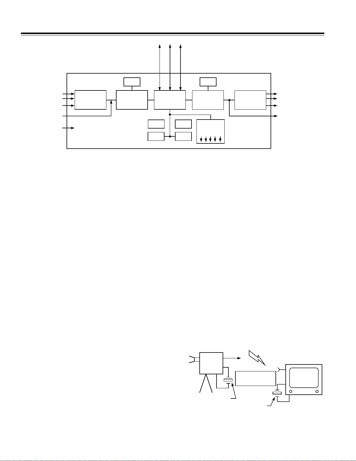
This Application Note describes how to send compressed digital video from one ADV601LC-based Videopipe evaluation board to another Videopipe board. This
enhancement of the Videopipe board function is accomplished merely by replacing the standard Videopipe
firmware with special firmware. No hardware modifications are necessary. The firmware to transmit video is
dubbed TRANLAYR. The firmware to receive is called
RECVLAYR. TRANLAYR and RECVLAYR communicate
video using the ISO 13818 (otherwise known as H.222.0)
transportation protocol over the 8 Megabit/sec serial
ports of the Videopipe boards. The TRANLAYR program
accepts standard analog video from a TV camera or
other source and outputs compressed digital video. The
RECVLAYR program is the inverse, it accepts compressed digital video and outputs standard analog video
to a TV monitor.
This Applications note is for hardware and software designers starting an ADV601 design. Using this note and
the information in any ADV601 family Video Codec data
sheet you can do the following:
Use Videopipe boards as engineering mock-ups on
compressed video projects.
Understand how to select compressed video bit rates.
Understand the theory of operation of TRANLAYR and
RECVLAYR.
Know how to program EPROMs and assemble the
programs.
The design examples in this application note refer to
the ADV601-based Videopipe demonstration board, but
you can apply the techniques used in these examples to
any ADV601-based design. The software source code
and hardware schematics mentioned in this note are
available on the Analog Devices computer products FTP
site, whose Uniform Resource Locator (URL) is:
ftp://ftp.analog.com/pub/dsp/adv601/
Serial Port Electrical Interface and Timing
The serial ports (SPORTS) of the ADV2185 DSP are described at length in the DSP2100 Family User’s Manual,
Chapter 5. These are synchronous serial ports that can
operate at any speed up to 16 Mbps, unlike the usual
RS-232 ports which are limited to perhaps 100 kbps. They
are internal to the chip and thus add no cost to an
ADSP-21xx-based product like Videopipe. The SPORT
input and output pins are connected inside the chip to
ordinary CMOS gates adequate to drive a signal around
a PC board. Long cables will require higher performance
bus drivers and receivers. Circuit designers should be
aware that the SPORT1 I/O pins all have multiple functions. The alternate functions will be unavailable if the
SPORT is in use. For example IRQ0 and Receive Frame
Sync 1 share the same pin. If SPORT 1 is used as a
SPORT, then IRQ0 becomes unavailable. Designers
should conduct a careful “pin inventory” to avoid a “pin
resource conflict” (two functions needing the same pin
at the same time).
Bit Clock and Word Clock
The SPORT uses a bit clock signal to decode the incoming serial data; there are no start or stop bits as in asynchronous serial ports. The “Frame” signal is actually a
word clock delimiting 16 bits on the serial link. Not to be
confused with a video frame, which is 486 lines of video
painted on the CRT. The beginning of each word is
marked by a pulse on the “frame” line. Word length is
programmable over the range 3 to 16 bits. The program
normally uses 16 bits. Eight bits are supported in software. Eight-bit mode can be enabled with some conditional assembly statements.
RAW ANALOG
VIDEO
TV CAMERA
Figure 1. Block Diagram, Serial Video Transmission
COMPRESSED SERIAL
DIGITAL VIDEO
TRANLAYR
VIDEOPIPE
RECVLAYR
VIDEOPIPE
RAW ANALOG
VIDEO
TV MONITOR
AN-550
EZ-ICE JP16
SERIAL PORT
(SPORT) JP17
RS-232 P1
DRAM
Y/C
CVBS
J11
CCIR656
J12
+5V dc
J10
J2
SAA7111
ADV601LC
ADV601LC
VIDEOPIPE
H/W RESET
ADSP-2185
H/W RESET
SRAM PALS
Figure 2. ADV601LC Videopipe Block Diagram
External and Internal Clock(s)
The bit and word clock signals can be programmed as
outputs or inputs to the SPORT. The software makes the
TRANLAYR Videopipe source both bit and word clock
and the receive Videopipe accepts the clock supplied by
the transmitter. This choice was arbitrary (someone has
to source clock and someone has to accept it). Future
versions of the code may autoswitch from internal to external clock at power-up. If an external bit clock is detected the SPORT will be programmed to external clock.
If no external bit clock is detected, the SPORT will be
programmed to source bit clock. Interface to external
equipment (modems, RF transmitters etc.) is often
easier if the Videopipe accepts bit clock from the external equipment. The internal clock is created by dividing
down the processor crystal frequency, 8 MHz in
Videopipe. The Sport0_SclkDiv register is the “divisor.”
Zero yields an 8 MHz bit clock, one gives a 4 MHz bit
clock and so on. See the code in module sport0.dsp.
Bit Clock Automatically Sets the Video Compression Ratio
Bit clock determines how fast the TRANLAYR Videopipe
can send out compressed video. As the bit clock frequency is reduced, the bin width calculator will automatically increase the compression ratio to reduce the
compressed bit rate to a rate the SPORT can handle.
Likewise, should the bit clock frequency increase, the
compression ratio will be reduced to furnish more compressed video bits to send. This is useful when external
bit clock is used. There is no need to alter program code
to match the compression ratio to the SPORT capacity.
Bit and Word Clock Recovery Issues
Usually only one signal, the serial data, is transmitted
over a distance. In this case, the receiver at the far end
has to recover both the bit clock and the word clock
(frame signal) from the incoming serial data. Bit clock
recovery can be done with a phase locked loop (PLL) at
DRAM
Y/C
J8
CVBS
J7
CCIR656
J13
ROMSRAM
ADV601LC
H/W RESET
RESET
UP
FREEZE
PUSH BUTTONS
SELECT
DOWN
ADV7175
the receiver. The PLL needs to adjust the phase of the
local bit clock until the bit clock transitions do not occur
when the data is changing. Word clock (the frame signal) can be recovered by counting bit clocks from some
recognizable marker in the data stream. The Videopipe
serial transmission demo does not address the clock recovery issue. It requires the bit clock and word clock signals to be run between the two Videopipe boards.
Pixel Clock Recovery
Practical systems need to deal with variations of pixel
clock. At the “camera” end of a system, pixels are digitized and TV sync created from a crystal in the camera.
The video is then compressed, transmitted to a distant
receiver, decompressed and played back. In the receiver, TV sync is created from a local crystal in the receiver. The two crystal oscillators (camera and receiver)
will run at slightly different speeds. This causes the receiver to run either slightly faster or slightly slower than
the camera. The receiver finds his compressed video
buffer either running dry or overflowing. The serial
transmission demo merely discards or repeats the occasional video field. A more sophisticated design might
have a variable frequency pixel clock in the receiver and
adjust it to keep the receiver’s pixel clock running at exactly the same speed as the camera’s pixel clock.
COMPRESSED VIDEO
(LESS SYNC) SENT
OVER COMM LINK
27MHz CRYSTAL
IN CAMERA
27MHz CRYSTAL
IN RECEIVER
Figure 3. Pixel Clock Changes from Camera to TV Set
–2–

AN-550
SOFTWARE PROTOCOL (ISO 13818 OR ITU H.222)
Need for Protocol
The receiver of the compressed video could just move
every incoming bit into the decode ADV601 and be done
with it. However, the receiver needs to know where each
video field starts, so he can replay a field should his
compressed video buffer run dry. The receiver also
needs to be able to separate video from audio and maintain lip sync between audio and video. To accomplish
this, the incoming video is broken up into packets. Each
packet has a header that tells the receiver how to handle
the packet contents. This scheme is called a “protocol.”
Many different protocols have been devised over the
years, and many more will be. Rather than invent yet
another new protocol, the existing ISO 13818 protocol
“Generic coding of moving pictures and associated audio information” was selected. Many people call it “The
MPEG 2 Transport Layer” since the ISO title is so unwieldy. The identical text is also published as ITU-T Recommendation H.222.0. The document can be obtained
from ISO or the ITU. The software was coded to comply
with the published standard.
Program Element Streams (PES)
The ISO protocol defines something called a “Program
Element Stream,” or PES for short. Streams are similar
to TV channels. Currently, viewers change “channels”
on analog TV sets to change the program material. They
will change “Program Element Streams” on digital TVs
to accomplish the same task. Several TV programs will
be time division multiplexed over the same digital circuit. The receiver will display only one of the Program
Element Streams, and discard the others. Program Element Streams are broken up into packets, (PES Packets)
and each PES packet has a PES header. In this application, each video PES packet holds a single compressed
video field. Since the compression of each field varies
by about 3%, the PES packets are of variable size, and a
word in the PES header gives the size of the PES packet.
Video goes into one Program Element Stream and audio
goes into another. The receiver routes video to the
ADV601 video codec and audio to the audio codec based
upon PES number (another field in the PES header). The
initial version of the software does video only, but it is
intended to add sound as soon as possible. The audio
packets will contain a field time’s worth (1/30th of a second for NTSC) of audio. Each PES packet has a system
time stamp. The receiver maintains lip sync by comparing the time stamps upon the audio and video PES packets and duplicating or discarding video frames to stay in
sync.
Transport Layer Packets
After the PES streams are formed, a lower level of protocol, the “transport layer,” is placed over the data. The
long variable length PES packets are broken down to fit
into short, fixed-length 188-byte “transport packets.”
Each transport layer packet has a 4-byte header and
184 bytes of “payload.” PES packets are aligned to have
the PES header start at the beginning of a transport layer
packet, and those special packets are marked with a special bit in their header. The last 188-byte transport
packet of a PES packet is only partly full. The transmitter
first forms PES packets, and then puts the PES packets in
to transport layer packets. The receiver reverses this
process, first it strips off the transport layer packet headers and then it strips off the PES packet headers to recover the original compressed video.
TRANSMIT LAYER
Compression Ratio (Bin Width Calculator)
The standard Videopipe bin width calculator uses a
feedback loop to hold the compressed bit rate to whatever the user keys into the program. TRANLAYR uses
the same feedback loop to make the compressed video
bit rate match the bit rate of the serial port. User input
from the push buttons is ignored. Compressed video is
buffered in the video memory. If compressed video
flows into the memory at exactly the same rate that the
serial port takes it away, the level of video in the
memory will stay constant. If the ADV601 does not compress the video enough, the buffer will begin to fill up. If
the video is compressed too much, the buffer will begin
to run dry. The servo feedback loop attempts to hold the
amount of video in the buffer in the buffer constant. In
this way, the compression ratio is automatically adjusted if the serial port speed changes.
Module servo.dsp computes the amount of compressed
video in the buffer by subtracting SPORT_RDPTR from
VRAM_WRPTR. The difference is placed in variable
VIDEO_FULLNESS. These three variables all refer to or
are scaled in 32-bit longwords. The pointers indicate the
number of 32-bit longwords from the beginning of video
memory and their difference is the amount of video
expressed as 32-bit longwords rather than as bytes.
VIDEO_FULLNESS is subtracted from HALF_FULL to
form the servo error signal. To permit the same source
code to function in the standard Videopipe and in TRANLAYR, a conditional assembly statement defines flag
CONSTANT_FULLNESS true to hold the video buffer
level steady, and false to have the bit rate follow the use
input from the control buttons.
Latency
This version of the serial transmission has a good deal
of latency. The video memory is much larger than required for this application (256 Kbytes). The serial port
runs at 8 Mbps, which means each compressed field
should be 16.66 Kilobytes long, and the video memory
can hold 16 compressed fields. Since the servo loop is
holding the video memory half full, there are normally
eight compressed fields in the buffer awaiting transmission. Add to this, a one field time delay going through
the encode ADV601, plus one field time delay for the
decode ADV601 and the overall latency is at least ten
–3–

AN-550
field times or 166 milliseconds. This means the receiver
will be displaying video that lags the input video by almost a sixth of a second. Latency can be substantially
improved by changing the servo.dsp module to hold the
level of video in the buffer to something less than half
full. A new design might use a much smaller buffer.
Autobuffering
To ease the CPU loading, transmission uses SPORT autobuffering. Two output buffers (TX_BUFFER_1 and
TX_BUFFER_2) are used in ping-pong fashion. While the
SPORT is transmitting one buffer, the program is filling
the other buffer. When the SPORT gets to the end of the
active buffer, it asserts the SPORT0 TX interrupt. The
SPORT 0 interrupt service routine then reloads the DAG
I and L register for SPORT0. This routine is located in
module intvec.dsp and is short enough to fit into the
four instruction spaces allocated to each interrupt vector. Interrupt latency is very important. The DAG registers must be refreshed before the SPORT moves on to
the next word. The program has only 32 instruction
times (16 SPORT bit clock times) to reload the DAG registers so this interrupt is always unmasked, even during
other interrupt service routines. The SPORT0 TX interrupt service routine is allowed to “punchthru” all other
interrupt service routines. Context saving (register saving) is difficult. The alternate register set is already in
use, leaving no convenient place to save the DSP registers. Therefore, the SPORT0 TX interrupt service routine
does not use any registers, it moves the new DAG settings directly from DSP data memory to the DAG registers, and flag RDY_FOR_TXPAK by writing the DAG’s M
register into the flag word. The M register must be nonzero at all times otherwise the autobuffering will hang
up. SPORT0 uses DAG 0 (I0,M0&L0) for autobuffering.
These registers must be valid at all times, which means
no other part of the TRANLAYR program may use them
at any time. They must be reserved for SPORT0. Assembler macros (IXMIT_DAG,MXMIT_DAG and LXMIT_DAG)
were defined to make it easier to locate and/or change
which DAG is used by which SPORT.
Transport Layer Packet Processing
Fixed size transport layer packets are created by module
tranpes.dsp. When flag RDY_FOR_TXPAK is set by the
SPORT TX interrupt service routine, the LOAD_PACKET
loop iterates to create enough packets to fill up
TX_BUFFER_1 or _2. The TX_BUFFER’s are larger than
a packet size to prevent running out of packets
before the TRANPES subroutine can again be called.
The LOAD_PACKET loop merely calls subroutine
MAKE_PACKET the proper number of times.
Subroutine MAKE_PACKET is a state machine
with six states: VIDEO_PACK1, VIDEO_PACKN,
VIDEO_PACKLAST, AUDIO_PACK1,AUDIO_PACKN and
AUDIO_PACKLAST. Currently, the AUDIO states are
stubs that output null packets. Future versions of the
program will handle audio from an ADV1819 audio codec. State VIDEO_PACK1 puts a PES header into the
packet payload, fills the rest of the packet with compressed video, and computes the number of transport
packets required to send one compressed field.
N_TXPAK is computed by dividing PES_SIZ by
PAYLOAD_SIZ. State VIDEO_PACKN fills the requested
number of video packets and then goes to state
VIDEO_PACKLAST. The last video packet is usually only
partly full of video and then padded out will FFFF Hex.
The amount of compressed video to place in the last
packet is the remainder from the computation of
N_TXPAK, which is stored in CABOOSE_TXPAK. Then
the state is changed to VIDEO_PACK1. If the program
runs out of compressed video to transmit, it sends a few
null packets by cycling through the AUDIO states.
RECEIVE LAYER
Making the Receive Video Run at the Transmit Rate
Module decisr.dsp takes compressed video out of the
video buffer and displays it. The module has to cope
with two possible catastrophes, running out of compressed video or drowning in compressed video. If the
remote camera’s pixel clock is running slower than the
receiver’s local pixel clock, the receiver will consume
video faster than the camera creates it. In this case, the
receiver simply replays the last video field in his buffer.
On the other hand, if the camera is running faster than
the receiver, the compressed video buffer will fill up and
overflow. In this case, the receiver simply discards a
field without showing it. This problem is inherent in a
compressed video system. No two crystals run at exactly the same frequency. The camera’s crystal controls
the rate at which the camera sends video. The receiver’s
crystal controls the speed that the video is consumed.
Subroutine PLAYBACK_SWITCH_BUF handles the video
speed synchronization. The routine wants the next compressed video field. If there is a next field, all is good.
There might be no next field at all, in which case it
replays the old field. Or, there might be a next field,
but it is not yet full. Particularly daring versions of
PLAYBACK_SWITCH_BUF used to start playing back
such a field hoping the last video of the field might arrive just in time for playback. This strategy (at label
PLOW_AHEAD) sometimes (not always) gives slightly
better performance. If a new field is present, the program should go to LOOK_AHEAD and see if it can skip
some video to prevent buffer overflow.
Autobuffering
The incoming serial data is autobuffered into a single
circular RXBUFFER. Once started, the SPORT 1 register
is never changed, the end of buffer interrupt is turned off
and the SPORT runs around and around the same buffer
in a circular fashion. Subroutine RECVPES computes the
amount of new video in RXBUFFER by subtracting the I
register from RXBUF_PTR. If the amount of new video is
–4–
AN-550
less than WORDS_TRANSPAK (94 words or 188 bytes)
the subroutine exits, otherwise it processes the new
transport layer packet. SPORT receive interrupt latency
is not a problem with this scheme since the receive interrupt is never enabled.
Transport Layer Packet Processing
Subroutine RECVPES is periodically called from the
main loop to take the incoming compressed video out of
RXBUFFER and store it, field by field, into video ram,
just as if it had been captured by the encode ADV601.
The main loop starts at NEXT_RXPAK and runs until
there is no longer a complete transport layer packet
left in RXBUFFER. Variable NBATCH is a “safety first”
count of the number of packets. The comparison of
RX_WORDS2GO with WORDS_TRANSPAK is supposed
to terminate the loop.
The routine has two states, NEED_SYNCBYTE, and
NEED_RXPAK. It starts up in state NEED_SYNCBYTE,
and examines every word in RXBUFFER, looking for the
47 (hex) synchronization code byte. Once found, the routine switches to state NEED_RXPAK and stays there until
it fails to find a transport packet header in the expected
place. This can happen through software error, a transmission error, or data dropout. In this event, the routine goes back to state NEED_SYNCBYTE. There is a
small chance (1 out of 256) that a 47 (hex) sync byte
will occur in the Huffman data. In this case, the
PARSE_TXPAK_HDR routine will return an error when
the bytes following the sync byte do not look like a transport packet header. The error will cause a return to state
NEED_SYNCBYTE.
Subroutine PARSE_TXPAK_HDR checks the continuity
counter in the header against an internally maintained
counter. Any packets that fail to match the continuity
counter are discarded by changing the Program ID number to “NULL PACKET” and returning. Subroutine
STASH knows enough to dump NULL PACKETS on the
floor. Upon a random startup, the continuity counters
will fail to match. Eventually a packet with the
PAYLOAD_START bit set (indicating a PES header in the
packet) will occur, and the internally maintained
counter will be reset to match the counter in the incoming packets.
Flag RXFIRST_BUF stops the processing of the first PES
header. This flag is required for compatibility with the
live video design of the playback code. In live video, the
important system updating and especially the critical
compressed field size variable are not known until the
END of the field (LCODE). In serial video, the size of the
field is known at the beginning of the field. To make use
of the existing code, the size of field (known when the
field starts) is delayed until end of field. The one time
flag RXFIRST_BUF is used to get started.
APPLICATIONS
The Videopipe board could serve as an early engineering mockup or breadboard for a number of products.
Software development could start in the ready-to-run
Videopipe boards while the final product hardware is
under development.
Intelligent Surveillance Camera
The TRANLAYR Videopipe board can serve as the heart
of a digital surveillance camera. The user must do an
interface from the TTL serial signals at JP17 and whatever serial link (POTS, Fiber optic, ISDN, Firewire, USB,
T1) the system uses. The DSP can handle link protocol
such as dialing and answering, and do motion detection.
When motion is detected, the camera could place a call
to the security office to alert them.
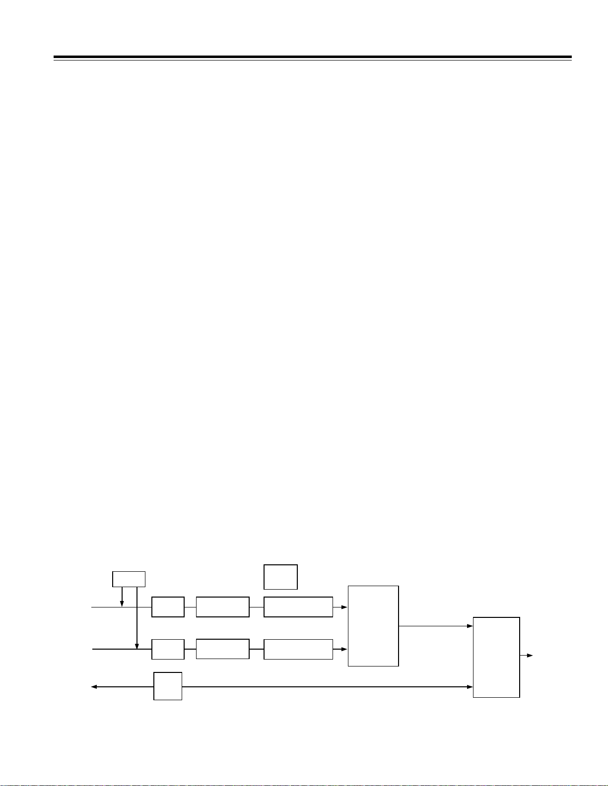
Digital VCR
The digital bit stream from the Videopipe could be
recorded on tape, and played back later. Video quality at
8 Mbps is quite good, on a par with analog VCRs. At
16 Mbps it could be better than Laser Disc and as good
as DVD.
F11216MF MK2
TUNER
YELLOW
VIDEO "RCA"
JACK
IN
RED AND BLUE
STEREO AUDIO
"RCA" JACKS
EXTERNAL
1394
CONNECTOR
VIDEO
A/D
SAA7111
AUDIO
A/D
AD1819
IEEE
1394
I/F
TI OR PHILIPS
VIDEO
BITRATE
CONTROL
VIDEO
COMPRESSION
ADV601LC
AUDIO
COMPRESSION
ADSP-2185 AND DSP SOFTWARE
COMPRESSED PES
VIDEO PACKETIZER
COMPRESSED PES
AUDIO PACKETIZER
33,184 BYTE
PESPACKETS
966 BYTE
PESPACKETS
PES TO
TRANSPORT
STREAM
PACKETIZER
AND
MUX
Figure 4. Capture Mode Logical Block Diagram
–5–
SPORT
@ 14.1 Mbps
188 BYTE MPEG
TRANSPORT PACKETS
INTERFACE
TO
DVHS
TAPE
MEDIA

AN-550
188-BYTE MPEG
TRANSPORT PACKETS
INTERFACE
TO
DVHS
TAPE
MEDIA
@ 14.1 Mbps
33,184 BYTE
PESPACKETS
IEEE
1394
I/F
VIDEO
D/A
ADV7176
AUDIO
D/A
AD1819
SPORT
TRANSPORT
STREAM TO
PES
PACKETIZER
AND
DE-MUX
COMPRESSED PES
VIDEO DEPACKETIZER
966 BYTE
PESPACKETS
COMPRESSED PES
AUDIO DEPACKETIZER
ADSP-2185 AND DSP SOFTWARE
VIDEO
DECOMPRESSION
ADV601LC
AUDIO
DECOMPRESSION
TI OR PHILIPS
Figure 5. Digital Tape Deck Playback Mode Logical Block Diagram
YELLOW
VIDEO "RCA"
JACK
RED AND BLUE
STEREO AUDIO
"RCA" JACKS
EXTERNAL
1394
CONNECTOR
OUT
E3509–2–5/99
CABLE SYSTEM HEAD END
A long haul cable system needs 168 Mbps to move raw
uncompressed video. At 16 Mbps, ten compressed
video channels could move over the same bandwidth, at
broadcast quality.
Video Conferencing System
A Videopipe could serve as full duplex video
conferencing node. One ADV601 decompresses the incoming video, the other compresses the outgoing video.
HOW TO SET UP A SERIAL TRANSMISSION
DEMONSTRATION
Interconnecting Cable
Digi-Key flex cable part number A9BBG-0808F-ND is
short cable to connect the TRANLAYR Videopipe to the
RECVLAYR video pipe. Be sure to put a twist in the cable
so that Pin 1 on one board mates with Pin 7 on the other
board (and Pin 2 with Pin 6 and so on).
How to Burn EPROMs
The TRANLAYR and RECVLAYR programs are posted on
the Internet at ftp.analog.com/pub/dsp/adv601/software.
Source code is mostly common between the two programs. Conditional assembly statements within the
source code cause either the transmit or receive version
of the program to build. The program is written entirely
in ADSP-21xx assembly code and was assembled and
linked with the software tools distributed with the EZ-Kit
LITE DSP evaluation board. Both the Rev 5.1 and the
newer Rev 6 software tools will successfully build the
code.
The TRANLAYR and RECVLAYR directories contain:
1. All the source code (.dsp files).
2. Various “include” files (.h files) needed to assemble
the .dsp files.
3. A makefile (a UNIX-style program build script).
4. A “make” utility (ndmake.zip) to execute the make file.
5. An executable file (.exe) for use with EZ-ICE
®
.
6. A Motorola S-record file (.bnm) for programming
EPROMs.
7. A straight binary compressed splash screen video image (girl.bin).
To make an EPROM, first load the Motorola S-record
(.bnm) file into the PROM programmer at address 0.
Then load the straight binary splash screen video image
into the PROM programmer at address 0C000 Hex and
program the PROM. Any standard 27C040 PROM will
work. If you fail to load the splash screen, or load it at the
wrong address, the program may fail to start. Make one
RECVLAYR PROM and one TRANLAYR PROM.
To build the program from source, first download everything from the ftp site into a clean directory. Make sure
the source files on your hard disk match the ftp site in
both length and date stamp. Mismatches indicate problems. If the files you build from differ from the files on
the ftp site, the executable program will be different, and
probably will not work. Obtain the Analog Devices software tools (asm21, ld21 spl21) from the ADSP-2181EZKit Lite and install them. Obtain a make program.
NDMAKE.zip on the ftp site in the videopipe directory
works well, but any standard make program is acceptable. Microsoft’s NMAKE does not work. Put the make
program in any convenient directory on the DOS path. In
the source code directory , issue the DOS command
“make.” This will assemble all the source modules, link
them, and create the Motorola S-record file.
As a check, compare the new .exe file with the one on
the ftp site. They should be the same, except for about
30 mismatches, caused by a date stamp (date and time
of link) embedded in the .exe file.
PRINTED IN U.S.A.
EZ-ICE is a registered trademark of Analog Devices, Inc.
–6–
 Loading...