

Page 1

AN-393
a
ONE TECHNOLOGY WAY • P.O. BOX 9106
Considerations for Selecting a DSP Processor
(ADSP-2115 vs. TMS320C5x)
INTRODUCTION
Digital signal processing systems demand high performance processors. But high performance cannot be
measured by a processor’s multiplication/accumulation
speed or MIPS (Millions of instructions per second) rating alone. Many times a DSP processor is characterized
mainly by its MIPS rate. Since the instruction of one DSP
device is not necessarily equivalent to that of another
DSP device, a MIPS rating can be misleading. Other
architectural and performance requirements relating to
a DSP processor’s capabilities in areas such as arithmetic, addressing and program sequencing may be
more important. What distinguishes DSPs from other
types of microprocessor and microcontroller architectures is how well they perform in each of the following
areas.
1. Fast and flexible arithmetic
A DSP processor must provide single-cycle computation for multiplication, multiplication with accumulation, arbitrary amounts of shifting, and
standard arithmetic and logical operations. In addition, the arithmetic units should allow for any
sequence of computation so that a given DSP algorithm can be executed without being reformulated.
2. Extended dynamic range on multiplication/
accumulation
Extended sums-of-products are fundamental to DSP
algorithms. Protection against overflow in successive accumulations ensures that no loss of data or
range occurs.
3. Single-cycle fetch of two operands (from either onor off-chip)
Again, in extended sums-of-products calculations, two operands are always needed to feed the
calculation. A processor must be able to sustain
two operand data throughput. Also, flexible addressing capabilities for multiple data memories
is important.
•
APPLICATION NOTE
NORWOOD, MASSACHUSETTS 02062-9106
4. Hardware circular buffering (both on- and off-chip)
A large class of DSP algorithms including most filters require circular buffers. Hardware to handle
address pointer wraparound or modulo addressing
reduces overhead (increasing performance) and
simplifies implementation.
5. Zero overhead looping and branching
DSP algorithms are naturally repetitive and can easily be expressed as loops. Program sequencing that
supports looped code with zero overhead provides
the best performance and the easiest programming
implementation. Likewise, overhead penalties for
conditional program flow are unacceptable in signal
processing applications.
Not all processors currently used for DSP and DSP-like
functions meet these architectural and performance
requirements equally well. This article examines these
considerations for selecting a DSP processor, comparing two 16-bit fixed-point processors, the ADSP-2115
from Analog Devices and the TMS320C5x from Texas
Instruments.
The three sections that follow discuss the five points
above. The arithmetic section discusses items one and
two, the addressing capabilities sections discusses
items three and four and the program sequencing section discusses item five.
Program examples and benchmarks can be found at the
end of this article.
ARITHMETIC CAPABILITIES
The basis of a successful DSP implementation is the
ability to perform fast math. Arithmetic capabilities are
the foundation of DSP performance.
General Purpose Math
One indicator of a good arithmetic architecture is the
ability to perform a wide range of arithmetic computations. These computations should be handled in a
•
617/329-4700
Page 2
BUS
EXCHANGE
PROGRAM MEMORY BUS
24
PMD
INPUT REGS
ALU
OUTPUT REGS
OUTPUT REGS
INPUT REGS
OUTPUT REGS
RESULT BUS
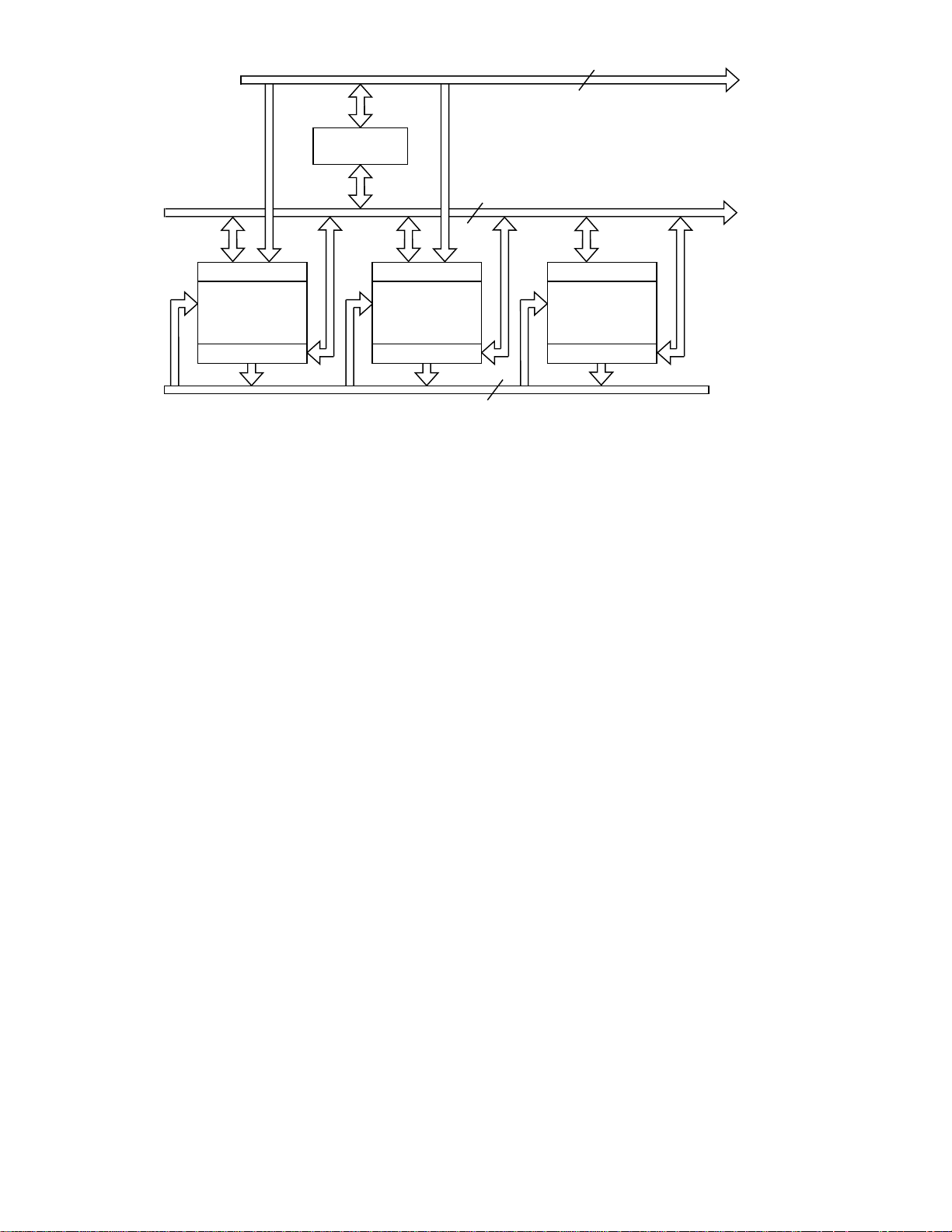
Figure 1. Block Diagram of Arithmetic Section of the ADSP-2115
flexible manner so that the algorithm can be implemented without rearranging the order of the arithmetic
operations or operands. If the arithmetic architecture is
fixed, too special-purpose or limited and the algorithm
must be rearranged, this poses extra work for the DSP
designer or programmer and delays getting a system
running. Algorithm development frequently turns out to
be much of the work of implementing a DSP system. If
an algorithm can be used “as is” with no extra work, the
design can be finished sooner and with less chance of
error.
Arithmetic Architecture
Figure 1 shows a block diagram of the arithmetic section
of the ADSP-2115 while Figure 2 shows that of the
TMS320C50. Both of these devices utilize a modified
Harvard architecture which can feed data operands from
both program memory and data memory to the arithmetic section. Both of these devices work with 16-bit
numbers.
ADSP-2115 Arithmetic Architecture Overview
The ADSP-2115 has three independent computational
units: an ALU, a multiplier/accumulator (MAC), and a
barrel shifter. They are connected (via the Result bus) so
that the output register of any arithmetic unit may be
operated on directly as an input by any other unit. In addition, the ALU and MAC are directly connected to both
the program and data memory buses. Operands for ALU
and MAC operations can come from both memories or
any combination of off-chip memory and other data registers in the processor. All arithmetic operations are register based and a group of registers surrounds each
arithmetic unit. A primary and secondary bank of registers is available to provide for fast context switching. All
arithmetic registers can also be used as general purpose
data registers.
MAC
DMD BUS16
DMD
INPUT REGS
SHIFTER
OUTPUT REGS
16
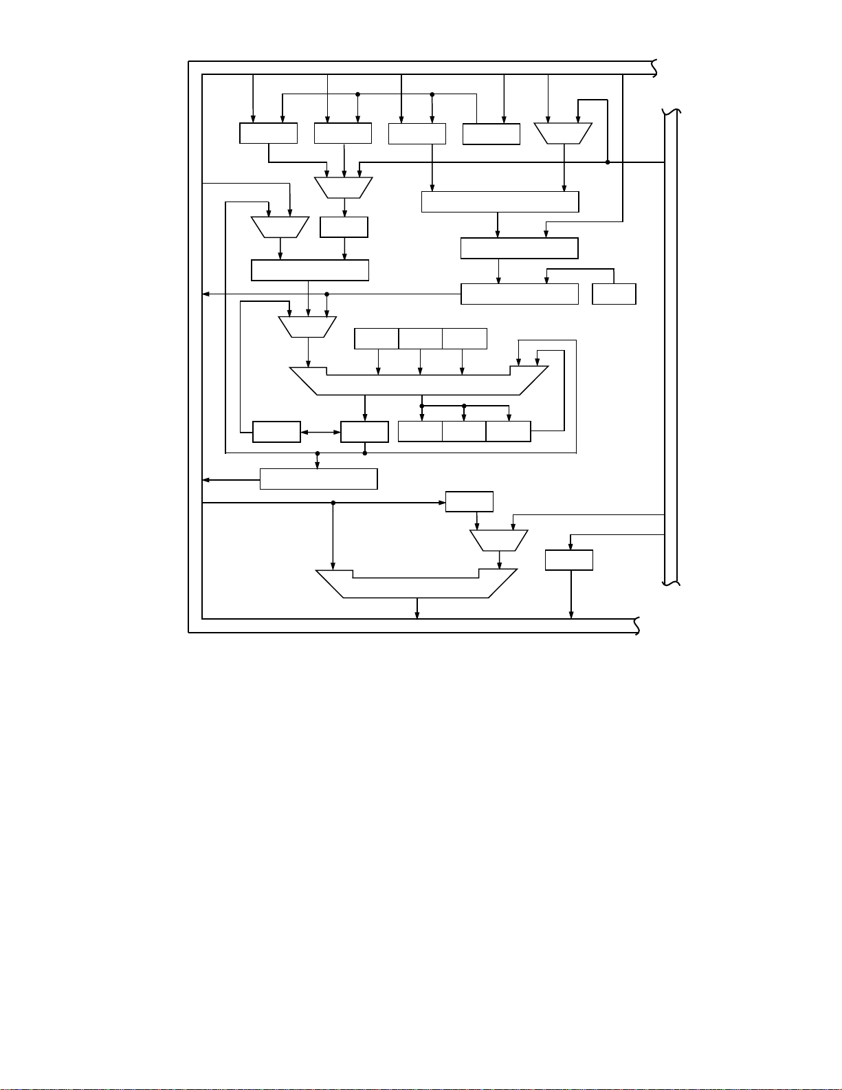
TMS320C5x Arithmetic Architecture Overview
Figure 2 shows the block diagram of the arithmetic section of the TMS320C50. The TMS320C50 contains a multiplier, an ALU, a Parallel Logic Unit (PLU), a 16-bit
scaling shifter and additional shifters at the outputs of
both the accumulator and multiplier. The multiplier has
an input register, TREG0, and an output register, PREG.
The multiplier has direct input connections to both the
program and data bus only for one operand or input.
The ALU has direct access to only the data bus, not the
program bus. Results are always sent to either the data
bus or the accumulator registers. In some cases, the result must first be stored back in data memory before it
can be used as an input for another calculation. Operations such as adding two data values from memory or
multiply/accumulating with a data value can require
multiple cycles.
With the TMS320C50, there is no dedicated multiplier/
accumulator (MAC), which is required in many DSP algorithms. Instead the ALU must be used in conjunction
with the multiplier for MAC operations. This may require
some rearrangement of the algorithm or the temporary
storage of intermediate results in data memory if the algorithm requires MAC operations interleaved with ALU
operations. Also, there are arithmetic pipeline delays
that are required to achieve sustained MAC operations.
Basic multiply and ALU operations require multiple
cycles as opposed to the single cycle operation of the
arithmetic units in the ADSP-2115.
The availability of general purpose data registers and
the flexibility of data movement in the TMS320C50 is
limited. This may result in data bottlenecks and in extra
cycles being required to move data into the right position prior to an arithmetic operation.
–2–
Page 3
DATA BUS (DATA)
TREG2
MUX
PRESCALER
D
A
T
A
B
U
S
(
D
A
T
A
)
TREG1
COUNT
MUX
POSTSCALER
MUX
OVM SXM HM
ACC(32)ACCB(32)
TREG0
ALU(32)
OV TC C
DBMR
TRM
MULTIPLIER
PREG(32)
P-SCALER
MUX
PM
P
R
O
G
R
A
M
D
A
T
A
B
U
S
DATA BUS (DATA)
Figure 2. Block Diagram of Arithmetic Section of the TMS320C50
ADSP-2115 ALU
The ALU has two X and two Y input registers: AX0, AX1,
and AY0, AY1. ALU operations are performed on any
X-Y assortment of these input registers. They may be
loaded from any combination of program and data
memory or other data registers in the processor. The result of the operation appears in the ALU result (AR) or
ALU feedback (AF) register. AR and AF can also be used
as the X and Y operands (respectively) in any ALU calculation. The result registers of the MAC and barrel
shifter can also be used directly as X inputs to the ALU
(and vice versa).
ALU instructions are coded in a register transfer, algebraic syntax. An example of addition is shown below.
This example is a multifunction instruction. The first
“clause” of the instruction (up to the first comma) is the
addition operation. The second clause loads the X input
register from data memory (“DM”) and the third clause
loads the Y input from program memory. An addition
(or any other ALU operation) can be executed on a sus-
MUX
BIM
PLU(16)
tained, single-cycle basis. (These operand fetching
clauses of the instruction may be omitted, if they are not
needed.)
AR=AX0+AY1,AX0=DM(I0,M0),AY1=PM(I4,M4)
All ALU operations complete in a single 50 ns cycle. (All
references to cycles for the ADSP-2115 assume a
20 MHz device.) The ADSP-2115 runs at full speed even
with an off-chip memory access.
TMS320C50 ALU
ALU operations require that one operand must come
from the accumulator while the other comes from either
the multiplier output, the accumulator buffer, or from
the data bus or accumulator through a shifter. To add
two numbers, the accumulator must be loaded with the
first data value. After the accumulator is loaded, a second number can be added to the accumulator. The instructions for the ALU are specified with a mnemonic.
The two instructions required to add two numbers are
shown on the following page.
–3–
Page 4

ZALR <data memory address>
ADD <data memory address>
For the result to be used as an input value for anything
other than another ALU operation, the data must first be
stored back into data memory from the accumulator.
Not all ALU operations can be performed in a single
35 ns cycle; an add as shown above can be accomplished every two cycles. All references to TMS320C50
cycles assume a 28.57 MHz device with a 35 ns cycle
time. Not all ALU instructions (i.e., ADD #k, SUB #k,
ADD #lk, SUB #lk, ADRK) can be used with the repeat
feature.
ADSP-2115 MAC
As shown in Figure 1, the ADSP-2115 multiplier/accumulator (MAC) sits next to the ALU. Like the ALU, it has two
X and two Y input registers, MX0, MX1 and MY0, MY1.
The unit performs both multiplications and MACs independent of the ALU. This is a key difference from the
architecture of the TMS320C50.
MAC operations are performed on any X-Y assortment
of input registers. They may be loaded from any combination of program and data memory or other data registers in the processor. The result of the operation appears
in the MAC result register (MR) or the MAC feedback
register (MF). Like the ALU, the feedback and result registers can also serve as the X and Y inputs for any multiplication or MAC operation. The result registers of the
barrel shifter and ALU can also be used directly as X inputs to the MAC (and vice versa).
The instructions for the MAC are specified in a register
transfer, algebraic syntax. An example is shown below.
The first line shows multiplication of two signed operands and the second example shows multiplication with
accumulation of one signed and one unsigned operand.
(Signed and unsigned operands can be mixed in any
combination.)
The second example is a multifunction instruction. The
first “clause” of the instruction (up to the first comma) is
the MAC operation. The second clause loads the X input
register from data memory (DM) and the third clause
loads the Y input from program memory. Any MAC
operation can be executed on a sustained, single-cycle
basis. (These operand fetching clauses of the instruction
may be omitted, if they are not needed, as in the first
example.)
MR=MX0*MY0 (SS)
MR=MR+MX1*MY1(SU), MX1=DM(I0,M0), MY1=PM(I4,M4)
The MR (MAC result) register is actually a 40-bit accumulator. It is divided into two 16-bit pieces (MR0 and
MR1) and an 8-bit overflow register (MR2). DSP applications frequently deal with numbers over a large dynamic
range. The eight “overflow” bits of MR2 allow for 256
MAC overflows before a loss of data can occur. The
MAC also supports multiprecision operations as well as
automatic unbiased rounding.
All multiplication and MAC operations execute in a
single 50 ns cycle. (Please consult an
Sheet
for the most recent specifications.) Two new
operands can be loaded into the input registers in parallel with the computation so that a new MAC operation
with new operands can be started every cycle. The
ADSP-2115 runs at full speed even with an off-chip
memory access.
TMS320C50 MAC Operation
There is no dedicated multiplier/accumulator hardware
in the TMS320C50. The TMS320C50 requires the use of
both the multiplier and the ALU to perform a complete
multiplication/accumulation operation. A multiplication
is performed by loading the TREG0 register with the first
operand. Once this data is loaded, a value from the data
bus can be multiplied with the value in the TREG0 register. The instructions for the multiplier are specified with
a mnemonic. The instructions for a multiplication are
shown below.
LT <data memory address>
MPY <data memory address>
A product is obtained every two cycles.
A full multiplication/accumulation requires the use of
the ALU as well as the multiplier. The instruction
required to perform a MAC operation is shown below.
This instruction requires two words of program memory
storage.
MAC <prog. mem. address> <data mem. address>
With both operands in on-chip memory, the MAC
instruction takes three 35 ns cycles in non-repeat mode.
In repeat mode, it will require
number of repeats.
There are four different mnemonics used for the multiply/accumulate function: MAC, MACD, MADD, MADS.
The specific use of each of these depends upon the
source of the data. For a dual operand fetch, such as that
needed for a digital filter, the MADD instruction should
be used. The DMOV portion of the MADD instruction will
not function with external memory. All data must reside
on chip.
The TMS320C50 provides one bit of extension in the
accumulator (a 31-bit accumulator with an overflow bit
compared to the 40-bit accumulator of the ADSP-2115).
After more than one overflow, the calculation of the
TMS320C50 is corrupted. Automatic rounding is not
supported in the multiplier. This is unlike the ADSP2115, where up to 256 overflows can occur with no lost
data and automatic rounding is performed in the same
cycle as the multiply operation.
ADSP-2115 Shifter
The barrel shifter in the ADSP-2115 has an input register,
SI, and accepts as inputs any result registers in the processor (e.g., MR1, AR) including its own result register,
2 + n
ADSP-21xx Data
cycles, where n is the
–4–
Page 5

Table I. Summary of Arithmetic Capabilities
DSP Requirement ADSP-2115 TMS320C50
All ALU Operations—Single Cycle ✓ No
Single-Cycle Multiplication ✓ No
Single-Cycle MAC Operations ✓✓*
Single-Cycle Shifting 0–32 Bits 0–16 Bits
Left or Right Left or Right
0–7 Bits Left
1 or 4 Bits Left
6 Bits Right
Accumulator Overflow Protection 8 Bits 1 Bit
Signed, Unsigned or Mixed-Mode Multiplications ✓ No Mixed Mode
Single-Cycle Normalization ✓ No
*Approaches single-cycle efficiency when using repeat mode.
SR. Like the MAC result register set, the 32-bit SR is divided into two 16-bit registers, SR0 and SR1. The shifter
also has an exponent register, SE, which is set automatically by the exponent adjust instructions and used for
normalization instructions.
The shifter can place a 16-bit input value anywhere
within a 32-bit field in a single cycle. The input can be
shifted any number of bits from off-scale left to off-scale
right with either an arithmetic or logical shift. Other
functions such as exponent detection, normalization,
denormalization, block floating-point exponent maintenance, and pattern merging can also be performed with
this shifter. All shifter operations are performed in a
single cycle. Numbers can be normalized, regardless of
the number of bits to be shifted, in a single cycle.
TMS320C50 Shifter
The TMS320C50 has three scaling shifters. The Pscaler shifts the product 0, 1, or 4 bits to the left or 6
bits to the right. The prescaler at the input of the ALU
shifts data to the left or right from 0 to 16 bits. The
post-scaler at the output of the ALU can shift data
coming from the accumulator left from 0 to 7 bits.
These shifters add the advantage of being able to
scale data during the data move instead of requiring
an additional shifter operation but limit the flexibility
for general purpose shifting operations.
Arithmetic Summary
Table I summarizes the comparison of arithmetic capabilities of these processors.
The side-by-side arithmetic architecture of the ADSP2115 results in easier implementation of many DSP
algorithms as compared to the fixed sequence, end-toend architecture of the TMS320C50. Due to the dependency of the ALU on the multiplier for multiplication/
accumulations in the TMS320C50, MAC operations cannot be easily intermingled with ALU operations. This
may require changing the order of calculations in an
algorithm so that the interdependency of ALU and multiplier does not cause a problem. The local storage regis-
ters found in the ADSP-2115 make data movement for
calculations easy. If data is to be used many times, it can
reside in a register to eliminate the need of fetching it
from memory each time. With local registers and the
open architecture, it is easy to perform arithmetic operations in any order and to guarantee that input operands
and results remain intact until explicitly overwritten or
moved.
DATA ADDRESSING CAPABILITIES
A digital signal processor’s ability to perform fast
arithmetic is wasted if the required data cannot be
fetched at sustained speed equal to the processing
rate. Addressing hardware must support the dual
operand fetches required to fully utilize the Harvard
architecture found in most DSPs. A good DSP must
have the ability to store two types of data operands,
typically a coefficient and a data word. Maximum efficiency can be obtained if two different memory
spaces are provided for the data operands so that two
operands can be fetched in the same single cycle.
Using both data memory and program memory to
store data will allow maximum efficiency. Circular
buffers are frequently useful in implementing DSP
algorithms; hardware support of address pointer
wraparound is another feature distinguishing a signal
processor from other types of high-performance
processors.
Figure 3 shows the address generation circuitry of the
ADSP-2115 while Figure 4 shows that of the TMS320C50.
The addressing capabilities of the TMS320C50 are basically the same as those of the TMS320C25 with the addition of some circular buffering logic. Flexibility is still
limited since there is only one modify register (AR0) and
only two simultaneous circular buffers are supported
compared to the eight modify registers and eight simultaneous circular buffers of the ADSP-2115. Also, due to
instruction pipelining of the TMS320C50, the auxiliary
registers cannot be used for as many as two cycles after
certain register load instructions. These addressing
–5–
Page 6
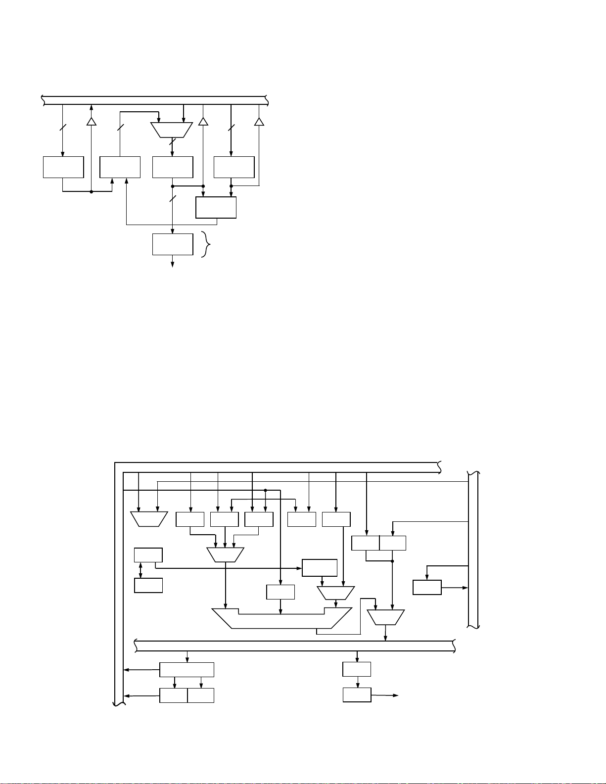
limitations and restrictions of the TMS320C50 can
present severe penalties in data addressing efficiency
for DSP algorithms and can result in data bottlenecks
and slower execution of DSP code.
The address generator can bit-reverse an address as it
is sent out to the address bus for zero-overhead bitreversing for the FFT. The I, M, and L registers can be
also used for general purpose data storage.
DATA MEMORY BUS
MUX
14
I
REGISTERS
4 X 14
14
BIT
REVERSE
ADDRESS
M
REGISTERS
4 X 14
ADD
DAG1 ONLY
14
L
REGISTERS
4 X 14
1414
MODULUS
LOGIC
Figure 3. Block Diagram of ADSP-2115 Data Address
Generators
ADSP-2115 Addressing
There are two independent address generators in the
ADSP-2115. One typically supplies addresses for program memory data fetches while the other handles data
memory, making efficient use of the modified Harvard
architecture. Each address generator has four I (index)
registers which store pointers (addresses), four M
(modify) registers for address modifiers, and four L
(length) registers storing buffer lengths for modulo addressing of circular buffers.
The address generators can also be used in conjunction
with the serial ports to provide an automatic data buffering function. As data words come in or go out the serial
port, data buffer addressing is automatically maintained
and an interrupt is generated when the buffer is full or
empty. This minimizes interrupt handling for serial port
data transfers.
ADSP-2115 Indirect Addressing
With indirect addressing, the address in an I register
drives either the data or program memory address bus.
While the memory is being accessed, the address is simultaneously updated with the contents of any of the
modify (M) registers, as shown in Figure 3. The specific
pairing of I and M registers is up to the programmer. For
example, I0 and M3 could be specified in the instruction
as in
AX0=DM(I0,M3); {load AX0 from Data Memory
and modify I0 by M3}
The ability to mix I registers and M registers is especially
useful for two-dimensional addressing or for supporting
pointer increment and decrement without constantly
reloading a new modify value. This instruction syntax
shows explicitly what registers are used to generate the
address and where the data is going; nothing has to be
inferred.
Loading the length of a circular buffer into the L register
activates the modulus logic, guaranteeing that the address is kept inside the buffer in a modulo fashion. This
DATA BUS (DATA)
MUX
ARP
ARB
CBER CBSR
MUX
DATA MEMORY
OVLY
CNF
ARCR
DATA BUS (ADDRESS)
NDXINDX
CBCR
ARAU(16)
AUXREGS
(8 X 16)
MUX
RRFR
BR
DP (9)
DMA (7)
MUX
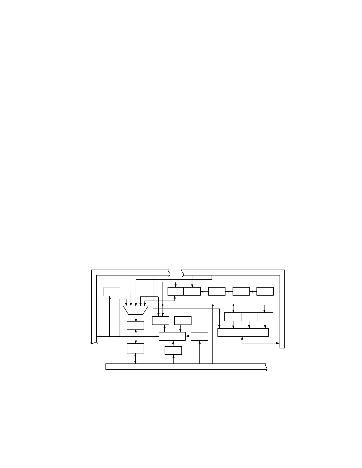
Figure 4. Block Diagram of TMS320C50 Address Generation Circuit
P
R
O
G
R
A
M
D
A
T
A
XF
B
U
S
–6–
Page 7

is maintained automatically by the address generator
hardware and does not have to be calculated explicitly
by the programmer. Circular buffers, such as for the delay lines of digital filters, are both transparent and require zero-overhead. Circular buffering is automatically
maintained regardless of the modify value used.
ADSP-2115 Direct Addressing
Due to the 24-bit width of the ADSP-2115 instruction, a
full 14-bit address can be specified within a (singleword) instruction for single-cycle access to any data.
Below is an example of an instruction using direct addressing to read from data memory.
MX0 = DM(some_label);
ADSP-2115 Circular Buffering
Circular buffering is supported in hardware by the address generators of the ADSP-2115. Each address generator can maintain four simultaneous circular buffers
for a total of eight. Circular buffers can be placed in either data or program memory. The length register (L
registers) is simply loaded with the length of the circular
buffer. The modulus logic detects when the pointer (updated index register value) has reached or exceeded the
end of the buffer boundary. Operation is supported for
going forwards or backwards through the buffer. The
step size can be of any value that is less than the
full buffer length. For applications such as interpolation
filters, where the step size is equal to the interpolation factor, zero-overhead circular buffer operation is
maintained.
TMS320C50 Addressing
The auxiliary register file of the TMS320C50 is used for
storage of addresses and a single modifier. Only one
address can be supplied at a time with the auxiliary register file so that two general purpose, indirect addressed
data fetches cannot be achieved in a single cycle.
TMS320C50 Indirect Addressing
The auxiliary register file is connected to an arithmetic
unit which will auto-index the contents of the auxiliary
register or modify a register by the contents of auxiliary
register number 0. The TMS320C50 has a single modify
register. This limits the addressing capabilities for indirect addressing. Limited support is provided for circular
modulo addressing; this diminishes the performance of
DSP algorithms using circular buffers. Automatic circular buffering is only supported for increment and decrement address modifications. Modify values greater than
1 will not work.
TMS320C50 Direct Addressing
The TMS320C50 can directly access data within a 128word block (compared to a 16K word block with the
ADSP-2115). A 9-bit data page register is used in conjunction with the direct address to access a larger data
space. To access data within a different block requires
software overhead to update the 9-bit data page register. The update of the page register poses the requirement on the programmer to detect when the page
boundary has been exceeded and when it is necessary
to update the page register.
TMS320C50 Circular Buffering
Two circular buffers can be maintained by hardware in
the address generation circuitry. A register (CBSR) is
used to hold the start address of the circular buffer and a
register (CBER) is used to hold the end address of the
circular buffer. Since the auxiliary registers are used for
pointers into the circular buffer, circular buffers in program memory (coefficients) are not possible. The circular buffer logic in the TMS320C50 checks only for a
pointer equal to the end address, it does not check for a
pointer that has skipped over the end address (i.e., using a step size greater than 1). For applications which
require a step size greater than 1, such as interpolation
filters, additional code (APL and OPL instructions) is
Table II. Summary of Data Addressing Capabilities
DSP Requirement ADSP-2115 TMS320C50
Single-Cycle Fetch of Two Operands from On-Chip ✓ No
Single-Cycle MAC Operations ✓✓*
Modify Two Addresses by Two Different Modify Values on Every Cycle ✓ No
Bit-Reverse Data Memory Addresses for FFT ✓✓
Automatic Pointer Wraparound for Circular Buffers ✓✓**
Automatic Circular Modulo Addressing ✓ No
*MAC, MACD, MADD and MADS instructions only.
**For step size of 1 only, and cannot be used for program memory.
–7–
Page 8

needed to monitor the value of the pointer. This requires
several cycles of overhead for each data word addressed. Also, the maximum circular buffer length supported by the TMS320C50 is 256, thus limiting the size of
digital filters that can be used.
TMS320C50 Addressing Instructions
The instruction mnemonics of the TMS320C50 involve
several addressing modes. Indirect and direct addressing is specified within arithmetic instructions and, depending upon the memory configuration, can impose
several overhead cycles (overhead can be as high as
eight cycles with external memory). Some general syntax examples are shown below.
The first example uses the contents of an auxiliary register as the address and the second uses the contents of
an auxiliary register as the address and adds the contents of auxiliary register 0 as a modifier. This instruction syntax can be hard to decipher because it does not
directly name which auxiliary register is being used.
That information is stored in the auxiliary register
pointer (ARP).
The address generator can bit-reverse an address as it is
sent out to the address bus for zero-overhead bit-reversing for the FFT. Auxiliary registers can also be used for
general purpose data storage and the auxiliary ALU can
be used for limited math.
ADD {*|*+|*-|*0+|*0-|*BRO+|*BRO-} [,<next ARP>]
MPY {*|*+|*-|*0+|*0-|*BRO+|*BRO-} [,<next ARP>]
Specific examples of these are shown below.
ADD *
MPY *0+
DMD BUS
ARITHMETIC
STATUS
IRQ0–3 4
STATUS LOGIC
STATUS STACK
MUX
STATUS
REGISTERS
4 (MASK)
INTERRUPT
CONTROLLER
4 X 16
16
COUNTER LOGIC
MUX
DOWN
COUNTER
CE OUT
16
COUNT STACK
4 X 14
ADDRESS GENERATION SUMMARY
Sustaining high rates of arithmetic operations demands
maximum performance from the data addressing part of
a processor’s architecture. Table II summarizes the differences between the two processors in terms of their
data addressing capabilities.
CONDITION CODE (4 BITS)
FROM INSTRUCTION REGISTER
4
14
CONDITION
LOGIC
ADDRESS OF JUMP (14 BITS)
FUNCTION FIELD
ADDRESS OF LAST
INSTRUCTION IN
LOOP (14 BITS)
AND
TERMINATION
CONDITION (4 BITS)
18
LOOP STACK
4 X 8
4
2
LOOP
COMPARATOR
14
14
PC STACK
16 X 14
NEXT ADDRESS MUX
PMA BUS
PROGRAM
COUNTER
INCREMENT
14
NEXT ADDRESS
SOURCE
SELECT
Figure 5. Block Diagram of the Program Sequencer of the ADSP-2115
–8–
MUX
Page 9
PROGRAM SEQUENCING CAPABILITIES
Efficient architectures for signal processing require fast
arithmetic capabilities and matching speed in data addressing and fetching capabilities. To fully deliver the
performance required for real-world signal processing,
a DSP machine must execute its program with little or
no overhead spent on maintaining the proper flow of
control.
Efficiency in program sequencing has many different
aspects; they cannot all be covered in this article. The
comparison focuses primarily on two features
• the execution of loops and
• how branching and branching on conditions are
handled.
Loops are fundamental to the way DSP algorithms are
expressed in their natural mathematical form. Operations such as sums-of-products are repetitive. If the program can be efficiently expressed in a looped form, then
coding is quite straight forward and changing the program (for example, to increase the number of taps in a
filter) requires very little work.
Branching is fundamental to program structure. Branching on conditions (and executing arithmetic on conditions) is a natural way to construct any program which
must respond to its environment.
Program Sequencer Architecture
Figure 5 shows the architecture of the program
sequencer of the ADSP-2115 and Figure 6 shows that
of the TMS320C50.
ADSP-2115 Program Sequencer
The program sequencer of the ADSP-2115 contains logic
that selects a program memory address source and
routes the address to the program memory address bus
(PMA). This address selection occurs automatically in
response to the current instruction. The address placed
on the address bus can come from
• the program counter (for sequential addressing),
• a 14-bit address in the instruction word itself, for direct jumps and subroutine calls,
• the PC stack, for returns from subroutines and interrupts, and
• the interrupt logic, to automatically vector to the
interrupt routine upon assertion of any external
interrupt.
All instructions execute in a single cycle; this applies
equally to jumps, calls and interrupts. No instruction
pipelining is required in the ADSP-2115 so that program
flow is simple to understand.
When an interrupt occurs, the complete status of the
processor (stack status, mode status, arithmetic status
and interrupt mask) is automatically pushed onto the
status stack as part of the interrupt vector process.
ADSP-2115 Looping Capabilities
The ADSP-2115 program sequencer supports zerooverhead “DO UNTIL” loops. Using the count stack,
loop stack and loop comparator, the processor can determine whether a loop should terminate and address
the next instruction (either the top of the loop or the instruction after the loop) with no overhead cycle.
PROGRAM BUS (ADDRESS)
BMAR
MUX
PC(16)
STACK
(8 X 16)
PASR
COMPARE
BRCR
INT#
IPTR
BRAF
PAER
DATA BUS (DATA)
PROGRAM BUS (DATA)
INTM
IMA IFR
MPMC
PROGRAM MEMORY
CNF RAM
Figure 6. Block Diagram of the TMS320C50 Program Sequencer Circuit
–9–
Page 10

A DO UNTIL loop may be as large as program memory
size permits, or as small as one instruction. A loop may
terminate when a 14-bit counter expires or when any
arithmetic condition occurs. The example below shows
a three instruction loop that is to be repeated 100 times.
CNTR = 100;
DO Label UNTIL CE;
First instruction of loop;
Second instruction of loop;
Label:
Last instruction of loop;
First instruction outside loop;
The first instruction loads the counter with 100. The DO
UNTIL instruction contains the address of the last instruction in the loop (in this case the address represented by the identifier,
termination condition (in this case the count expiring,
CE). The execution of the DO UNTIL instruction causes
the address of the first instruction of the loop to be
pushed on the PC stack and the address of the last instruction of the loop to be pushed on the loop stack.
(See Figure 5.)
As instruction addresses are output to the program
memory address bus and the instruction is fetched, the
loop comparator checks to see if the instruction is the
last instruction of the loop. If it is, the program sequencer checks the status and condition logic to see if
the termination condition is satisfied. The program sequencer then either takes the address from the PC stack
(to go back to the top of the loop) or simply increments
the PC (to go to the first instruction outside the loop).
The looping mechanism of the ADSP-2115 is automatic
and transparent to the user. As long as the DO UNTIL
instruction is specified, all stack and counter maintenance and program flow is handled by the sequencer
logic with no overhead. This means that in one cycle the
last instruction of the loop is being executed and in the
very next cycle, the first instruction of the loop is
executed or the first instruction outside the loop is
executed, depending upon whether the loop terminated
or not.
The ADSP-2115 can support four levels of nesting for
loops. DSP routines such as matrix operations and twodimensional processing, as well as more common algorithms such as the FFT, benefit from nested looping
capabilities.
ADSP-2115 Program Sequencer Instructions
There are many conditional instructions for the ADSP-
2115. Most arithmetic instructions as well as jumps, subroutine calls, returns from interrupts and returns from
subroutines may all be conditional. The program sequencer decides on the fly whether the condition is true
and what action to take, requiring zero overhead cycles.
Label
) and also contains the
The coding of conditional jumps, subroutine calls and
returns is straightforward. Some examples of the syntax
are shown below.
IF
condition
IF
condition
IF
condition
IF
condition
IF
condition
IF
condition
In the above examples, I4 references an address generator register for indirect branching.
any of a set of 16 arithmetic conditions in the processor
and
label
memory space.
TMS320C5x Program Sequencer
The program sequencer logic of the TMS320C5x controls instruction execution and consists of a program
counter, stack and related hardware. Figure 6 illustrates
the logic used for program sequencing.
Hardware looping on the C52 is supported by the RPT
(single instruction repeat) and the RPTB (multiple
instruction repeat) instructions, which can execute a
loop up to 65,536 times. These loops however are not interruptible. And though the RPT instruction can be nested
within an RPTB, to nest an RPTB instruction within an
RPBT instruction takes about 14 instructions of overhead
for saving and restoring control registers. Due to the limitations of instruction pipelining, the minimum size of a loop
used with a block repeat is three instructions. A two instruction zero-overhead loop is not possible.
A loop is maintained automatically but since there are
no local stacks or storage for loop count, top of loop address and bottom of loop address, there is no easy way
to have nested loops. Logic is also included to repeat a
single instruction as many as 256 times.
Instruction execution for the TMS320C50 utilizes a fourlevel pipeline consisting of a prefetch, decode, operand
fetch, and execution stage. The four level pipeline imposes certain restrictions and extra cycles of overhead
with operations such as loading data into registers,
looping, branching, and executing certain instructions
after other instructions. The ADSP-2115 has no such restrictions because it does not need the extra instruction
pipelining to achieve its fast speed.
Anytime the flow of the program deviates from sequential instruction fetches, the instruction pipeline must be
emptied and then refilled based on the destination address of the branch, call or interrupt vector. These types
of operations require at least three cycles to execute
when fetching the instruction from external memory or
from internal program ROM. This type of instruction
pipelining is not found in the ADSP-2115 (the fast instruction execution speed is achieved by other design
JUMP label;
JUMP I4;
CALL label;
CALL I4;
RTS;
RTI;
Condition
refers to any address or label in the program
refers to
–10–
Page 11

Table III. Summary of Program Sequencing Capabilities
DSP Requirement ADSP-2115 TMS320C50
PC Stack Depth 16 8
Nested Looping 4 Levels No
Conditional Arithmetic Instructions ✓ No
Zero-Overhead Branching ✓ No
Speed Achieved without Pipelining ✓ No, 4-Level Pipeline
Automatic Status Saving During Interrupt Vector ✓ No
techniques) and no extra overhead is encountered in the
ADSP-2115 for jumps, subroutines or interrupts regardless of whether they are conditional or not.
A prefetch counter (PFC) contains the address of the
next instruction to be prefetched. The prefetched instruction is loaded into the instruction register (IR), unless the instruction register still contains an instruction
currently executing. In this case, the prefetched instruction is temporarily stored in the queue instruction register (QIR). The instruction pipeline, in conjunction with
multi-cycle instruction execution, can make program
flow complex and difficult to understand. Calculating a
benchmark for a particular algorithm can also become
difficult for the same reason. The following code examples illustrate the counter-intuitive sequence of
events due to pipeline delays and the varying number of
execution cycles for different instructions.
The ADSP-2115 uses a single level of instruction pipeline where all instructions can execute in a single
cycle. Therefore, none of these problems exist with
the ADSP-2115.
The program counter of the TMS320C5x can supply an
address for sequential addressing. The single 8-deep PC
stack is used for storage of return addresses as well as
for providing the ability to push and pop data for the accumulator. An interrupt flag register (IFR) is used for
vectoring to an interrupt routine. Unlike the ADSP-2115,
status is not automatically saved on the TMS320C50
for interrupts so that the programmer must perform
any save and restore functions explicitly. Interrupt latency is 12 instruction cycles on the TM320C52 and 3
instruction cycles on the ADSP-2115. For interrupt
nesting to be used in the TMS320C52, an interrupt service routine has to reenable interrupts as one of the
initializing operations.
Branch instructions which contain a direct address require multiple program memory locations because both
the instruction bits and the address cannot fit in the 16bit instruction width. Delayed branches are required to
minimize the overhead introduced by the instruction
pipelining. Even with the use of delayed branches, as
many as two cycles of overhead are required with the
TMS320C50, where no overhead cycles are required
with the ADSP-2115. Also, with the TMS320C50, the
number of overhead cycles for a conditional branch will
vary depending upon whether the condition is met or
not.
PROB1 LAR AR2,#067h ;AR2 = 0x67.
LACC #064h ;ACC = 0x64.
SAMM AR2 ;This update is overridden by *- updates
;on the next two instructions
LACC *- ;AR2 = 0x66.
ADD *- ;AR2 = 0x65.
PROB2 LAR AR2,#067h ;AR2 = 0x67.
LACC #064h ;ACC = 0x64.
SAMM AR2 ;LACC *- update happens before SAMM write
LACC *- ;AR2 = 0x66.
NOP ;AR2 = 0x64 SAMM write to AR2 happens
;between instructions.
ADD *- ;AR2 = 0x63.
–11–
Page 12

TMS320C5x Program Sequencer Instructions
Arithmetic instructions cannot be conditional. Only
branch instructions are conditional. Branch instructions
with direct addresses require two program memory
words due to the 16-bit instruction word.
BACC
BANZ <address>
There are many multiword instructions for the
TMS320C50 because of the 16-bit size of the instruction word. This means that two or more fetches are
required, which takes extra time. The ADSP-2115 has
a 24-bit wide instruction and no multiword instructions are n ecessary.
PROGRAM SEQUENCER SUMMARY
Efficient looping capabilities are very important for DSP
algorithms due to their repetitive nature. Also, zerooverhead jump and conditional branching is important
where many decisions have to be made such as in
speech processing. Table III summarizes the program sequencer capabilities of the ADSP-2115 and
TMS320C50.
I/O HANDLING CAPABILITIES
A final area of efficiency is that of I/O handling. Memories, A/D and D/A converters, as well as EPROM for program booting will need to efficiently interface to the DSP
processor to minimize extra logic and software overhead to drive external peripherals. The ADSP-2115 has
several features relating to I/O handling which simplify
DSP system design and which are not found on the
TMS320C50.
Automatic Boot Loading From External Byte-Wide
Memory
The ADSP-2115 directly interfaces to a single byte-wide
EPROM for efficient program boot loading. No extra
components are needed since the EPROM can directly
connect to the address and data lines of the ADSP-2115 .
A boot memory select pin (BMS) on the ADSP-2115 is
tied directly to the chip select pin of the EPROM and the
read line (RD) is directly connected to the output enable
pin of the EPROM. The boot memory space consists of
an external 64K x 8 space divided into eight separate 8K
x 8 pages. At reset, boot page 0 is automatically transferred in to the internal RAM of the ADSP-2115. Under
program control, any of the eight pages can be boot
loaded into the internal RAM of the ADSP-2115 with access time being programmable.
Flexible Serial Ports
Both devices have two serial ports. The serial ports of
the ADSP-2115 have some additional features which
makes their operation more flexible. The word width of
the data to be transmitted and received is programmable and can be set for any size from 3 bits to 16 bits.
On the TMS320C50, the word width is limited to 8 or 16
bits.
The address generators of the ADSP-2115 can be used in
conjunction with the serial ports to provide an automatic
data buffering capability. Normally, an interrupt is generated after each word is transferred through the serial
port. If many words are to be transferred (i.e., data buffers filled for a speech application), there can be an excess of interrupt overhead associated with the serial
ports. The ADSP-2115 allows autobuffering where a
length is specified along with a buffer start address and
a modify value (any integer value which is used to update the address). As each word is transferred through
the serial port, the data is automatically read from or
written to data memory, transparent to the user, with no
interrupt being generated. An interrupt is generated
only when the buffer is full or empty. One of the serial
ports of the ADSP-2115 also supports a multichannel
word stream for easy interface to a T1 or CEPT data
stream. The TM320C52 does not support a TDM (multichannel) mode of operation. The other members of the
family support only 8 channels. One ADSP-2115 serial
port supports multichannel transfers of either 24 or 32
channels. Serial ports on the ADSP-2115 support the
G.711 recommendation for µ-law and A-law companding in hardware of data for interface to voice band
codecs. Companding is an operation that is used to
logarithmically compress data from 16 bits to 8 bits or
expand 8-bit wide compressed data to 16 bits. Zero
overhead companding of data is supported during
transmit and receive. Internal companding is also supported for local compression and expansion purposes.
SUMMARY
The DSP processors available on the market today vary
drastically in their ability to meet the five key requirements of DSP processing. In fact, some DSP-oriented
processors, like the TMS320C50, are better high-speed
microcontrollers than they are DSP processors. Analyzing the requirements of your DSP system and matching
them to the capabilities of a DSP architecture will assure
efficient operation. Overall the straightforward architecture and the algebraic syntax of the instruction set for
the ADSP-2115 processor allows the programmer to
spend more time concentrating on a complex DSP algorithm instead of spending time optimizing code for an
unnecessarily complex architecture.
Due to space limits, this article does not cover many
topics in detail. Consult the
Manual
Manual
processor.
APPENDIX: PROGRAM EXAMPLE
To illustrate some of the issues discussed above, a code
example is shown below for the ADSP-2115 and the
TMS320C50. To avoid long listings and confusion, a
short program which performs the LMS adaption of FIR
filter coefficients is shown. Both processors perform
and the
for a greater depth of information on this
ADSP-2100 Family Assembler Tools
ADSP-2100 Family User’s
–12–
Page 13

AR=DM(Error); {Get Err Value From Mem }
MY1=Beta; {Load Beta Value }
MF=AR*MY1(RND), AY0=PM(I4,M4), MX0=DM(I0,M0); {MF=Beta*Err, Get Ck, A }
MR=MX0*MF(RND); {MR=Beta*Error*A(n) }
CNTR=A; {Set Loop Counter }
DO uloop UNTIL CE; {Tap Update Loop }
AR=MR1+AY0, AY0=PM(I4,M6), MX0=DM(I0,M1); {AR=Ck+Beta*Error*A(n) }
uloop: PM(I4,M7)=AR, MR=MX0*MF(RND); {Store CK+1, Do Next }
RTS; {Return}
identical tasks so that no interpretation of the type of algorithm is required. Both code examples do not show
any initialization of pointers or the set up of any modes.
For simplicity, the examples only focus on the core
operation.
Because these examples are short, the performance advantages of the ADSP-2115 is not as apparent as in a
more sophisticated example. Nevertheless, the ease of
coding and the benefits of the instruction syntax and the
architecture can be seen.
ADSP-2115 Code Example Description
The example shown implements an adaptive update of
FIR filter coefficients. The formula used is expressed as
Ck+1=Ck+Beta*Error*A(n).
The program segment shown was taken from the book
Digital Signal Processing Applications Using The ADSP2100 Family
The code shown uses the looping capabilities of the
ADSP-2115 and can be easily expanded for a larger
number of coefficients by simply changing the number
of loops (the value loaded into the counter). Indirect addressing is used to address the coefficient buffer Ck and
the input data buffer A(n). The address registers I0 and
I4 are used for addressing of these two buffers.
The first advantage of the ADSP-2115 is its algebraic
syntax for assembly language code. The routine starts
with a fetch of the error term from data memory. This
value is loaded into the register AR. AR is the ALU result
register, but it is used as a general purpose data register
in this example. The next line of code loads an immediate value, the beta value, into register MY1. MY1 is one
of the input registers of the multiplier for the Y operand.
With the error value in register AR and the beta value in
register MY1, a multiplication of these two values is
specified. The multiplication is performed with the result rounded to the most significant 16-bits with an unbiased rounding scheme. This multifunction instruction
also specifies the fetch of the coefficient , Ck, from program memory and the data value A(n) from data
memory. Note that the I register specifies which address
register is used as a pointer and the M register specifies
how the address is modified. This ADSP-2115 addressing capability is a key advantage to that of the
TMS320C50. The multiplication, the program memory
,
Volume I
, published by Prentice Hall.
fetch and the data memory fetch all occur in a single
cycle. The result of the multiplication is loaded into MF,
the multiplier feedback register. This value is used immediately in the next cycle where a multiplication is performed using the MX0 register (holding the A(n) term)
and the MF register (holding the product beta*error).
Rounding is again specified.
The counter is next loaded with the number of coefficients to be updated and a DO UNTIL instruction is
specified to set up the loop logic of the ADSP-2115. The
core instructions of the loop calculate the result Ck+1
and also set up the calculations for the next update. Results are written into program memory in the last instruction of the loop.
Finally, a return from subroutine instruction is specified
to return control back to the calling program.
ADSP-2115 Performance Benchmark
The code section shown uses the looping capabilities of
the ADSP-2115 and can be easily modified for any number of coefficients by simply changing the counter value.
A total of nine instructions are used in the LMS adaption
of FIR filter coefficients where each instruction executes
in a single processor cycle. The two instructions in the
core of the loop are repeated for each coefficient update.
Therefore, the benchmark for the number of cycles
required for this routine can be generally expressed as
7+n*2
, where n is the number of coefficients to be
updated.
For a 127 TAP filter (which requires 127 coefficients), an
update can be performed in 7+127*2 = 261 cycles.
TMS320C50 Code Example Description
The example shown implements an adaptive update of
FIR filter coefficients. The formula used is expressed as
a0(i+1)=a0(i)+Beta*err*X(i).
This is the same LMS adaptive update as shown for the
ADSP-2101, the equation has just been stated with different terms. The program segment shown is described
in the book
Texas Instruments.
This is an example of looped code based on the RTPB
(repeat block) instruction. Indirect addressing is used to
address the coefficient buffer a(i) and the input data
buffer x(i). The auxiliary registers AR2 and AR3 are used
to address these two buffers.
TMS320C5x User’s Guide
published by
–13–
Page 14

LT ERR ; T=Err
MPY BETA ; P=Beta*Err(i)
PAC ; errf(i)=Beta*Err(i)
ADD ONE, 14 ; Round The Results
SACH ERRF,1 ; Save errf(i)
LACC #126
SAMM BRCR ; 127 Coeffs To Update In The Loop
LAR AR2, #COEFFD ; Point To The Coefficients
LAR AR3, #LASTAP ; Point To The Data Samples
LT ERRF
MPY *-,AR2 ; P=Beta*Err(i)*x(i-255)
RPTB LOOP-1 ; For I=0, I<=126, I++
ADAPT ZALR *,AR3 ; Load ACCH With Ak(i)
MPYA *-,AR2 ; P=Beta*Err(i)*X(i-k-1),
ACC=ak(i)+Beta*err(i)*x(i-k)
SACH *+ ; Store ak(i+1)
LOOP ZALR *,AR3 ; Final Update Last Coefficient a0(i)
RETD ; Delayed Return
APAC ; ACC=a0(i)+Beta*Err(i)*x(i)
SACH *+ ; Save a0(i+1)
The LMS adaption routine starts by loading the error
stored in the memory location “ERR” into the TREG0
register for multiplication. The LT instruction is used to
load the T register. Once the error is loaded, then the
error is multiplied by the Beta value stored in the
memory location “BETA”. The results (error*beta) resides in the P register of the multiplier. Because of the
inflexibility of the TMS320C50 architecture, the multiplier result must be moved explicitly into the accumulator. PAC is used to place the product into the
accumulator for further computation. The error*beta
term can then be rounded to 16-bit precision with the
instruction “ADD ONE,14” and stored into a memory location with the SACH instruction. The rounding takes an
extra instruction. On the ADSP-2115, this function can
be performed as part of the multiply.
At this point in the program, the loop to calculate all of
the new coefficients can be set up. There are 127 coefficients in this example, so the loop counter BRCR can be
initialized with the constant 126. On the ADSP-2115, the
programmer loads the loop counter directly with the
number of loop iterations. Two instructions are required
to load the loop counter, LACC and SAMM.
Indirect accesses using the auxiliary registers AR2 and
AR3 are used within the loop. These registers can be initialized with the LAR instruction prior to entering the
loop.
The error*beta term can then be reloaded back into the
T register for multiplication with the tapped delay line
values. The “LT ERRF” instruction loads this value and
the “MPY *-,AR2” performs the first multiply outside of
the loop. This reloading of partial results is required because of the inflexibility of the TMS320C50 architecture.
The algorithm needs to be rearranged due to limitations
of the hardware. The ADSP-2115 makes use of a more
flexible bus structure where data can be fed back immediately without the need for temporary storage of intermediate results in memory.
The RTPB instruction performs the block repeat. As an
argument, this instruction needs the end of loop address
minus one. The three instructions ZALR, MPYA and
SACH are executed in the loop 127 times. Notice that the
programmer must label the instruction after the last instruction in the loop. The ADSP-2115 uses a much more
understandable looping format where the last instruction in the loop is labeled. Any size loop is possible on
the ADSP-2115 . The TMS320C50 block repeat is useful
only for loops of three instructions or larger.
After completion of the loop, the last tap is updated and
a delayed return is executed. A delayed return is necessary because of the instruction pipelining found in the
TMS320C50. This type of instruction pipelining is not
found in the ADSP-2115 and delayed instructions are,
therefore, not necessary.
TMS320C50 Performance Benchmark
A total of 19 instructions are used in the LMS adaption of
FIR filter coefficients. All instructions, however, will not
execute in a single processor cycle. The three instructions in the core of the loop are repeated for each coefficient update. Therefore, the benchmark for the number
of cycles required for this routine can be generally expressed as
17+n*3
dated.
, where n is the number of coefficients to be up-
–14–
Page 15

For a 127 TAP filter (which requires 127 coefficients), an
update can be performed in 17+127*3 = 398 cycles.
Table IV. ADSP-2115 vs. TMS320C50
Function 2115KP-80 C52-57
Cycle Time 50 ns 35 ns
MIPS 20 28.57
Biquad IIR Filter 350 ns 350 ns
LMS Adaptive Filter
Tap Update 100 ns 140 ns
1024-Point
Complex FFT 1.86 ms 2.45 ms
256-Point FFT 685 µs 731 µs
Don't be fooled—you can't judge a DSP by cycle or MIPS
alone! Even though the TMS320C52 has higher MIPS
than the ADSP-2115, the ADSP-2115 does much better in
benchmarks. Look closely at the biquad IIR filter benchmark—it takes the TMS320C52 over 28 MIPS to do what
the ADSP-2115 can do with less MIPS! The ADSP-2115
executes faster because it's architecture is optimized for
signal processing.
–15–
Page 16

E1985–5–12/94
–16–
PRINTED IN U.S.A.
 Loading...