


12-Bit, Integrated, Multiformat SDTV/HDTV
www.BDTIC.com/ADI
Video Decoder and RGB Graphics Digitizer
FEATURES
Four Noise Shaped Video® 12-bit ADCs sampling up to
140 MHz (140 MHz speed grade only)
12 analog input channel mux
SCART fast blank support
Internal antialias filters
NTSC/PAL/SECAM color standards support
525p-/625p-component progressive scan
720p-/1080i-component HDTV support
Digitizes RGB graphics up to 1280 × 1024 @ 75 Hz (SXGA)
(140 MHz speed grade only)
24-bit digital input port supports data from DVI/HDMI Rx IC
Any-to-any, 3 × 3 color-space conversion matrix
Industrial temperature range (−40°C to +85°C)
12-bit 4:4:4/10-/8-bit 4:2:2 DDR pixel output interface
Programmable interrupt request output pin
VBI data slicer (including teletext)
APPLICATIONS
LCD/DLP™ rear projection HDTVs
PDP HDTVs
CRT HDTVs
LCD/DLP front projectors
LCD TV (HDTV ready)
HDTV STBs with PVR
Hard-disk-based video recorders
Multiformat scan converters
DVD recorders with progressive scan input support
AVR receiver
support
ADV7403
GENERAL DESCRIPTION
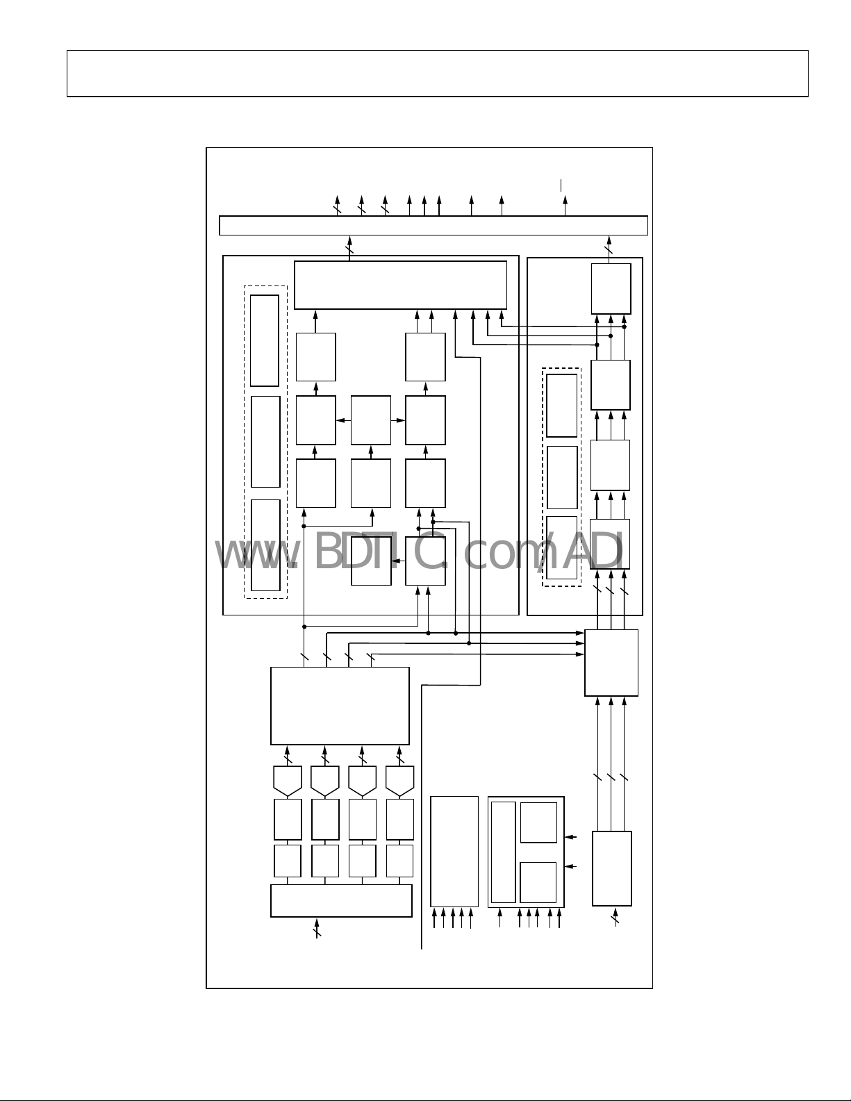
The ADV7403 is a high quality, single chip, multiformat video
decoder and graphics digitizer. This multiformat decoder
supports the conversion of PAL, NTSC, and SECAM standards
in the form of composite or S-video into a digital ITU-R BT.656
format. The ADV7403 also supports the decoding of a
component RGB/YPrPb video signal into a digital YCrCb or
RGB pixel output stream. The support for component video
includes standards such as 525i, 625i, 525p, 625p, 720p, 1080i,
1250i, and many other HD and SMPTE standards. Graphic
digitization is also supported by the ADV7403; it is capable of
digitizing RGB graphics signals from VGA to SXGA rates and
converting them into a digital RGB or YCrCb pixel output
stream. SCART and overlay functionality are enabled by the
ADV7403’s ability to simultaneously process CVBS and
standard definition RGB signals. The mixing of these signals is
controlled by the fast blank pin.
The ADV7403 contains two main processing sections. The first
he standard definition processor (SDP), which processes all
is t
PAL, NTSC, and SECAM signal types. The second is the
component processor (CP), which processes YPrPb and RGB
component formats, including RGB graphics. For more specific
descriptions of the ADV7403 features, see the
nctionality and Detailed Description sections.
Fu
Detailed
Rev. SpA
Information furnished by Analog Devices is believed to be accurate and reliable.
However, no responsibility is assumed by Analog Devices for its use, nor for any
infringements of patents or other rights of third parties that may result from its use.
Specifications subject to change without notice. No license is granted by implication
or otherwise under any patent or patent rights of Analog Devices. Trademarks and
registered trademarks are the property of their respective owners.
One Technology Way, P.O. Box 9106, Norwood, MA 02062-9106, U.S.A.
Tel: 781.329.4700 www.analog.com
Fax: 781.461.3113 © 2005 Analog Devices, Inc. All rights reserved.
ADV7403
www.BDTIC.com/ADI
TABLE OF CONTENTS
Functional Block Diagram .............................................................. 3
CP Pixel Data Output Modes ................................................... 13
Electrical Characteristics ................................................................. 4
Video Specifications......................................................................... 6
Timing Characteristics..................................................................... 7
Analog Specifications....................................................................... 8
Absolute Maximum Ratings............................................................ 9
Stress Ratings ................................................................................ 9
Package Thermal Performance................................................... 9
Thermal Specifications ................................................................ 9
ESD Caution.................................................................................. 9
Pin Configuration and Function Descriptions........................... 10
Timing Diagrams............................................................................ 12
Detailed Functionality ................................................................... 13
Analog Front End....................................................................... 13
SDP Pixel Data Output Modes ................................................. 13
Composite and S-Video Processing......................................... 13
Component Video Processing.................................................. 14
RGB Graphics Processing ......................................................... 14
Digital Video Input Port............................................................ 14
General Features......................................................................... 14
Detailed Description...................................................................... 15
Analog Front End....................................................................... 15
Standard Definition Processor ................................................. 15
Component Processor ............................................................... 15
Pixel Input/Output Formatting .................................................... 17
Recommended External Loop Filter Components.................... 19
Typical C o n necti on D i a g ram ....................................................... 20
Outline Dimensions ....................................................................... 21
Ordering Guide .......................................................................... 21
REVISION HISTORY
9/05—Rev. Sp0 to Rev. SpA
Deleted EDTV.....................................................................Universal
Added AVR Receiver to Applications Section .............................. 1
Change to Crystal Normal Frequency Typ Value in Table 3 ...... 7
Changes to Figure 2 ....................................................................... 10
Changes to Function Descriptions of Pin 37 and Pin 38 .......... 11
Change Pin 70 Type........................................................................ 11
Change to Crystal MHz Unit Value............................................. 13
Added Pixel Input Information to Table 9 and Table 10........... 17
Changes to Figure 9........................................................................ 20
4/05—Revision Sp0: Initial Version
Rev. SpA | Page 2 of 24
ADV7403
www.BDTIC.com/ADI
FUNCTIONAL BLOCK DIAGRAM
P29–P20
P19–P10
P9–P0
PIXEL
DATA
HS
VS
FIELD/DE
LLC1
SFL/
8
8
OUTPUT FIFO AND FORMATTER
8
SYNCOUT
INT
VBI DATA RECOVERY
STANDARD
AUTODETECTION
STANDARD DEFINITION PROCESSOR
DETECTION
MACROVISION
CVBS/Y
Y
LUMA
(5H MAX)
2D COMB
LUMA
RESAMPLE
LUMA
FILTER
20
AND
FAST
BLANK
AV CODE
OVERLAY
CONTROL
INSERTION
Cb
(4H MAX)
2D COMB
RESAMPLE
FILTER
DEMOD
Cr
Y
Cr
Cb
CGMS DATA
COMPONENT PROCESSOR
MACROVISION
ACTIVE PEAK
Cb
CONTROL
RESAMPLE
SYNC
EXTRACT
SC
F
RECOVERY
Cr
CHROMA
CHROMA
CHROMA
CHROMA
C
CVBS
EXTRACTION
DETECTION
AND
AGC
30
12
AV CODE
INSERTION
OFFSET
CONTROL
GAIN
CONTROL
FINE
CLAMP
DIGITAL
12
12
12
ADV7403
ANTI-
DATA
PREPROCESSOR
A/DCLAMP
ALIAS
121212
FILTER
12
AIN1
12
COLORSPACE
CONVERSION
AND
FILTERS
DECIMATION
DOWNSAMPLING
12
12
12
SOY
888
XTAL1
XTAL
DIGITAL INPUT
P40–P31
PORT
DVI or HDMI
24
P1–P0
P11–P10
P29–P20
05431-001
A/DCLAMP
A/DCLAMP
A/DCLAMP
ANTI-
ANTI-
ANTI-
ALIAS
FILTER
MUX
INPUT
CVBS
AIN12
S-VIDEO
YPrPb
TO
ALIAS
SCART–
FILTER
(RGB + CVBS)
GRAPHICS RGB
ALIAS
FILTER
FB
SCLK
SERIAL INTERFACE
SDA
SCLK2
CONTROL AND VBI DATA
SDA2
STDI
SSPD
CLOCK GENERATION
SYNC PROCESSING AND
ALSB
DCLK_IN
SOG
VS_IN
DE_IN
HS_IN
Figure 1.
Rev. SpA | Page 3 of 24
ADV7403
www.BDTIC.com/ADI
ELECTRICAL CHARACTERISTICS
@ AVDD = 3.15 V to 3.45 V, DVDD = 1.65 V to 2.0 V, DVDDIO = 3.0 V to 3.6 V, PVDD = 1.71 V to 1.89 V, nominal input range 1.6 V.
Operating temperature range, a otherwise noted.
Table 1.
Parameter
STATIC PERFORMANCE
Resolution (each ADC) N 12 Bits
Integral Nonlinearity INL BSL at 27 MHz (at a 12-bit level) ±2.0 ±8.0 LSB
Integral Nonlinearity INL BSL at 54 MHz (at a 12-bit level) −2.0/+2.5 LSB
Integral Nonlinearity INL BSL at 74 MHz (at a 10-bit level) ±1.0 LSB
Integral Nonlinearity INL BSL at 110 MHz (at a 10-bit level) −3.0/+3.0 LSB
Integral Nonlinearity INL BSL at 135 MHz (at an 8-bit level)
Differential Nonlinearity DNL At 27 MHz (at a 12-bit level) −0.7/+0.85 −0.99/+2.5 LSB
Differential Nonlinearity DNL At 54 MHz (at a 12-bit level) −0.75/+0.9 LSB
Differential Nonlinearity DNL At 74 MHz (at a 10-bit level) ±0.75 LSB
Differential Nonlinearity DNL At 110 MHz (at a 10-bit level) −0.7/+5.0 LSB
Differential Nonlinearity DNL At 135 MHz (at an 8-bit level)6
DIGITAL INPUTS
Input High Voltage
Input Low Voltage
Input High Voltage V
Input Low Voltage V
Input Current I
All other input pins −10 +10 μA
Input Capacitance
DIGITAL OUTPUTS
Output High Voltage
Output Low Voltage
High Impedance Leakage Current I
All other output pins 10 μA
Output Capacitance
POWER REQUIREMENTS
Digital Core Power Supply DVDD 1.65 1.8 2 V
Digital I/O Power Supply DVDDIO 3.0 3.3 3.6 V
PLL Power Supply PVDD 1.71 1.8 1.89 V
Analog Power Supply AVDD 3.15 3.3 3.45 V
Digital Core Supply Current IDVDD CVBS input sampling at 54 MHz 105 mA
Graphics RGB sampling at 135 MHz 137 mA
SCART RGB FB sampling at 54 MHz 106 mA
Digital I/O Supply Current IDVDDIO CVBS input sampling at 54 MHz 4 mA
Graphics RGB sampling at 135 MHz 19 mA
PLL Supply Current IPVDD CVBS input sampling at 54 MHz 11 mA
Graphics RGB sampling at135 MHz 12 mA
Analog Supply Current
Graphics RGB sampling at 135 MHz 242 mA
SCART RGB FB sampling at 54 MHz 269 mA
Power-Down Current IPWRDN 2.25 mA
Green Mode Power-Down IPWRDNG Sync bypass function 16 mA
Power-Up Time TPWRUP 20 ms
1
The min/max specifications are guaranteed over this range.
2
Temperature range T
3
All specifications obtained using programming scripts with the following sequence included: Addr 0x0E - data 0x80, Addr 0x54 - data 0x00, Addr 0x0E - data 0x00.
1, , 2 3
4, 5
7
8
10
11
11
10
10
13
to T
MIN
: −40°C to +85°C (0°C to 70°C temperature range for ADV7403KSTZ-140).
MAX
Symbol Test Conditions Min Typ Max Unit
6
±1.3 LSB
LSB
V
V
C
V
V
C
IH
IL
IH
IL
IN
IN
OH
OL
LEAK
OUT
−0.8/+2.5
2 V
0.8 V
HS_IN, VS_IN low trigger mode 0.7 V
HS_IN, VS_IN low trigger mode 0.3 V
Pins listed in Note 9 −60 +60 μA
10 pF
ISOURCE = 0.4 mA 2.4 V
ISINK = 3.2 mA 0.4 V
Pins listed in Note 12 60 μA
20 pF
IAVDD CVBS input sampling at 54 MHz 99 mA
Rev. SpA | Page 4 of 24
ADV7403
www.BDTIC.com/ADI
4
All ADC linearity tests performed at input range of full scale − 12.5%, and at zero scale + 12.5%.
5
Max INL and DNL specifications obtained with part configured for component video input.
6
Specification for ADV7403KSTZ-140 only.
7
To obtain specified VIH level on Pin 38, Register 0x13 (wo) must be programmed with value 0x04. If Register 0x13 is programmed with value 0x00,
then V
on Pin 38 = 1.2 V.
IH
8
To obtain specified VIL level on Pin 38, Register 0x13 (wo) must be programmed with value 0x04. If Register 0x13 is programmed with value 0x00,
then V
on Pin 38 = 0.4 V.
IL
9
Pins 1, 2, 13, 14, 16, 19, 24, 29, 30, 31, 32, 33, 34, 35, 45, 78, 79, 83, 84, 87, 88, 95, 96, 97, 100.
10
Guaranteed by characterization.
11
VOH and VOL levels obtained using default drive strength value (0xD5) in Register Subaddress 0xF4.
12
Pins 3, 13, 14, 19, 24, 29, 30, 31, 32, 33, 34, 45.
13
Analog current measurements for CVBS made with ADC0 powered up only, For RGB, ADC0, ADC1, and ADC2 powered up only, for SCART FB, all ADCs powered up.
Rev. SpA | Page 5 of 24
ADV7403
www.BDTIC.com/ADI
VIDEO SPECIFICATIONS
@ AVDD= 3.15 V to 3.45 V, DVDD = 1.65 V to 2.0 V, DVDDIO = 3.0 V to 3.6 V, PVDD = 1.71 V to 1.89 V. Operating temperature range,
unless otherwise noted.
Table 2.
Parameter
NONLINEAR SPECIFICATIONS
Differential Phase DP CVBS input, modulated 5 step 0.4 degree
Differential Gain DG CVBS input, modulated 5 step 0.4 %
Luma Nonlinearity LNL CVBS input, 5 step 0.4 %
NOISE SPECIFICATIONS
SNR Unweighted Luma ramp 61 64 dB
SNR Unweighted Luma flat field 64 65 dB
Analog Front End Crosstalk 60 dB
LOCK TIME SPECIFICATIONS
Horizontal Lock Range −5 +5 %
Vertical Lock Range 40 70 Hz
FSC Subcarrier Lock Range ±1.3 kHz
Color Lock in Time 60 line
Sync Depth Range
Color Burst Range 5 200 %
Vertical Lock Time 2 field
Horizontal Lock Time 100 line
CHROMA SPECIFICATIONS
Hue Accuracy HUE 1 degree
Color Saturation Accuracy CL_AC 1 %
Color AGC Range 5 400 %
Chroma Amplitude Error 0.4 %
Chroma Phase Error 0.3 degree
Chroma Luma Intermodulation 0.1 %
LUMA SPECIFICATIONS
Luma Brightness Accuracy CVBS, 1 V input 1 %
Luma Contrast Accuracy CVBS, 1 V input 1 %
1
The min/max specifications are guaranteed over this range.
2
Temperature range T
3
Guaranteed by characterization.
4
Nominal sync depth is 300 mV at 100% sync depth range.
1, , 2 3
4
to T
MIN
: −40°C to +85°C (0°C to 70°C temperature range for ADV7403KSTZ-140).
MAX
Symbol Test Conditions Min Typ Max Unit
20 200 %
Rev. SpA | Page 6 of 24
ADV7403
www.BDTIC.com/ADI
TIMING CHARACTERISTICS
@ AVDD = 3.15 V to 3.45 V, DVDD = 1.65 V to 2.0 V, DVDDIO = 3.0 V to 3.6 V, PVDD = 1.71 V to 1.89 V. Operating temperature range,
unless otherwise noted.
Table 3.
Parameter
SYSTEM CLOCK AND CRYSTAL
Crystal Nominal Frequency 28.63636 MHz
Crystal Frequency Stability ±50 ppm
Horizontal Sync Input Frequency 14.8 110 kHz
LLC1 Frequency Range
I2C PORT
SCLK Frequency 400 kHz
SCLK Min Pulse Width High t
SCLK Min Pulse Width Low t
Hold Time (Start Condition) t
Setup Time (Start Condition) t
SDA Setup Time t
SCLK and SDA Rise Time t
SCLK and SDA Fall Time t
Setup Time for Stop Condition t
RESET FEATURE
Reset Pulse Width 5 ms
CLOCK OUTPUTS
LLC1 Mark Space Ratio t9:t
DATA and CONTROL OUTPUTS
Data Output Transition Time SDR (SDP)
Data Output Transition Time SDR (SDP)
Data Output Transition Time SDR (CP)
Data Output Transition Time SDR (CP)
Data Output Transition Time DDR (CP)
Data Output Transition Time DDR (CP)
Data Output Transition Time DDR (CP)
Data Output Transition Time DDR (CP)
DATA and CONTROL INPUTS
Input Setup Time (Digital Input Port) t
DE_IN, data inputs 2.2 ns
Input Hold Time (Digital Input Port) t
DE_IN, data inputs 2 ns
1
The min/max specifications are guaranteed over this range.
2
Temperature range T
3
Guaranteed by characterization.
4
Maximum LLC1 frequency is 110 MHz for ADV7403BSTZ-110.
5
TTL input values are 0 V to 3 V, with rise/fall times ≥3 ns, measured between the 10% and 90% points.
6
SDP timing figures obtained using default drive strength value (0xD5) in register subaddress 0xF4.
7
CP timing figures obtained using max drive strength value (0xFF) in Register Subaddress 0xF4.
8
DDR timing specifications dependent on LLC1 output pixel clock; TLCC1/4 = 9.25 ns at LLC1 = 27 MHz.
1, , 2 3
4
5
5
to T
MIN
: −40°C to +85°C (0°C to 70°C temperature range for ADV7403KSTZ-140).
MAX
Symbol Test Conditions Min Typ Max Unit
12.825 140 MHz
1
2
3
4
5
6
7
8
10
6
t
11
6
t
12
7
t
13
7
t
14
7, 8
t
15
7, 8
t
16
7, 8
t
17
7, 8
t
18
19
20
0.6 μs
1.3 μs
0.6 μs
0.6 μs
100 ns
300 ns
300 ns
0.6 μs
45:55 55:45
Negative clock edge to start of
3.6 ns
valid data
End of valid data to negative
2.4 ns
clock edge
End of valid data to negative
2.8 ns
clock edge
Negative clock edge to start of
0.1 ns
valid data
Positive clock edge to end of
−4 + TLLC1/4 ns
valid data
Positive clock edge to start of
0.25 + TLLC1/4 ns
valid data
Negative clock edge to end of
−2.95 + TLLC1/4 ns
valid data
Negative clock edge to start of
−0.5 + TLLC1/4 ns
valid data
HS_IN, VS_IN 9 ns
HS_IN, VS_IN 7 ns
% duty
cycle
Rev. SpA | Page 7 of 24
ADV7403
www.BDTIC.com/ADI
ANALOG SPECIFICATIONS
@ AVDD = 3.1.5 V to 3.45 V, DVDD = 1.65 V to 2.0 V, DVDDIO = 3.0 V to 3.6 V, PVDD = 1.71 V to 1.89 V. Operating temperature
range, unless otherwise noted. Recommended analog input video signal range: 0.5 V to 1.6V , typically 1 V p-p.
Table 4.
Parameter
CLAMP CIRCUITRY
External Clamp Capacitor 0.1 μF
Input Impedance
Input Impedance of Pin 51 (FB) 20 kΩ
CML 1.86 V
ADC Full-Scale Level CML + 0.8 V V
ADC Zero-Scale Level CML − 0.8 V V
ADC Dynamic Range 1.6 V
Clamp Level (When Locked) CVBS input CML − 0.292 V V
SCART RGB input (R, G, B signals) CML − 0.4 V V
S-Video input (Y signal) CML − 0.292 V V
S-Video input (C signal) CML – 0 V V
Component input (Y, Pr, Pb signals) CML – 0.3 V V
PC RGB input (R, G, B signals) CML − 0.3 V V
Large Clamp Source Current SDP only 0.75 mA
Large Clamp Sink Current SDP only 0.9 mA
Fine Clamp Source Current SDP only 17 μA
Fine Clamp Sink Current SDP only 17 μA
1
The min/max specifications are guaranteed over this range.
2
Temperature range T
3
Guaranteed by characterization.
4
Except Pin 51 (FB).
1, , 2 3
4
to T
MIN
:−40°C to +85°C (0°C to 70°C temperature range for ADV7403KSTZ-140).
MAX
Test Conditions Min Typ Max Unit
Clamps switched off 10 MΩ
Rev. SpA | Page 8 of 24

ADV7403
www.BDTIC.com/ADI
ABSOLUTE MAXIMUM RATINGS
Table 5.
Parameter Rating
AVDD to AGND 4 V
DVDD to DGND 2.2 V
PVDD to AGND 2.2 V
DVDDIO to DGND 4 V
DVDDIO to AVDD −0.3 V to +0.3 V
PVDD to DVDD −0.3 V to +0.3 V
DVDDIO to PVDD −0.3 V to +2 V
DVDDIO to DVDD −0.3 V to +2 V
AVDD to PVDD −0.3 V to +2 V
AVDD to DVDD −0.3 V to +2 V
Digital Inputs Voltage to
DGND
Digital Outputs Voltage to
DGND
Analog Inputs to AGND AGND − 0.3 V to AVDD + 0.3 V
Maximum Junction
Temperature (T
Storage Temperature Range −65°C to +150°C
Infrared Reflow Soldering
(20 sec)
J MAX
)
DGND − 0.3 V to DVDDIO
DGND − 0.3 V to DVDDIO
125°C
260°C
+ 0.3 V
+ 0.3 V
STRESS RATINGS
Stresses above those listed under Absolute Maximum Ratings
may cause permanent damage to the device. This is a stress
rating only; functional operation of the device at these or any
other conditions above those indicated in the operational
section of this specification is not implied. Exposure to absolute
maximum rating conditions for extended periods may affect
device reliability.
PACKAGE THERMAL PERFORMANCE
To reduce power consumption when using the part the user is
advised to turn off any unused ADCs .
The junction temperature must always stay below the
max
imum junction temperature (T
equation shows how to calculate the junction temperature:
T
= T
J
+ (θJA × W
A Max
Max
)
where:
T
= 85°C.
A Max
θ
= 30°C/W.
JA
W
= ((AV D D × IAV DD )+(DVDD × IDVDD)+ (DVDDIO ×
Max
IDVDDIO) + (PVDD × IPVDD)).
) of 125°C. This
J MAX
THERMAL SPECIFICATIONS
Table 6.
Thermal Characteristics Symbol Test Conditions Typ Unit
Junction-to-Case Thermal Resistance θ
Junction-to-Ambient Thermal Resistance θ
JC
JA
4-layer PCB with solid ground plane 7 °C/W
4-layer PCB with solid ground plane (still air) 30 °C/W
ESD CAUTION
ESD (electrostatic discharge) sensitive device. Electrostatic charges as high as 4000 V readily accumulate on the
human body and test equipment and can discharge without detection. Although this product features
proprietary ESD protection circuitry, permanent damage may occur on devices subjected to high energy
electrostatic discharges. Therefore, proper ESD precautions are recommended to avoid performance
degradation or loss of functionality.
Rev. SpA | Page 9 of 24

ADV7403
www.BDTIC.com/ADI
PIN CONFIGURATION AND FUNCTION DESCRIPTIONS
N
I
_
S
C
/
N
D
N
7
G
3
P
D
N
I
I
_
_
8
S
S
3
V
H
P
86
85
3
3
P
100
E
D
/
D
L
4
E
3
S
I
F
P
V
99
97
98
7
6
6
5
1
1
3
3
P
P
P
P
95
93
96
94
D
D
9
8
V
1
1
D
P
P
898887
92
91
90
1
1
K
A
L
0
9
D
C
4
3
S
S
P
P
84
82
81
83
T
N
E
B
I
6
Y
_
S
S
L
A
80
E
D
79
E
O
S
R
787776
N
I
A
P32
P31
INT
CS/HS
DGND
DVDDIO
P15
P14
P13
P12
DGND
DVDD
P29
P28
SFL/SYNC_OUT
SCLK2
DGND
DVDDIO
SDA2
P11
P10
P27
1
2
3
4
5
6
7
8
9
10
11
12
13
14
15
16
17
18
19
20
21
22
P9
23
P8
24
25
P7
PIN 1
26
P6
ADV7403
LQFP
TOP VIEW
(Not to Scale)
27
P5
31
29
30
28
P4
P26
P25
32
P2333P2234P21
P24
37
38
39
DVDD
40
DGND
42
41
P3
35
36
LLC1
XTAL
XTAL1
DCLK_IN
45
43
P144P0
P2
P20
46
ELPF
48
47
PVDD
PVDD
49
AGND50AGND
75
74
73
72
71
70
69
68
67
66
65
64
63
62
61
60
59
58
57
56
55
54
53
52
51
AIN12
AIN5
AIN11
AIN4
AIN10
TEST0
CAPC2
CAPC1
BIAS
AGND
CML
REFOUT
AVDD
CAPY2
CAPY1
AGND
TEST1
AIN3
AIN9
AIN2
AIN8
AIN1
AIN7
SOG
FB
05431-002
Figure 2. Pin Configuration
Table 7. Pin Function Descriptions
Pin No. Mnemonic Type Function
5, 11, 17, 40, 89 DGND G Digital Ground.
49, 50, 60, 66 AGND G Analog Ground.
6, 18 DVDDIO P Digital I/O Supply Voltage (3.3 V).
12, 39, 90 DVDD P Digital Core Supply Voltage (1.8 V).
63 AVDD P Analog Supply Voltage (3.3 V).
47, 48 PVDD P PLL Supply Voltage (1.8 V).
51 FB I Fast Switch Overlay Input. This pin switches between CVBS and RGB analog signals.
54, 56, 58, 72, 74,
AIN1 to AIN12 I Analog Video Input Channels.
76, 53, 55, 57, 71,
73, 75
42, 41, 28, 27, 26,
P2 to P9, P12 to P19 O Video Pixel Output Port.
25, 23, 22, 10, 9, 8,
7, 94, 93, 92, 91
44, 43, 21, 20, 45,
34, 33, 32, 31, 30,
29, 24, 14, 13
2, 1, 100, 97, 96,
P0 to P1, P10 to P11,
P20 to P21, P22 to
P25, P26 to P29
P31 to P40 I Video Pixel Input Port.
I/O Video Pixel Input/Output Port.
95, 88, 87, 84, 83
Rev. SpA | Page 10 of 24

ADV7403
www.BDTIC.com/ADI
Pin No. Mnemonic Type Function
3
4 HS/CS O
99 VS O Vertical Synchronization Output Signal (SDP and CP modes).
98 FIELD/DE O
81, 19 SDA1, SDA2 I/O
82, 16 SCLK1, SCLK2 I
80 ALSB I
78
36 LLC1 O
38 XTAL I
37 XTAL1 O
46 ELPF O The recommend external loop filter must be connected to this ELPF pin.
70 TEST0 NC This pin should be left unconnected or alternaltely tie to AGND.
59 TEST1 O This pin should be left unconnected.
15 SFL/SYNC_OUT O
64 REFOUT O Internal Voltage Reference Output.
65 CML O Common-Mode Level Pin (CML) for the internal ADCs.
61, 62 CAPY1, CAPY2 I ADC Capacitor Network.
68, 69 CAPC1, CAPC2 I ADC Capacitor Network.
67 BIAS O
86 HS_IN/CS_IN I
85 VS_IN I VS Input Signal. Used in CP mode for 5-wire timing mode.
79 DE_IN I
35 DCLK_IN I
52 SOG I Sync on Green Input. Used in embedded sync mode.
77 SOY I Sync on Luma Input. Used in embedded sync mode.
INT
RESET
O
I
Interrupt. This pin can be active low or active high. When SDP/CP status bits change,
this pin triggers.
HS is a Horizontal Synchronization Output Signal
Composite Synchronization Signal (and can be selected while in CP mode).
FIELD is a Field Synchronization Output Signal (
pin also can be enabled as a Data Enable signal (DE) in CP mode to allow direct
connection to a HDMI/DVI Tx IC.
2
C Port Serial Data Input/Output Pins. SDA1 is the data line for the control port, and
I
SDA2 is the data line for the VBI readback port.
2
C Port Serial Clock Input (max clock rate of 400 kHz). SCLK1 is the clock line for the
I
Control port and SCLK2 is the clock line for the VBI data readback port.
This pin selects the I
set to Logic 0 sets the address for a write to control port of 0x40 and the readback
address for the VBI port of 0x21. ALSB set to a logic high sets the address for a write to
control port of 0x42 and the readback address for the VBI port of 0x23.
System Reset Input. Active low. A minimum low reset pulse width of 5 ms is required
to reset the ADV7403 circuitry.
LLC1 is a line-locked output clock for the pixe
for ADV7403KSTZ-140; 12.825 MHz to 110 MHz for ADV7403BSTZ-110.
Input Pin for 28.63636 MHz crystal, or can be overdriven by an external 3.3 V,
28.63636 MHz cl
This pin should be connected to the 28.63636 MHz crystal or left as a no connect if an
external 3.3 V 28.63636 MHz cl
crystal mode the crystal must be a fundamental crystal.
Subcarrier Frequency Lock (SFL). This pin contai
be used to lock the subcarrier frequency when this decoder is connected to any
Analog Devices digital video encoder. SYNC_OUT is the sliced sync output signal
available only in CP mode.
External Bias Setting Pin. Connect the recommen
and ground.
Can be configured in CP mode to be either a digital HS input signal or a digital CS
input signal used to ex
Data Enable Input Signal. Used in 24-bit digital input port mode (for ex
processing 24-bit RGB data from a DVI Rx IC).
Clock Input Signal. Used in 24-bit digital input mode (for exampl
RGB data from a DVI Rx IC) and also in digital CVBS input mode.
The set of events that triggers an interrupt is under user control.
(SDP and CP modes). CS is a Digital
all interlaced video modes). This
2
C address for the ADV7403 control and VBI readback ports. ALSB
l data (range is 12.825 MHz to 140 MHz
ock oscillator source to clock the ADV7403.
ock oscillator source is used to clock the ADV7403. In
ns a serial output stream, which can
ded resistor (1.35 kΩ) between pin
tract timing in a 5-wire or 4-wire RGB mode.
ample,
e, processing 24-bit
Rev. SpA | Page 11 of 24

ADV7403
www.BDTIC.com/ADI
TIMING DIAGRAMS
SDA1/SDA2
SCLK1/SCLK2
LLC1
P0–P29, VS,
HS, FIELD/DE
t
3
t
2
LLC1
P0–P29, VS, HS,
FIELD/DE,
SFL/SYNC_OUT
t
t
6
1
t
7
Figure 3. I
t
t
5
2
C Timing
9
t
t
10
t
11
12
Figure 4. Pixel Port and Control SDR Output Timing (SD Core)
t
9
t
13
t
10
t
14
Figure 5. Pixel Port and Control SDR Output Timing (CP Core)
t
3
t
4
05431-004
t
8
05431-005
05431-003
DCLK_IN
CONTROL
INPUTS
P0–P1, P10–P11,
P20–P21, P22–P29,
P31–P32, P33–P40
HS_IN
VS_IN
DE_IN
LLC1
P6–P9,
P10–P19
t
16
t
15
t
18
t
17
Figure 6. Pixel Port and Control DDR Output Timing (CP Core)
t
t9t
10
20
t
19
Figure 7. Digital Input Port and Control Input Timing
Rev. SpA | Page 12 of 24
05431-006
05431-008

ADV7403
www.BDTIC.com/ADI
DETAILED FUNCTIONALITY
ANALOG FRONT END
• Four 140 MHz (ADV7403KSTZ-140), Noise Shaped Video,
12-bit ADCs enable true 10-bit video decoder
2 analog input channel mux enables multisource
• 1
connection without the requirement of an external mux
• F
our current and voltage clamp control loops ensure any
dc offsets are removed from the video signal
• SCAR
• F
T functionality and SD RGB overlay on CVBS
controlled by fast blank input
our antialias filters to remove out of band noise on
standard definition input video signals.
SDP PIXEL DATA OUTPUT MODES
• 8-/10-bit ITU-R BT.656 4:2:2 YCrCb with embedded time
codes and/or HS, VS, and FIELD
• 16-/20-b
VS, and FIELD
it YCrCb with embedded time codes and/or HS,
daptive digital line length tracking (ADLLT™)
• A
• Propr
• IF f
• Ch
• L
• C
• C
• 4× o
• Lin
ietary architecture for locking to weak, noisy, and
unstable sources from VCRs and tuners
ilter block compensates for high frequency luma
attenuation due to tuner SAW filter
roma transient improvement (CTI)
uminance digital noise reduction (DNR)
olor controls include hue, brightness, saturation, contrast,
and Cr and Cb offset controls
ertified Macrovision copy protection detection on
composite and S-video for all worldwide formats
(PAL/NTSC/SECAM)
versampling (54 MHz) for CVBS, S-video, and YUV
modes
e-locked clock output (LLC)
• 24-/30-b
VS, and FIELD
it YCrCb with embedded time codes and/or HS,
CP PIXEL DATA OUTPUT MODES
• Single data rate (SDR) 8-/10-bit 4:2:2 YCrCb for 525i, 625i
• S
ingle data rate (SDR) 16-/20-bit 4:2:2 YCrCb for all
standards
ingle data rate (SDR) 24-/30-bit 4:4:4 YCrCb/RGB for all
• S
standards
• Do
uble data rate (DDR) 8-/10-bit 4:2:2 YCrCb for all
standards
uble data rate (DDR) 12-bit 4:4:4 YCrCb/RGB for all
• Do
standards
COMPOSITE AND S-VIDEO PROCESSING
• Support for NTSC (J, M, 4.43), PAL (B, D, I, G, H, M, N,
60) and SECAM B/D/G/K/L standards in the form of
CVBS and S-video
• S
uperadaptive 2D 5-line comb filters for NTSC and PAL
give superior chrominance and luminance separation for
composite video
ull automatic detection and autoswitching of all
• F
worldwide standards (PAL/NTSC/SECAM)
etterbox detection supported
• L
• F
ree-run output mode provides stable timing when no
video input is present
ertical blanking interval data processor
• V
• Te
l eTe x t
• V
ideo Programming System (VPS)
ertical Interval Time Codes (VITC)
• V
• C
losed captioning (CC) and extended data service
(EDS)
ide screen signaling (WSS)
• W
• C
opy generation management system (CGMS)
mstar™ 1×/2× electronic program guide compatible
• Ge
• Clo
• S
• Dif
• Dif
cked from a single 28.63636 MHz crystal
ubcarrier frequency lock (SFL) output for downstream
video encoder
ferential gain typically 0.4%
ferential phase typically 0.4°
utomatic gain control with white peak mode ensures
• A
the video is always processed without loss of the video
processing range
Rev. SpA | Page 13 of 24

ADV7403
www.BDTIC.com/ADI
COMPONENT VIDEO PROCESSING
• Formats supported include 525i, 625i, 525p, 625p, 720p,
1080i, and many other HDTV formats
utomatic adjustments include gain (contrast) and offset
• A
(brightness); manual adjustment controls are also
supported
upport for analog component YPrPb/RGB video formats
• S
with embedded sync or with separate HS, VS, or CS
y-to-any, 3 × 3 color space conversion matrix supports
• An
YCrCb-to-RGB and RGB-to-YCrCb
• S
tandard identification (STDI) enables system level
component format detection
ynchronization source polarity detector (SSPD) deter-
• S
mines the source and polarity of the synchronization
signals that accompany the input video
ertified Macrovision copy protection detection on
• C
component formats (525i, 625i, 525p, and 625p)
ree-run output mode provides stable timing when no
• F
video input is present
bitrary pixel sampling support for nonstandard video
• Ar
sources
DIGITAL VIDEO INPUT PORT
• Supports raw 8-/10-bit CVBS data from digital tuner
• S
upport for 24-bit RGB input data from DVI Rx chip,
output converted to YCrCb 4:2:2
• S
upport for 24-bit 4:4:4, 16-/20-bit 4:2:2 525i, 625i, 525p,
625p, 1080i, 720p, VGA to SXGA @ 60 Hz input data from
HDMI Rx chip, output converted to 16-bit 4:2:2 YCrCb
GENERAL FEATURES
• HS, VS, and FIELD output signals with programmable
position, polarity, and width
• P
rogrammable interrupt request output pin,
SDP/CP status changes
• Supp
• L
• I
• 140 MH
• 100-lead
orts two I
ow power consumption: 1.8 V digital core, 3.3 V analog
and digital I/O, low power power-down mode, and green
PC mode
ndustrial temperature range (−40°C to +85°C)
(ADV7403BSTZ-110)
2
C host port interfaces (control and VBI)
z speed grade (ADV7403KST-140)
, 14 mm × 14 mm, Pb-free LQFP
INT
, signals
RGB GRAPHICS PROCESSING
• 140 MSPS conversion rate supports RGB input resolutions
up to 1280 × 1024 @ 75 Hz (SXGA); (110 MSPS conversion
rate for ADV7403BSTZ-110)
utomatic or manual clamp and gain controls for graphics
• A
modes
ontrast and brightness controls
• C
• 32-p
• A
• S
• RGB ca
• Da
• Ar
hase DLL allows optimum pixel clock sampling
utomatic detection of sync source and polarity by SSPD
block
tandard identification is enabled by STDI block
n be color space converted to YCrCb and
decimated to a 4:2:2 format for video centric backend
IC interfacing
ta enable (DE) output signal supplied for direct
connection to HDMI/DVI Tx IC
bitrary pixel sampling support for nonstandard video
sources
Rev. SpA | Page 14 of 24

ADV7403
www.BDTIC.com/ADI
DETAILED DESCRIPTION
ANALOG FRONT END
The ADV7403 analog front end comprises four Noise Shaped
Video, 12-bit ADCs that digitize the analog video signal before
applying it to the SDP or CP (See Tabl e 8 for sampling rates).
The a
nalog front end uses differential channels to each ADC to
ensure high performance in a mixed-signal application.
The front end also includes a 12-channel input mux that enables
m
ultiple video signals to be applied to the ADV7403. Current
and voltage clamps are positioned in front of each ADC to
ensure that the video signal remains within the range of the
converter. Fine clamping of the video signals is performed
downstream by digital fine clamping either in the CP or SDP.
Optional antialiasing filters are positioned in front of each
AD
C. These filters can be used to band-limit standard
definition video signals, removing spurious, out-of-band noise.
The ADCs are configured to run in 4× oversampling mode
hen decoding composite and S-video inputs; 2× oversampling
w
is performed for component 525i, 625i, 525p, and 625p sources.
All other video standards are 1× oversampled. Oversampling
the video signals reduces the cost and complexity of external
anti-aliasing filters with the benefit of an increased signal-tonoise ratio (SNR).
The ADV7403 can support simultaneous processing of CVBS
nd RGB standard definition signals to enable SCART compat-
a
ibility and overlay functionality. A combination of CVBS and
RGB inputs can be mixed and output under control of I
registers and the fast blank pin.
Table 8: Maximum ADC Sampling Rates
Model Maximum ADC Sampling Rate
ADV7403BSTZ-110 110 MHz
ADV7403KSTZ-140 140MHz
2
C
STANDARD DEFINITION PROCESSOR
The SDP section is capable of decoding a large selection of
baseband video signals in composite S-video and YUV
formats. The video standards supported by the SDP include
PAL B/D/ I /G/H , PA L60, PA L M , PAL N, N TSC M / J, N T SC
4.43, and SECAM B/D/G/K/L. The ADV7403 can automatically
detect the video standard and process it accordingly.
The SDP has a 5-line super adaptive 2-D comb filter that gives
su
perior chrominance and luminance separation when decoding a composite video signal. This highly adaptive filter automatically adjusts its processing mode according to video
standard and signal quality with no user intervention required.
The SDP has an IF filter block that compensates for attenuation
in the high frequency luma spectrum due to tuner SAW filter.
The SDP has specific luminance and chrominance parameter
ntrol for brightness, contrast, saturation, and hue.
co
The ADV7403 implements a patented adaptive-digital-linelengt
h-tracking (ADLLT) algorithm to track varying video line
lengths from sources such as a VCR. ADLLT enables the
ADV7403 to track and decode poor quality video sources such as
VCRs, noisy sources from tuner outputs, VCD players, and
camcorders. The SDP also contains a chroma transient
improvement (CTI) processor. This processor increases the edge
rate on chroma transitions, resulting in a sharper video image.
The SDP can process a variety of VBI data services, such as
T
eleText, closed captioning (CC), wide screen signaling (WSS),
video programming system (VPS), vertical interval time codes
(VITC), copy generation management system (CGMS), Gemstar
1×/2×, and extended data service (XDS). The ADV7403 SDP
section has a Macrovision 7.1 detection circuit that allows it to
detect Types I, II, and III protection levels. The decoder is also
fully robust to all Macrovision signal inputs.
COMPONENT PROCESSOR
The CP section is capable of decoding/digitizing a wide range of
component video formats in any color space. Component video
standards supported by the CP are 525i, 625i, 525p, 625p, 720p,
1080i, 1250i, VGA up to SXGA @ 75 Hz, (ADV7403KSTZ-140
only) and many other standards not listed here.
The CP section of the ADV7403 contains an AGC block.
hen no embedded sync is present, the video gain can be set
W
manually. The AGC section is followed by a digital clamp
circuit that ensures the video signal is clamped to the correct
blanking level. Automatic adjustments within the CP include
gain (contrast) and offset (brightness); manual adjustment
controls are also supported.
A fully programmable any-to-any, 3 × 3 color space conversion
trix is placed between the analog front end and the CP
ma
section. This enables YPrPb-to-RGB and RGB-to-YCrCb
conversions. Many other standards of color space can be
implemented using the color space converter.
The output section of the CP is highly flexible. It can be config-
ed in single data rate mode (SDR) with one data packet per
ur
clock cycle or in a double data rate (DDR) mode where data is
presented on the rising and falling edges of the clock. In SDR
mode, a 16-/20-bit 4:2:2 or 24-/30-bit 4:4:4 output is possible. In
these modes, HS, VS, and FIELD/DE (where applicable) timing
reference signals are provided. In DDR mode, the ADV7403 can
be configured in an 8-/10-bit 4:2:2 YcrCb or 12-bit 4:4:4 RGB/
YcrCb pixel output interface with corresponding timing signals.
Rev. SpA | Page 15 of 24

ADV7403
www.BDTIC.com/ADI
The ADV7403 is capable of supporting an external DVI/
HDMI receiver. The digital interface expects 24-bit 4:4:4 or
16-/20-bit 4:2:2 bit data (either graphics RGB or component
video YcrCb), accompanied by HS, VS, DE, and a fully
synchronous clock signal. The data is processed in the CP and
output as 16-bit 4:2:2 YcrCb data.
The CP section contains circuitry to enable the detection of
acrovision encoded YPrPb signals for 525i, 625i, 525p, and
M
625p. It is designed to be fully robust when decoding these
types of signals.
VBI extraction of CGMS data is performed by the CP section
o
f the ADV7403 for interlaced, progressive, and high definition
scanning rates. The data extracted can be read back over the
2
I
C interface. For more detailed product information about the
ADV7403, contact your local ADI sales office or email
video.products@analog.com.
Rev. SpA | Page 16 of 24

ADV7403
www.BDTIC.com/ADI
PIXEL INPUT/OUTPUT FORMATTING
Table 9. SDP, CP Pixel Input/Output Pin Map (P19 to P0)
Processor, Format, Pixel Port Pins P[19:0]
and Mode 19 18 17 16 15 14 13 12 11 10 9 8 7 6 5 4 3 2 1 0
SDP
Video out, 8-bit,
4:2:2
SDP
Video out, 10-bit,
4:2:2
SDP
Video out,
16-bit, 4:2:2
SDP
Video out,
20-bit, 4:2:2
SDP
Video out,
24-bit, 4:4:4
SDP
Video out,
30-bit, 4:4:4
SM-SDP
Digital tuner
input[1]
CP 8-bit, 4:2:2, DDR D7 D6 D5 D4 D3 D2 D1 D0 - - - - - - - - - - - CP 10-bit, 4:2:2, DDR D9 D8 D7 D6 D5 D4 D3 D2 D1 D0 - - - - - - - - - CP
12-bit, 4:4:4, RGB
D7 D6 D5 D4 D3 D2 D1 D0 - - D11 D10 D9 D8 - - - - - -
DDR
CP
Video out,
CHA[7:0]
16-bit, 4:2:2
CP
Video out,
CHA[9:0]
20-bit, 4:2:2
CP
Video out,
CHA[7:0]
24-bit, 4:4:4
CP
Video out,
CHA[9:0]
30-bit, 4:4:4
SM-CP
HDMI receiver
CHA[7:0]
support, 24-bit,
4:4:4 input
SM-CP
HDMI receiver
CHA[7:0]
support 16-bit
pass-through
SM-CP
HDMI receiver
CHA[9:0]
support, 20-bit,
pass-through
YcrCb[7:0]
YcrCb[9:0]
Y[7:0]
OUT
Y[9:0]
OUT
Y[7:0]
OUT
Y[9:0]
OUT
OUT
OUT
- - - - - - - - - - - -
- - - - - - - - - -
- - CrCb[7:0]
CrCb[9:0]
- - Cb[7:0]
Cb[9:0]
OUT
OUT
OUT
OUT
Output choices are the same as video out 16-/20-bit or pseudo 8-/10-bit DDR
(for example, Y[7:0]) - - CHB/C[7:0]
OUT
(for example, Y[9:0]) CHB/C[9:0]
OUT
(for example, G[7:0]) - - CHB[7:0]
OUT
(for example, G[9:0]) CHB[9:0]
OUT
(for example, Y[7:0]) R[5:4]
OUT
(for example, Y[7:0]) - - CHB/C[7:0]
OUT
(for example, Y[9:0]) CHB/C[9:0]
OUT
IN
CHB/C[7:0]
(for example, Cr/Cb[7:0]) - -
OUT
(for example, Cr/Cb[9:0])
OUT
(for example, B[7:0]) - -
OUT
(for example, B[9:0])
OUT
(for example, Cr/Cb[7:0]) R[1:0]
OUT
(for example, Cr/Cb[7:0]) - -
OUT
(for example, Cr/Cb[9:0])
OUT
- -
- -
IN
Rev. SpA | Page 17 of 24

ADV7403
www.BDTIC.com/ADI
Table 10. SDP, CP Pixel Input/Output Pin Map (P40 to P20)
Processor, Format, Pixel Port Pins P[40:31], P[29:20]
and Mode 40 39 38 37 36 35 34 33 32 31 29 28 27 26 25 24 23 22 21 20
SDP
SDP
SDP
SDP
SDP
SDP
SM-SDP
CP 8-bit, 4:2:2, DDR - - - - - - - - - - - - - - - - - - - -
CP 10-bit, 4:2:2, DDR - - - - - - - - - - - - - - - - - - - -
Video out, 8-bit,
4:2:2
Video out, 10-bit,
4:2:2
Video out, 16-bit,
4:2:2
Video out, 20-bit,
4:2:2
Video out, 24-bit,
4:4:4
Video out, 30-bit,
4:4:4
Digital tuner
input[1]
- - - - - - - - - - - - - - - - - - - -
- - - - - - - - - - - - - - - - - - - -
- - - - - - - - - - - - - - - - - - - -
- - - - - - - - - - - - - - - - - - - -
- - - - - - - - - - Cr[7:0]
- - - - - - - - - - Cr[9:0]
DCVBS[9:0]
IN
- - - - - - - - - -
OUT
OUT
- -
CP
CP
CP
CP
CP
SM-CP
SM-CP
SM-CP
12-bit, 4:4:4, RGB
DDR
Video out, 16-bit,
4:2:2
Video out, 20-bit,
4:2:2
Video out, 24-bit,
4:4:4 input
Video out, 30-bit,
4:4:4 input
HDMI receiver
support, 24-bit,
4:4:4 input
HDMI receiver
support, 16-bit,
pass-through
HDMI receiver
support, 20-bit,
pass-through
- - - - - - - - - - - - - - - - - - - -
- - - - - - - - - - - - - - - - - - - -
- - - - - - - - - - - - - - - - - - - -
- - - - - - - - - - CHC[7:0]
- - - - - - - - - - CHC[9:0]
G[7:0]
IN
CHA[7:0]IN(for example, Y[7:0]) - - CHB/C[7:0]IN(for example, Cr/Cb[7:0]) - -
CHA[9:0]IN(for example, Y[9:0]) CHB/C[9:0]IN(for example, Cr/Cb[9:0])
R[7:6]
IN
(for example, R[7:0]) - -
OUT
(for example, R[9:0])
OUT
B[7:0]
IN
R[3:2]
IN
Rev. SpA | Page 18 of 24

ADV7403
www.BDTIC.com/ADI
RECOMMENDED EXTERNAL LOOP FILTER COMPONENTS
The external loop filter components for the ELPF pin should
be placed as close as possible to the respective pins. Figure 8
ws the recommended component values.
sho
PIN 46–ELPF
1.69kΩ
10nF
82nF
PVDD = 1.8V
Figure 8. ELPF Components
05431-007
Rev. SpA | Page 19 of 24

ADV7403
T
www.BDTIC.com/ADI
TYPICAL CONNECTION DIAGRAM
VP[00:41]
VP4179
VP4083
VP3984
VP3887
VP3788
VP3695
VP3596
Ω
Ω
Ω
Ω
Ω
Ω
Ω
33
33
33
33
33
33
33
P40
P39
P38
P37
P36
DE_IN
DVDDIO
18
DVDDIO
6
DVDD
90
DVDD
39
DVDD
12
DVDD_1.8V
PVDD_1.8V
AVDD
63
AVDD_3.3V
PVDD
48
PVDD
47
SOG
AIN1
AIN2
AIN3
U1
C94 1nF
AIN4
525456587274767771737553555769686261656467
DVDD_1.8V
DVDDIO
DVDDIO
10nF
F
μ
0.1
10nF
DGND
F
μ
0.1
U1 BYPASS CAPACITORS
10nF
F
μ
0.1
10nF
F
μ
0.1
U1 BYPASS CAPACITORS
DGND
10nF
F
μ
0.1
LLC1
HSVSFIELD
HS_IN
VS_IN
SFL/SYNC_OU
VP0341
VP0242
VP0143
VP3497
VP33100
VP321
VP312
VP303
VP2913
VP2814
VP2724
VP2629
VP2530
VP2431
VP2332
VP2233
VP2134
VP2045
VP1991
VP1892
VP1793
VP1694
VP157
VP148
VP139
VP1210
VP1120
VP1021
VP0922
VP0823
VP0725
DCLCK_IN
INT
Ω
Ω
Ω
Ω
Ω
Ω
Ω
Ω
Ω
Ω
Ω
Ω
Ω
Ω
Ω
Ω
Ω
Ω
Ω
Ω
Ω
Ω
Ω
Ω
Ω
Ω
Ω
33
33
33
33
33
33
33
33
33
33
33
33
33
33
33
33
33
33
33
33
33
Ω
33
33
33
33
33
33
33
VP0044
VP0626
VP0527
VP0428
Ω
Ω
Ω
33
33
33
Ω
Ω
Ω
Ω
Ω
Ω
Ω
Ω
Ω
Ω
33
33
33
33
100
Ω
33
100
100
100
100
100
10kΩ
DVDDIO
K1
4
99
98
86
85
VS
HS
FB
51
RESET
FIELD
15
VREF/VS_IN
HREF/HS_IN
TEST1
59
K2
BAT54C
DVSS
89
DVSS
40
DVSS
11
SFL/SYNC_OUT
DVSSIO
17
DGND
DVSSIO
5
PVSS
50
PVSS
49
AVSS
60
AGND
AVSS
66
TEST0
70
D1
BZX399-C3V3
35
INT
P29
P28
P27
P26
P25
P24
P23
P22
P21
P20
P19
P18
P17
P35
P34
P33
P32
P31
DCLK_IN
P16
P15
P14
P13
P12
P11
P10
P9P8P7P6P5P4P3P2P1
36
P0
LLC1
ADV7403
AIN5
AIN6
SOY
AIN10
AIN11
AIN12
AIN7
AIN8
AIN9
CAPC2
CAPC1
CAPY2
CAPY1
CML
REFOUT
BIAS
XTAL
XTAL1
ELPF
SDA
SCLK
SDA2
SCLK2
ALSB
1.69kΩ
1
10nF
47pF
1
47pF
DVDDIO
5.6kΩ
100Ω
DGND
RESET
SDA
100Ω
SCLK
2.7k
Ω
383746818219168078
2.7k
Ω
F
μ
10
+
C22 1nF
10nF
F10
μ
0.1
F
μ
F
F10
μ
μ
0.1
0.1
F
μ
+
10nF
F10
μ
0.1
F
μ
F
F
μ
μ
0.1
0.1
AGND
AGND
AGND
PVDD_1.8V
Y2
28.63636MHz
82nF
1MΩ
10nF
AGND
F
μ
PVDD_1.8V
0.1
AGND
10nF
F
AVDD_3.3V
μ
0.1
Ω
Ω
Ω
Ω
Ω
Ω
U1 BYPASS CAPACITORS
Ω
Ω
AGND
Ω
Ω
0.1μF
0.1μF
0.1μF
0.1μF
0.1μF
0.1μF
0.1μF
0.1μF
0.1μF
0.1μF
0.1μF
56
75
75
75
75
75
75
75
75
75
GREEN
BLUE
RED
HS_IN
VS_IN
P5–2
P5–3
P5–1
P5–13
P5–14
Pr/Pb
13521246
PHONO3
AGND
P6–5
P6–6
P5–7
P5–8
P5–10
AGND
Pb/Pr
Y
P7
F_BLNK
BLUE
16211
GREEN
RED/C
15
201918171615141312111098765432
P4
SCART_21_PIN
19Ω
CVBS/Y
20
19Ω
Y
C
AGND
132
4
21
43
S-VIDEO
1
P8
MINI-DIN-4
0.1μF
19Ω
CVBS
56Ω
P9
AGND
LOAD CAP VALUES ARE DEPENDANT ON CRYSTAL ATTRIBUTES
1
RGB
GRAPHICS
Figure 9. ADV7403 Typical Connection Diagram
05431-009
Rev. SpA | Page 20 of 24

ADV7403
www.BDTIC.com/ADI
OUTLINE DIMENSIONS
16.20
16.00 SQ
15.80
PIN 1
TOP VIEW
(PINS DOWN)
0.50
BSC
LEAD PITCH
0.27
0.22
0.17
76100
75
14.20
14.00 SQ
13.80
51
50
1.45
1.40
1.35
0.15
SEATING
0.05
PLANE
VIEW A
ROTATED 90° CCW
1.60 MAX
0.75
0.60
0.45
0.20
0.09
7°
3.5°
0°
0.08
COPLANARITY
1
25
VIEW A
26
COMPLIANT TO JEDEC STANDARDS MS-026-BED
051706-A
Figure 10. 100-Lead Low Profile Quad Flat Package [LQFP]
(ST-100)
Dimensions shown in millimeters
ORDERING GUIDE
Model1 Temperature Range Package Description Package Option
ADV7403BSTZ-1102 −40°C to +85°C 100-Lead Low Profile Quad Flat Package (LQFP) ST-100
ADV7403KSTZ-1402 0°C to 70°C 100-Lead Low Profile Quad Flat Package (LQFP) ST-100
EVAL-ADV7403EBM Evaluation board
1
The ADV7403 is a Pb-free, environmentally friendly product. It is manufactured using the most up-to-date materials and processes. The coating on the leads of each
device is 100% pure Sn electroplate. The device is suitable for Pb-free applications, and is able to withstand surface-mount soldering at up to 255°C (±5°C). In addition,
it is backward-compatible with conventional SnPb soldering processes. This means that the electroplated Sn coating can be soldered with SnPb solder pastes at
conventional reflow temperatures of 220°C to 235°C.
2
Z = Pb-free part.
Rev. SpA | Page 21 of 24

ADV7403
www.BDTIC.com/ADI
NOTES
Rev. SpA | Page 22 of 24

ADV7403
www.BDTIC.com/ADI
NOTES
Rev. SpA | Page 23 of 24

ADV7403
www.BDTIC.com/ADI
NOTES
2
Purchase of licensed I
Rights to use these components in an I
C components of Analog Devices or one of its sublicensed Associated Companies conveys a license for the purchaser under the Philips I2C Patent
2
C system, provided that the system conforms to the I2C Standard Specification as defined by Philips.
© 2005 Analog Devices, Inc. All rights reserved. Trademarks and
registered trademarks are the property of their respective owners.
D05431–0–9/05(SpA)
Rev. SpA | Page 24 of 24
 Loading...