

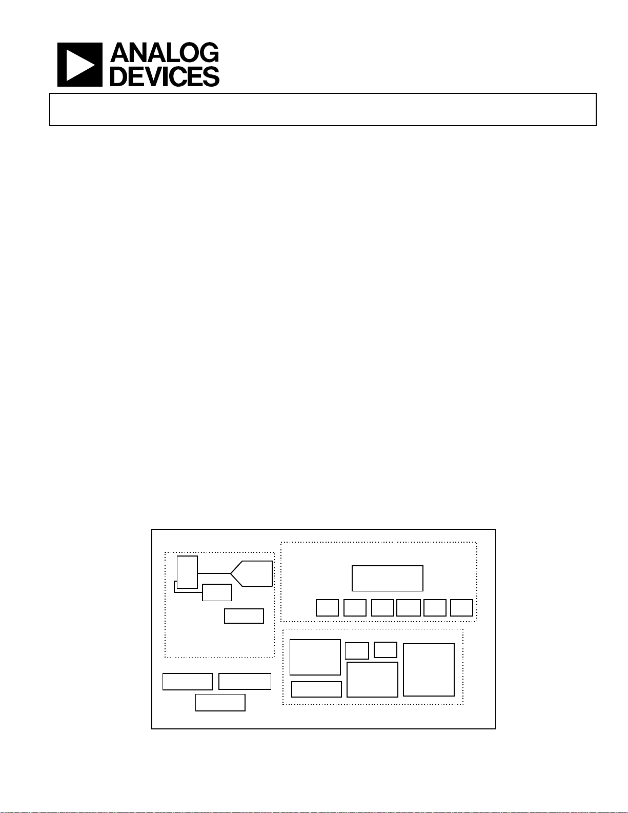
Precision Analog Microcontroller
Cortex™-M3 with ISM band Transceiver
ADuCRF101
SPI
INTERRUPT
CONTROLLER
64/128K BYTES
FLASH/EE
WAKE-UP
TIMER
LOW POWER PROCESSING
BAND GAP
REFERENCE
12/14-BIT
SAR ADC
TEMP
SENSOR
6 I/P
MUX
ADuCRF101
2xGEN PURPOSE
TIMERS
8/16K BYTES
SRAM
SERIAL
WIRE
I2C UART
PWM
GPIOS
POR
OSC
COMMUNICATIONS
PRECISION DATA
ACQUISITION
ON-CHIP PERIPHERALS
WATCHDOG
TIMER
CORTEX
M3 - CPU
LOW POWER
RF TRANSCEIVER
WIRELESS
WIRED
Rev. PrF
Information furnished by Analog
However, no responsibility is assumed by Analog Devices for its use, nor for any
infringements of patents or other rights of third parties that may result from its use.
Specifications subject to change with
or otherwise under any patent or patent rights of Analog Devices. Trademarks and
registered trademarks are the property of their respective companies.
One Technology Way, P.O. Box 9106, Norwood, MA
Tel: 781.329.4700
Fax: 781.326.8703 © 2012 Analog Devices, Inc. All rights reserved.
Preliminary Technical Data
FEATURES
Analog I/O
6-Channel 14-bit or 12-bit ADC
Single ended and differential inputs
Programmable data rate up to 842kSPS
On-Chip Voltage Reference and Temperature Sensor
Power
Supply Range: 2.2 V to 3.6 V
Power Consumption
680 nA, in power down mode, non-retained state
1.6 µA, in power down mode, MCU memory and
transceiver memory retained
190 µA / MHz, Cortex in Active mode
12.8 mA transceiver in receive mode, Cortex in power
down mode
9 to 32 mA transceiver in transmit mode, Cortex in power
down mode
RF Transceiver
Frequency bands
862 MHz to 928 MHz
431 MHz to 464 MHz
Multiple Configurations supported
Receiver sensitivity (BER)
-107.5 dBm at 38.4 kbps, 2FSK
Single ended and differential PA
Low External BOM
Microcontroller
ARM Cortex™-M3 32-bit processor
Serial Wire download and debug
External Watch crystal for wakeup timer
16 MHz internal Oscillator with 8-way Programmable
Divider
FUNCTIONAL BLOCK DIAGRAM
Memory
128k/64k Bytes Flash/EE Memory, 16k/8k Bytes SRAM
20000 cycle Flash/EE endurance
10 year Flash/EE retention
In-circuit download via Serial Wire and UART
On-Chip Peripherals
2
UA RT, I
C and SPI Serial I/O
28-Pin GPIO Port
2 General Purpose Timers
Wake -up Ti mer
Watchdog Timer
8-Channel PWM
Packages and Temperature Range
64 lead LFCSP (9mm x 9mm) package –40°C to 85°C
Tools
Low-Cost Development System
Third-Party Compiler and emulator tool Support
APPLICATIONS
Battery powered wireless sensor
Medical telemetry systems
Industrial and home automation
Asset tracking
Security systems (access systems)
Health and fitness applications
Devices is believed to be accurate and reliable.
out notice. No license is granted by implication
Figure 1. ADuCF101 Block Diagram
www.analog.com
02062-9106, U.S.A.

ADuCRF101 Preliminary Technical Data
TABLE OF CONTENTS
Features .............................................................................................. 1
Functional block diagram ................................................................ 1
General Description ......................................................................... 3
Specifications ..................................................................................... 4
Analog Front End Specifications ................................................ 4
Current Consumption Specifications ........................................ 5
RF Link Specifications ................................................................. 6
General Electrical Specifications .................................................8
Absolute Maximum Ratings ............................................................9
ESD Caution...................................................................................9
Pin Configuration and Function Descriptions ........................... 10
Outline Dimensions ....................................................................... 13
Ordering Guide .......................................................................... 13
Rev. PrF | Page 2 of 13

Preliminary Technical Data ADuCRF101
GENERAL DESCRIPTION
The ADuCRF101 is a fully integrated data acquisition solution
designed for low power wireless applications. It features an 14bit ADC, a low power Cortex™-M3 core from ARM®, a
431 MHz to 464 MHz and 862 MHz to 928 MHz RF transceiver,
and Flash/EE memory packaged in a 9 mm × 9 mm LFCSP.
The acquisition section consists of a 14 bit SAR ADC. The six
inputs can be configured as single ended or differential modes.
When configured in single ended mode, they can be used for
ratiometric measurements on sensors, powered when required
from the internal LDO. An internal battery monitor channel
and an on-chip temperature sensor are also available.
This wireless data acquisition system is designed to operate in
battery-powered applications where low power is critical. The
device can be configured in normal operating mode or different
low power modes under direct program control. In flexi mode
any peripheral can operate and wake-up the device. In
hibernate mode the internal wake-up timer remains active. In
shutdown mode only an external interrupt can wake-up the
device.
The ADuCRF101 integrates a low power Cortex-M3 core from
ARM. It is a 32-bit RISC machine, offering up to 1.25 DMIPS
peak performance. The Cortex-M3 MCU also has a flexible 14channel DMA controller supporting communication
peripherals SPI, UART and I
Flash/EE memory and 8 kB /16 kB of SRAM are also provided
on-chip.
2
C. 64 kB / 128 kB of nonvolatile
A 16 MHz on-chip oscillator generates the system clock. This
clock can be internally divided for the CPU to operate at lower
frequency for power saving reasons. A low power internal 32
kHz oscillator is available and can used to clock the timers.
There are two general-purpose timers, a wake-up timer and a
system watchdog timer.
A range of communication peripherals can be configured as
required in a specific application. These peripherals include
UA RT, I
The RF transceiver communicates in the 431 MHz to 464 MHz
and 862 MHz to 928 MHz frequency bands using multiple
configurations.
On-chip factory firmware supports in-circuit serial download
via the UART while nonintrusive emulation and program
download is also supported via the serial wire interface. These
features are incorporated into a low cost development system
supporting this precision analog microcontroller family.
The parts operate from 2.2 V to 3.6 V and are specified over an
industrial temperature range of −40°C to +85°C.
Three versions of the ADuCRF101 are available:
14-bit ADC, 128k Byte Flash and 16k Byte SRAM,
12-bit ADC, 128k Byte Flash and 16k Byte SRAM,
12-bit ADC, 64k Byte Flash and 8k Byte SRAM,
2
C, and SPI, GPIO ports, PWM and RF transceiver.
Rev. PrF| Page 3 of 13
ADuCRF101 Preliminary Technical Data
Integral Nonlinearity
±1 ±4 LSB
V
= 1.25V from internal reference
DC Code Distribution
2 8 LSB
ADC input is a DC voltage
Gain Error
±1.25
±5 LSB
Signal-to-Noise Ratio (SNR)
68 80 dB
SPECIFICATIONS
ANALOG FRONT END SPECIFICATIONS
AVDD = IOVDD = VDDBAT1 = VDDBAT2 = 2.2 V to 3.6 V, V
T
to T
MAX
, unless otherwise noted. Default ADC sampling frequency: eight acquisition clocks and ADC clock frequency of 4 MHz.
MIN
Table 1. ADC channel specifications
12-bit model 14-bit model
Parameter Typ Max Typ Max Unit Test Conditions/Comments
DC ACCURACY Single ended input mode. Applies to all
Resolution 12 14 Bits
±2 ±8 LSB V
Differential Nonlinearity ±1 ±1 LSB Guaranteed no missing code
CALIBRATED ENDPOINT ERRORS Measured using the factory-set default
Offset Error ±0.6 ±2.5 LSB
Offset Error Match ±0.25 ±1 LSB
Gain Error Match ±0.25 ±1 LSB
DYNAMIC PERFORMANCE fIN = 10 kHz sine wave.
= 1.25 V internal reference, f
REF
= 16 MHz, all specifications TA =
CORE
ADC input channels.
REF
= 1.8V from LDO
REF
values ADCOF and ADCGN.
Total Harmonic Distortion TBD TBD
Peak Harmonic or Spurious
TBD TBD
Noise (PHSN)
Channel-to-Channel Crosstalk TBD TBD Measured on adjacent channels
Table 2. ADC channel specifications
Parameter Min Typ Max Unit Test Conditions/Comments
ANALOG INPUT
Input Voltage Ranges1
Single ended input 0 V
Differential input 0 VCM ± V
V
REF
/2 V
REF
Leakage Current 100 nA
Input Capacitance 20 pF During ADC Acquisition
ADC Power-up Time 5 µs Excludes reference power up time
ON-CHIP VOLTAGE REFERENCE
Output Voltage 1.25 V
Accuracy ±5 mV Measured at TA = 25°C
Reference Temperature Co ±40 ppm/°C
Power Supply Rejection Ratio 60 dB
Output Impedance 2
Internal V
TEMPERATURE SENSOR
Power-On Time 5 ms 0.47µF external capacitor
REF
1
Indicates die temperature
Ω
Voltage Output at 25°C TBD mV
Voltage TC
Accuracy
TBD mV/°C
TBD °C MCU in low power mode
Thermal impedance TBD
1
These numbers are not production tested, but are guaranteed by design and/or characterization data at production release.
Rev. PrF | Page 4 of 13

Preliminary Technical Data ADuCRF101
mode, memory retained
CURRENT CONSUMPTION SPECIFICATIONS
AVDD = IOVDD = VDDBAT1 = VDDBAT2 = 2.2 V to 3.6 V, f
noted.
Table 3.
Parameter Min Typ Max Unit Test Conditions/Comments
CURRENT CONSUMPTION
Cortex in SHUTDOWN mode 680 nA RF transceiver in sleep mode, memory not
Cortex in HIBERNATE mode Wake up timer running from external 32kHz
RF transceiver in sleep
1.6 µA
= 16 MHz, all specifications TA = T
CORE
retained
crystal, 8kB of SRAM retained (8kB non-retained)
MAX
to T
, unless otherwise
MIN
RF transceiver in sleep
1.38 µA
mode, memory not retained
RF transceiver in receive
12.8 mA
mode
RF transceiver in transmit
9 to 32 mA
mode
Cortex active, RF transceiver
RF transceiver in PHY_ON or PHY_OFF state
active
Static current 1.8 mA
Dynamic current 190 µA/MHz
STARTUP TIME1
Cortex at Power On 40 ms
From SLEEP mode 3 to 5 FCLK FCLK is the Cortex-M3 clock or divided version of
the 16MHz oscillator.
Cortex from HIBERNATE mode 12 µs
Cortex from SHUTDOWN
40 ms
mode
Transceiver from sleep mode 562.8 µs Includes 310 µs for 26MHz crystal startup (7pF
load capacitor at T
= 25⁰C)
A
POWER SUPPLY REQUIREMENTS
Power Supply Voltage Range1 2.2 3.6 V
1
These numbers are not production tested, but are guaranteed by design and/or characterization data at production release.
Rev. PrF| Page 5 of 13

ADuCRF101 Preliminary Technical Data
bandwidth = 300 kHz
300 kHz Channel Spacing
38 dB
IF BW = 150 kHz, wanted signal: F
= 37.5 kHz,
RF LINK SPECIFICATIONS
AVDD = IOVDD = VDDBAT1 = VDDBAT2 = 2.2 V to 3.6 V, TA = T
Table 4.
Parameter Min Typ Max Unit Test Conditions / Comments
FREQUENCY RANGE
862 928 MHz
431 464 MHz
PHASE-LOCKED LOOP
Channel Frequency Resolution 396.7 Hz
Phase Noise (In-Band) -88 dBc/Hz 10 kHz offset, PA output power = 10 dBm
DATA RATE
2FSK 1 300 kbps
OOK 2.4 19.2 kbps Manchester Encoding enabled (Manchester
Data rate resolution 100 bps
TRANSMIT POWER RANGE1
Single ended PA -20 to 13.5 dBm Programmable.
Differential PA -20 to 10 dBm Programmable.
MODULATION
Deviation Frequency
100 Hz
Resolution
2FSK/GFSK INPUT SENSITIVITY,
At BER = 10−3
BIT ERROR RATE (BER)
1.0 kbps -116 dBm Frequency deviation = 10 kHz, IF filter
38.4 kbps -107.5 dBm Frequency deviation = 19.2 kHz, IF filter
300 kbps -100.5 dBm Frequency deviation = 75 kHz, IF filter
2FSK/GFSK INPUT SENSITIVITY,
At PER = 1%, packet length =20 bytes, packet
PACKET ERROR RATE (PER)
1.0 kbps -115.5 dBm Frequency deviation = 10 kHz, IF filter
38.4 kbps -106 dBm Frequency deviation = 19.2 kHz, IF filter
300 kbps -98 dBm Frequency deviation = 75 kHz, IF filter
MIN
to T
, unless otherwise noted. RF frequency = 868 MHz.
MAX
chip rate = 2 x datarate)
bandwidth = 100 kHz
bandwidth = 100 kHz
bandwidth = 300 kHz
mode
bandwidth = 100 kHz
bandwidth = 100 kHz
ADJACENT CHANNEL REJECTION
CW Interferer Wanted signal 3 dB above the input sensitivity
200 kHz Channel Spacing 38 dB IF BW = 100 kHz, wanted signal: F
300 kHz Channel Spacing 39 dB IF BW = 100 kHz, wanted signal: F
400 kHz Channel Spacing 40 dB IF BW = 200 kHz, wanted signal: F
600 kHz Channel Spacing 41 dB IF BW = 300 kHz, wanted signal: F
Rev. PrF | Page 6 of 13
level (BER = 10−3), CW interferer power level
increased until BER = 10
−3
, image calibrated
= 12.5 kHz,
DEV
DR = 50 kbps
= 25 kHz,
DEV
DR = 100 kbps
DR = 150 kbps
DEV
= 50 kHz,
DEV
DR = 200 kbps
= 75 kHz,
DEV
DR = 300 kbps

Preliminary Technical Data ADuCRF101
868 MHz
36/45
dB
Uncalibrated2/calibrated
Modulated Interferer Wanted signal 3 dB above the input sensitivity
level (BER = 10−3), modulated interferer with
the same modulation as the wanted signal;
interferer power level increased until BER =
−3
10
, image calibrated
200 kHz Channel Spacing 38 dB IF BW = 100 kHz, wanted signal: F
DR = 50 kbps
300 kHz Channel Spacing 36 dB IF BW = 100 kHz, wanted signal: F
DR = 100 kbps
300 kHz Channel Spacing 36 dB IF BW = 150 kHz, wanted signal: F
DR = 150 kbps
400 kHz Channel Spacing 34 dB IF BW = 200 kHz, wanted signal: F
DR = 200 kbps
600 kHz Channel Spacing 35 dB IF BW = 300 kHz, wanted signal: F
DR = 300 kbps
CO-CHANNEL REJECTION -4 dB Desired signal 10 dB above the input
sensitivity level (BER = 10
−3
), data rate = 38.4
kbps, frequency deviation = 20 kHz.
BLOCKING, ETSI EN 300 220
Measurement procedure as per ETSI EN 300
220-1 V2.3.1; desired signal 3 dB above the
ETSI EN 300 220 reference sensitivity level of
−99 dBm, IF bandwidth =100 kHz, data rate =
38.4 kbps, unmodulated interferer.
±2 MHz -28 dBm
±10 MHz -20.5 dBm
WIDEBAND INTERFERENCE
REJECTION
75 dB Swept from 10 MHz to 100 MHz either side of
the RF frequency
IMAGE CHANNEL ATTENUATION Measured as image attenuation at the IF filter
output, carrier wave interferer at 400 kHz
below the channel frequency, 100 kHz IF filter
bandwidth
= 12.5 kHz,
DEV
= 25 kHz,
DEV
= 37.5 kHz,
DEV
= 50 kHz,
DEV
= 75 kHz,
DEV
1
Measured as the maximum unmodulated power.
2
Measured with IMAGE_REJECT_CAL_AMPLITUDE = 0x7 and IMAGE_REJECT_CAL_PHASE = 0x16.
Rev. PrF | Page 7 of 13

ADuCRF101 Preliminary Technical Data
Watchdog Timer
Endurance2
20,000
Cycles
Logic Outputs
32.768kHz C RYSTA L
32.768 kHz crystal, for use with timers and/or RF
GENERAL ELECTRICAL SPECIFICATIONS
AVDD = IOVDD = VDDBAT1 = VDDBAT2 = 2.2 V to 3.6 V, V
T
to T
MAX
, unless otherwise noted.
MIN
Table 5.
Parameter Min Typ Max Unit Test Conditions/Comments
POWER SUPPLY MONITOR
Trip Point voltage 2 V
Trip Point accuracy 2 %
POWER-ON-RESET 1.67 V
1
Timeout Period 0 512 s Programmable
Flash/EE MEMORY
1
Data Retention3 10 Years TJ = 85°C
Digital Inputs All digital inputs, excluding LFXTAL1 and
Input Current (leakage current) 10 nA V
Input Capacitance 10 pF
Logic Inputs All Logic inputs, including LFXTAL1, excluding
VINL, Input Low Voltage 0.2 x IOVDD V
VINH, Input High Voltage 0.7 x IOVDD V
= 1.25V internal reference, f
REF
= 16 MHz, all specifications TA =
CORE
XOSC26P
= IOVDD or V
INH
V
= 0V, pull up disabled.
INL
XOSC26P
= 2.2V, pull up disabled.
INH
VOH, Output High Voltage IOVDD – 0.4 V I
VOL, Output Low Voltage 0.36 V I
source
= 1mA
sink
= 1mA
transceiver wake up controller.
Input Current (leakage current) 50 nA V
= IOVDD or V
INH
V
= 0V.
INL
= 2.2V.
INH
LFXTAL1 Input Capacitance 2 pF
LFXTAL2 Output Capacitance 2 pF
26MHz CRYSTAL
XOSC26P Input Capacitance 10 pF
XOSC26N Output Capacitance 10 pF
INTERNAL HF OSCILLATOR 16 MHz MCU clock by default
Tolerance ±3 %
INTERNAL LF OSCILLATOR 32.768 kHz
Tolerance ±20 %
MCU CLOCK DIVIDER1 1 128 8 programmable core clock dividers.
EXTERNAL CLOCK INPUT1 External MCU clock range allowed
Range 32.768 16000 kHz
1
These numbers are not production tested, but are guaranteed by design and/or characterization data at production release.
2
Endurance is qualified to 20,000 cycles as per JEDEC Std. 22 Method A117 and measured at −40°C, +25°C, and +85°C. Typical endurance at 25°C is 170,000 cycles.
3
Retention lifetime equivalent at a junction temperature (TJ) of 85°C as per JEDEC Std. 22 Method A117. Retention lifetime derates with junction temperature.
Rev. PrF | Page 8 of 13

Preliminary Technical Data ADuCRF101
θ
ABSOLUTE MAXIMUM RATINGS
TA = 25°C unless otherwise noted
Table 6.
Parameter Rating
AVDD, IOVDD, VDDBAT1 and
VDDBAT2 to GND
Digital Input Voltage to GND −0.3 V to 3.96V
Digital Output Voltage to GND −0.3 V to 3.96V
V
to GROUND −0.3 V to 3.96V
REF
Analog Inputs to GND −0.3 V to 2.1V
Operating Temperature Range –40°C to +85°C
Storage Temperature Range –65°C to +150°C
Junction Temperature 105°C
Thermal Impedance
JA
64-Pin LFCSP _VQ 25°C/W
Peak Solder Reflow Temperature
Pb-Free Assemblies (30 s) 260°C
−0.3 V to 3.96V
ESD CAUTION
The exposed paddle of the LFCSP package should be connected
to ground.
Stresses above those listed under Absolute Maximum Ratings
may cause permanent damage to the device. This is a stress
rating only; functional operation of the device at these or any
other conditions above those indicated in the operational
section of this specification is not implied. Exposure to absolute
maximum rating conditions for extended periods may affect
device reliability.
Rev. PrF | Page 9 of 13

ADuCRF101 Preliminary Technical Data
14
ADC4
ADC input channel 4
18
LVDD2
On chip LDO decoupling output. Connect a 0.47 µF capacitor to the 1.32V output to ensure core operating
33
3
2
4
9
48
16
1
7
PIN1
IDENTIFIER
1
6
4
ADuCRF101
TOP VIEW
(Not to Scale)
VDDRF1
RBIAS
VDDRF2
AVDD
2
3
4
5
6
7
8
9
10
11
12
13
14
15
VREF
RFIO_1N
RF02
VDDBAT2
1
8
1
9
2
0
ADC0
ADC1
ADC2
ADC3
ADC4
ADC5
V
D
D
V
C
O
2
1
2
2
2
3
2
4
2
5
2
6
2
7
2
8
2
9
3
0
3
1
34
35
36
37
38
39
40
41
LVDD1
S
W
D
IO
IO
V
D
D
S
W
C
L
K
V
D
D
S
Y
N
T
H
C
W
A
K
E
X
O
S
C
2
6
N
X
O
S
C
2
6
P
D
G
U
A
R
D
V
D
D
_
D
IG
1
P
1
.5
P
1
.4
P
1
.3
42
43
44
45
46
47
5
4
5
9
5
8
5
7
5
6
5
5
5
2
5
1
5
0
5
3
6
3
6
2
6
1
6
0
P
4
.2
RESET
P0.6
P0.7
IOVDD
P0.0
P0.1
P0.2
P2.4
P0.3
P2.6
P0.4
P0.5
P1.0
P1.1
P1.2
P
3
.5
P
3
.3
P
3
.4
P
3
.2
A
D
C
V
R
E
F
P
4
.7
P
4
.6
V
D
D
B
A
T
1
V
D
D
_
D
IG
2
RFIO_1P
P
4
.
3
P4.0
L
F
X
T
A
L
2
L
F
X
T
A
L
1
P
4
.5
V
C
O
G
U
A
R
D
P
4
.1
P
4
.4
G
R
O
U
N
D
L
V
D
D
2
PIN CONFIGURATION AND FUNCTION DESCRIPTIONS
Figure 8. 64-Lead LFCSP_VQ Pin Configuration
Table 7. Pin Function Descriptions
Pin
Mnemonic Description
No.
1 VDDRF1 Voltage Regulator output for RF circuits. A 220 nF capacitor should be placed between this pin and ground for
regulator stability and noise rejection.
2 RBIAS External bias resistor. A 36 kΩ resistor with 2% tolerance should be used.
3 VDDRF2 Voltage Regulator output for RF block. A 220 nF capacitor should be placed between this pin and ground for
regulator stability and noise rejection.
4 RFIO_1P LNA Positive Input in Receive Mode. Differential PA Positive Output in Transmit Mode.
5 RFIO_1N LNA Negative Input in Receive Mode. Differential PA Negative Output in Transmit Mode.
6 RF02 Single ended PA output.
voltage is stable.
regulator stability and noise rejection.
voltage is stable
Rev. PrF | Page 10 of 13
7 VDDVBAT2 Battery Terminal, supply for the LDOs used in the RF section of the transceiver.
8 AVDD Battery terminal, Supply for analog circuits such as ADC and ADC internal reference, POR, PSM and LDOs.
9 VREF Internal 1.25V ADC reference. A 0.47 µF capacitor between this pin and ground is required.
10 ADC0 ADC input channel 0
11 ADC1 ADC input channel 1
12 ADC2 ADC input channel 2
13 ADC3 ADC input channel 3
15 ADC5 ADC input channel 5
16 LVDD1 On chip LDO decoupling output. Connect a 0.47 µF capacitor to the 1.8V output to ensure core operating
17 VDDVCO Voltage Regulator output for VCO. A 220 nF capacitor should be placed between this pin and ground for
19 SWDIO Serial Wire bi-directional data
20 GND Ground pin, should be connected to the PADDLE.
21 IOVDD Battery terminal, General Purpose IO supply.

Preliminary Technical Data ADuCRF101
28
DGUARD
Internal Guard, Screen for Digital Cells, should be connected to VDD_DIG1.
29
VDD_DIG 1
Voltage Regulator output for Digital. A 220 nF capacitor should be placed between this pin and ground for
/ECLKOUT
Pin
Mnemonic Description
No.
22 SWCLK Serial Wire debug clock
23 VCOGUARD Guard, screen for VCO, should be connected to VDDVCO.
24 VDDSYNTH Voltage Regulator output for Synthesizer. A 220 nF capacitor should be placed between this pin and ground for
regulator stability and noise rejection.
25 CWAKE External capacitor for wake up control. A 150 nF capacitor should be placed between this pin and ground.
26 XOSC26P The 26MHz reference crystal should be connected between this pin and XOSC26N.
27 XOSC26N The 26MHz reference crystal should be connected between this pin and XOSC26P.
regulator stability and noise rejection.
30 P1.5/IRQ6/I2CSD
A/PWM7
31 P1.4/IRQ5/I2CSC
L/PWM6
32 P1.3/PWM5 General Purpose Input and Output Port 1.3/PWM channel 5.
33 P1.2/PWM4 General Purpose Input and Output Port 1.2/PWM channel 4.
34 P1.1/PORB/ TXD
/PWM3
35 P1.0/RXD/IRQ4/
MOSI /PWM2
36
37
CS2
P0.5/
/ECLKIN
CS1
P0.4/
General Purpose Input and Output Port 1.5/External Interrupt 6/I2C Serial Data/PWM channel 7.
General Purpose Input and Output Port 1.4/External Interrupt 5/I2C Serial Clock/PWM channel 6.
General Purpose Input and Output Port 1.1/POR output/ UART TXD/ PWM channel 3.
General Purpose Input and Output Port 1.0/UART RXD/ External Interrupt 4/ SPI1 Master Out Slave In Pin
(MOSI)/PWM channel 2.
General Purpose Input and Output Port 0.5/SPI1 Chip Select 2/External Clock Input
General Purpose Input and Output Port 0.4/SPI1 Chip Select 1/External Clock Output.
38 P2.6/GP0 General Purpose Input and Output Port 2.6
39
P0.3/IRQ1/
/ADCCONVST/P
WM1
40 P2.4/IRQ8 General Purpose Input and Output Port 2.4/ External Interrupt 8
41 P0.2/MOSI/PWM0 General Purpose Input and Output Port 0.2/SPI1 Master Out Slave In Pin (MOSI)/PWM channel 0.
42 P0.1/SCLK General Purpose Input and Output Port 0.1/SPI1 Serial Clock
43 P0.0/MISO General Purpose Input and Output Port 0.0/SPI1 Master In Slave Out Pin (MISO)
44 IOVDD General Purpose I/O supply. Connect to the battery terminal
45
P0.7/IRQ3/
/CTS
46 P0.6, BOOT/
IRQ2/
RTS/PWM0
47 RESET Active Low. A low signal on this pin for 24 system clocks will cause the part to reset.
48 P4.0/PWM0 General Purpose Input and Output Port 4.0/PWM channel 0.
49 P4.1/PWM1 General Purpose Input and Output Port 4.1/PWM channel 1.
50 P4.2/PWM2 General Purpose Input and Output Port 4.2/PWM channel 2.
51 P4.3/PWM3 General Purpose Input and Output Port 4.3/PWM channel 3.
52 P4.4/PWM4 General Purpose Input and Output Port 4.4/PWM channel 4.
53 P4.5/PWM5 General Purpose Input and Output Port 4.5/PWM channel 5.
54 LFXTAL1 32.768kHz watch crystal output for WU timers.
55 LFXTAL2 32.768kHz watch crystal input for WU timers.
56 VDD_DIG2 Voltage Regulator output for Digital section of the transceiver. A 220 nF capacitor should be placed between
57 VDDBAT1 Battery Terminal, supply for the digital section of the transceiver and GPIOs.
58 P4.6/PWM6 General Purpose Input and Output Port 4.6/PWM channel 6.
59 P4.7/PWM7 General Purpose Input and Output Port 4.7/PWM channel 7.
CS3
CS0
CS4
/
General Purpose Input and Output Port 0.3/External Interrupt 1/SPI1 Chip Select 0/ADC convert start/PWM
channel 1.
General Purpose Input and Output Port 0.7/ External Interrupt 3 / SPI1 Chip Select 4/ UART hand shake.
General Purpose Input and Output Port 0.6, BOOT pin / External Interrupt 2/ SPI1 Chip Select 3 / UART hand
shake/PWM channel 0.
this pin and ground for regulator stability and noise rejection.
Rev. PrF | Page 11 of 13

ADuCRF101 Preliminary Technical Data
Pin
Mnemonic Description
No.
60 ADCVREF Transceiver’s ADC Reference Output. A 220 nF capacitor should be placed between this pin and ground for
adequate noise rejection.
61 P3.2/PWMSYNC General Purpose Input and Output Port 3.2/PWM synchronisation.
62 P3.3/PWMTRIP General Purpose Input and Output Port 3.3/PWM safety cut off.
63 P3.4 General Purpose Input and Output Port 3.4.
64 P3.5 General Purpose Input and Output Port 3.5.
65 PADDLE The exposed package paddle should be soldered to a metal pad on the PCB, and connected to ground.
Rev. PrF | Page 12 of 13

Preliminary Technical Data ADuCRF101
OUTLINE DIMENSIONS
Figure 2. 64-Lead Frame Chip Scale Package [LFCSP_VQ]
9 mm x 9 mm Body, Very Thin Quad
Dimensions shown in millimeters
(CP-64-1)
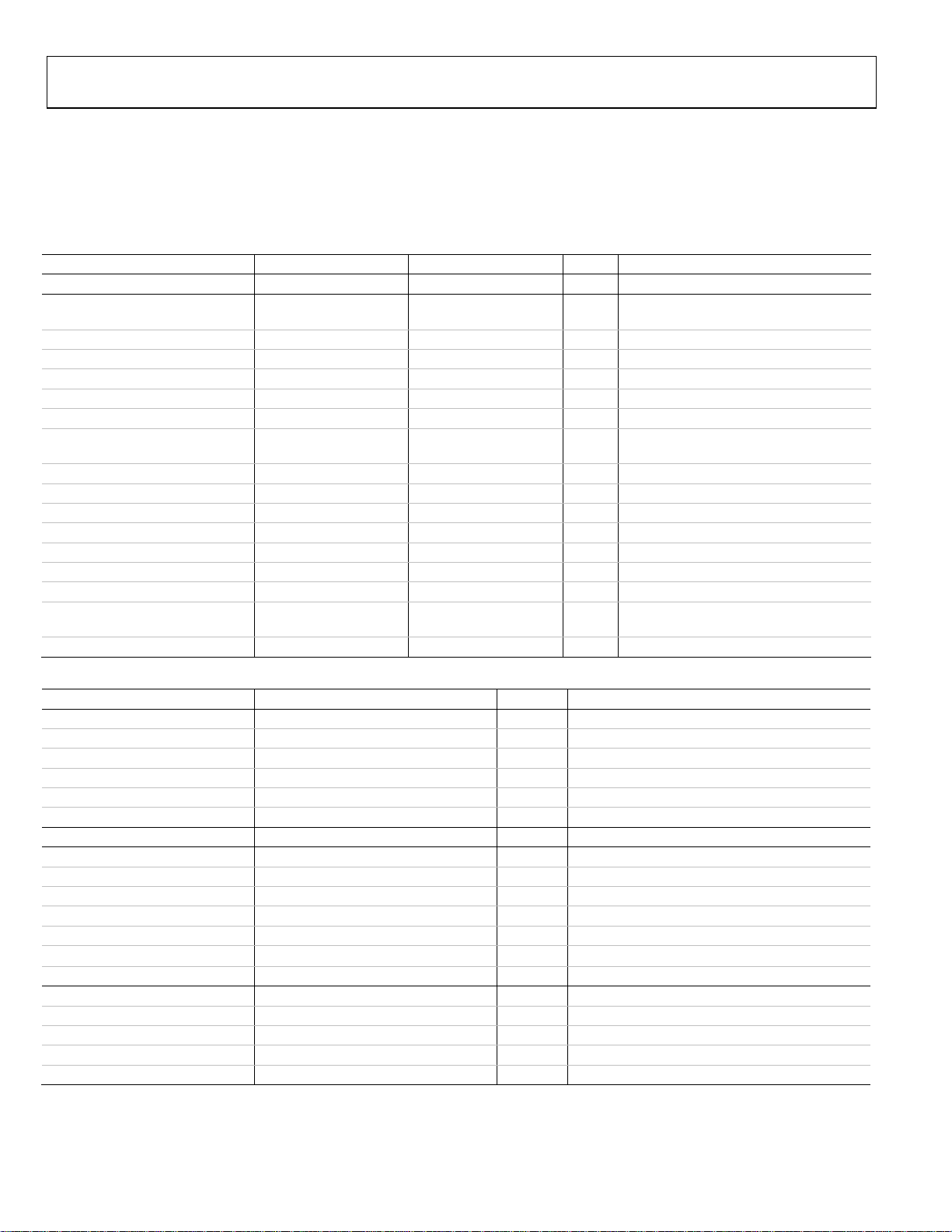
ORDERING GUIDE
Model Temperature Range Description Package Option
-40⁰C to 85⁰C 14-bit ADC, 128k Byte Flash and 16k Byte SRAM 64-lead LFCSP
-40⁰C to 85⁰C 12-bit ADC, 128k Byte Flash and 16k Byte SRAM 64-lead LFCSP
-40⁰C to 85⁰C 12-bit ADC, 64k Byte Flash and 8k Byte SRAM 64-lead LFCSP
-40⁰C to 85⁰C Evaluation board for 433MHz operation n/a
-40⁰C to 85⁰C Evaluation board for 868/915MHz operation n/a
I2C refers to a communications protocol originally developed by Philips Semiconductors (now NXP Semiconductors).
©2012 Analog Devices, Inc. All rights reserved. Trademarks and
registered trademarks are the proper ty of their respective owners.
PR09464-0-3/12(PrF)
Rev. PrF | Page 13 of 13
 Loading...