

Constant-Frequency, Current-Mode
www.BDTIC.com/ADI
FEATURES
92% efficiency (no sense resistor required)
±1.0% initial accuracy
IC supply voltage range: 2.9 V to 5.5 V
Power-input voltage as low as 1.0 V
Capable of high supply input voltage (>5.5 V)
with an e
UVLO and 35 mA shunt regulator
V
IN
External slope compensation with 1 resistor
Programmable operating frequency
(100 k
Lossless current sensing for switch-node voltage <30 V
Resistor current sensing for switch-node voltage >30 V
Synchronizable to external clock
Current-mode operation for excellent line and load transient
r
esponses
10 μA shutdown current
Current limit and thermal overload protection
Soft start in 2048 clock cycles
APPLICATIONS
APD bias
Portable electronic equipment
Isolated dc/dc converter
Step-up/step-down dc/dc converter
LED driver for laptop computer and navigation system
LCD backlighting
GENERAL DESCRIPTION
The ADP1621 is a fixed-frequency, pulse-width modulation
(PWM), current-mode, step-up converter controller. It drives an
external n-channel MOSFET to convert the input voltage to a
higher output voltage. The ADP1621 can also be used to drive
flyback, SEPIC, and forward converter topologies, either isolated
or nonisolated.
The ADP1621 eliminates the use of a current-sense power
sistor by measuring the voltage drop across the on resistance
re
of the n-channel MOSFET. This technique, allowed up to a
maximum voltage of 30 V at the switch node, maximizes
efficiency and reduces cost. For switch-node voltages higher than
30 V or for more accurate current limiting, the CS pin can be
connected to a current-sense resistor in the source of the MOSFET.
The slope compensation is implemented by an external resistor,
allowing a wide range of external components (inductors and
MOSFETs), and can be chosen for various switching frequencies
and input and output voltages.
The ADP1621 supply input voltage range is 2.9 V to 5.5 V, although
hig
her input voltages are possible with the use of a small-signal
Rev. A
Information furnished by Analog Devices is believed to be accurate and reliable. However, no
responsibility is assumed by Anal og Devices for its use, nor for any infringements of patents or ot her
rights of third parties that may result from its use. Specifications subject to change without notice. No
license is granted by implication or otherwise under any patent or patent rights of Analog Devices.
Trademarks and registered trademarks are the property of their respective owners.
xternal NPN or a resistor
Hz to 1.5 MHz) with 1 resistor
Step-Up DC/DC Controller
ADP1621
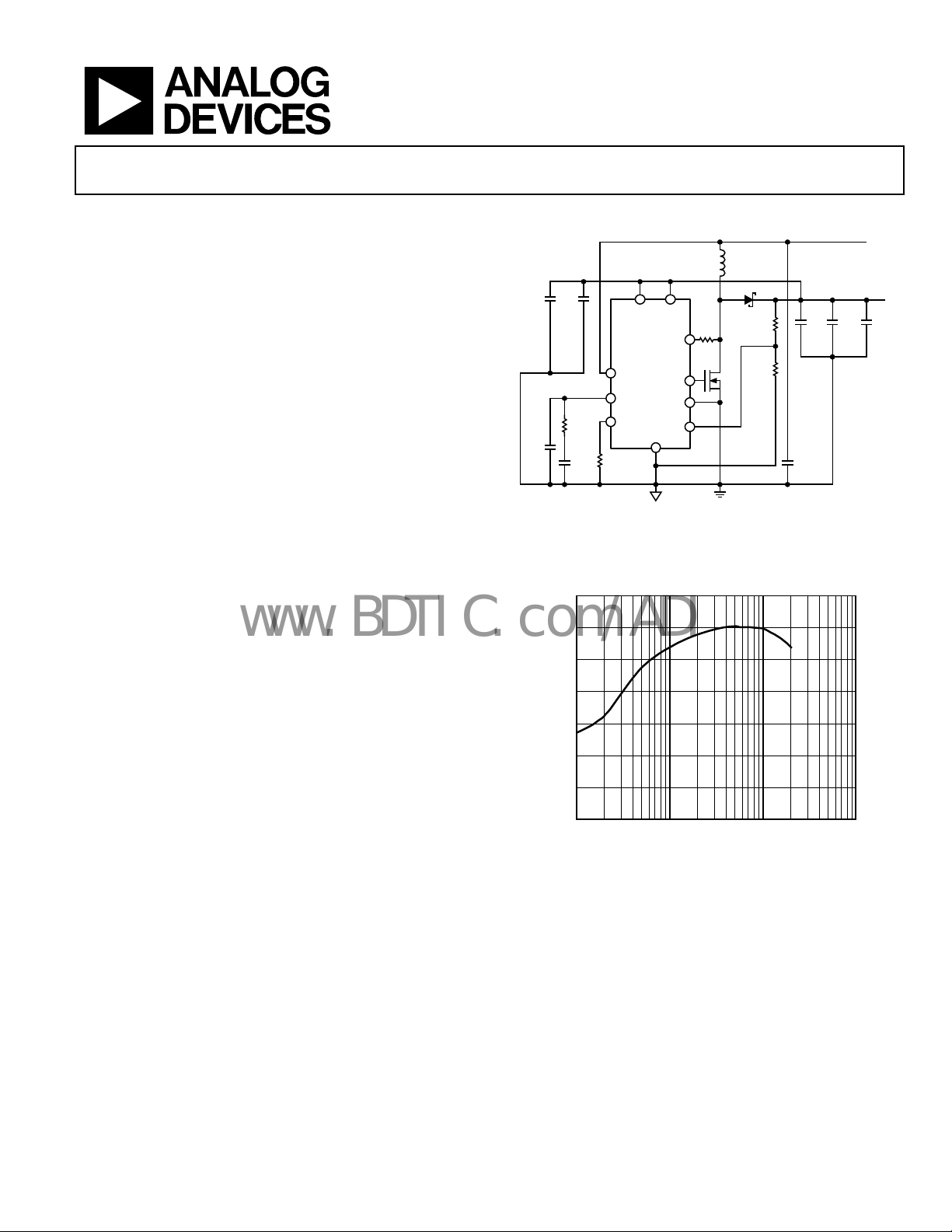
TYPICAL APPLICATION CIRCUIT
L1
4.7µH
D1
C3
C4
1µF
0.1µF
10V
10V
SDSN
COMP
R
COMP
COMP
R
FREQ
31.6kΩ
1%
FREQ
9.09kΩ
C2
120pF
C
1.8nF
f
= 600kHz
OSC
C1 = MURATA GRM31CR60J476M
C
= SANYO POSCAP 6TPE150M
OUT3
L1 = TOKO FDV0630-4R7M
Figure 1. High Efficiency Output Bo
3.3 V Input, 5 V Output (Bootstrapped)
100
90
80
70
60
EFFICIENCY (%)
50
40
30
0.01 10
Figure 2. Efficiency of Circuit Shown in Figure 1
NPN pass transistor or a single resistor. The voltage of the
power input can be as low as 1 V for fuel cell applications. The
switching frequency is set by an external resistor over a range of
100 kHz to 1.5 MHz and can be synchronized to an external
clock by using the SDSN pin. The shutdown quiescent current is
less than 10 μA. The ADP1621 has a thermal shutdown feature
that shuts down the gate driver when the junction temperature
reaches approximately 150°C. The internal soft start circuit limits
inrush current at startup. The ADP1621 is available in the 10-lead
MSOP lead-free package and is specified over the −40°C to +125°C
junction temperature range.
One Technology Way, P.O. Box 9106, Norwood, MA 02062-9106, U.S.A.
Tel: 781.329.4700 www.analog.com
Fax: 781.461.3113 ©2006 Analog Devices, Inc. All rights reserved.
IN
PIN
CS
ADP1621
GATE
PGND
FB
GND
AGND
M1 = VISHAY Si7882DP
D1 = VISHAY SSA33L
0.1 1
LOAD CURRENT (A)
R
35.7kΩ
S
80Ω
11.5kΩ
M1
ost Converter in Lossless Mode,
V
= 3.3V
IN
R1
1%
C
OUT1
1µF
10V
R2
1%
C1
47µF
6.3V
C
10µF
10V
OUT2
V
= 5V
OUT
1A
C
OUT3
150µF
6.3V
×2
06090-001
06090-042

ADP1621
www.BDTIC.com/ADI
TABLE OF CONTENTS
Features.............................................................................................. 1
Applications....................................................................................... 1
General Description ......................................................................... 1
Typical Application Circuit ............................................................. 1
Revision History ............................................................................... 2
Specifications..................................................................................... 3
Absolute Maximum Ratings............................................................ 5
Thermal Resistance ...................................................................... 5
ESD Caution.................................................................................. 5
Simplified Block Diagram ............................................................... 6
Pin Configuration and Function Descriptions............................. 7
Typical Performance Characteristics ............................................. 8
Theory of Operation ...................................................................... 12
Control Loop............................................................................... 12
Current-Sense Configurations.................................................. 12
Current Limit.............................................................................. 13
Undervoltage Lockout ............................................................... 13
Shutdown..................................................................................... 13
Soft Start ...................................................................................... 13
Internal Shunt Regulators.......................................................... 13
Setting the Oscillator Frequency and Synchronization
Frequency .................................................................................... 13
Application Information: Boost Converter................................. 14
Duty Cycle................................................................................... 14
Setting the Output Voltage........................................................ 14
Inductor Current Ripple............................................................ 14
Inductor Selection...................................................................... 14
Input Capacitor Selection.......................................................... 15
Output Capacitor Selection....................................................... 15
Diode Selection........................................................................... 15
MOSFET Selection..................................................................... 16
Loop Compensation .................................................................. 16
Slope Compensation.................................................................. 17
Current Limit.............................................................................. 18
Light Load Operation ................................................................ 18
Recommended Component Manufacturers........................... 19
Layout Considerations................................................................... 20
Efficiency Considerations ............................................................. 21
Examples of Application Circuits................................................. 22
Standard Boost Converter—Design Example........................ 22
Bootstrapped Boost Converter................................................. 23
SEPIC Converter Circuit........................................................... 27
Low Voltage Power-Input Circuit ............................................ 27
LED Driver Application Circuits ............................................. 28
Related Parts.................................................................................... 30
Outline Dimensions....................................................................... 31
Ordering Guide .......................................................................... 31
REVISION HISTORY
12/06—Rev. 0 to Rev. A
Changes to Table 1............................................................................ 3
Changes to Table 2............................................................................ 5
Added Table 3.................................................................................... 5
Changes to Table 5.......................................................................... 19
Changes to Ordering Guide.......................................................... 31
7/06—Revision 0: Initial Version
Rev. A | Page 2 of 32
ADP1621
www.BDTIC.com/ADI
SPECIFICATIONS
VIN = 5 V, R
Table 1.
Parameter Symbol Conditions Min Typ Max Unit
MAIN CONTROL LOOP
Internal Soft Start Time tSS 2048 Cycles
PIN Supply Voltage
IN Supply Voltage
Shunt Regulation Voltage V
I
Shunt Resistance R
Current into PIN = 8 mA to 12 mA 7 Ω
IN Quiescent Current IIN V
IN Shutdown Current VIN = 2.9 V to 5.5 V, SDSN = GND 1 10 μA
PIN Supply Current I
Static Mode, No Switching VFB = 1.3 V, V
Shutdown Mode SDSN = GND 1 10 μA
Undervoltage Lockout Threshold at
IN Pin
FB Regulation Voltage VFB T
1.197 1.215 1.233 V
FB Input Current IFB V
Line Regulation
2.9 V ≤ VIN ≤ 5 V, TJ = −40°C to +125°C 0.02 0.072 %/V
Load Regulation
Error Amplifier Transconductance gm 300 μS
COMP Zero-Current Threshold V
COMP Clamp High Voltage V
T
Current-Sense Amplifier Gain n 7.5 9.5 11.5 V/V
Peak Slope-Compensation Current at
CS Pin
CS Pin Leakage Current I
Shutdown Time tSD SDSN pin from high to low or left floating 50 μs
Thermal Shutdown Threshold
Thermal Shutdown Hysteresis
OSCILLATOR
Oscillator Frequency Range
Oscillator Frequency f
Oscillator Frequency Tempco f
SDSN Input Level Threshold V
SDSN Threshold Hysteresis −0.19 V
SDSN Internal Pull-Down Resistor R
Synchronization Minimum Pulse Width t
Synchronization Maximum Pulse Width t
Synchronization Frequency f
GATE Minimum On Time t
GATE Minimum Off Time t
Maximum Duty Cycle
Recommended Maximum
Synchronized Frequency Ratio
= 100 kΩ, f
FREQ
4
= 200 kHz, TJ = −40°C to 125°C, unless otherwise noted.
OSC
1
1
2
3
5
5
6
6, 7
6, 8
V
2.9 V
PIN
VIN 2.9 V
I
SHUNT
Current into IN = 8 mA to 12 mA 13 Ω
SHUNT
PIN
V
V
UVLO
V
= 3 mA, I
IN
= 3 mA, I
IN
= 2.9 V to 5.5 V, VFB = 1.215 V 1.8 3 mA
IN
rising 2.2 2.5 2.8 V
UVLO
hysteresis −80 mV
UVLO
= 25°C 1.203 1.215 1.227 V
A
= 1.215 V, TA = 25°C −75 +25 +75 nA
FB
= 3 mA, TA = 25°C 5.4 5.6 5.7 V
PIN
= 3 mA 5.2 5.6 6.0 V
PIN
COMP
< V
, GATE = 0 V 1 10 μA
COMP,ZCT
SHUNT
SHUNT
V
V
∆VFB/∆VIN 2.9 V ≤ VIN ≤ 5 V, TJ = −40°C to +85°C 0.02 0.06 %/V
∆VFB/∆V
COMP,ZCT
COMP,CLAMP
I
SC,PK
CS,LEAK
T
TMSD
COMP
V
= 1.4 V to 1.5 V −1 −0.1 %
COMP
0.85 1.0 1.15 V
TJ = −40°C to +85°C 1.9 2.0 2.1 V
= −40°C to +125°C 1.9 2.0 2.2 V
J
= 0 V to 100 mV maximum
V
CS
across R
V
= 30 V (GATE low) 5 μA
CS
(GATE high)
S
55 70 85 μA
150 °C
−10 °C
f
100 1500 kHz
OSC
R
OSC
±0.06 %/°C
OSC,TC
SDSN,THRESH
SDSN
SYNC,MIN
SYNC,MAX
SYNC
ON,MIN
OFF,MIN
D
MAX
f
SYNC/fOSC
VIN = V
100 kΩ
V
V
110 1800 kHz
V
V
f
f
= 65 kΩ, TA = 25°C 255 325 395 kHz
FREQ
= 5 V 1.5 1.7 1.9 V
PIN
= 0 V to VIN 45 100 ns
SDSN
= 0 V to VIN 0.8/f
SDSN
= 1.215 V, V
FB
= 1.215 V, V
FB
= 200 kHz, R
SW
= 200 kHz, R
OSC
= 1.0 V 180 215 ns
COMP
= 2.0 V 190 230 ns
COMP
= 100 kΩ 93 97 %
FREQ
= 100 kΩ, f
FREQ
= fSW 1.1 1.2 1.4
SYNC
ns
SYNC
Rev. A | Page 3 of 32

ADP1621
www.BDTIC.com/ADI
Parameter Symbol Conditions Min Typ Max Unit
GATE DRIVER
GATE Rise Time
GATE Fall Time
1
The maximum input voltage is the shunt regulation voltage, which is typically 5.5 V and can range from 5.3 V to 6.0 V over the specified temperature range.
2
The ADP1621 is tested in a feedback servo loop, which servos VFB to the internal reference voltage. The voltage change in FB is measured while VIN is changed from
2.9 V to 5 V. The line regulation is calculated by (∆VFB/VFB) × 100%/∆VIN.
3
The ADP1621 is tested in a feedback servo loop, which servos VFB to the internal reference voltage, and V
(1.0 V ≤ V
4
The peak slope-compensation current at the CS pin is typically 70 μA, and effectively clamped at 116 mV. Thus, RS should not exceed 1.6 kΩ (116 mV/70 μA).
5
Guaranteed by design for thermal shutdown. When the thermal junction temperature of the ADP1621 reaches approximately 150°C, the ADP1621 goes into thermal
COMP
shutdown and the GATE voltage is pulled low. When the junction temperature drops below about 140°C, the soft start sequence is initiated and the ADP1621 resumes
normal operation.
6
f
is the natural oscillation frequency, f
OSC
7
Guaranteed by design and bench characterization.
8
To ensure proper synchronization operation, set the synchronization frequency, f
be synchronized to as high as 1.8 MHz, the peak slope-compensation current decreases at higher synchronization frequencies. It is recommended that the maximum
f
be less than 1.4× of f
SYNC
Compensation section in the Application Information: Boost Converter section).
9
GATE rise and fall times are measured from 10% to 90% levels.
9
≤ 2.0 V).
9
is the synchronization frequency, and fSW is the switching frequency. If synchronization is used, then fSW = f
SYNC
and should not exceed 1.8 MHz. The slope-compensation resistor, RS, should be chosen for the synchronization frequency (see the Slope
OSC
tR C
tF C
= 3.3 nF 17 ns
GATE
= 3.3 nF 13 ns
GATE
, to 1.2× of the free-running frequency, f
SYNC
is forced from 1.4 V to 1.5 V. The V
COMP
. Although the switching frequency can
OSC
range is
COMP
; otherwise, fSW = f
SYNC
OSC
.
Rev. A | Page 4 of 32
ADP1621
www.BDTIC.com/ADI
ABSOLUTE MAXIMUM RATINGS
Table 2.
Parameter Rating
IN to GND −0.3 V to V
FB, COMP, SDSN, FREQ, GATE to GND −0.3 V to (VIN + 0.3 V)
CS to GND −5 V to +33 V
PIN to PGND −0.3 V to V
Supply Current into IN 25 mA
Supply Current into PIN 35 mA
Storage Temperature Range −55°C to +150°C
Junction Operating Temperature Range1 −55°C to +150°C
Junction Storage Temperature Range −55°C to +150°C
Lead Temperature (Soldering, 10 sec) 300°C
Package Power Dissipation1 (T
1
In applications where high power dissipation and poor package thermal
resistance are present, the maximum ambient temperature may need to be
derated. Maximum ambient temperature (TA,MAX) is dependent on the
maximum operating junction temperature (TJ,MAX = 150oC), the maximum
power dissipation of the device in the application (PD,MAX), and the junctionto-ambient thermal resistance of the package in the application (θ
by the following equation: T
A,MAX = TJ,MAX --- (θJA x PD,MAX).
J,MAX
− TA)/θJA
SHUNT
SHUNT
JA), is given
Stresses above those listed under Absolute Maximum Ratings
may cause permanent damage to the device. This is a stress
rating only; functional operation of the device at these or any
other conditions above those indicated in the operational
section of this specification is not implied. Exposure to absolute
maximum rating conditions for extended periods may affect
device reliability.
Absolute maximum ratings apply individually only, not in
mbination. Unless otherwise specified, all other voltages are
co
referenced to GND.
THERMAL RESISTANCE
θJA is specified for the worst-case conditions, that is, a device
soldered in a circuit board for surface-mount packages.
Table 3. Thermal Resistance
Package Type θJA Unit
10-lead MSOP on a 2-layer PCB 200 °C/W
10-lead MSOP on a 4-layer PCB 172 °C/W
Junction-to-ambient thermal resistance of the package is based
on modeling and calculation using 2-layer and 4-layer boards,
and natural convection. The junction-to-ambient thermal
resistance is application- and board-layout dependent. In
applications where high maximum power dissipation exists,
attention to thermal dissipation issues in board design is
required.
ESD CAUTION
Rev. A | Page 5 of 32
ADP1621
www.BDTIC.com/ADI
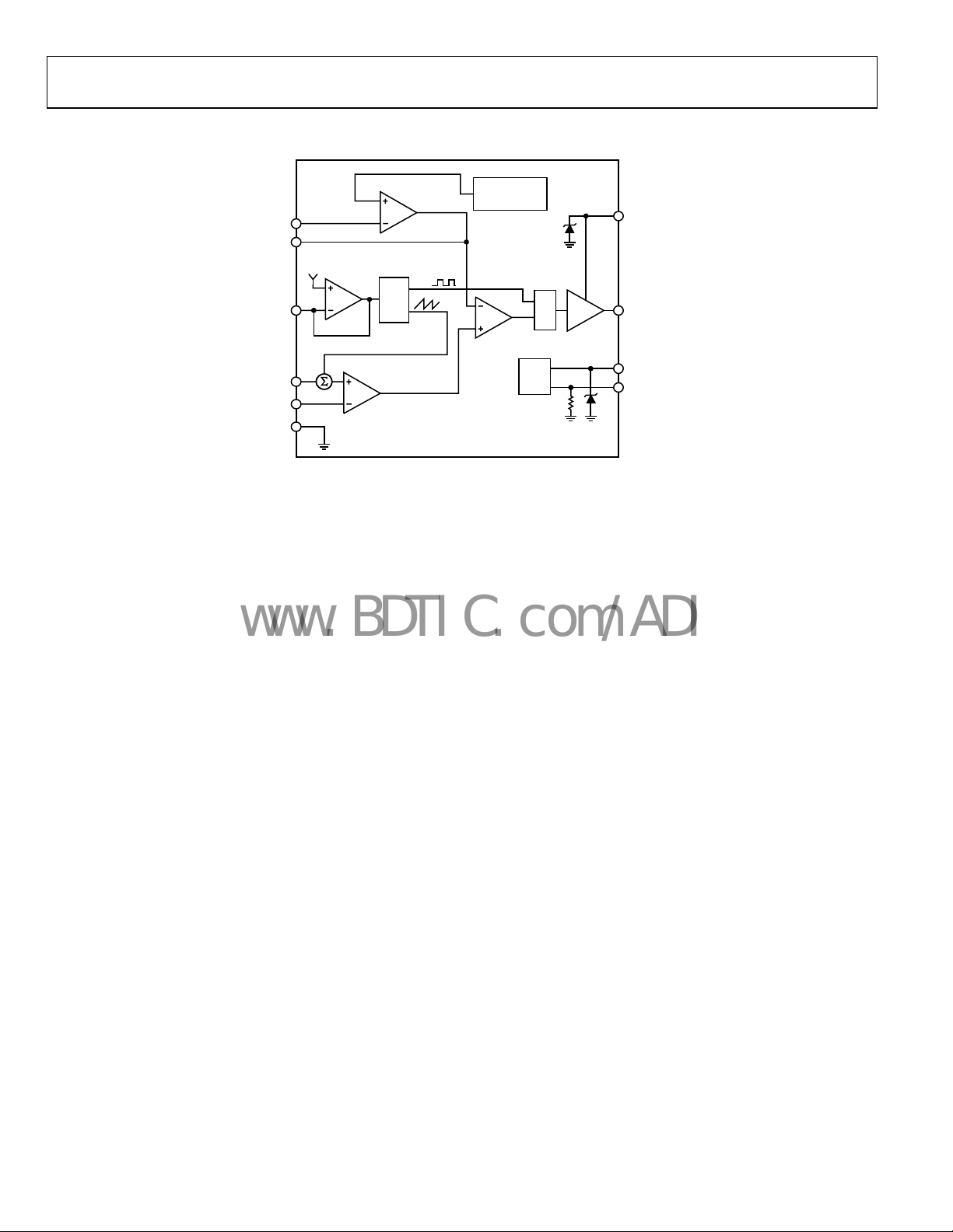
SIMPLIFIED BLOCK DIAGRAM
FB
COMP
V
OSC
1.4V
FREQ
+
+
CS
PGND
GND
V
REF
1.215V
ERROR
AMPLIFIER
g
m
SET
OSC
SLOPE
COMP
n
SOFT START
(2048 CYCLES)
PWM
COMPARATOR
Figure 3. ADP1621 Simplified Block Diagram
UVLO
5.5V
S
R
100kΩ
ADP1621
GATE
DRIVER
5.5V
PIN
GATE
IN
SDSN
06090-002
Rev. A | Page 6 of 32

ADP1621
C
www.BDTIC.com/ADI
PIN CONFIGURATION AND FUNCTION DESCRIPTIONS
Table 4. Pin Function Descriptions
Pin No. Mnemonic Description
1 SDSN
Shutdown and Synchronization Input. Tur
If SDSN is left floating or when the SDSN is pulled low, the ADP1621 goes into shutdown after 50 μs. If synchronization is
needed, synchronize the switching frequency to an external clock by connecting the external clock to the SDSN
pin. An internal 100 kΩ pull-down resistor is connected from SDSN to GND.
2 GND Ground.
3 COMP
Regulation Control Compensation Node. COMP is the output of
Connect a series RC from COMP to GND to compensate the regulator. The nominal voltage range for this pin is
1.0 V to 2.0 V.
4 FB
Feedback Input. FB is the input to the in
through a resistive voltage divider. The ratio of the voltage divider sets the output voltage. The regulation voltage
at FB is nominally 1.215 V.
5 FREQ
Frequency Control Input. Connect a resistor from FREQ t
between 100 kHz and 1.5 MHz. The nominal voltage of this pin is 1.4 V.
6 PGND
Power Ground Input. PGND is the ground return for the inter
current-sense amplifier. Connect PGND to GND as close to the ADP1621 as possible.
7 GATE
Gate Driver Output. The maximum gate driver output is equal t
external n-channel power MOSFET. Connect GATE to the gate of the MOSFET.
8 PIN
Power Input. PIN powers the gate driver output. An internal 5.5 V shunt regulat
PIN to PGND with a 0.1 μF or greater capacitor.
9 CS
Current-Sense Input. CS is the positive input of the current-se
the CS pin increases linearly from 0 V to a maximum of 116 mV, and the nominal peak slope-compensation output
current is 70 μA. When GATE is off, the CS function is disabled. For current sensing in lossless mode, connect CS to
the drain of the power MOSFET. The absolute maximum voltage at CS is 33 V. For higher accuracy current sensing
or higher switch-node voltages, connect CS to a current-sense power resistor in the source of the power MOSFET.
In both sensing methods, it is required to add a slope-compensation resistor, R
in the inductor current for duty cycles greater than 50%. However, it is recommended to add R
because load transients can momentarily cause the duty cycle to be greater than 50%, even when the steady-
state duty cycle is less than 50%.
10 IN
Input Voltage. IN powers the ADP1621 internal circuitry. An in
Bypass IN to GND with a 0.1 μF or greater capacitor.
1
SDSN
GND
2
OMP
FREQ
ADP1621
3
TOP VIEW
(Not to Scale)
FB
4
5
Figure 4. Pin Configuration
n the ADP1621 on by driving SDSN high; turn it off by driving SDSN low.
ternal transconductance error amplifier. Drive FB from the output voltage
10
IN
CS
9
PIN
8
GATE
7
6
PGND
06090-003
the internal transconductance error amplifier.
o GND to set the free-running switching frequency
nal gate driver and the negative input of the internal
o the PIN voltage. GATE drives the gate of the
or is connected to this pin. Bypass
nse amplifier. When GATE is turned on, the voltage at
, to the CS pin to achieve stability
S
ternal 5.5 V shunt regulator is connected to this pin.
for all duty cycles
S
Rev. A | Page 7 of 32
ADP1621
www.BDTIC.com/ADI
TYPICAL PERFORMANCE CHARACTERISTICS
100
92
90
80
70
60
EFFICIENCY (%)
50
40
30
0.01 10
0.1 1
LOAD CURRENT (A)
TA = 25°C
f
= 220kHz
SW
V
= 3.3V
IN
V
= 5V
OUT
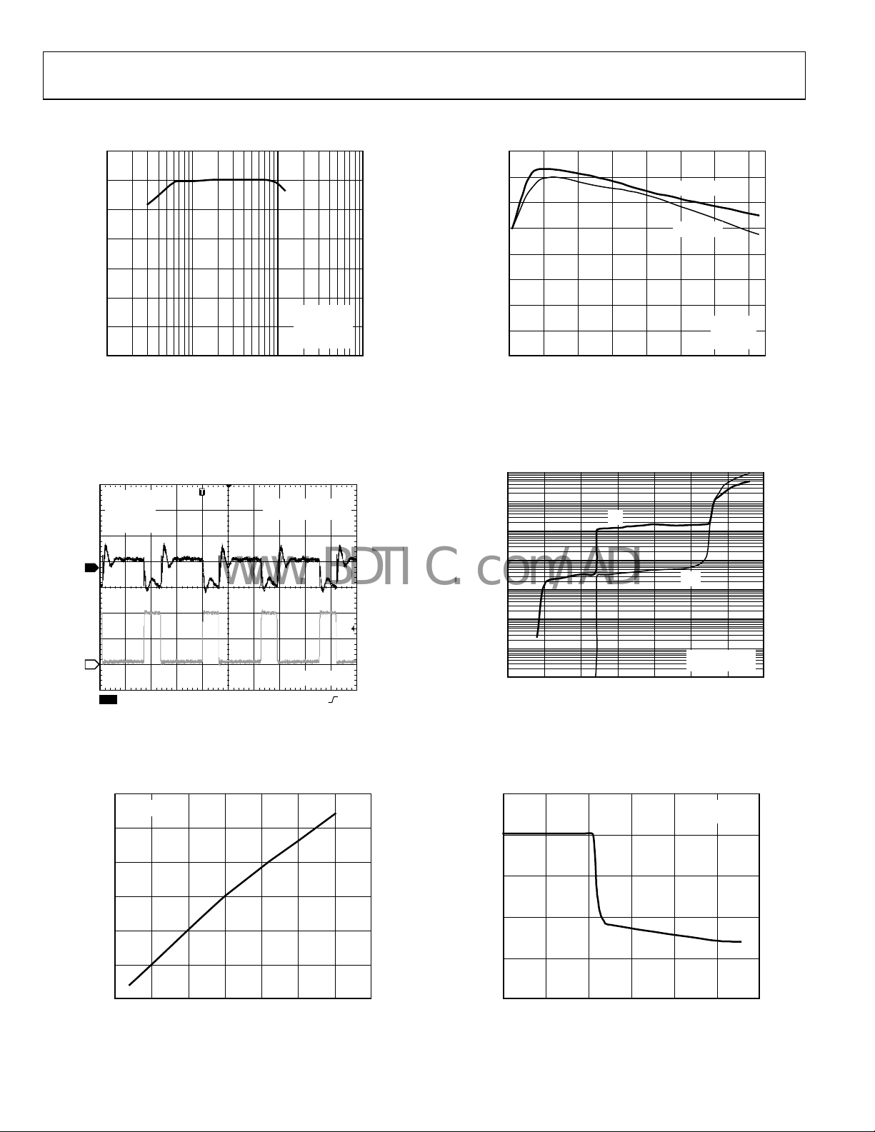
Figure 5. Efficiency vs. Load Current
1
TA = 25°C
= 3.3V
V
IN
= 5V
V
OUT
LOAD = 1A
V
RIPPLES @ 5V
OUT
AC-COUPLED
91
90
89
88
87
EFFICIENCY (%)
86
85
84
100
300 500 700 900 1100 1300 1500
06090-004
SWITCHING FREQUENCY (kHz)
LOAD = 0.5A
LOAD = 1A
TA = 25°C
V
V
= 3.3V
IN
OUT
= 5V
06090-007
Figure 8. Efficiency vs. Switching Frequency
100
10
1
0.1
0.01
I
IN
I
PIN
2
CH1 20mV CH2 2V M 2µs A CH2 2.6V
CH2 = GATE
Figure 6. Output Voltage Ripple of the Circuit Shown in Figure 1
1.21605
TA=25°C
1.21600
1.21595
(V)
1.21590
FB
V
1.21585
1.21580
1.21575
2.5 6.0
3.0 3 .5 4.0 4.5 5.0 5.5
V
(V)
IN
Figure 7. V
vs. VIN
FB
0.001
SUPPLY CURRENT (mA)
0.0001
0.00001
07
123456
6090-005
SUPPLY VOLTAGE (V)
TA = 25°C
NO SWITCHING
06090-008
Figure 9. Supply Current vs. Supply Voltage
2.5
2.0
1.5
(V)
COMP
V
1.0
0.5
0
1.17 1.29
1.19 1. 21 1.23 1.25 1.27
V
06090-006
Figure 10. V
FB
(V)
COMP
vs. VFB
TA = 25°C
V
= 5V
IN
06090-009
Rev. A | Page 8 of 32
ADP1621
www.BDTIC.com/ADI
45
40
35
30
25
20
15
PIN SUPPLY CURRENT (mA)
10
5
0
0 1800
200 400 600 800 1000 1200 1400 1600
SWITCHING FREQUENCY (kHz)
MOSFET QG = 25nC
MOSFET QG = 15nC
MOSFET QG = 7nC
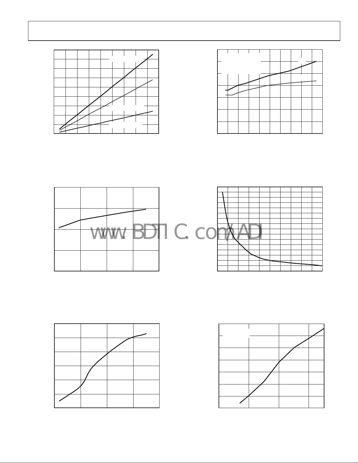
Figure 11. PIN Supply Current vs. Switching Frequency
06090-010
35
TA = 25°C
V
= V
= 5V
IN
30
25
20
15
10
GATE RISE AND FALL TI MES (ns)
5
0
PIN
t
OR
t
IS FROM
R
F
10% TO 90% O F
THE GATE VOLTAGE
05
5 1015202530354045
GATE CAPACITANCE (nF)
Figure 14. GATE Rise and
Fall Times vs. C
t
R
t
GATE
F
0
06090-013
2.60
SDSN = 5V
2.55
(V)
2.50
UVLO
V
2.45
2.40
–50 150
1.03
)
VIN = 5V
1.02
OSC,25°C
f
/
OSC
1.01
f
1.00
0.99
0.98
NORMALIZE D FREQUENCY (
0.97
–50 150
0 50 100
TEMPERATURE (° C)
Figure 12. V
Threshold vs. Temperature
UVLO
0 50 100
TEMPERATURE (° C)
Figure 13. Frequency vs. Temperature
1600
1500
1400
1300
1200
1100
1000
900
(kHz)
800
700
OSC
f
600
500
400
300
200
100
0
0 200
20 40 60 80 100 120 140 160 180
R
06090-011
Figure 15. Oscillator Freq
198
TA = 25°C
R
= 100kΩ
FREQ
197
196
195
(kHz)
OSC
194
f
193
192
191
2
06090-012
345
Figure 16. Oscillator Freq
(kΩ)
FREQ
uency vs. Resistance
V
(V)
IN
uency vs. V
06090-014
06090-015
IN
Rev. A | Page 9 of 32
ADP1621
www.BDTIC.com/ADI
250
VIN = 5V
CS = 30V
200
1.6
1.4
1.2
VIN = 5V
SDSN = 0V
150
100
TEMPERATURE ( °C)
50
0
–40 160
10 60 110
CS LEAKAGE (n A)
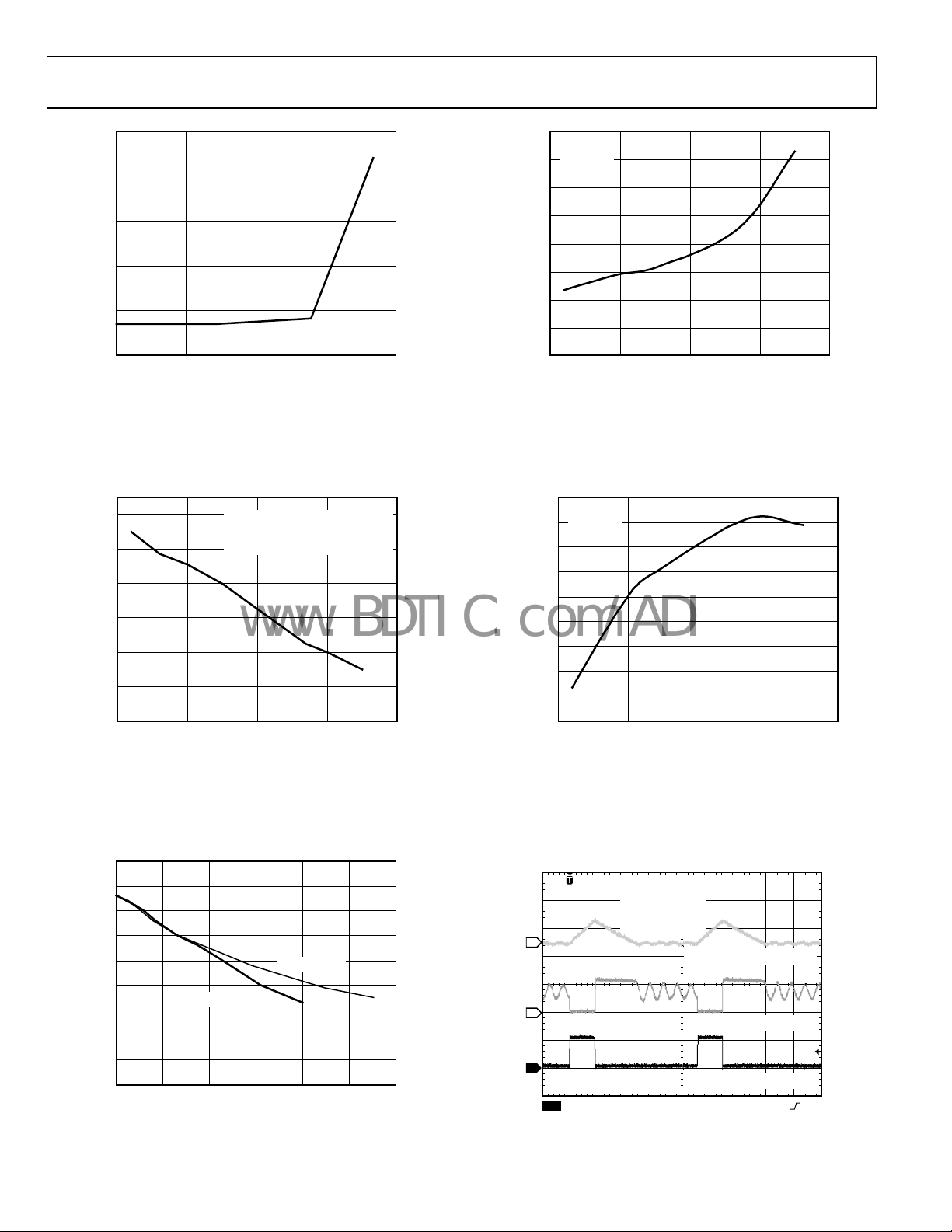
Figure 17. Temperature vs. CS Leakage
8
4
0
–4
–8
FB BIAS CURRENT (n A)
–12
–16
–50 150
VFB = 1.2113V AT 25° C
FB BIAS CURRENT I S MEASURED
BY FORCING A CONSTANT 1. 2113V
OVER THE T EMPERATURE RANGE .
0 50 100
TEMPERATURE (° C)
Figure 18. FB Bias Current vs. Temperature
1.0
0.8
0.6
0.4
SHUTDOWN IN CURRENT (µA)
0.2
0
–50 150
06090-016
0 50 100
TEMPERATURE (° C)
06090-019
Figure 20. Shutdown IN Current vs. Temperature
1.2165
VIN = 5V
1.2160
SDSN = 0V
1.2155
1.2150
1.2145
(V)
FB
V
1.2140
1.2135
1.2130
1.2125
1.2120
–50 150
06090-017
050100
TEMPERATURE ( °C)
Figure 21. FB Volta
ge vs. Temperature
06090-020
90
80
70
60
50
40
30
20
10
PEAK SLOPE CO MPENSATIO N CURRENT (µA)
0
1.0
1.2 1.4 1.6 1.8 2. 0
f
OSC
= 550kHz
Figure 19. Slope-Compensation Current vs. f
f
SYNC/fOSC
f
OSC
= 200kHz
SYNC/fOSC
2.2
06090-018
Rev. A | Page 10 of 32
4
2
1
CH1 5V CH2 5V
Figure 22. DCM Switching Waveform
TA = 25°C
V
= 3.3V
IN
V
= 5V
OUT
LOAD = 0.1A
DCM OPERATIO N
CH4 500mAΩ
CH4 = INDUCTOR CURRENT
CH2 = DRAIN VOLT AGE
CH1 = GATE
M2µs A CH1 2.9V
06090-021

ADP1621
www.BDTIC.com/ADI
TA = 25°C
V
IN
V
OUT
4
= 3.3V
= 5V
LOAD = 0.3A
CCM OPERATIO N
CH4 = INDUCTOR CURRENT
LOAD CURRENT
FROM 0.2A TO 1.2A
4
2
1
CH1 5V CH2 5V
TA = 25°C
= 3.3V
V
IN
= 5V
V
OUT
f
= 220kHz
SW
SOFT-START = 9.3ms
2
1
3
CH1 1V
CH3 5V
1
CH1 50mV
CH4 1AΩ
M200µs A CH4 700V
CH4 500mAΩ
CH2 = DRAIN VOLT AGE
CH1 = GATE
M2µs A CH1 2.9V
06090-022
Figure 23. CCM Switching Waveform Figure 26. Load Transient Response o
TA = 25°C
= 5V
V
CH1 = V
OUT
CH2 = SDSN
CH3 = GATE
CH2 5V M2ms A CH1 4.5V
Figure 24. Soft Start Waveform
06090-023
Figure 27. Line Transient Response of
OUT
NO LOAD AT V
1
2
CH1 50mV CH2 2V M400µs A CH2 3.8V
OUT
the Configuration Shown in Figure 1
wit
h No Load
OUTPUT, AC-COUPLED
TA = 25°C
= 3.3V
V
IN
= 5V
V
OUT
f the Circuit Shown in Figure 1
CH1 = V
CH2 = VIN FROM 3V TO 4V
, AC-COUPLED
OUT
06090-025
6090-026
TA = 25°C
= 5V
V
OUT
LOAD AT V
1
2
CH1 50mV CH2 2V M400µs A CH2 3.8V
Figure 25. Line Transient Response of
OUT
= 1A
CH1 = V
CH2 = VIN FROM 3V TO 4V
, AC-COUPLED
OUT
the Configuration Shown in Figure 1
wit
h a 1 A Load
6090-024
Rev. A | Page 11 of 32

ADP1621
V
www.BDTIC.com/ADI
THEORY OF OPERATION
The ADP1621 is a fixed-frequency, current-mode, step-up dc/dc
converter controller. It drives an external n-channel MOSFET
to step the input voltage up to a higher output voltage. It can be
used for SEPIC, flyback, boost, buck-boost, forward, and other
converter topologies. It operates at a fixed switching frequency that
is set by an external resistor over a range of 100 kHz to 1.5 MHz,
and it can be synchronized to an external clock by connecting
the SDSN pin to the clock.
The input supply current to the ADP1621 is less than 3 mA
d
uring normal operation and less than 10 μA during shutdown.
The ADP1621 can drive large external MOSFETs, allowing it to
support load currents in excess of 10 A.
CONTROL LOOP
The ADP1621 uses a current-mode architecture to regulate the
output voltage. The output voltage is monitored at FB through
a resistive voltage divider. The voltage at FB is compared to the
internal 1.215 V reference voltage by the internal transconductance
error amplifier to create an error current at COMP. A resistorcapacitor compensation impedance connected from COMP to
GND converts the error current to an error voltage.
At the beginning of the switching cycle, the MOSFET is turned
n and the inductor current ramps up. The MOSFET current is
o
measured and converted to a voltage using R
added to the stabilizing slope-compensation ramp. The resulting
voltage sum passes through the current-sense amplifier to generate
the current-sense voltage. When the current-sense voltage is
greater than the COMP error voltage, the MOSFET is turned off
and the inductor current ramps down until the internal clock
initiates the next switching cycle. The duty-cycle of the PWM
modulator is thus adjusted to provide the necessary load current
at the desired output voltage. Because the output voltage ultimately
controls the peak inductor current through the COMP error
voltage, this scheme is referred to as peak current-mode control.
With light loads, the converter can also operate under discon-
nuous conduction mode and pulse-skipping modulation to
ti
maintain output-voltage regulation. These two forms of operation
are discussed in detail in the
ote that the converter can also be designed to operate in
N
Light Load Operation section.
discontinuous conduction mode at full load if desired.
Overall, the current-mode regulation system of the ADP1621
lows fast transient responses while maintaining a stable output
al
voltage. By selecting the proper resistor-capacitor network from
COMP to GND, the regulator response can be optimized for a
wide range of input voltages, output voltages, and load currents.
CS
or R
DSON
and is
CURRENT-SENSE CONFIGURATIONS
The ADP1621 can sense the current across the on resistance of
the MOSFET to minimize external component count and improve
efficiency by eliminating the power that would be lost in a currentsense resistor. This lossless technique eliminates the need for an
expensive current-sense resistor. In the lossless mode configuration,
the voltage at the CS pin (or the switch-node voltage at the drain of
the MOSFET) must not exceed 30 V (see
zes efficiency and reduces cost. In practice, when the
maximi
calculated V
measure the actual V
approaches 30 V, one should build the board and
SW
before committing to the lossless mode
SW
design. Because of the parasitic inductance in the diode, output
capacitor, and PCB traces, V
typically has narrow peaks that
SW
exceed the theoretical maximum voltage at V
V
and the forward-voltage drop of Diode D1. If the measured
OUT
peak voltage exceeds 30 V, or if a more accurate current limit is
desired, then the CS pin can be connected to an external currentsense resistor in the source of the MOSFET (
imum power output is limited by the selection of the
max
external components.
V
IN
PIN
IN
ADP1621
SDSN
PGND
Figure 28. CS Pin Connection for V
Figure 29. CS Pin Connection for V
(No Current-Sense Resistor Needed)
V
IN
PIN
ADP1621
SDSN
PGND
with a Current-Sense Resistor, R
CS
GATE
GND
IN
GATE
CS
GND
Figure 28). This technique
—the sum of
SW
Figure 29). The
D1
L
R
S
< 30 V, Lossless Mode
SW
L
R
S
> 30 V, Resistor Sense Mode
SW
V
OUT
V
SW
C
O
06090-027
D1
SW
V
OUT
C
O
R
CS
06090-028
CS
Rev. A | Page 12 of 32

ADP1621
www.BDTIC.com/ADI
CURRENT LIMIT SETTING THE OSCILLATOR FREQUENCY AND
The current limit is achieved by the COMP voltage clamp, owing
to the current-mode operation of the ADP1621. A detailed
explanation of how the current limit is determined can be found
in the
Current Limit section of the Application Information:
ost Converter section.
Bo
UNDERVOLTAGE LOCKOUT
An internal undervoltage lockout (UVLO) circuit at the IN pin
holds the GATE voltage low when the IN voltage is below the
UVLO voltage, which is typically 2.5 V.
SHUTDOWN
The ADP1621 goes into shutdown approximately 50 μs after the
SDSN pin is pulled low or left floating. There is an internal 100 kΩ
resistor connected between SDSN and GND.
When the junction temperature of the ADP1621 reaches about
150°C, t
he ADP1621 goes into thermal shutdown and the GATE
voltage is pulled low. When the junction temperature drops below
about 140°C, the ADP1621 resumes normal operation after the
soft start sequence.
SOFT START
The ADP1621 has an internal soft start circuit that ramps
the FB regulation voltage from 0 V to 1.215 V in 64 steps over
2048 clock oscillator cycles. This soft start ramp allows the
output voltage to slowly rise to the steady-state output voltage,
preventing input inrush current at startup.
INTERNAL SHUNT REGULATORS
The IN and PIN pins each have an internal shunt regulator that
allows the ADP1621 to operate over a wide input voltage range.
The shunt regulators limit the voltages at IN and PIN to about
5.5 V, allowing the use of logic-level MOSFETs independent of
the input and/or output voltage. The shunt regulator voltage can
reach 5.7 V at 10 mA. See
t
hese shunt regulators.
The internal power is derived from the IN pin, whereas the
MOS
FET gate driver (GATE) current comes from the power
input, PIN. By separating the two inputs, PIN can be driven
with an external small-signal NPN transistor to limit the power
loss in the PIN shunt regulator when the input voltage is higher
than 5.5 V. See
oing into PIN and IN should not exceed 35 mA and 25 mA,
g
Figure 37 for an example. The maximum currents
respectively.
Figure 9 for the I-V characteristics of
SYNCHRONIZATION FREQUENCY
The free-running oscillator frequency, f
from FREQ to GND. A 100 kΩ resistor sets the typical oscillator
frequency to 200 kHz, a 65 kΩ resistor sets it to 325 kHz, a 32 kΩ
resistor sets it to 600 kHz, and a 10 kΩ resistor sets it to 1.5 MHz.
Figure 30 shows a typical relationship between f
1600
1500
1400
1300
1200
1100
1000
900
(kHz)
800
700
OSC
f
600
500
400
300
200
100
0
20 40 60 80 100 120 140 160 180
0 200
(kΩ)
R
FREQ
Figure 30. f
OSC
vs. R
The switching frequency can be synchronized to an external clock
b
y driving the SDSN pin with that clock signal. The SDSN pin
serves the two functions of shutdown control and frequency
synchronization input. If the SDSN input detects a low-to-high
transition within 10 μs of a high-to-low transition, it resets the
oscillator to synchronize to the frequency of the signal at SDSN.
The ADP1621 only synchronizes to frequencies greater than the
free-running switching frequency. To ensure proper synchronization
operation, set the synchronization frequency, f
running frequency, f
f
. Although the switching frequency can be synchronized to as
SYNC
. The switching frequency, fSW, is equal to
OSC
high as 1.8 MHz, the peak slope-compensation current decreases at
higher f
1.4× of f
. It is recommended that the maximum f
SYNC
. The slope-compensation resistor, RS, should be chosen
OSC
for the synchronization frequency (see the Slope Compensation
s
ection). For SDSN to detect a high input, the high state must
remain high for at least 100 ns.
, is set by a resistor
OSC
and R
OSC
FREQ
, to 1.2× the free-
SYNC
SYNC
.
FREQ
06090-029
be less than
Rev. A | Page 13 of 32

ADP1621
VVV
×
I
I
Δ
(
)
−××
www.BDTIC.com/ADI
APPLICATION INFORMATION: BOOST CONVERTER
In this section, an analysis of a boost converter is presented,
along with guidelines for component selection. A typical boostconverter application circuit is shown in
Figure 1.
DUTY CYCLE
To determine the worst-case inductor current ripple, output voltage
ripple, and slope-compensation factor, it is first necessary to
determine the system duty cycle. The duty cycle in continuous
conduction mode (CCM) is calculated by the equation
−+
OUT
D
=
where V
is the desired output voltage, VIN is the input
OUT
voltage, and V
OUT
is the forward-voltage drop of the diode. A
D
IND
(1)
VV
+
D
typical Schottky diode has a forward-voltage drop of 0.5 V.
The GATE minimum on and off times determine the minimum
a
nd maximum duty cycles, respectively. The minimum on and
off times are typically 180 ns and 190 ns, respectively. The
minimum and maximum duty cycles are given by
D ×==
D ×−=−=
where D
cycle, t
time, t
MIN
MAX
MIN
ON,MIN
is the switching period, and fSW is the switching frequency.
SW
,
t
SW
t
,
MINOFF
t
SW
is the minimum duty cycle, D
is the minimum on time, t
ft
(2)
SWMINON
,
)(11
ft
,
(3)
SWMINOFF
is the maximum duty
MAX
is the minimum off
OFF,MIN
t
MINON
Note that when the converter tries to operate at a duty cycle
lo
wer than D
, pulse-skipping modulation occurs to maintain
MIN
the output voltage regulation (see the Light Load Operation
secti
on).
SETTING THE OUTPUT VOLTAGE
The output voltage is set through a voltage divider from the
output voltage to the FB input. The feedback resistor ratio sets
the output voltage of the system. The regulation voltage at FB is
1.215 V. The output voltage is given by (see
R1
V
OUT
⎛
⎜
⎝
⎞
+×=
1V215.1 (4)
⎟
R2
⎠
Figure 1)
The input bias current into FB is 25 nA typical, 70 nA
imum. For a 0.1% degradation in regulation voltage and
max
with 70 nA bias current, R2 must be less than 18 kΩ, which
results in 68 μA of divider current. Choose the value of R1 to set
the output voltage. Using higher values for R2 results in reduced
output voltage accuracy due to the input bias current at the FB
pin, whereas lower values cause increased quiescent current
consumption.
INDUCTOR CURRENT RIPPLE
Choose a peak-to-peak inductor ripple current between 20%
and 40% of the average inductor current. A good starting point
Rev. A | Page 14 of 32
for a design is to choose the peak-to-peak ripple current to be
30% of 1/(1 − D) times the maximum load current:
where ΔI
is the maximum load current required by the application.
INDUCTOR SELECTION
The inductor value choice is important because it dictates
the inductor current ripple and therefore the voltage ripple
at the output.
The average inductor current, I
and the peak-to-peak inductor ripple current is inversely
prop
where f
Assuming continuous conduction mode (CCM) operation, the
peak
Smaller inductor values are typically smaller in size and usually
les
also increases the power loss in the inductor core. Too large an
inductor value results in added expense and may impede load
transient responses because it reduces the effect of slope
compensation.
Assuming the ripple current is 30% of 1/(1 − D) times the maxi
mum load current, a reasonable choice for the inductor value is
From this starting point, modify the inductance to obtain the
r
ight balance of size, cost, and output voltage ripple while
maintaining the inductor ripple current between 20% and 40%
of 1/(1 − D) times the maximum load current. Keep in mind
that the inductor saturation current must be greater than the
peak inductor current. Magnetically shielded inductors are
generally recommended, although they cost slightly more than
unshielded inductors.
Also, losses due to the inductor winding resistance reduce the
ef
where P
inductor, and R
I
MAXLOAD
I
3.0
L
is the peak-to-peak inductor ripple current, and I
L
I
I
AVEL
,
,
×=Δ
LOAD
−=1
1
D
(5)
D
−
LOAD,MAX
, is given by
L,AVE
(6)
ortional to the inductor value:
DV
IN
=Δ
I
L
is the switching frequency, and L is the inductor value.
SW
(7)
Lf
×
SW
inductor current is given by
DV
I
LOAD
=
PKL
,
−
I
L
=
+
D
D
−
×
INLOAD
+
2121
(8)
Lf
××
SW
s expensive, but increase the ripple current. Larger ripple current
DDV
IN
L
=
3.0
1
If
××
(9)
MAXLOADSW
,
ficiency of the boost converter. This power loss is given by
2
I
⎞
⎛
P ×
LOAD
=
⎜
WL
,
L,W
D
−
1
⎝
is the power dissipation in the winding of the
is the winding resistance.
W
(10)
R
⎟
W
⎠

ADP1621
Δ
=
×
=
www.BDTIC.com/ADI
INPUT CAPACITOR SELECTION
The bulk input capacitor provides a low impedance path for the
inductor ripple current. Capacitor C1 in Figure 1 represents a
b
ulk input capacitor. Choose a bulk input capacitor whose
impedance at the switching frequency is lower than the
impedance of the voltage source V
.
IN
The preferred bulk input capacitor is a 10 μF to 100 μF ceramic
pacitor because it has low equivalent series resistance (ESR) and
ca
low impedance. Aluminum electrolytic and aluminum polymer
capacitors can also be used as the bulk input capacitors. The bulk
input capacitor does not need to be placed very close to the IN
and PIN pins. Aluminum electrolytic capacitors are the cheapest
and generally have high ESR values, which increase dramatically at
temperatures less than 0°C. Some aluminum electrolytic capacitors
have ESR less than 20 mΩ, but their capacitances are generally
greater than 800 μF. Aluminum polymer capacitors are more
expensive than the aluminum electrolytic ones, but are generally
cheaper than the ceramic capacitors for the same amount of
capacitance. Polymer capacitors have relatively low ESR, with
some models having less than 10 mΩ.
Regardless of the type of capacitor used, make sure the ripple
c
urrent rating of the bulk input capacitor, I
IIΔ
1
×=
(11)
2
where ΔI
,LRMSCIN
L
3
is the peak-to-peak inductor ripple current.
, is greater than
CIN,RMS
In addition to the bulk input capacitor, a bypass input capacitor is
equired. The function of the bypass capacitor is to locally filter the
r
input voltage to the ADP1621 and maintain the input voltage at a
steady value during switching transitions. The bypass capacitor is
typically a 0.1 μF or greater ceramic capacitor and should be placed
as close as possible to the IN and PIN pins of the ADP1621.
Capacitors C3 and C4 in
Figure 1 represent the bypass capacitors.
OUTPUT CAPACITOR SELECTION
The output capacitor maintains the output voltage and supplies
current to the load while the external MOSFET is on.
The value and characteristics of the output capacitor greatly
ffect the output voltage ripple and stability of the converter.
a
The amount of peak-to-peak output voltage ripple, ΔV
be approximated by
V
where ΔI
⎜
OUT
is the peak-to-peak inductor ripple current, fSW is the
L
−
⎝
⎛
⎜
⎜
2
SW
⎝
I
⎛
LOAD
≈Δ
switching frequency, C
effective ESR of C
inductance of C
OUT
OUT
I
⎞
L
+
D
1
Cf
××π
OUT
×
⎟
21
⎠
2
⎞
OUT
⎟
⎟
⎠
()
2
SW
is the output capacitance, ESR is the
, and ESL is the effective equivalent series
.
Because the output capacitor is typically greater than 40 μF, the
ES
R dominates the output capacitance impedance and thus the
output voltage ripple. The use of low ESR, ceramic dielectric
capacitors is preferred, although aluminum electrolytic,
tantalum, OS-CON™ (from Sanyo), and aluminum polymer
capacitors can be used. At higher switching frequencies, the ESL
of the output capacitor may also be a factor in determining the
output voltage ripple. Multiple capacitors can be connected in
parallel to reduce the effective ESR and ESL. Keep in mind that
the capacitance of a given capacitor typically degrades with
increased temperature and bias voltage. Consult the capacitor
manufacturer’s data sheet when determining the actual
capacitance of a capacitor under certain conditions.
Ensure that the output capacitor ripple current rating, I
is greater than
D
×=
II
LOAD
RMSCOUT
,
(13)
D
−
1
DIODE SELECTION
The diode conducts the inductor current to the output capacitor
and load while the MOSFET is off. The average diode current is
the load current:
II
(14)
LOADAVEDIODE
,
The rms diode current in continuous conduction mode is given by
I
I
where D is t
LOAD
= 1
,
RMSDIODE
D
−
1
he duty cycle.
The power dissipated in the diode is
IVP
D
LOAD
where V
DIODE
is the forward-voltage drop of the diode.
D
(15)
D
−×
(16)
, can
OUT
22
(12)
ESLfESR
××π++
COUT,RMS
,
Rev. A | Page 15 of 32

ADP1621
(
I
+
=
+
=
www.BDTIC.com/ADI
The total power dissipation determines the diode junction
temperature, which is given by
θPTT ×+=
(17)
,
where T
perature, and θ
is the junction temperature, TA is the ambient tem-
J,DIODE
is the junction-to-ambient thermal resistance
JA
of the diode package. The diode junction temperature must not
exceed its maximum rating at the given power dissipation level.
For high efficiency, Schottky diodes are recommended. The low
rward-voltage drop of a Schottky diode reduces the power losses
fo
during the MOSFET off time, and the fast switching speed reduces
the switching losses during the MOSFET transitions. However,
for high voltage, high temperature applications where the reverse
leakage current of the Schottky diode can become significant
and degrade efficiency, use an ultrafast-recovery junction diode.
Make sure that the diode is rated to handle the average output
lo
ad current. Many diode manufacturers derate the current
capability of the diode as a function of the duty cycle. Verify
that the diode is rated to handle the average output load current
with the minimum duty cycle. Also, ensure that the peak inductor
current is less than the maximum rated current of the diode.
MOSFET SELECTION
When turned on, the external n-channel MOSFET allows
energy to be stored in the magnetic field of the inductor. When
the MOSFET is turned off, this energy is delivered to the load to
boost the output voltage.
The choice of the external power MOSFET directly affects the
oost converter performance. Choose the MOSFET based on
b
the following: threshold voltage (V
maximum voltage and current ratings, and gate charge.
The minimum operating voltage of the ADP1621 is 2.9 V.
hoose a MOSFET with a V
C
minimum input supply voltage at PIN used in the application.
Ensure that the maximum V
a few volts greater than the maximum voltage that is applied to
PIN. Ensure that the maximum V
exceeds the maximum V
on parasitics, the MOSFET may be exposed to voltage spikes that
exceed the sum of V
Estimate the rms current in the MOSFET under continuous
co
nduction mode by
I
,
RMSMOSFET
where D is t
he duty cycle. Derate the MOSFET current at least
20% to account for inductor ripple and changes in the forwardvoltage drop of the diode.
and the forward-voltage drop of the diode.
OUT
I
LOAD
=
1
−
JADIODEADIODEJ
), on resistance (R
T
that is at least 0.3 V less than the
T
rating of the MOSFET is at least
GS
rating of the MOSFET
DS
by at least 5 V to 10 V. Depending
OUT
(18)
D
×
D
DSON
),
The MOSFET power dissipation due to conduction is thus
2
I
⎞
⎛
P
where P
LOAD
= 1
C
is the conduction power loss, and R
C
⎟
⎜
D
−
1
⎠
⎝
DSON
(19)
(
KRD
+×××
)
is the MOSFET
DSON
on resistance. The variable K is a factor that models the increase
with temperature:
of R
DSON
oo
(20)
)
C25C/005.0
−×=
where T
TK
J,MOSFET
is the MOSFET junction temperature. Note that
J,MOSFE T
multiple n-channel MOSFETs can be placed in parallel to reduce
the effective R
DSON
.
The power dissipation due to switching transition loss is
a
pproximated by
LOAD
VV
×+
D
()
D
−
1
2
ftt
×+×
FR
SW
(21)
P
SW
where P
SW
time, and t
()
OUT
=
is the switching power loss, tR is the MOSFET rise
is the MOSFET fall time. The MOSFET rise and fall
F
times are functions of both the gate drive circuitry and the
MOSFET used in the application.
The total power dissipation of the MOSFET is the sum of the
nduction and transition losses:
co
PPP
(22)
SWC
where P
MOSFET
is the total MOSFET power dissipation. Ensure
MOSFET
that the maximum power dissipation is significantly less than
the maximum power rating of the MOSFET.
The total power dissipation also determines the MOSFET
unction temperature, which is given by
j
θPTT ×
(23)
MOSFETJ
,
where T
is the junction temperature, TA is the ambient
J,MOSFE T
temperature, and θ
A
MOSFET
is the junction-to-ambient thermal
JA
JA
resistance of the MOSFET package. The MOSFET junction
temperature must not exceed its maximum rating at the given
power dissipation level.
If lossless current sensing is not used, there will also be power
ssipation in the external current-sense resistor, R
di
dissipation, P
, in the external resistor due to conduction losses
CS
. The power
CS
is given by
2
I
⎛
⎞
LOAD
=
P ××
⎜
CS
⎟
−
D
1
⎝
⎠
(24)
RD
CS
LOOP COMPENSATION
The ADP1621 uses external components to compensate the
regulator loop, allowing optimization of the loop dynamics for
a given application.
The step-up converter produces an undesirable right-half plane
RHP) zero in the regulation feedback loop. This RHP zero
(
requires compensating the regulator such that the crossover
Rev. A | Page 16 of 32

ADP1621
V
V
×
×
www.BDTIC.com/ADI
frequency occurs well below the frequency of the RHP zero. The
location of the RHP zero is determined by the following equation:
R
2
LOAD
(25)
L
×π
2
is the equivalent
LOAD
where f
()
1
Df
RHPZ
,
is the RHP zero frequency, and R
Z,RHP
×−=
load resistance or the output voltage divided by the load current.
To stabilize the regulator, ensure that the regulator crossover
requency is less than or equal to one-fifth of the RHP zero
f
frequency and less than or equal to one-fifteenth of the switching
frequency. For an initial practical design, choose the crossover
frequency f
to be the lower of
C
f
SW
f =
C
15
(26)
Once the compensation resistor, R
formed by the resistor and compensation capacitor, C
one-fourth of the crossover frequency, or
COMP
=
2
(31)
RfC××π
COMPC
Capacitor C2 is chosen to cancel the zero introduced by the output
ca
pacitance ESR. Thus, C2 should be set to (see
CESR
OUT
=2
C
where ESR r
R
COMP
epresents the ESR of C
(32)
For low ESR output capacitors, such as ceramic capacitors, C2
is s
mall, generally in the range of 10 pF to 400 pF. Because of the
parasitic inductance, resistance, and capacitance of the PCB layout,
and
f
,RHPZ
f = (27)
C
5
where f
is the crossover frequency, and fSW is the switching
C
frequency.
the R
observing the load transient response of the ADP1621 to establish a
stable operating system and achieve optimal transient performance.
For most applications, R
and C
The regulator loop gain is
FB
A ×
VL
where A
()
V
OUT
is the loop gain, VFB is the feedback regulation
VL
voltage (typically 1.215 V), V
D is the duty cycle, g
m
gain (typically 300 μS), Z
ZgD
m
COMP
is the regulated output voltage,
OUT
is the error amplifier transconductance
is the impedance of the RC network
COMP
from COMP to GND, n is the current-sense amplifier gain
(typically 9.5), R
is the current-sense resistance, and Z
CS
the impedance of the load and output capacitor. In the case of
lossless current sensing, as shown in Figure 28, R
on resistance, R
represents the external current-sense resistor, as shown in
R
CS
, of the external power MOSFET. Otherwise,
DSON
Figure 29.
To determine the crossover frequency, it is important to note
th
at at that frequency the compensation impedance, Z
dominated by Resistor R
, and the output impedance, Z
COMP
is dominated by the impedance of the output capacitor, C
When solving for the crossover frequency, the equation is
simplified to
=||VLA
FB
V
OUT
()
1
RgD
COMP
×××−×
×
m
1
||1
×××−×=
Rn
×
CS
Z
OUT
(28)
||
SLOPE COMPENSATION
The ADP1621 includes a circuit that allows adjustable slope
compensation. Slope compensation is required by current-
is
OUT
is equal to the
CS
, is
COMP
,
OUT
.
OUT
×
11
CfRn
××π
2
CCS
OUT
1
=
mode regulators to stabilize the current-control loop when
operating in continuous conduction and the switching duty
cycle is greater than 50%.
Slope compensation is achieved by internally forcing a ramping
c
urrent source out of the CS current-sense pin. By placing a resistor
between the CS pin and the current sensing device (the drain of
the external MOSFET in the case of lossless current sensing or
the source of the MOSFET if a current-sense resistor is used), a
voltage is developed across the resistor that is proportional to
the slope-compensation current.
To ensure stability of the current-mode control loop, use a
co
half of the current-sense representation of the inductor current
downslope. Therefore, it follows that
(29)
where fC is the crossover frequency, R
resistor, and C
Solving for R
R
COMP
is the output capacitance.
OUT
gives
COMP
2
C
=
OUT
()
1
FB
×−×
is the compensation
COMP
VRnCf
×××××π
CS
OUT
gDV
m
(30)
where R
compensation current, f
current-sense resistor, V
forward-voltage drop of the diode, V
the minimum off time, and L is the power-stage inductor. In the
case of lossless current sensing, R
, C
COMP
COMP
, and C2 values might need to be adjusted by
COMP
is in the range of 5 kΩ to 100 kΩ,
COMP
is in the range of 100 pF to 30 nF.
REF
2
Figure 31. Compensation Components
COMP
g
m
mpensation voltage slope that is equal to or greater than one-
fI
R
××12
S
is the slope-compensation resistor, I
S
SWSC,PK
×−
ft
SWMINOFF,
is the switching frequency, RCS is the
SW
is the regulated output voltage, VD is the
OUT
, is known, set the zero
COMP
COMP
Figure 31)
.
OUT
3
R
COMP
COMP
OUT
C2
06090-030
−+
VVV
IND
L
is the peak slope-
SC,PK
(33)
C
×>
R
CS
is the input voltage, t
IN
is equal to the on resistance,
CS
, to
OFF,MIN
is
Rev. A | Page 17 of 32

ADP1621
(
)
(
)
(
×−=
(
−××
www.BDTIC.com/ADI
R
, of the external power MOSFET. Otherwise, RCS
DSON
represents the external current-sense resistor.
Solving for R
R
Keep in mind that the above inequality is a function of both
AD
P1621 parameters and off-chip components, the values of
which vary from part to part and with temperature. Select R
ensure current-loop stability for all possible variations.
After accounting for parameter variations, use values of R
are as close to the calculated limit as possible because excessive
slope compensation reduces the benefits of current-mode control
and increases the “softness” of the current limit, as discussed in the
Current Limit section. Given a typical peak slope-compensation
urrent of 70 μA, R
c
at the CS pin is typically clamped at 116 mV. It is also recommended that R
than 1.6 kΩ, the parameters in Equation 34, such as R
can be adjusted such that R
In conclusion, the value of R
CURRENT LIMIT
The current limit in the ADP1621 limits the peak inductor
current and is achieved by the COMP voltage clamp. The peak
inductor current, I
I
PKL
,
where V
V
COMP,ZCT
n is the current-sense amplifier gain (typically 9.5), I
peak slope-compensation current (typically 70 μA), R
slope-compensation resistor, D is the duty cycle, f
switching frequency, t
190 ns), and R
lossless current sensing, R
of the external power MOSFET. Otherwise, R
external current-sense resistor.
The current limit in the ADP1621 is a “soft” current limit.
hen the inductor current reaches the I
W
Equation 35, the duty cycle decreases, and the output voltage
drops below the desired voltage. The I
then increases in response to the smaller duty cycle, D. The
larger the slope-compensation resistor, R
on I
L,PK
in a “soft” current limit for the ADP1621. Use values of R
as close as possible to the calculated limit derived from
Equation 34. If high-precision current limiting is required,
consider inserting a fuse in series with the inductor.
Also, keep in mind that the current limit is a function of both
AD
P1621 parameters and off-chip components, the values of
gives the slope-compensation criterion:
S
ftVVVR
CS
>
S
=
COMP,CLAMP
1
OUT
be greater than 20 Ω. If the calculated RS is greater
S
IND
2
should not exceed 1.6 kΩ because the voltage
S
L,PK
SWPKSC
,
is less than 1.6 kΩ.
S
should be 20 Ω ≤ RS ≤ 1.6 kΩ.
S
, is given by
VV
−
n
R
CS
is the COMP clamp voltage (typically 2.0 V),
×−×−+×
SWMINOFF
,
LfI
×××
−
1
(34)
that
S
, fSW, and L,
CS
DRI
××
SPKSCZCTCOMPCLAMPCOMP
,,,
ft
×−
SWMINOFF
,
(35)
is the COMP zero-current threshold (typically 1.0 V),
is the
SC,PK
is the
S
is the
SW
is the minimum off time (typically
OFF,MIN
is the current-sense resistor. In the case of
CS
is equal to the on resistance, R
CS
represents the
CS
limit given in
L,PK
limit in Equation 35
L,PK
, the larger the effect
S
DSON
for an incremental decrease in D. This behavior results
that are
S
to
S
,
Rev. A | Page 18 of 32
which vary from part to part and with temperature. If lossless
current sensing is used, consider that the on resistance of a
MOSFET typically increases with increasing junction temperature.
The peak inductor current limit also limits the maximum load
current at a given output voltage. The maximum load current,
assuming CCM operation, is given by
)
DI
MAXLOAD1,
⎛
⎜
⎜
−
n
⎜
⎜
⎜
⎝
××
VV
R
CS
,,,
−
1
DRI
SPKSCZCTCOMPCLAMPCOMP
×−
ft
SWMINOFF
,
−
2
⎞
⎟
×
DV
⎟
IN
⎟
××
Lf
SW
⎟
⎟
⎠
(36)
If the load current exceeds I
, the output voltage drops
LOAD,MAX
below the desired voltage.
LIGHT LOAD OPERATION
Discontinuous Conduction Mode
With light loads, the average inductor current is small, and,
depending on the converter design, the instantaneous inductor
current may reach 0 during the time when the MOSFET is off.
This mode of operation is termed discontinuous conduction
mode. The condition for entering discontinuous conduction
mode in a boost converter is
1
)
LOAD
2
IN
<
I
When the instantaneous inductor current reaches 0 during the
c
ycle, the inductor ceases to be a current source, and ringing
can be observed in the waveforms of the MOSFET drain voltage
and the inductor current. The frequency of the ringing is the
resonant frequency of the inductor and the total capacitance
from the SW node to GND, which includes the capacitances of
the MOSFET and diode, and any parasitic capacitances from
the PCB. While adding a resistive element, such as a snubber, to
the system further dampens the resonance, it also decreases the
efficiency of the regulator.
Pulse-Skipping Modulation
The ADP1621 features circuitry that improves the converter
efficiency and minimizes power consumption with no load or
very light loads. When the COMP voltage drops below V
(typically 1.0 V), which can occur at sufficiently light loads, the
MOSFET is powered off until the FB voltage drops below 1.215 V.
Then, the error amplifier drives the COMP voltage higher, and
the converter resumes switching when the COMP voltage rises
above the V
COMP,ZCT
the output capacitor supplies current to the load.
With light loads, the COMP voltage hovers around 1.0 V, and
s
hort periods of switching are followed by long periods of the
MOSFET being powered off. This pulse-skipping modulation
operation improves converter efficiency by reducing the number of
switching cycles and therefore reducing the gate drive current and
the switching transition power loss.
DDV
(37)
fL
××
SW
COMP,ZCT
voltage. While the MOSFET is powered off,

ADP1621
www.BDTIC.com/ADI
Given the minimum on time of the ADP1621, pulse-skipping
modulation is also a requirement to maintain output voltage
regulation with light loads. During the short switching periods
of pulse-skipping modulation, the MOSFET is turned on for the
RECOMMENDED COMPONENT MANUFACTURERS
Table 5.
Vendor Components
AVX Corporation Capacitors
Central Semiconductor Corp. Diodes
Coilcraft, Inc. Inductors
Diodes, Inc. Diodes
International Rectifier Diodes, MOSFETs
Murata Manufacturing Co., Ltd. Capacitors, inductors
ON Semiconductor Diodes, MOSFETs
Rubycon Corporation Capacitors
Sanyo Capacitors
Sumida Inductors
Taiyo Yuden, Inc. Capacitors, inductors
Toko America, Inc. Inductors
United Chemi-Con, Inc. Capacitors
Vishay Siliconix Diodes, MOSFETs, resistors, capacitors
minimum on time each cycle, storing just enough energy in the
inductor to charge the output capacitor. During the long period
when the MOSFET is off, no current flows through the inductor,
and the light load current is supplied by the output capacitor.
Rev. A | Page 19 of 32

ADP1621
www.BDTIC.com/ADI
LAYOUT CONSIDERATIONS
Layout is important for all switching regulators, but is particularly important for regulators with high switching frequencies.
To achieve high efficiency, good regulation, and stability, a welldesigned printed circuit board layout is required. A sample PCB
layout for the standard boost converter circuit shown in Figure 33
Figure 32.
iven in
is g
Follow these guidelines when designing printed circuit boards:
• Keep the low ESR bypass input capacitor of 0.1 μF or higher
close to IN/PIN and GND.
• Keep the high current path from Bulk Input Capacitor C1
through Inductor L1 and MOSFET M1 to PGND as short
as possible.
• Keep the high current path from Bulk Input Capacitor C1
through Inductor L1, Diode D1, and Output Capacitor C
to PGND as short as possible. Place C
as close to PGND
OUT
as possible to reduce ground bouncing.
• Keep high current traces as short and wide as possible to
minimize parasitic series inductance, which causes spiking
and electromagnetic interference (EMI).
• To minimize switching noise, the drain of the power MOSFET
should be placed very close to the inductor, and the source
of the MOSFET (or the bottom side of the sense resistor)
should be connected directly to the power GND plane. Use
wide copper traces on the drain and on the source of the
MOSFET to minimize parasitic inductance and resistance.
Parasitic inductance can lead to excessive ringing during
switching transitions, and parasitic resistance reduces the
converter efficiency. Make sure that the MOSFET selected
is capable of handling the total power loss (conduction plus
transition losses) in the application circuit.
OUT
• Avoid routing high impedance traces near any node con-
nected to the switch node (the MOSFET drain) or near
Inductor L1 to prevent radiated switching-noise injection.
• Add an extra copper plane at the connection of the MOSFET
drain and the anode of the diode to help dissipate the heat
generated by losses in those components.
• Avoid ground loops by having one central ground node on the
PCB. If this is impractical, place the power ground with high
current levels physically closer to the PCB ground terminal.
The analog, low current-level ground should be placed farther
from the PCB ground terminal.
• Minimize the length of the PCB trace between the GATE
pin and the MOSFET gate. The parasitic inductance in this
PCB trace can give rise to excessive voltage ringing at the
MOSFET gate and drain, as well as the regulator output. It
is recommended to add 5 Ω of resistance for every inch of
PCB trace. This helps to reduce the overshoot and ringing at
the drain and the output. However, this added resistance
increases the rise and fall times of the MOSFET; thus, the
switching loss in the MOSFET is increased.
• Place the feedback resistors as close to FB as possible to
prevent high frequency switching-noise injection.
• Place the top of the upper feedback resistor, R1, as close
as possible to the top of C
for optimum output voltage
OUT
sensing.
• If a current-sense resistor is connected between the source
of the MOSFET and PGND, ensure that the capacitance from
CS to PGND is minimized.
• Place the compensation components as close as possible
to COMP.
V
IN
L1
SDSN
VIAS TO G ND PLANE
VIAS TO 2ND L AYER
Figure 32. PCB Layout of the Circuit Shown in Figure 33 (2-layer PCB)
C1
M1
GND
C3
C4
ADP1621
C2R1R2
GATE
R
FREQ
COMP
COMP
R
C
S
R
Rev. A | Page 20 of 32
GND
D1
C
OUT1
C
OUT2
C
OUT3
REMOTE OUTPUT
SENSING
V
OUT
6090-031

ADP1621
P
××=
(
)
×+=
(
)
(
)
×
=
www.BDTIC.com/ADI
EFFICIENCY CONSIDERATIONS
The efficiency, η, of a dc/dc converter is given by
η
where P
OUT
P
IN
is the output power, and PIN is the input power to the
OUT
(38)
%100×=
converter. While switching regulators are ideally lossless converters
of power, the nonideal characteristics of regulator components
degrade the efficiency of the regulator.
The primary sources of power dissipation in the regulator include
• The power dissipation in the external power MOSFET due
to conduction and switching losses.
PPP +=
(39)
MOSFET
=
SWC
I
⎡
⎛
⎞
LOAD
⎜
⎢
⎣
⎡
⎢
⎟
−
D
⎝
⎠
VV
OUT
⎢
⎢
⎢
⎣
DSON
I
LOAD
×+
)(
D
D
1
−
2
⎤
+×××
+
)1(1KRD
⎥
⎦
⎤
×+×
ftt
)(
FR
SW
⎥
⎥
⎥
⎥
⎦
• The power dissipation in the external current-sense
resistor if lossless current sensing is not used.
2
I
⎛
⎞
LOAD
=
P ××
⎜
CS
⎟
−
D
1
⎝
⎠
(40)
RD
CS
• The power dissipation in the external diode.
IVP ×=
DIODE
D
(41)
LOAD
• The power dissipation in the winding resistance of the
power stage inductor.
2
I
⎛
⎞
LOAD
=
P ×
⎜
,
WL
−
1
⎝
R
⎟
D
⎠
(42)
W
• The supply current to the ADP1621 IC, which includes the
quiescent current and the gate driver charging current. The
power dissipation due to gate charging loss is approximated by
fQVP
PIN
G
where P
is the gate charging power loss, V
G
the PIN pin, Q
is the MOSFET total gate charge, and fSW is
G
(43)
SWG
is the voltage at
PIN
the converter switching frequency. Therefore, the total power
dissipation in the IC itself is given by
(44)
IVPP
IN
GIC
where P
PIN
is the total power dissipated in the IC, IQ is the
IC
quiescent current, and V
Q
IVfQV ×+×
IN
SWG
is the voltage at the IN pin.
IN
Q
The secondary sources of power dissipation in the regulator include
• The power dissipation in the ESR of the input and output
capacitors.
• Inductor core losses due to hysteresis and eddy currents.
Rev. A | Page 21 of 32

ADP1621
V
V
www.BDTIC.com/ADI
EXAMPLES OF APPLICATION CIRCUITS
STANDARD BOOST CONVERTER— DESIGN EXAMPLE
The example covered here is for the ADP1621 configured as a
standard boost converter, as shown in Figure 33, where lossless
c
urrent sensing is employed. The design parameters are V
3.3 V, V
= 5 V, and a maximum load current of 1 A.
OUT
To begin this design, a switching frequency of 600 kHz is chosen
y setting R
(b
to 32 kΩ, see Figure 30) so that a small inductor
FREQ
and small output capacitors can be used. The duty cycle is calculated from Equation 1 to be 0.4, given a forward-voltage drop of
0.5 V for the Schottky diode. The feedback resistors are calculated
to be R1 = 35.7 kΩ and R2 = 11.5 kΩ from Equation 4.
Assuming that the inductor ripple is 30% of 1/(1 − D) times
th
e maximum load current, the inductor size is calculated to be
about 4.4 μH, according to Equation 9. The small, magnetically
shielded 4.7 μH Toko FDV0630-4R7M inductor is selected.
Because ceramic capacitors have very low ESR (a few milliohms),
a 47 μF/6.3 V Murata GRM31CR60J476M ceramic capacitor is
chosen for the input capacitor. The output voltage ripple for a
given C
, ESR, and ESL can be found by solving Equation 12.
OUT
By choosing an output voltage ripple equal to 1% of the output
voltage, Equation 12 yields that the minimum C
required is
OUT
100 μF and the maximum ESR required is 25 mΩ. Other combinations of capacitance and ESR are possible by choosing a
much larger C
and a larger ESR. In this case, a small 1 μF
OUT
ceramic capacitor and two 150 μF Sanyo POSCAP™ capacitors
are selected. The low ESR ceramic capacitor helps to suppress
the high frequency overshoot at the output. POSCAP has low
ESR and high capacitance in a relatively small package. Ceramic
capacitors can also be used. Generally, bigger ceramic capacitors
are more expensive.
C3
1µF
10V
C2
120pF
f
OSC
C1 = MURATA GRM31CR60J476M
C
OUT3
L1 = TOKO FDV0630-4R7M
C4
0.1µF
10V
R
COMP
9.09kΩ
C
R
COMP
1.8nF
= 600kHz
= SANYO POSCAP 6TPE150M
FREQ
31.6kΩ
1%
Figure 33. Typical Boost Converter Application Circuit
=
IN
PIN
ADP1621
SDSN
COMP
FREQ
GATE
PGND
GND
AGND
M1 = VISHAY Si7882DP
D1 = VISHAY SSA33L
IN
CS
FB
The next step is to choose a Schottky diode. The average
a
nd rms diode currents are calculated to be 1.0 A and 1.3 A,
respectively, using Equations 14 and 15. A Vishay SSA33L
Schottky diode meets the current and thermal requirements
and is an excellent choice.
The power MOSFET must be chosen based on threshold voltage
(V
), on resistance (R
T
), maximum voltage and current ratings,
DSON
and gate charge. The rms current through the MOSFET is given
by Equation 18 as 1.1 A. The Vishay Si7882DP is a 20 V n-channel
power MOSFET that meets the current and thermal requirements.
It comes in a PowerPAK® package and offers low R
charge. At V
= 2.5 V, the on resistance, R
GS
, is 8 mΩ.
DSON
The loop-compensation components are chosen to be R
9.1 kΩ and C
= 1.7 nF from Equations 30 and 31, respectively.
COMP
A roll-off capacitor of C2 = 120 pF is also added. The slopecompensation resistor is set to be R
= 80 Ω from Equation 34.
S
Lastly, given the chosen components, the peak inductor current
as s
et by the current limit circuitry is given by Equation 35 as
= 12 A. Thus, the maximum load current, assuming CCM
I
L,PK
operation, is given by Equation 36 as I
LOAD,MAX
= 8 A, which is
safely above the 1.0 A load current requirement for this design
example. Note that the current limit is a strong function of R
which can vary part to part and with temperature. In addition,
note that R
sense resistor or with the R
can be implemented with an external current-
CS
of a MOSFET. Variations in RCS
DSON
and the other parameters in Equations 35 and 36 must be taken
into account if precise current limiting is necessary. Due to the
parasitic resistance of PCB traces, R
might need to be adjusted
S
on the actual circuit board to achieve the desired current limit.
Keep in mind that R
with a different R
must be less than 1.6 kΩ. Using a MOSFET
S
or adjusting RCS can also set the current
DSON
limit to the desired level.
= 3.3
IN
L1
4.7µH
V
= 5V
R
80Ω
D1
C1
47µF
6.3V
C
1µF
10V
OUT1
M1
R1
35.7kΩ
1%
R2
11.5kΩ
1%
S
C
OUT2
10µF
10V
OUT
1A
C
OUT3
150µF
6.3V
×2
06090-032
DSON
and gate
=
COMP
CS
,
Rev. A | Page 22 of 32

ADP1621
×
=
www.BDTIC.com/ADI
BOOTSTRAPPED BOOST CONVERTER
The inputs of the ADP1621 can be driven from the step-up
converter output voltage to improve efficiency for low input
voltages. For low input voltages, bootstrapped operation improves
efficiency with heavy loads by increasing the available gate drive
voltage, thus reducing the on resistance of the MOSFET. However,
because the internal circuitry is driven from IN, the ADP1621
quiescent current and gate drive current supplied from the input
increases due to the step-up ratio and the conversion efficiency loss.
The circuit shown in Figure 1 shows a bootstrapped boost conv
erter, where V
starts, make sure that the input voltage minus the forward-voltage
drop of the diode is greater than the UVLO voltage and the gate
threshold voltage of the MOFSET. In this example, the MOSFET
has a gate threshold voltage of 2.5 V. The regulator shown in
Figure 1 is very similar to that shown in Figure 33, which is a
s
tandard boost without bootstrapping. Because the same MOSFET
and inductor are used in both circuits and the input and output
conditions are the same, the compensation components remain
unchanged.
Figure 34 shows a bootstrapped application circuit for output
v
oltages greater than 5.5 V. In this case, the output is 12 V.
Notice that a resistor, R3, of 700 Ω is placed between V
the IN and PIN pins to limit the input currents because the IN
and PIN pins are regulated to 5.5 V. A diode, D2, is placed between
and the IN/PIN pins to supply the necessary quiescent current
V
IN
to start the ADP1621. Once the ADP1621 starts and the output
= 3.3 V and V
IN
= 5 V. To ensure that the circuit
OUT
OUT
and
voltage reaches 12 V, the quiescent current stops flowing
through D2 and is supplied by the output. Keep in mind that the
dynamic supply current to PIN increases as the switching frequency increases because more gate drive is needed for a higher
switching frequency. Therefore, R3 needs to be set appropriately.
The PIN supply current can be approximated by
QfI
PIN
where I
and Q
is the PIN supply current, fSW is the switching frequency,
PIN
is the gate charge of a particular MOSFET.
G
(45)
GSW
An alternative implementation to Figure 34 is shown in Figure 35,
w
here an NPN transistor is used to supply the necessary current
to the input PIN at various loads, but the gate drive voltage is
limited to approximately 4.8 V (one diode drop below the
voltage at IN). Signal Diodes D2 and D3 help to provide the
necessary quiescent current to start the ADP1621. Once the
ADP1621 starts, the current stops flowing through these two
diodes because the voltages at PIN and IN are approximately
4.8 V and 5.5 V, respectively. One advantage of this technique
is that Q1 provides enough current to the gate driver at any
switching frequency with a wide range of MOSFETs that have
different gate charge specifications.
Notice that the output capacitor, C
in Figure 34 and Figure 35,
OUT2
is a large aluminum electrolytic capacitor, both in physical size
and capacitance. Such capacitors are very cheap relative to
ceramic capacitors (such as Sanyo POSCAP) or aluminum
polymer capacitors. The ADP1621 can work with a wide range
of capacitor types.
Rev. A | Page 23 of 32

ADP1621
V
V
V
V
www.BDTIC.com/ADI
D2
R3
700Ω
0.1µF
10V
C4
IN
PIN
200Ω
CS
1µF
10V
C3
ADP1621
SDSN
GATE
COMP
R
COMP
51.5kΩ
C2
220pF
f
OSC
C1 = MURATA GRM31CR60J476M
C
OUT2
L1 = COIL CRAFT MSS1260-103ML
C
R
COMP
330pF
= 600kHz
= RUBYCON 25ZL330M8x16
FREQ
31.6kΩ
1%
Figure 34. Bootstrapped Appli
D3
0.1µF
10V
C4
1µF
10V
C3
PGND
FREQ
GND
AGND
M1 = IRF7470
D1 = VISHAY SSC53L
D2 = SIGNAL DIODE
D2
PIN
FB
cation Circuit for V
Q1
R3
1.5kΩ
IN
200Ω
CS
ADP1621
SDSN
GATE
COMP
R
COMP
51.5kΩ
C2
220pF
f
= 600kHz
OSC
C1 = MURATA GRM31CR60J476M
= RUBYCON 25ZL330M8x16
C
OUT2
L1 = COIL CRAFT MSS1260-103ML
Q1 = SIGNAL NPN TRANSI STOR
C
COMP
330pF
R
FREQ
31.6kΩ
1%
Figure 35. Bootstrapped Appli
PGND
FREQ
AGND
FB
GND
M1 = IRF7470
D1 = VISHAY SSC53L
D2, D3 = SIG NAL DIODE
cation Circuit for V
= 3.3
IN
L1
10µH
V
= 12V
C1
47µF
6.3V
C1
47µF
6.3V
C
OUT1
10µF
16V
×2
C
OUT1
10µF
16V
×2
OUT
1A
C
OUT2
330µF
25V
×2
06090-033
V
= 12V
OUT
1A
C
OUT2
330µF
25V
×2
06090-034
D1
M1
IN
L1
10µH
M1
88.7kΩ
= 3.3
D1
88.7kΩ
1%
10kΩ
1%
1%
10kΩ
1%
R1
R2
> 5.5 V
OUT
R1
R2
> 5.5 V
OUT
R
S
R
S
Rev. A | Page 24 of 32

ADP1621
V
V
V
V
www.BDTIC.com/ADI
wi
Low Input and High Output Boost Converter
Figure 36 shows a typical application boost converter circuit
that operates at a switching frequency of 200 kHz with V
and V
= 30 V with a 1 A load. The duty cycle for this circuit
OUT
= 5 V
IN
is about 83%. A higher switching frequency can be selected, but
the switching power loss in the MOSFET increases and a bigger
MOSFET is needed. For switch-node voltages greater than 30 V,
a sense resistor, R
, is needed because the absolute maximum
CS
voltage at CS is 33 V.
High Input Voltage Boost Converter Circuit
Input voltages higher than 5.5 V are possible with the addition
of a resistor and an NPN transistor, as shown in Figure 37, or just
C3
1µF
10V
C2
120pF
f
OSC
C1 = MURATA GRM31CR60J476M
C
OUT1
C
OUT2
C
OUT3
C2
120pF
f
OSC
C1 = MURATA GRM32ER61C226K
C
OUT1
C
OUT2
C
OUT3
C4
0.1µF
10V
SDSN
COMP
R
COMP
1.6MΩ
C
COMP
20pF
= 200kHz
= MURATA GRM31CR72A10
= MURATA GRM55ER71H475K
= RUBYCON 50ZL330M 10x23
R
FREQ
100kΩ
1%
FREQ
Figure 36. Low Input, High Output Boost Converter
700Ω
C4
0.1µF
10V
SDSN
COMP
R
COMP
2MΩ
C
COMP
220pF
= 560kHz
= MURATA GRM31CR72A105K
= MURATA GRM55ER71H475K
= RUBYCON 50ZL220M 10x23
R
FREQ
34.8kΩ
FREQ
Figure 37. High Input Voltage and High Output Voltage Converter
IN
PIN
FB
ADP1621
GATE
CS
PGND
GND
AGND
M1 = VISHAY S UD50N06-07L
D1 = IRF 15TQ060
L1 = COIL CRAFT DO501DH-782M L
R3
Q1
PIN
IN
FB
ADP1621
GATE
CS
PGND
GND
AGND
M1 = IRF7470
Q1 = SIGNAL NPN TRANSISTO R
D1 = MBRB7H50
L1 = COIL CRAFT MSS1260-822ML
R
909Ω
C3
1µF
10V
R
402Ω
S
S
th a single resistor, as shown in Figure 38. When there is a
wi
de input voltage range, it is sometimes desirable to use the
pass NPN transistor, as shown in Figure 37. If the input voltage
ange is narrow, a single resistor connecting to the IN and PIN
r
pins is sufficient, as shown in Figure 38. In Figure 37, Resistor R3
ts the current going into IN, and there is power loss in this
limi
resistor. The voltages at IN and PIN are both clamped to about
5.5 V, which can rise to as high as 5.9 V when the shunt current
is 30 mA. Refer to
s
hunt regulators. Ensure that Resistor R3 is physically large
Figure 9 for the I-V characteristics of the
enough to handle the power dissipation. For switch-node
voltages higher than 30 V, a current-sense resistor is needed and
the CS pin senses the voltage across the sense resistor.
= 5
IN
L1
7.8µH
V
= 30V
C
OUT2
4.7µF
50V
C
OUT2
4.7µF
50V
OUT
1A
C
OUT3
330µF
50V
×2
06090-035
V
= 30V
OUT
1A
C
OUT3
330µF
50V
×2
06090-036
M1
R
CS
3mΩ
= 8V TO 15
IN
L1
8.2µH
M1
R
CS
3mΩ
D1
115kΩ
4.87kΩ
D1
115kΩ
4.87kΩ
1%
1%
1%
1%
R1
R2
R1
R2
C1
47µF
6.3V
×2
C1
22µF
16V
×2
C
OUT1
1µF
100V
C
OUT1
1µF
100V
Rev. A | Page 25 of 32

ADP1621
V
V
www.BDTIC.com/ADI
R3
649Ω
0.1µF
10V
C4
PIN
IN
FB
1µF
10V
C3
ADP1621
SDSN
GATE
COMP
R
COMP
2MΩ
C2
120pF
f
OSC
C1 = MURATA GRM32ER61C226K
C
OUT1
C
OUT2
C
OUT3
C
COMP
18pF
= 560kHz
= MURATA GRM31CR72A105K
= MURATA GRM55ER71H475K
= RUBYCON 63ZL220M 10x23
R
FREQ
34.8Ω
FREQ
AGND
CS
442Ω
PGND
GND
M1 = VISHAY Si7478DP
D1 = MBRB7H50
L1 = COIL CRAFT MSS1278-153ML
= 12
IN
L1
15µH
V
= 40V
C
OUT2
4.7µF
50V
OUT
1A
C
220µF
63V
×2
OUT3
06090-037
D1
R1
324kΩ
1%
R2
10.2kΩ
1%
M1
R
R
S
CS
0.01Ω
C1
22µF
16V
×2
C
OUT1
1µF
100V
Figure 38. High Input Voltage and High Output Voltage Converter
Rev. A | Page 26 of 32

ADP1621
V
V
V
V
www.BDTIC.com/ADI
SEPIC CONVERTER CIRCUIT
A single-ended primary inductance converter (SEPIC) topology
is shown in Figure 39. This topology is useful for an unregulated
i
nput voltage, where the regulated output voltage falls within the
input voltage range.
The input and output are dc-isolated by a coupling capacitor,
C5. L1 a
saves space on the PCB. In steady state, the average voltage across
C5 is the input voltage. When the MOSFET turns on and the
diode turns off, the input voltage provides energy to L1, and C5
provides energy to L2. The output capacitor, C
nd L2 are coupled inductors with a 1:1 turn ratio, which
, supplies the
OUT
C3
1µF
10V
C2
33pF
f
OSC
C1 = MURATA GRM332ER61A226K
C
OUT2
C5 = MURATA GRM21BR61A106K
L1, L2 = CO UPLED INDUCT ORS, 1:1 RAT IO, BH EL ECTRONI CS BH510-1006
C3
1µF
10V
C2
260pF
f
= 600kHz
OSC
C1 = MURATA GRM32ER60J107ME20
C
= MURATA GRM21BR60J106K
OUT2
C
= SANYO POSCAP 6T PE150MI
OUT3
C4
0.1µF
10V
SDSN
COMP
R
COMP
26kΩ
C
COMP
1.2nF
= 325kHz
= SANYO POSCAP 6TPE150MI
R
FREQ
65kΩ
FREQ
Figure 39. A SEPIC DC/DC Converter
VCC= 2.9V TO 5.5V
C4
0.1µF
10V
PIN
ADP1621
SDSN
COMP
R
COMP
9.4kΩ
C
COMP
56nF
R
FREQ
31.6kΩ
1%
FREQ
AGND
Figure 40. Low Voltage Power-Input Application Circuit
PIN
ADP1621
GND
AGND
M1 = VISHAY Si7882DP
D1 = VISHAY SSC53L
IN
CS
GATE
PGND
FB
GND
M1 = VISHAY Si 7882DP
D1 = MBRD835L
L1 = TOKO FDV0630-2R2M
IN
CS
GATE
PGND
FB
load current during this time. When the MOSFET turns off and
the diode turns on, the energy in L1 and L2 is released to charge
the output capacitor, C
, and the coupling capacitor, C5, as
OUT
well as to supply current to the load.
LOW VOLTAGE POWER-INPUT CIRCUIT
The ADP1621 can be configured to run from a low voltage
(as low as 1 V) power input. The power source generally needs
to have a high current capability, such as a fuel cell. Figure 40
llustrates such an application, where the voltage of the power
i
input is 1 V and the voltage of the chip supply to the IN and
PIN pins is provided by an auxiliary low power source.
= 3V TO 5.5
IN
V
OUT
C
OUT2
10µF
6.3V
= 3.3V
2A
C
150µF
6.3V
×3
V
OUT2
OUT
= 5V
1A
C
150µF
6.3V
×2
OUT3
06090-038
06090-039
R
249Ω
2.4µH
S
R
80Ω
L1
S
L1
2.2µH
M1
IN
L2
2.4µH
M1
= 1
D1
35.7kΩ
11.5kΩ
C5
10µF
10V
X5R
17.4kΩ
10kΩ
R1
1%
R2
1%
1%
1%
D1
C
OUT1
1µF
10V
R1
R2
C1
22µF
10V
×2
C
OUT1
1µF
10V
C1
100µF
X5R
6.3V
Rev. A | Page 27 of 32

ADP1621
www.BDTIC.com/ADI
LED DRIVER APPLICATION CIRCUITS
The ADP1621 can be used as an LED driver. Two LED application
circuits are shown in Figure 41 and Figure 42, where each circuit
is dr
iving 20 white LEDs in series. Each white LED has a typical
current of 150 mA at a typical forward voltage of 4.0 V, with a
maximum voltage of 4.5 V over the temperature range of −40°C
to +125°C.
Two methods for dimming the brightness of the LEDs are
shown i
n Figure 41 and Figure 42. In Figure 41, a PWM signal
ed to the SDSN pin to turn the ADP1621 controller on and
is f
off. As a result, the LED current is turned on and off, and the
average LED current is dependent on the PWM duty cycle. The
advantage of this method is that no current flows through the
LEDs during the PWM off cycle. In addition, when the ADP1621 is
on, the forward current through the LEDs is constant, which
guarantees constant color emission across the entire dimming
range. Because the soft start period is fixed at 2048 oscillator
cycles, the PWM frequency range is limited.
As shown in Figure 41, because the natural switching frequency
c
hosen is 400 kHz, the useful PWM frequency range is 90 Hz to
195 Hz. However, when driving fewer LEDs, the ADP1621 can
be set to run at a faster frequency, increasing the maximum PWM
frequency. The PWM duty cycle can be between 5% and 95%. A
higher PWM duty cycle produces a higher average LED current.
Another method for driving the LEDs is shown in Figure 42,
here the PWM signal is filtered by an RC low-pass filter and is
w
fed to the FB node. The effective FB voltage at the bottom of the
LED string is modulated in an analog manner by the PWM
duty cycle. Thus, the average current through the LEDs is
modulated accordingly. Unlike the case depicted in
hig
her duty cycle produces a lower average LED current using
the filtered PWM scheme in Figure 42. The advantage of this
cuit is that the PWM frequency can be in the range between
cir
90 Hz and 100 kHz, and the duty cycle can be between 5% and
95%. The disadvantage of this method is that the forward
current through the LEDs is directly modified to control the
brightness of the LEDs. Because the wavelength of the light
emitted from an LED is a weak function of its forward current,
perfect color purity across the entire dimming range cannot be
guaranteed.
If PCB space is a constraint, smaller inductors can be selected
r the circuits shown in Figure 41 and Figure 42. For example,
fo
a 4.7
μH inductor can be used, and a 200 kHz switching frequency can be selected. However, with this small inductor, the
system operates in DCM, which is slightly less efficient than
operating in CCM.
Figure 41, a
Rev. A | Page 28 of 32

ADP1621
f
V
V
f
V
V
www.BDTIC.com/ADI
R
B
C4
0.1µF
IN
GATE
CS
FB
PGND
M1 = VISHAY Si4482DY
D1 = IRF 10MQ 100
C3
0.1µF
PWM
R
COMP
101kΩ
C2
18pF
OSC
C1 = MURATA GRM31MR71E225K
C
OUT
L1 = COIL CRAFT MSS1038-333NL
C
COMP
390nF
= 400kHz
= MURATA GRM31CR72A105K
R
FREQ
50kΩ
1%
SDSN
COMP
FREQ
800Ω
PIN
ADP1621
GND
AGND
R
800Ω
S
= 10V TO 16
IN
L1
33µH
D1
100V
150mA
M1
100V
LEDS
R
CS
3mΩ
1/4W
V
OUT
C
OUT
1µF
100V
C1
2.2µF
25V
×3
06090-040
20
R1
8Ω
Figure 41. 20-Series LED Driver with PWM at SDSN
= 10V TO 16
IN
C3
0.1µF
R5
18kΩ
SDSN
COMP
R
COMP
101kΩ
C2
10pF
OSC
C1 = MURATA GRM31MR71E225K
C
OUT
L1 = COIL CRAFT MSS1038-333NL
C
COMP
390nF
= 400kHz
= MURATA GRM31CR72A105 K
R
FREQ
50kΩ
1%
FREQ
R
B
800Ω
IN
PIN
GATE
ADP1621
CS
FB
PGND
GND
AGND
M1 = VISHAY Si4482DY
D1 = IRF 10MQ 100
C4
0.1µF
R
800Ω
L1
33µH
100V
M1
100V
S
R
CS
3m
D1
0.1µF
6.3V
C
100V
C5
150mA
20
LEDS
R2
10kΩR322.9kΩR410kΩ
R1
8Ω
1/4W
OUT
1µF
V
OUT
×3
PWM =
0V TO 4V
C1
2.2µF
25V
06090-041
Figure 42. 20-Series LED Driver with Filtered PWM
Rev. A | Page 29 of 32

ADP1621
www.BDTIC.com/ADI
RELATED PARTS
Table 6.
Part Number Description Comments
ADP1610 Current-mode PWM step-up controller
ADP1611 Current-mode PWM step-up controller
Maximum output = 12 V; PWM frequency = 700 kHz or 1.2 MHz;
tegrated 1.2 A, 0.2 Ω MOSFET power switch
in
Maximum output = 20 V; PWM frequency = 700 kHz or 1.2 MHz;
tegrated 1.2 A, 0.2 Ω MOSFET power switch
in
Rev. A | Page 30 of 32

ADP1621
www.BDTIC.com/ADI
OUTLINE DIMENSIONS
3.10
3.00
2.90
6
10
3.10
3.00
2.90
1
PIN 1
0.50 BSC
0.95
0.85
0.75
0.15
0.05
0.33
0.17
COPLANARITY
0.10
COMPLIANT TO JEDEC STANDARDS MO-187-BA
Figure 43. 10-Lead Mini Small Outline Package [MSOP]
5.15
4.90
4.65
5
1.10 MAX
SEATING
PLANE
(R
0.23
0.08
M-10)
8°
0°
Dimensions shown in millimeters
0.80
0.60
0.40
ORDERING GUIDE
Package
Op
Model Temperature Range Package Description
ADP1621ARMZ
ADP1621ARMZ-R7
1
−40°C to +125°C 10-Lead Mini Small Outline Package [MSOP] RM-10 50 L3M
1
−40°C to +125°C 10-Lead Mini Small Outline Package [MSOP] RM-10 1,000 L3M
tion
ADP1621-EVAL Evaluation Board 1
1
Z = Pb-free part.
Ordering
Quantity
Branding
Rev. A | Page 31 of 32

ADP1621
www.BDTIC.com/ADI
NOTES
©2006 Analog Devices, Inc. All rights reserved. Trademarks and
registered trademarks are the property of their respective owners.
D06090-0-12/06(A)
Rev. A | Page 32 of 32
 Loading...