

Datasheet ADDS-2111-EZ-ICE, ADDS-2101-EZ-LAB, ADDS-2101-EZ-KIT, ADDS-2101-EZ-ICE, ADDS-2101-EZ-3V Datasheet (Analog Devices)
...
REV. B
Information furnished by Analog Devices is believed to be accurate and
reliable. However, no responsibility is assumed by Analog Devices for its
use, nor for any infringements of patents or other rights of third parties
which may result from its use. No license is granted by implication or
otherwise under any patent or patent rights of Analog Devices.
a
ADSP-2100 Family
Development Tools
© Analog Devices, Inc., 1995
One Technology Way, P.O. Box 9106, Norwood. MA 02062-9106, U.S.A.
Tel: 617/329-4700 Fax: 617/326-8703
FEATURES
DEVELOPMENT SOFTWARE TOOLS
SYSTEM BUILDER
Defines Architecture of ADSP-21xx System
Specifies Amount of RAM/ROM Memory
ASSEMBLER
Easy-to-Program, Algebraic Instruction Syntax
Supports C Language Constructs
Provides Flexible Macro Processing
Encourages Modular Code Development
LINKER
Maps Assembler Output to Target System Memory
Supports User-Defined Library Routines
Creates Memory Map Listing
PROM SPLITTER & HOST PROCESSOR PORT (HIP)
SPLITTER
Generates PROM Programmer Compatible Files in
a Variety of Industry-Standard Formats
Formats Executable File for Programming PROMs or
for Host Processor Booting
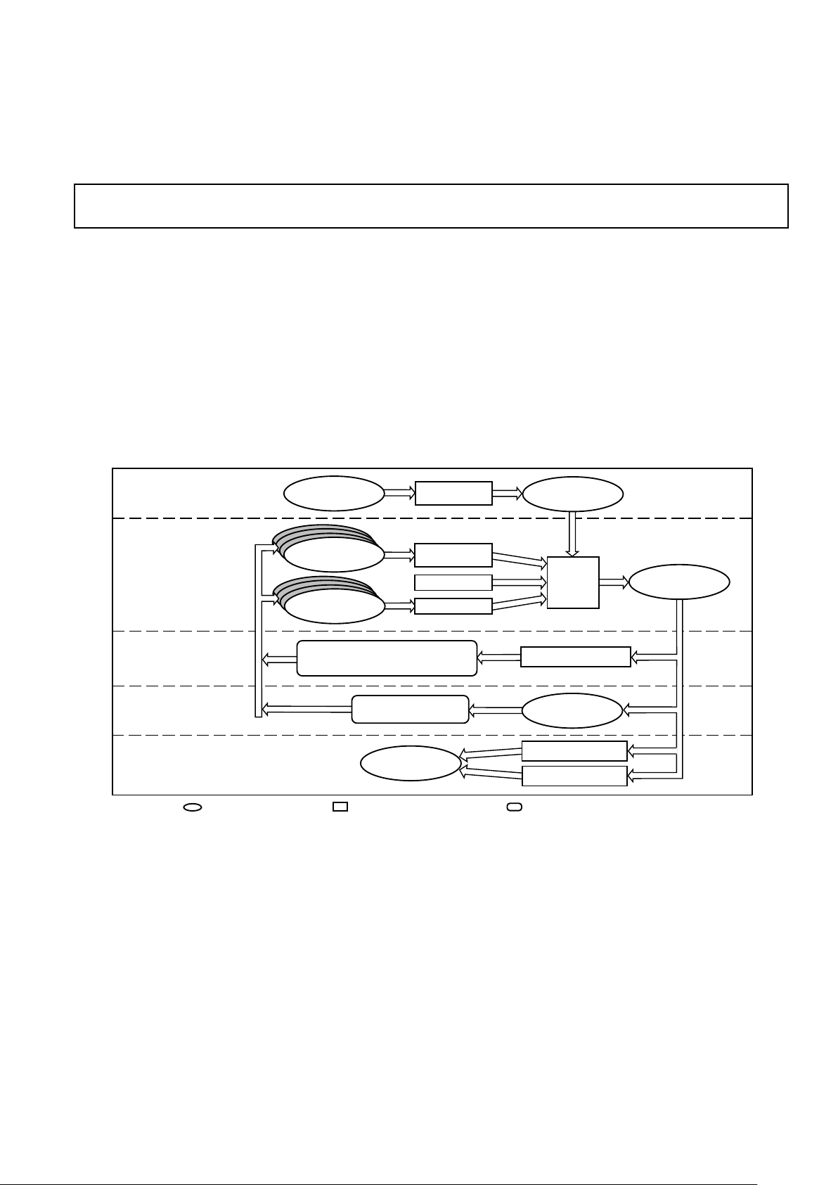
SYSTEM DEVELOPMENT PROCESS OVERVIEW
SOFTWARE SIMULATOR
LIBRARIES
ANSI
C COMPILER
ASSEMBLER
LINKER
EZ-ICE EMULATOR
= USER FILE OR HARDWARE
= SOFTWARE DEVELOPMENT TOOL = HARDWARE DEVELOPMENT TOOL
STEP 1:
DESCRIBE
ARCHITECTURE
STEP 2:
GENERATE
CODE
STEP 3:
DEBUG
SOFTWARE
STEP 4:
DEBUG IN TARGET
SYSTEM
STEP 5:
MANUFACTURE
FINAL SYSTEM
SYSTEM
BUILDER
PROM SPLITTER
HIP SPLITTER
SYSTEM
ARCHITECTURE
FILE
EXECUTABLE
FILE
SYSTEM
SPECIFICATION
FILE
C SOURCE
FILES
ASSEMBLER
SOURCE
FILES
EZ-LAB DEVELOPMENT BOARD
OR
THIRD-PARTY PC PLUG-IN CARDS
TARGET
BOARD
TESTED &
DEBUGGED
DSP BOARD
ADDS-21xx-TOOLS

REV. B
–2–
ADDS-21xx-TOOLS
SIMULATOR
Features Reconfigurable GUI (Graphical User Interface)
Supports Full Symbolic Disassembly and On-Line
Assembly
Provides Breakpoint and Single-Step Execution
Includes CBUG™ C Source-Level Debugger as Integrated
Tool
Supports Multiple Break Conditions
Provides Full View of All Processor Registers and
Memory for Direct Modification of Contents
Profiles Code Execution History
Uses Data Files to Simulate Parallel I/O Ports, Serial
Ports, HIPs, and Analog I/O Interface
Plots Data Memory Graphically
G21 OPTIMIZING C COMPILER & C RUNTIME LIBRARY
Compliant with ANSI C Standards
Includes C-Callable Library of ANSI-Standard and DSP
Functions
Supports In-Line Assembly Code Using asm () Construct
Incorporates Optimizing Algorithms
Generates Reliable and ROM-able Code
Simplifies Interrupt Handling via Library Functions
Provides Support for Heap Memory Management
Supports Switches Used by the ADSP-21000 Family
G21K Floating Point C Compiler
Supports Float Type IEEE-Single Precision Math Routines
CBUG C SOURCE-LEVEL DEBUGGER
Supports Single Step Execution
Supports Breakpoints
Integrated with Simulators and EZ-ICE Emulators
DEVELOPMENT HARDWARE TOOLS
EZ-LAB® EVALUATION BOARD
Complete Hardware Platform with Memory and I/O
Preprogrammed with DSP Demo Programs
Contains Audio/Voice I/O Port with Microphone Input
and Powered Output for Speaker
Memory Expansion and I/O from Bus Expansion Connector
Serial Port Interface via SPORT Connector
EZ-KIT STARTER PACKAGES
Complete Hardware and Software Development Kit
Includes an EZ-LAB Evaluation Board and ADSP-2100
Family Assembler/Linker and Simulator Software for
IBM PC
EZ-KIT LITE
Low Cost Development System
Including Hardware and Software
MS Windows 3.1 Based Monitor
Includes a Variety of Demonstration Programs with
Source Code
Development Platform for all ADSP-21xx Processors
Audio Input/Output and Expansion Connectors
EZ-ICE® EMULATOR
Performs Full-Speed, In-Circuit Emulation of ADSP-21xx
Target Systems
Software Uses Same GUI (Graphical User Interface) as
Simulator for Easier Debugging Control
Single-Step Capability
Stand Alone Operation for Software Debugging
Upload/Download Memory with IBM PC
3-VOLT EMULATION CONVERTER BOARD
Used with the ADSP-2101 EZ-ICE to Enable Emulation
with an ADSP-2103 (3 V) Target System
CBUG is a trademark of Analog Devices, Inc.
EZ-ICE and EZ-LAB are registered trademarks of Analog Devices, Inc

ADDS-21xx-TOOLS
REV. B
–3–
Introduction to Development Tools
GENERAL DESCRIPTION
The ADSP-2100 Family Development Software, a complete set
of software design tools, lets you program applications for this
family of DSP microprocessors that includes the ADSP-2101,
ADSP-2105, ADSP-2111, ADSP-2115, and the newest
members, the ADSP-2171 and ADSP-2181. With these tools,
an EZ-ICE In-Circuit Emulator, and an EZ-LAB Evaluation
Board, you can quickly and efficiently design your DSP
applications. The figure on page 1 (“System Development
Process Overview”) shows how the tools are typically used in
the development process.
DSP Software Development Tools
The software development tools include the following programs:
• System Builder • G21 C Compile
• Assembler • C Runtime Library
• Linker • CBUG C Source-Level Debugger
• Simulator • PROM Splitter
The System Builder reads your system specification file and
then generates an architecture description file that passes
information about your target hardware to the linker, simulator,
and emulator. Code generation begins with the creation of C
language and/or assembly language source code modules. These
modules are compiled/assembled separately and then linked
together to form an executable program (memory image file).
The highly readable algebraic syntax of the ADSP-2100 Family
instruction set eases programming in assembly language. Multiplyaccumulate instructions are written in the same manner as the
actual equation. For example, the algebraic statement
r = r + x*y
is coded in assembly language as
MR = MR + MX0*MY0.
The simulator configures program and data memory according
to the architecture description file and simulates the memorymapped I/O ports to let you debug your system and analyze its
performance. After simulating your system and software, use the
emulator with your prototype hardware to test circuitry, timing,
and real-time software execution. The PROM Splitter then
translates the linker-output executable file into an industrystandard file format for a PROM programmer. Once you burn
the code into a PROM device and plug in an ADSP-21xx
processor to the target board, your prototype is ready to run.
Development software is available for the IBM (or IBMcompatible) PC/AT and Sun4 workstation platforms.
DSP Hardware Development Tools
• EZ-ICE Emulators
• EZ-KIT Development Tools Packages
• EZ-LAB Evaluation Boards
The ADSP-2100 Family hardware development tools provide a
controlled environment for observing, debugging, and testing
activities in a full-speed target system. Our ADSP-2100 Family
EZ-ICE Emulators provide this control by replacing the target
processor or, in the case of the ADSP-2181, by assuming
control of the DSP through its ICE-Port. The EZ-ICE,
controlled by an IBM PC host computer, using a GUI interface
similar to the ADSP-2100 Family Simulators, lets you examine
and modify processor information such as registers and
memory.
The ADSP-2100 Family EZ-LAB Evaluation Boards let you test
coded applications in real time without a host or PC. At reset,
the processor on the ADSP-2100 Family EZ-LAB boots code
and program memory into its internal program memory from
the EPROM, and then executes the code.
EZ-KIT offers a complete development environment including
the ADSP-2100 Family Assembler/Linker and Simulator, an
ADSP-2100 Family EZ-LAB Evaluation Board. The EZ-KITs
for the ADSP-2101 and ADSP-2111 include an applications
handbook (Digital Signal Processing Applications Using the
ADSP-2100 Family Applications), plus a laboratory textbook
(Digital Signal Processing Laboratory Using the ADSP-2101
Microcomputer Laboratory Workbook with Introductory DSP
Experiments) and source code diskettes. The EZ-KIT Lite for
the ADSP-2181 is a lower cost starter kit that includes a subset
of the regular EZ-KIT software and documentation.
SOFTWARE TOOLS
SYSTEM BUILDER
The System Builder lets you define system hardware based on
ADSP-21xx processors with memory that can be specified as
RAM or ROM. It also lets you design ADSP-21xx Family
systems with paged external data memory, extending the
processor’s address space for additional data storage.
G21 C COMPILER
The G21 C Compiler is an optimizing ANSI compiler based on
the GNU gcc compiler. Applications written in C are compiled,
assembled, and linked to create executable ADSP-21xx
programs that can be debugged with an ADSP-21xx Simulator
or Emulator. It also supports in-line assembly code using the
asm() construct, which lets you use C expressions.
The G21 C Compiler contains optimization features to increase
execution speed of the resultant assembly code. These features
include algorithms to perform the following:
• Constant Folding
• Common Subexpression Elimination
• Loop Optimization and Strength Reduction
• Global and Local Register Allocation
• Parallelization
• Instruction Scheduling

REV. B
–4–
ADDS-21xx-TOOLS
C RUNTIME LIBRARY
The C Compiler comes with ANSI-standard functions and a set
of C-callable library routines commonly used in digital signal
processing to speed up development.
The ADSP-2100 Family C Runtime Library includes the ANSIstandard and DSP-specific functions listed in Table I.
Table I. C Runtime Library Functions
Function Description
abs absolute value
acos arc cosine
asin arc sine
atan arc tangent
atan2 arc tangent of quotient
ceil ceiling
cos cosine
cosh hyperbolic cosine
exp exponential
fabs absolute value
fir finite impulse response (FIR) filter
floor floor
fmod floating-point modulus
frexp separate fraction and exponent
ifftN N-point inverse fast Fourier transform (IFFT)
iir infinite impulse response (IIR) filter
interrupt define interrupt handling
isalpha detect alphabetic character
isdigit detect decimal digit
labs absolute value
ldexp multiply by power of 2
log natural logarithm
log10 base 10 logarithm
memcmp compare objects
memcpy copy characters from one object to another
memset set range of memory to a character
modf separate integral and fractional parts
pow raise to a power
raise force a signal
signal define signal handling
sin sine
sinh hyperbolic sine
sqrt square root
strcat concatenate strings
strcmp compare strings
strcpy copy from one string to another
strlen string length
strncat concatenate characters from one string to another
strncmp compare characters in strings
strncpy copy characters from one string to another
tan tangent
tanh hyperbolic tangent
timer_off disable ADSP-21xx timer
timer_on enable ADSP-21xx timer
timer_set initialize ADSP-21xx timer
va_arg get next argument in variable list
va_end reset variable list pointer
va_start set variable list pointer
Interrupt Handling in C
The C environment supports hardware interrupts—a key feature
that facilitates programming. The signal handling functions of
the C library, signal, raise, and interrupt, process
ADSP-21xx interrupts such as serial port transmit and receive
interrupts, timer interrupts, and external interrupt request
signals.
The signal and raise functions direct execution to a specific
C interrupt service routine based on the type of interrupt that
occurs. This routing service allows the entire application to
be written in C without assembly language code. The signal
handling routines save and restore registers, and the overhead is
usually minimal compared to overall program execution time.
If you choose to write custom interrupt service routines in
assembly language, you can use the signal and raise
functions to set up service routines in the C environment.
ASSEMBLER
The Assembler reads source files containing ADSP-2100 Family
assembly language and generates a relocatable object file. The
Assembler includes a preprocessor that lets you use C
preprocessor directives such as #define, #include, #if,
#ifdef, and #else in assembly code.
Assembler directives define code modules, data buffers, data
variables, and memory-mapped I/O ports. Either assembler
directives or C preprocessor directives define and invoke
macros.
LINKER
The Linker processes separately assembled object files to create
a single executable program. It assigns memory locations to
code and data in accordance with the architecture file defined
by the System Builder.
The Linker also generates symbols (variable names and program
labels) in the processed files, which the simulator, emulator, and
the CBUG C Source-level debugger use to perform symbolic
debugging.
PROM SPLITTER AND HIP SPLITTER
The PROM Splitter translates an ADSP-21xx executable
program into a file used to program PROM memory devices.
The PROM Splitter’s output file can be generated in Motorola
S Record or Intel Hex Record format. Motorola S2 format is
supported for byte stream output.
The HIP Splitter utility generates ADSP-2111 and ADSP-2171
programs to be downloaded from a host processor through the
DSP’s Host Interface Port (HIP). The HIP Splitter’s output file
can be generated in Motorola S Record or Intel Hex Record
format.
Both the PROM Splitter and the HIP Splitter have a boot
loader option that enables loading of external memory.
ADDS-21xx-TOOLS
REV. B
–5–
SIMULATORS
There is a simulator for each ADSP-2100 Family processor that
provides instruction-level simulation of program execution. The
Simulator models system memory and I/O according to the
contents of the system architecture file, and provides windows
to display different portions of the target system hardware. The
Graphical User Interface (GUI) lets system designers interactively observe and alter register and memory contents,
providing a powerful debug environment. Simulator commands
can be entered from the mouse or keyboard.
Features offered by the ADSP-2100 Family Simulators include
the following:
• Program and Data Memory Simulation
• Memory-Mapped I/O Port Simulation
• Interrupt Simulation
• Program Booting (from PROM or host processor) Simulation
• Code Execution Pattern Profiling for Program Optimization
• On-Line Help
• Reconfigurable Windows
• Same User Interface as EZ-ICE Emulators
CBUG C SOURCE-LEVEL DEBUGGER
The Simulators are seamlessly integrated with the CBUG C
source-level debugger. CBUG supports the following
operations:
• Run, Step, Next, and Finish Program Execution Commands
• C Source Code Breakpoints
• Local and Global Variable Display with Auto Refresh
Examines Value of Variables at Previously Executed
Instructions
• Symbol Look-Up
List of Demos
Filter
E
cho Canceller
A
DPCM
7
.8 kbs LPC
2
.4 kbs LPC
Ex
it App
D
TNF
F
ile View Demo Loading Options Help
EZ-KIT Lite - Monitor
P
D
DP
?
Ready
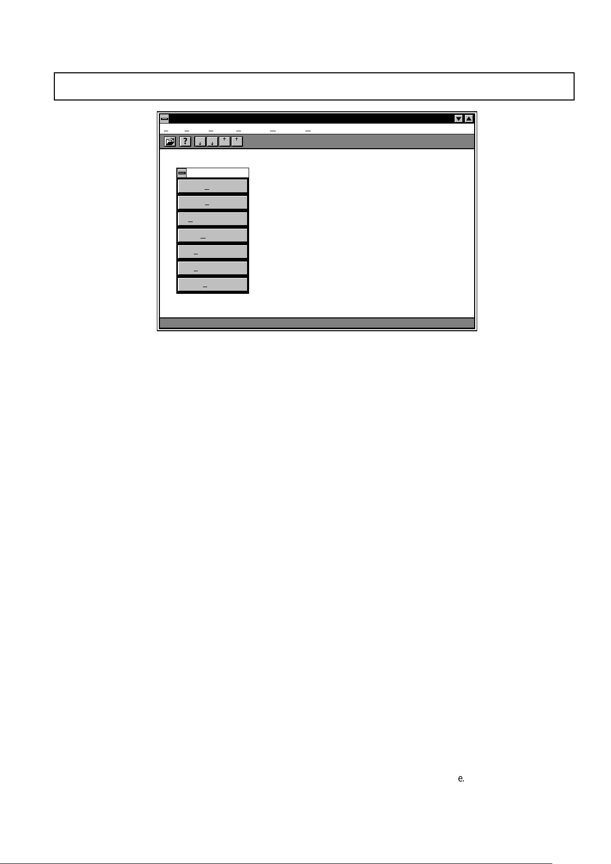
Figure 1. EZ-KIT Lite Monitor Software
HARDWARE TOOLS
EZ-KIT Lite
The ADSP-21xx EZ-KIT Lite is a low-cost, easy to use
development platform on which you can quickly get started with
your ADSP-2100 Family based DSP software design. The EZKIT Lite is a complete development system package that
includes:
• ADDS-2181 EZ-LAB Board
• MS-Windows 3.1 Based Monitor Software
• Development Software Kit (upgradable to complete ADSP2100 Family Development Software package for full-featured
development of final systems)
• Demo Programs
- Digital Filtering
- Speech Compression
- FFT
- Echo Cancellation
- DTMF Tone Generation
- MPEG Audio Playback
The EZ-Kit Lite uses the ADDS-2181 EZ-LAB as a
development platform on which you can develop software
applications for any of the ADSP-2100 Family DSPs. This is
possible because the ADSP-2181 represents a superset of the
features of the ADSP-2101/2105/2111/2115/2171 processors.
With the ADSP-2181’s 32K words of on-chip RAM, there is no
need for additional RAM devices on the EZ-LAB board. The
board simply requires connection to power, an analog input
source, and amplified speakers to be able to run audio
applications and demos.
The EZ-LAB board can run in a stand-alone mode, or it can be
connected to the RS-232 port of your PC. A Windows-based
monitor program lets you interactively download programs and
interrogate the ADSP-2181 (see Figure 1). The board comes
with a socketed EPROM so that you can run the monitor
program or demonstrations provided—or you can plug in an
EPROM containing your own code.

REV. B
–6–
ADDS-21xx-TOOLS
An AD1847 SoundPort® codec is connected to the DSP
through serial port 0. The AD1847’s sampling rate can be
programmed for analog-to-digital and digital-to-analog
conversion from 5.5 kHz to 48 kHz. The high-speed
synchronous serial port carries all of the data, control, and
status information between the DSP and the codec. The codec
may be disconnected from the serial port if the port is needed
for other purposes. Input to the codec can be a microphone,
signal generator, or any other high impedance source, while the
resulting output signal can drive an amplified speaker or the
line-level input of other audio equipment.
As with all EZ-LAB evaluation boards, the ADDS-2181 EZLAB provides a manual power-on reset button, an interrupt
button, and an LED controlled by the FL1 Flagout pin.
Although the IDMA port on the ADSP-2181 is not used on the
EZ-LAB board, all of the IDMA signals are available through
an expansion connector.
Device Specific EZ-KITs
Two other EZ-KITs are available for specific members of the
ADSP-21xx Family.
ADSP-2101 EZ-KIT
The ADSP-2101 EZ-KIT is a starter package for system
development that combines the ADSP-2101 EZ-LAB with an
Assembler software package and a Simulator. This EZ-KIT
may also be used for developing applications targeting the
ADSP-2105 and ADSP-2115 processors.
ADSP-2111 EZ-KIT
The ADSP-2111 EZ-KIT is a starter package for ADSP-2111based system development that combines the ADSP-2111 EZLAB with an Assembler software package and a Simulator.
ADSP-2100 FAMILY EZ-LAB EVALUATION BOARDS
The ADSP-2100 Family EZ-LAB Evaluation Boards are a
complete DSP system on a single board that lets you test coded
applications in real time. Some EZ-LABs provide for booting
from EPROM and others allow upload/download capabilities
from a host PC. Table II lists the features of the different
versions of the EZ-LAB available for the ADSP-2100 family.
ADSP-2181 EZ-LAB
See the discussion of the ADSP-21xx EZ-KIT Lite for
information on the ADSP-2181 EZ-LAB.
ADSP-2101 & ADSP-2111 EZ-LABs
The ADSP-2101 and ADSP-2111 EZ-LABs are similar in
design and use. A complete DSP system on a single board, the
EZ-LAB lets you test coded applications in real time without an
external host. At reset, the processor on the EZ-LAB boots
code and programs memory data into its internal program
memory from a 64K × 8-bit EPROM and then executes the
code.
The ADSP-2101 and ADSP-2111 EZ-LAB provide manual
control of several functions. For example, push-buttons activate
the IRQ2 interrupt and FLAG IN pins, and an on-board
hardware RESET switch resets the EZ-LAB.
In addition to the standard features of the ADSP-2101, the
ADSP-2111 includes a Host Interface Port (HIP) that is also
included on the ADSP-2111 EZ-LAB board as a separate
connector. The ADSP-2111 EZ-LAB board replaces the
ADDS-2101’s User Interface Connector with an Expansion
Connector that allows access to the external address and data
bus and control lines of the DSP.
The demonstration boards operates alone when you attach them
to a +5 V dc @ 1 amp and ±12 V dc power supply with a
common power return.
Demo Programs
Use the prepared demonstrations on the ADSP-2101 and
ADSP-2111 EZ-LABs, which include speech and graphics
applications, to familiarize yourself with and to evaluate the
ADSP-2100 Family processors. The EPROM is mapped into
the boot memory space. Upon reset, the processor loads boot
page 0 into its internal program memory and begins execution.
During program execution, any one of the eight boot pages can
be loaded into the processor under software control.
The demonstrations use the microphone and speaker
connections for audio input and output. The ADSP-2101 and
ADSP-2111 EZ-LABs have four DAC outputs to connect to an
oscilloscope for display. In addition to these outputs, these EZLABs have an expansion connector and a serial port connector
for synchronous serial data I/O. The connectors let you access
the serial ports, external address bus, external data bus, control
signals, interrupt lines, and the host interface port.
Analog I/O
A codec attaches to the processor’s serial port 0 on the ADSP2101 and ADSP-2111 EZ-LABs. Configure the other serial
port for interrupts and flags by changing on-board jumpers. The
input signal to the codec can be a microphone, signal generator
or any other high impedance source, and the resulting output
signal can drive a small speaker.
The ADSP-2101 EZ-LAB and ADSP-2111 EZ-LABs contain
socket-mounted 16.384 MHz crystals. The socket lets you
replace the crystal to achieve different clock speeds.
ADSP-2105 and ADSP-2115 System Development
The ADSP-2101 EZ Development Tools support the ADSP2105 and the ADSP-2115 because their architectures are
subsets of the ADSP-2101. The ADSP-2105 has one serial port
(instead of two), and both the ADSP-2105 and the ADSP-2115
have half the internal memory of the ADSP-2101. Use the
ADSP-2101 EZ-LAB to evaluate, and the ADSP-2101 EZ-ICE
for emulation and debugging of both the ADSP-2115 and
ADSP-2105 target systems.
The ADSP-2171 EZ-LAB
The ADSP-2171 EZ-LAB is an easy to use hardware
development platform on which you can quickly get started with
your ADSP-2171-based application. Applications can be run in
real-time with or without a PC host. This EZ-LAB has four
modes of operation:
• EZ-LAB can be controlled from your PC host when the
board is plugged into the PC backplane; programs can be
downloaded and uploaded, the processor can be reset, and
program execution can be initiated.
• EZ-LAB can be interfaced to an EZ-ICE Emulator; through
the EZ-ICE, programs can be loaded into EZ-LAB, program
execution can be initiated and halted, register and memory
locations can be examined and altered, and other debugging
operations can be performed.
SoundPort is a registered trademark of Analog Devices, Inc

ADDS-21xx-TOOLS
REV. B
–7–
Table II. ADSP-2100 Family EZ-LAB Evaluation Boards
Features
For Use with These DSPs ADSP-2101 ADSP-2111 ADSP-2171 ADSP-2181
ADSP-2105
ADSP-2115
ADSP-216x
DSP Clock Frequency 12.5 MHz 13 MHz 33 MHz 33 MHz
EZ-LAB Firmware ✓✓✓✓
Windowed Software with GUI Interface ✓✓✓✓
Context Sensitive Help ✓✓✓✓
Bundled Software Development Tools ✓
Stand-Alone Operation ✓✓✓✓
IBM-PC/AT Plug-In Board Operation ✓
On-Board DSP Performance 16 MIPS 16 MIPS 33 MIPS 33 MIPS
Boot EPROM 64K × 8 64K × 8 64K × 8 64K × 8
DSP Internal RAM (Program) 2K × 24 2K × 24 2K × 24 16K × 24
DSP Internal RAM (Data) 1K × 16 1K × 16 2K × 16 16K × 16
On-Board RAM 32K × 24*
Audio Input/Output Circuitry ✓✓✓✓
Configuration Jumpers ✓✓✓✓
LED Status Indicators ✓✓✓✓
Expandable to Full Program and Data Memory Capability ✓✓✓✓
Serial Port (SPORT) Connector ✓✓Note 1 Note 2
Manual Interrupt/Flag/Reset Switches ✓✓✓✓
Host Interface Port (HIP) Connector ✓✓
MAFE Interface ✓
EZ-ICE Connector ✓✓
Expansion Connector ✓✓✓✓
NOTES
* Optional
1
Available as part of MAFE connector; connector not installed.
2
Available through expansion connector.
ADSP-2101
EZ-LAB
ADSP-2111
EZ-LAB
ADSP-2171
EZ-LAB
ADSP-2181
EZ-KIT Lite

REV. B
–8–
ADDS-21xx-TOOLS
• EZ-LAB can be controlled from a host plugged into the Host
Interface Port (HIP) connector when the EZ-LAB is running
in a stand-alone configuration.
• EZ-LAB can be controlled from software contained in a boot
EPROM when the board is used in a stand-alone configuration.
The ADSP-2171 interfaces directly to its program and data
memories. The expansion connector may be used to interface
to external devices. The DSP is also connected to indicator
lights for data output and to pushbuttons for manual data input.
Modular Analog Front End (MAFE) daughter cards can be
connected to the ADDS-2171’s MAFE Interface Connector,
allowing the DSP to communicate with a variety of I/O
peripherals through memory mapped registers.
Modular Analog Front End (MAFE)
The MAFE specification provides a standard configuration for
connecting analog I/O devices to MAFE compatible EZ-LAB
products. This specification is used by Analog Devices and
third-party vendors to design and manufacture add-on adapters
which contain, for example, A/D and D/A converters. These
A/D and D/A converters can communicate data either serially
or on a parallel bus. These devices can also contain a number
of internal control registers as well as some external control
lines.
If the MAFE device uses parallel data transfer, the memory
location designated as the MAFE data is written to or read from
in order to transfer data to/from the MAFE device. Data for a
control register and data which represents the analog sample are
both transferred in this manner. If the MAFE device uses a
serial data transfer, the appropriate serial port of the DSP is
used. Transfer of control data may also need to be done in a
parallel fashion.
ADSP-2100 Family EZ-ICE Emulators
The ADSP-2100 Family EZ-ICE in-circuit emulators are used
for testing and debugging an ADSP-21xx-based system. The
EZ-ICEs make it easy to view and manipulate the data needed
to debug your DSP applications. Table III lists the features of
each version of EZ-ICE currently available for the ADSP-2100
family.
Control and debug features include single-step capabilities, with
or without register displays, and multiple breakpoint selections.
At power-up, the host PC automatically resets and performs a
diagnostic check to ensure that both host memory and the EZICE are functional; it automatically displays any failures found.
ADSP-2181 EZ-ICE TOOLS
Features
The ADSP-2181 EZ-ICE In-Circuit is a development tool for
debugging programs running in real time on a target system
based on the ADSP-2181. It includes all of the standard
functionality of the other EZ-ICEs, with the added advantages
of full speed emulation, a smaller connector interface, and ease
of use.
The ADSP-2181 EZ-ICE provides a simpler target board
connection that requires fewer mechanical clearance
considerations than other EZ-ICE Emulators by utilizing the
ICE-Port™ emulation interface built into the ADSP-2181 (see
Figure 3). The ICE-Port interface requires little more than a
14-pin header connector to implement it. All of the standard
functionality of the other EZ-ICEs are provided, with the added
advantages of full speed emulation, a very small connector
interface, and ease of use.
EZ-ICE Software
Like the rest of the ADSP-2100 Family EZ-ICE Emulators, the
ADSP-2181 uses the same EZ-ICE software and GUI interface
design as the other EZ-ICEs and the ADSP-2100 Family
Simulators. This makes the development process easier as the
tools share so much commonality in use.
ADSP-2101 AND ADSP-2111 EZ-ICE TOOLS
Features
These versions of the EZ-ICE are designed with a PGA
connector protruding from the bottom of the probe board that
fits into the processor socket on the target system. Connector
adaptors for PQFP and TQFP are available. The ADSP-2101
EZ-ICE is also used in developing systems based on the ADSP2105, ADSP-2115, and ADSP-216x DSPs. Systems based on
the ADSP-2111 use the ADSP-2111 EZ-ICE.
EZ-ICE Software
The ADSP-2101 and ADSP-2111 EZ-ICE Emulators use the
same EZ-ICE software and GUI interface design as all of the
ADSP-2100 Family EZ-ICEs and the ADSP-2100 Family
Simulators. Development productivity is increased by making
your data easier to view and manipulate when debugging. In
addition, you can view relevant information without switching
between screens and can obtain on-line help for the currently
selected window. The user interface is similar to the one used
with the ADSP-2100 Family Simulators, making both tools
easier to use.
ADSP-2171 EZ-ICE TOOL
Features
The ADSP-2171 EZ-ICE In-Circuit Emulator is a development
tool for debugging programs running in real time on a target
system based on the ADSP-2171 processor. This is made
possible through the use of the ADDS-21xx EZ-ICE Board
which differs from other EZ-ICE models in its use of a pair of
dedicated header connectors that allow it to plug directly onto
the target board and interface with the target DSP (see Figure
2) or to use an adaptor to clip onto the target DSP itself,
depending on the device package used.
EZ-ICE Software
Like the rest of the ADSP-2100 Family EZ-ICE Emulators, the
ADSP-2171 uses the same EZ-ICE software and GUI interface
design as the other EZ-ICEs and the ADSP-2100 Family
Simulators. This makes the development process easier as the
tools share so much commonality in use.
ICE-Port is a trademark of Analog Devices, Inc.

ADDS-21xx-TOOLS
REV. B
–9–
Table III. ADSP-2100 Family EZ-ICE Emulators
Features
For Use with These DSPs ADSP-2101
ADSP-2105
ADSP-2115
ADSP-216x ADSP-2111 ADSP-2171 ADSP-2181
Windowed GUI Interface Software ✓✓✓✓
User Breakpoints 30 30 30 30
Memory Plot ✓✓✓✓
Program Code Modification Directly in Memory Window ✓✓✓✓
Symbolic Debugging (CBUG) ✓✓✓✓
Context Sensitive On-Line Help ✓✓✓✓
Registers, Stacks, and Memory values may be examined
and altered ✓✓✓✓
View Relevant Data Without Switching Screens ✓✓✓✓
Overlay Memory ✓✓✓✓
Memory Plot ✓✓✓✓
Execute Instruction ✓✓✓✓
Macro Capability ✓✓✓✓
Command Aliasing ✓✓✓✓
Single Step/Full Speed Operation in Target ✓✓✓✓
Flag 0 Output (FL0) LED Indicator ✓
PC Upload/Download Functions ✓✓✓✓
Stand-Alone Operation ✓✓✓✓
In-Target Operation ✓✓✓✓
Non-Intrusive Target Connection ✓✓
ICE-Port™ Interface ✓
Connector Clip Snaps Over Target DSP Chip (PQFP) ✓
Target Board Connection Through DSP Processor Socket ✓✓
Plugs Onto Dedicated Target Connectors ✓✓
Separate Target Board Connector ✓
Adaptors Available ✓✓
ADSP-2101
EZ-ICE
ADSP-2111
EZ-ICE
ADSP-2171
EZ-ICE
ADSP-2181
EZ-ICE

REV. B
–10–
ADDS-21xx-TOOLS
EZ-ICE EMULATORS: SPECIAL CONSIDERATIONS
Connector Requirements
The PGA probe’s footprint that protrudes from the bottom of
the ADSP-2101 and ADSP-2111 EZ-ICE boards fits into the
DSP chip socket on your target system. Note that the socket
must allow sufficient clearance for the ADSP-21xx’s footprint.
The ADSP-2171 EZ-ICE attaches to the target DSP chip by
simply clipping over the PQFP package version of the DSP. An
alternate approach is needed for use with the TQFP package
version of the DSP. Because the TQFP packaged chip and its
leads are too small for a probe, the target board should include a
pair of header connectors to allow the EZ-ICE board to plug
directly onto it in order to interface with the DSP chip. Both
methods are illustrated in Figure 2.
PQFP ADAPTOR
ADSP-2171 TQFP TARGET BOARDADSP-2171 PQFP TARGET BOARD
ADDS-21xx EZ-ICE BOARD
CBA
JP3
JP1
11
0.200 (5.08)
0.333
(8.46)
0.300 (7.62)
MAX ONLY
CUSTOMER
TARGET BOARD
0.125 (3.18)
0.000 (0)
TYP
ALLOW 0.15 IN (30.81 mm)
CLEARANCE
ALL AROUND
FED
SW1
JP2
0.810
(20.57)
2.310
(58.67)
3.250
(82.55)
3.100
(78.74)
0.750
(19.05)
2.850 (72.39)
0.200
(5.08)
3.700 (93.98)
3.900 (99.06)
1.800 (45.72)
0.490
(12.45)
1.530 (38.86)
Figure 2. ADDS-2171 EZ-ICE Installation

ADDS-21xx-TOOLS
REV. B
–11–
An alternate approach is required for the TQFP chip package.
Because of the extremely low profile of the surface mount
TQFP package, it is not practical to use a snap-on adaptor or
probe. Thus, in order to use the EZ-ICE, it is necessary to
provide a pair of header connectors on the target board that the
ADDS-21xx EZ-ICE board can plug directly onto. Extra space
around the adaptor and extra through-holes to the PQFP
package are not required to let you use the same PCB in
production. Dimensional requirements for placing the headers
is also shown in Figure 2.
ADSP-2181
There is no need for a surface mount adaptor for the ADSP2181 EZ-ICE. Instead, the ICE-Port Emulator Interface allows
for a simple 14-pin connector interface between the target board
and the EZ-ICE.
DESIGNING AN EZ-ICE COMPATIBLE TARGET
SYSTEM FOR THE ADSP-2181 AND THE ADSP-2171
ADSP-2181 Target System Requirements
The ADSP-2181 has on-chip emulation support and a special
set of pins that interface to the EZ-ICE called the ICE-Port.
The ICE-Port allows in-circuit emulation without replacing the
target system’s processor or overriding it with a probe, requiring
only a simple 14-pin header connector to interface to the EZICE (see Figure 3).
Table IV lists the pins and functions used in the ADSP-2181’s
ICE-Port emulation interface.
Table IV. ADSP-2181 ICE-Port Emulation Interface
Pin Description
BR Bus Request
BG Bus Grant
RESET Reset
GND Ground
EBR Emulator Bus Request (emulator-only*)
EBG Emulator Bus Grant (emulator-only*)
ERESET Emulator Reset (emulator-only*)
EMS Emulator Memory Space (emulator-only*)
EINT Emulator Interrupt Request (emulator-only*)
ECLK Emulator Clock (emulator-only*)
ELIN Emulator Data In (emulator-only*)
ELOUT Emulator Data Out (emulator-only*)
EE Emulator Enable (emulator-only*)
NOTE
*These ADSP-2181 pins must be connected only to the ICE-Port connector in
the target system. These pins have no function except during emulation. Keep
all traces as short as possible; no longer than 3 inches.
GUI Interface
EZ-ICE software uses a Graphical User Interface (GUI) to
increase development productivity by making your data easier to
view and manipulate—without switching between screens—
when debugging. In addition, you can obtain on-line help for
the currently selected window. The GUI user interface design is
the same one used with the ADSP-2100 Family Simulator
software, making both tools easier to use.
Clock Speed
EZ-ICE runs at full speed. There is no degradation of
processor performance other than
BR, BG, and RESET, which
are slightly delayed. A jumper is used to select either the target
system clock or the EZ-ICE clock. The oscillator socket lets you
use other oscillator devices to achieve different clock speeds.
Memory
The ADSP-2101, ADSP-2111, and ADSP-2171 EZ-ICE each
have 8K × 24-bit overlay program memory and 16K × 16-bit
overlay data memory. You can either run programs from target
system memory, emulator overlay memory, or from a combination
of both. The overlay memory option is jumper-selectable.
Additional Equipment Required
EZ-ICE requires a +5 V dc power supply capable of supplying
1 A of current.
3-Volt Emulation
The 3-Volt Emulation Converter Board may be used with the
ADSP-2101 EZ-ICE to enable emulation of ADSP-2103 (3 V)
systems.
SURFACE MOUNT ADAPTORS
ADSP-2101/ADSP-2105/ADSP-2115
Several surface mount adaptors are available for emulation of
the ADSP-2101. For example: for the 68-pin PLCC package of
the ADSP-2101 and ADSP-2105, a PGA-to-PLCC adaptor is
available from the vendors listed at the end of this data sheet.
For the 80-pin PQFP package of the ADSP-2101, a 68-pin
PGA to 80-pin PQFP adaptor is also available.
The ADDS-2101-PGA/PQFP, a surface-mountable PGA-toPQFP adaptor, provides a footprint that exactly matches the 80pin package. This solution does not require extra space around
the adaptor or an extra through hole to the PQFP package to let
you use the same PCB in production. The PGA-to-PQFP
adaptor is surface mounted in the usual manner, and the PGA
connector of the ADSP-2101 EZ-ICE or ICE can be directly
plugged in.
ADSP-2111
The ADDS-2100-PGA/PQFP, a surface-mountable 101-pin
PGA to 100-pin PQFP adaptor, matches the ADSP-2111
package footprints. This solution does not require extra space
around the adaptor, and you can use the same PCB in
production. The PGA-to-PQFP adaptor is surface mounted in
the usual manner, and the PGA connector of the ADSP-2111
EZ-ICE can be directly plugged in.
ADSP-2171
The ADSP-2171 EZ-ICE Emulator is designed for compatibility with the surface mountable 128-pin PQFP package using an
adaptor card which plugs onto the ADDS-21xx EZ-ICE board
and then snaps onto the PQFP chip. This is illustrated in Figure
3. Extra space should be allowed around the PQFP chip to
allow clearance for the adaptor.

REV. B
–12–
ADDS-21xx-TOOLS
The EZ-ICE uses the ICE-Port’s EE (emulator enable) signal to
take control of the target ADSP-2181. This causes the DSP to
automatically use its
ERESET, EBR, and EBG pins instead of
the
RESET, BR, and BG pins. The BG output is tristated.
And, unlike many other emulators, these signals do not need to
be jumper-isolated in your system when the EZ-ICE is installed.
Restrictions
If you are using the external memory bus in your target system,
all memory strobe signals being used on the ADSP-2181 (
RD,
WR, PMS, DMS, BMS, CMS and IOMS) must have a 10kΩ
pull-up resistor connected when the EZ-ICE is being used. The
pull-up resistors are necessary because there are no internal
pull-ups to guarantee their state during prolonged tristate
conditions resulting from typical EZ-ICE debugging sessions.
These resistors may be removed at your option when the EZICE is not being used.
Interconnection
The EZ-ICE for the ADSP-2181 uses a 10-inch long ribbon
cable to connect to the target board. The ribbon cable is
permanently attached to the EZ-ICE and is terminated with a
standard 2-row × 7-pin (0.100 × 0.100 inch pin spacing) female
IDS connector. The mating ICE-Port connector on the target
board should be a 2-row × 7-pin male (0.025-inch square pins,
minimum 0.20-inches long) pin strip header (available from
such vendors as 3M, McKenzie, and Samtec). This connector
is necessary if you intend to use the ADSP-2181 EZ-ICE. The
length of traces between this connector and the DSP should be
kept as short as possible; no more than 3-inches long. Figure 4
shows the target board connector and the pin assignments. Pins
shown with a “*” notation must be connected only to the ICEPort connector.
1
2
3
4
56
7
8
9
10
1211
13
14
BG
BR
EINT
*
ELIN
*
ECLK
*
EMS
*
ERESET
*
GND
EBG
*
EBR
*
KEY (NO PIN)
ELOUT
*
EE
*
RESET
TOP VIEW
Figure 4. Target Board Connector for ADSP-2181 EZ-ICE
ADSP-2171 Target System Requirements
To provide emulator interface capability to your target DSP
board design, you must add a pair of 45-pin male headers to
your board. The EZ-ICE’s ADDS-21xx Emulator Board (EB)
plugs directly onto the connectors, becoming a daughter card
to your target system. Figure 2 shows how this is accomplished
and some of the critical dimensions involved. (Note: Pin strip
headers should be SAMTEC part number TSW-115-07-S-T
or equivalent.) It is important that there is approximately
0.40 inches clearance around the connectors.
ADDS-21xx EZ-ICE BOARD
ADSP-2181 CB BOARD
CUSTOMER ADSP-2181 TARGET SYSTEM
ICE-Port CONNECTOR
0.300 (7.62)
MAX ONLY
1.800 (45.72)
RIBBON CABLE
10 IN (254mm)
Figure 3. ADSP-2181 EZ-ICE Interface to Target System

ADDS-21xx-TOOLS
REV. B
–13–
Table VI. ADSP-2171 Emulator-Only Pins
Signal TQFP PQFP Pin
Name Pin Pin Description
EMMMAP 34 32 Emulator controlled MMAP
EBMODE 40 37 Emulator controlled BMODE
DF0 42 39 Emulator status pin
DF1 43 40 Emulator status pin
ERESET 47 44 Emulator controlled RESET
EE 65 62 Emulator enable
EINT 68 64 Emulator interrupt
EBR 69 65 Emulator controlled BR
EBG 71 67 Emulator controlled BG
XCYC 103 100 Emulator status pin
IADR 104 101 Emulator status pin
EMS 105 102 Emulator memory select
Do not connect a separate power supply to your EZ-ICE board
when it is inserted in your prototype through the emulator
connectors. The power connectors on the EZ-ICE EB board
are for stand-alone operation only.
(Note: For use in a stand-alone mode, a DSP target card is
supplied with the EZ-ICE and plugs onto the EZ-ICE through
the same pair of connectors described above.)
Also, while this scheme may be used for either the PQFP or
TQFP DSP packages, one alternative does exist for the PQFP
target system. This alternative involves a snap on PQFP
adaptor, also shown in Figure 1, that plugs onto the EZ-ICE EB
board and snaps onto the DSP chip.
Using EZ-LAB and EZ-ICE Together
Combining an EZ-LAB with an EZ-ICE forms a high speed
DSP evaluation and development environment with an
interactive, window-based debugging interface. For the ADSP2101 and ADSP-2111 EZ-LAB/EZ-ICE combinations, remove
the processor device from its socket on the EZ-LAB board and
plug the EZ-ICE into the DSP’s empty socket. For the ADSP2171 EZ-LAB/EZ-ICE combination, simply snap the EZ-ICE
with its PQFP adaptor onto the EZ-LAB’s processor. And for
the ADSP-2181 EZ-LAB/EZ-ICE combination, simply plug the
EZ-ICE’s ribbon cable connector onto the EZ-LAB’s ICE-Port
connector. These combinations let you prototype and evaluate
your application without initial time investment in hardware
design.
Table V lists the pinout for the female connectors on the EZICE’s EB board. See the ADSP-2171 Data Sheet for TQFP pin
locations, footprint, and mechanical information.
Table V. ADDS-21xx EZ-ICE EB Connector Pinout
Pin/
Row F E D C B A
1 VDD VDD NU NU VDD VDD
2 PWDAK GND BMS WR EMS*NU
3 XCYC* IADR* A0 PMS GND RD
4 A1 GND A2 D22 D23 DMS
5 A3 A4 A5 D20 GND D21
6 A6 GND A7 D17 D18 D19
7 NU NU CLKOUT D15 GND D16
8 A8 VDD A9 D12 D13 D14
9 A10 A11 A12 D10 D11
10 A13 GND NU D7 D8 D9
11 EMMAP* MMAP PWD D5 GND D6
12 EBMODE* BMODE NU D2 D3 D4
13 RESET GND ERESET* D0 GND D1
14 DF0* VDD DF1* EBR* VDD EBG*
15 NU GND EE* BR EINT*BG
Table VI lists the ADSP-2171’s emulator-only pins that
correspond to the EZ-ICE connector pins. These emulatoronly pins are listed on the ADSP-2171 data sheet as noconnects (NC). Also, note that the emulator-only pins must be
connected only from the DSP to the emulator connector. These
pins have no function except during emulation. Keep all
connections as short as possible. The scheme of mounting the
connectors on opposite sides of the DSP is best.
Do not connect a separate power supply to your EZ-ICE board
when it is inserted in your prototype through the emulator
connectors. The power connectors on the EZ-ICE EB board
are for stand-alone operation only.
(Note: For use in a stand-alone mode, a DSP target card is
supplied with the EZ-ICE and plugs onto the EZ-ICE through
the same pair of connectors described above.)
Also, while this scheme may be used for either the PQFP or
TQFP DSP packages, one alternative does exist for the PQFP
target system. This alternative involves a snap on PQFP
adaptor, also shown in Figure 1, that plugs onto the EZ-ICE EB
board and snaps onto the DSP chip

REV. B
–14–
ADDS-21xx-TOOLS
ADSP-2100 Family Ordering Guide
Ordering Information
Model Number Description
STARTER PACKAGES
ADDS-2101-EZ-KIT Starter Package: Assembler Package and Simulators,* ADSP-2101 EZ-LAB
ADDS-2111-EZ-KIT Starter Package: Assembler Package and Simulators,* ADSP-2111 EZ-LAB
ADDS-21XX-EZLITE Starter Package: ADSP-21xx EZ-KIT Lite (includes ADSP-2181 EZ-LAB, monitor software)
SOFTWARE AND HARDWARE
ADDS-21XX-SW-PC Assembler Package and Simulators, and C Tools (for IBM PC)
ADDS-21XX-SW-SUN Assembler Package, Simulators,* and C Tools** (for the Sun4 )
ADDS-2101-EZ-ICE ADSP-2101 EZ-ICE Emulator
ADDS-2101-EZ-LAB ADSP-2101 EZ-LAB Evaluation Board
ADDS-2101-3V ADSP-2101 3-Volt Emulation Converter Board
ADDS-2111-EZ-ICE ADSP-2111 EZ-ICE Emulator
ADDS-2111-EZ-LAB ADSP-2111 Evaluation Board
ADDS-2171-EZ-ICE ADSP-2171 EZ-ICE Emulator (for TQFP)
ADDS-2171-EZ-ICE-P ADSP-2171 EZ-ICE Emulator (with PQFP Clip-On Adaptor)
ADDS-2171-EZ-LAB ADSP-2171 EZ-LAB Evaluation Board
ADDS-2181-EZ-ICE ADSP-2181 EZ-ICE Emulator
AVAILABLE FROM OTHER A comprehensive listing of additional hardware and software tools is available in the Analog
VENDORS Devices’ 1996 DSP Third Party Developer Directory.
NOTES
**Assembler, Assembly Library/Librarian, Linker, PROM Splitter, HIP Splitter, and ADSP-21xx Simulators.
**G21 C Compiler, C Runtime Library, and CBUG C Source-Level Debugger.

ADDS-21xx-TOOLS
REV. B
–15–
Accessories Available from Other Vendors:
Model Number Description / Vendor
68-PIN PGA-PLCC ADAPTOR (for ADSP-2101 and ADSP-2105)
AP4-68-PGA Emulation Technology
2344 Walsh Avenue, Bldg. F
Santa Clara, CA 95051
(408) 982-0660
68-PGA/PLCC EDI Corporation
P.O. Box 366
Patterson, CA 95363
(209) 892-3270
68-PGA/PLCC McKenzie Technology
910 Page Avenue
Fremont, CA 94538-7340
(510) 651-2700
ADSP-2101 68-PIN PGA to 80-PIN PQFP ADAPTOR (for ADSP-2101 EZ-ICE)
AS-V143S Emulation Technology
2344 Walsh Avenue, Bldg. F
Santa Clara, CA 95051
(408) 982-0660
RAM EXPANSION CARD The RAM Expansion card expands the amount of program and data RAM available to the maximum
FOR THE EZ-LAB amount each DSP can address. The card also provides a user prototype area which includes four (4)
(for ADSP-2101 fully coded block select lines for addressing the expansion area, and all DSP signals are brought out to
and ADSP-2111) an expansion header for easy connection. You may also load a boot program into RAM and then restart
the DSP without reprogramming the EPROM.
Available from: Momentum Data Systems
1520 Nutmeg Place #108
Costa Mesa, CA 92626
(714) 557-6884 fax (714) 557-6969
PC INTERFACE CARD The PC Interface card lets you use an IBM compatible computer as a host for the DSP and RAM
FOR THE EZ-LAB expansion cards. Using the Bus Request and Bus Grant signals, the PC gains access to the RAM and
prototype expansion areas. The PC can interrupt the DSP, and the DSP can interrupt the PC via a
communication register. This register enables signaling from the DSP to the PC without slowing down
the DSP for bus accesses to check status. The card also provides access to the boot section of the
expansion card for downloading programs and restarting the DSP so the developer can design and test
programs without needing to burn EPROMs.
Available from: Momentum Data Systems
1520 Nutmeg Place #108
Costa Mesa, CA 92626
(714) 557-6884 fax (714) 557-6969
LAB+ FOR The LAB+ Enhancement Board, designed specifically for the ADSP-2101 EZ-LAB, provides a full
ADSP-2101 complement of external program and data RAM. As a low cost alternative to an in-circuit emulator,
EZ-LAB EVALUATION LAB+ contains a dual UART with RS-232 drivers that enable a Host PC communication link with the

C1873a–10–7/95
PRINTED IN U.S.A.
–16–
 Loading...