

V
www.BDTIC.com/ADI
500 MHz Dual DCL
FEATURES
Driver, comparator, and active load
500 MHz toggle rate
Inhibit mode function
Dynamic clamps
Operating voltage range: −1.5 V to 6.5 V
Output voltage swing: 200 mV to 8 V
Four range adjustable slew rate
True/complement data mode bit
100-lead TQFP package, exposed pad
Low per channel power
1.4 W with load off
1.75 W with load programmed at 20 mA nominal
Low leakage (<10 nA) in High-Z mode
Driver
50 Ω output resistance
1 ns minimum pulse width for a 3 V step
Load: −35 mA to +35 mA maximum current range
APPLICATIONS
Automatic test equipment
Semiconductor test systems
Board test systems
Instrumentation and characterization equipment
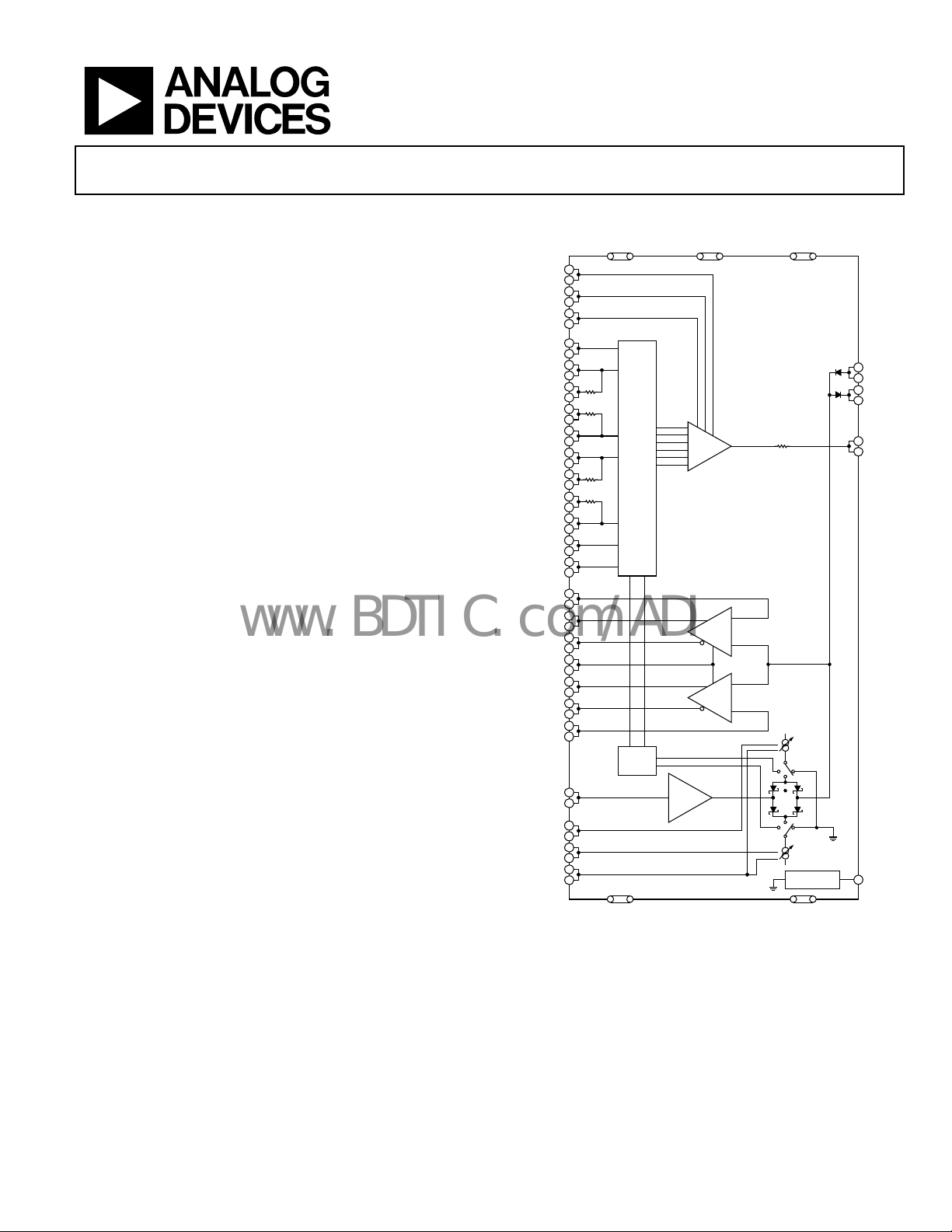
GENERAL DESCRIPTION
The ADATE206 is a complete, single-chip solution that
performs the pin electronics functions of driver, comparator,
and active load (DCL) for ATE applications. The active load can
be powered down if not used.
The driver is a proprietary design that features three active
modes: data high mode, data low mode, and term mode, as
well as an inhibit state. The driver has low leakage (<10 nA) in
High-Z mode. The output voltage range is −1.5 V to +6.5 V to
accommodate a wide variety of test devices.
The ADATE206 supports four programmable Tr/Tf times for
applications where slower edge rates are required. The edge rate
selection is done via two static digital CMOS select bits. The
input data to the driver can be inverted using a single CMOS
logic bit. This feature can be used for system calibration or
applications where complement input data is needed.
DR_INV
DR_DATA_P
DR_DATA_P_T
DR_DATA_N_T
DR_DATA_N
DR_EN_P
DR_EN_P_T
DR_EN_N_T
DR_EN_N
VTEN
LDEN
COMP_H_P
COMP_H_N
CLLM
COMP_L_P
COMP_L_N
VCOM
VIOL
VIOH
GNDREF
FUNCTIONAL BLOCK DIAGRAM
(18, 19, 57, 58 , 77, 78, 89, 98, 99)
7
VIT
69
8
VIL
68
9
VIH
67
6
70
22
54
23
53
24
52
25
51
26
50
27
49
28
48
29
47
15
61
14
62
91
CVH
85
31
45
32
44
13
63
34
42
35
41
90
CVL
86
1
75
4
72
3
73
2
74
VEE
(16, 17, 33, 43 , 59, 60, 84, 87, 92)
CC
LOGIC
LOAD
LOGIC
NC
(30, 46)
DRIVER
COMP_H
COMP_L
1x
(5, 12, 20, 21, 36, 40, 55, 56, 64, 71, 76, 79, 83, 93, 97,100)
Figure 1.
ADATE206
SHIELDS
(80, 82, 94, 96)
ADATE206
10
CLAMPL
65
11
CLAMPH
66
81
DUT
95
IOL
IOH
TEMP SENSOR
(5 DIODES)
GND
TEMP
88
05738-001
Rev. A
Information furnished by Analog Devices is believed to be accurate and reliable. However, no
responsibility is assumed by Analog Devices for its use, nor for any infringements of patents or other
rights of third parties that may result from its use. Specifications subject to change without notice. No
license is granted by implication or otherwise under any patent or patent rights of Analog Devices.
Trademarks and registered trademarks are the property of their respective owners.
One Technology Way, P.O. Box 9106, Norwood, MA 02062-9106, U.S.A.
Tel: 781.329.4700 www.analog.com
Fax: 781.461.3113 ©2006–2008 Analog Devices, Inc. All rights reserved.

ADATE206
www.BDTIC.com/ADI
TABLE OF CONTENTS
Features .............................................................................................. 1
Absolute Maximum Ratings ............................................................8
Applications ....................................................................................... 1
General Description ......................................................................... 1
Functional Block Diagram .............................................................. 1
Table of Contents .............................................................................. 2
Revision History ............................................................................... 2
Specifications ..................................................................................... 3
Electrical Characteristics ............................................................. 3
REVISION HISTORY
10/08— Rev. 0 to Rev. A
Changes to the VCOM Buffer Offset Parameter, Table 1 ............ 7
1/06— Revision 0: Initial Version
ESD Caution...................................................................................8
Pin Configuration and Function Descriptions ..............................9
Typical Performace Characteristics ............................................. 12
Theory of Operation ...................................................................... 15
Outline Dimensions ....................................................................... 16
Ordering Guide .......................................................................... 16
Rev. A | Page 2 of 16
ADATE206
www.BDTIC.com/ADI
SPECIFICATIONS
ELECTRICAL CHARACTERISTICS
VCC = 10.0 V, VEE = −5.0 V, TJ = 75°C, unless otherwise noted.
Table 1.
Parameter Min Typ Max Unit Test Conditions/Comments
DRIVER
Single-Ended Logic Input Characteristics
(VTEN, DRV_INV)
Threshold Voltage CMOS_VDD/2 V
Voltage Range 0 5.5 V
Bias Current −10 +10 μA VIN = 0 V, 3.3 V
Single-Ended Logic Input Characteristics
(SLEW0, SLEW1)
Threshold Voltage CMOS_VDD/2 V
Voltage Range 0 5.5 V
Bias Current −10 +600 (@ 3.3 V) +800 μA VIN = 0 V, 3.3 V
Bias Current 1 mA VIN = 5.5 V
Differential Logic Input Characteristics
(DR_DATA_N, DR_DATA_P, DR_EN_N,
DR_EN_P)
Voltage Range −2.0 +3.5 V
Differential Voltage with LVPECL Levels ±250 ±300 mV
Bias Current −10 +2 +10 μA VIN = 3.24 V, 3.495 V
VIH, VIL Reference Inputs
Input Bias Current −10 −2 +10 μA
VIT Reference Inputs
Input Bias Current −25 +12 +25 μA
DC Output Characteristics
Logic Range, VIL, VIH, VIT −1.5 +6.5 V
Amplitude [VH to VL] 8 V
Output Resistance 47.5 52.5 Ω
PSRR, Drive or Term Mode 10 mV/V VCC, VEE ±1%
Static Current Limit −125 ±110 +125 mA
Absolute Accuracy—VIH, VIL, VIT
VIH Offset −100 +30 +100 mV
VIH Gain Error 0.98 1.02 V/V
VIH Linearity Error −15 +5 +15 mV
VIL Offset −100 +30 +100 mV
VIL Gain Error 0.98 1.02 V/V
VIL Linearity Error −15 +5 +15 mV
VIT Offset −100 +30 +100 mV
VIT Gain Error 0.98 1.02 V/V
Maximum value bias of
reference sweep
Maximum value bias of
reference sweep
Output to −1.5 V, VH = 6.5 V,
VT = 0 V
Data = H, VH = 0 V, VL = −1.5 V,
VT = 3 V
Data = H, VH = 0 V to 5 V,
VL = −1.5 V, VT = 3 V
Data = VH relative to line
between 0 V to 5 V; full range of
VIH = −1.4 V to +6.5 V
Data = L, VL = 0 V to 5 V,
VH = 6.5 V, VT = 3 V
Data = VH relative to line
between 0 V to 5 V; full range of
VIH = −1.4 V to +6.5 V
Data = VT, VT = 0 V, VL = 0 V,
VH = 3 V
Data = VT, VT = 0 V to 5 V,
VL = 0 V, VH = 3 V
Rev. A | Page 3 of 16
ADATE206
www.BDTIC.com/ADI
Parameter Min Typ Max Unit Test Conditions/Comments
VIT Linearity Error −15 +5 +15 mV
Offset Tempco 80 μV/°C 65°C to 105°C
Driver Interaction
VH Interaction to VL −2 +2 mV
VH Interaction to VT −2 +2 mV
VL Interaction to VH −2 +2 mV
VL Interaction to VT −2 +2 mV
VT Interaction to VH −2 +2 mV
VT Interaction to VL −2 +2 mV
Rise/Fall Times at Device Under Testing (DUT)
0.2 V Swing: Rise/Fall Time 300 ps
0.5 V Swing: Rise/Fall Time 350 ps
1 V Swing: Rise/Fall Time 500 ps
3 V Swing: Rise/Fall Time 650 ps
3 V Swing: Rise/Fall Time 350 450 550 ps
5 V Swing: Rise/Fall Time 1.1 ns
Minimum Pulse Width at DUT
500 mV Swing
1.5 V Swing
1
500 ps
1
800 ps
Toggle Rate @ 3 V 500 MHz
Dynamic Performance, Drive (VH and VL)
Propagation Delay Time
Propagation Delay Tempco
2
1.4 ns
2
2.0 ps/°C
Delay Matching, Edge-to-Edge 20 ps
Delay Change vs. Pulse Width
Delay Change vs. Duty Cycle
2
30 ps
2
5 ps
Rev. A | Page 4 of 16
Data = VH relative to line
between 0 V to 5 V; full range of
VIH = −1.4 V to +6.5 V
VIH = 5.0 V; VIL = −1.5 V, +4.7 V,
+4.8 V, +4.9 V
VIH = 3.0 V; VIT = −1.5 V, +2.9 V,
+3.1 V, +6.5 V
VIL = 0.0 V; VIH = 0.1 V, 0.2 V,
0.3 V, 6.5 V
VIL = 0.0 V; VIT = −1.5 V, −0.1 V,
+0.1 V, +6.5 V
VIT = 1.5 V, VIL = −1.0 V;
VIH = −0.8 V, +1.4 V, +1.6 V,
+6.5 V
VIT = 1.5 V, VIH = 6.0 V; IL = −1.5
V, +1.4 V, +1.6 V, +5.8 V
Terminated 20% to 80%,
VIH = 400 mV, VIL = 0 V, VIT = 0 V
Terminated 10% to 90%,
VIH = 1.0 V, VIL = 0 V, VIT = 0 V
Terminated 10% to 90%,
VIH = 2.0 V, VIL = 0 V, VIT = 0 V
Unterminated 10% to 90%,
VIH = 3.0 V, VIL = 0 V, VIT = 0 V
Terminated 20% to 80%,
VIH = 3.0 V, VIL = 0 V, VIT = 0 V
using DUT comparator
Unterminated 10% to 90%,
VIH = 5.0 V, VIL = 0 V, VIT = 0 V
Terminated, VIH = 1.0 V, VIL = 0 V,
VIT = 0 V
Terminated, VIH = 3.0 V, VIL = 0 V,
VIT = 0 V
Unterminated, 50/50 dc
measured frequency when
amplitude drops 10%
Terminated, VIH = 3.0 V,
VIL = 0.0 V, VIT = 0.0 V
Terminated, VIH = 3.0 V,
VIL = 0.0 V, VIT = 0.0 V,
65°C to 85°C
Terminated, VIH = 3.0 V,
VIL = 0.0 V, VIT = 0.0 V, 1μs
period, pulse width = 50 ns
to 1 ns
Terminated, VIH = 3.0 V,
VIL = 0.0 V, VIT = 0.0 V, 1 μs
period; 10%, 50%, and 90% duty
cycle
ADATE206
www.BDTIC.com/ADI
Parameter Min Typ Max Unit Test Conditions/Comments
Settling Time to 15 mV 8 ns
Settling Time to 4 mV 32 ns
Rise and Fall Time Temperature Coefficient
500 mV Swing 2 ps/°C
1 V Swing 2 ps/°C
3 V Swing 2 ps/°C
5 V Swing 2 ps/°C
Overshoot and Preshoot 200 mV swing 1 % Terminated, VIH = 400 mV
Overshoot and Preshoot 1 V swing 1 % Terminated, VIH = 2 V
Overshoot and Preshoot 3 V swing 2 % Unterminated
Overshoot and Preshoot 5 V swing 2 % Unterminated
Dynamic Performance, Inhibit
Delay Time, Active High to Inhibit
Delay Time, Active Low to Inhibit
Delay Time, Inhibit to Active High
Delay Time, Inhibit to Active Low
3
3.1 ns
3
2.1 ns
3
2.5 ns
3
3.9 ns
I/O Spike 350 mV
CLAMPS
VCPH, VCPL Clamp Inputs
VCPH Voltage Range CLAMPL 6.8 V
VCPL Voltage Range −1.8 CLAMPH V
Input Bias Current −50 −2 +50 μA
Absolute Accuracy VCPH, VCPL
VCPH Offset −100 +55 +100 mV Driver = INH, VCPH = 0 V
VCPH Gain Error 1 V/V
VCPH Linearity Error +10 mV
VCPL Offset −100 +55 +100 mV Driver = INH, VCPL = 0 V
VCPL Gain Error 1 V/V
VCPL Linearity Error +10 mV
COMPARATOR DC SPECIFICATIONS
4
DC Input Characteristics (VOH, VOL)
Bias Current −10 +5 +10 μA VOH and VOL = −1.5 V to +6.5 V
Voltage Range −1.5 +6.5 V
Differential Voltage −8.0 +8.0 V
Rev. A | Page 5 of 16
Terminated, VIH = 3 V,
VIL = 0.0 V, VIT = 0.0 V
Terminated, VIH = 3 V, VIL = 0.0 V,
VIT = 0.0 V
Terminated 10% to 90%,
VIH = 1.0 V, VIL = 0.0 V,
VIT = 0.0 V, 65°C to 85°C
Terminated 10% to 90%,
VIH = 2.0 V, VIL = 0.0 V,
VIT = 0.0 V, 65°C to 85°C
Unterminated 10% to 90%,
VIH = 3.0 V, VIL = 0.0 V,
VIT = 0.0 V, 65°C to 85°C
Unterminated 10% to 90%,
VIH = 5.0 V, VIL = 0.0 V,
VIT = 0.0 V, 65°C to 85°C
Terminated, VIH = 3.0 V,
VIL = −1.0 V
VH = 3.0 V, VL = −1.0 V,
terminated 50 Ω
Terminated, VIH = 3.0 V,
VIL = −1.0 V
Terminated, VIH = 3.0 V,
VIL = −1.0 V
Terminated, VIH = 0.0 V,
VIL = 0.0 V, VIT = 0.0 V
Maximum value bias of
reference sweep = −1.8 V to
+6.8 V
Driver = INH, relative to line
between 0 V to 4.5 V,
VCPH = −1.5 V to +6.5 V,
VCPL = −1.8 V
Driver = INH, relative to line
between 0 V to 4.5 V,
VCPL = −1.5 V to +6.5 V,
VCPH = 6.5 V

ADATE206
www.BDTIC.com/ADI
Parameter Min Typ Max Unit Test Conditions/Comments
Offset −15 +15 mV Common mode = 0 V
Gain Error 1 % FSR VIN = −1.5 V to +6.5 V
Linearity Error 3 mV VIN = −1.5 V to +6.5 V
Single-Ended Logic Input Characteristics
Threshold Voltage (CLLM) CMOS_VDD/2 V
Voltage Range 0 5.5 V
Bias Current −10 +160 +200 μA VIN = 0 V, 3.3 V
Bias Current 260 μA VIN = 5.5 V
Digital Output Characteristics
(VOH, VOL Levels)
Logic 1 3.1 3.26 3.4 V Terminated 50 Ω to 3.3 V
Logic 0 2.7 2.86 3.1 V Terminated 50 Ω to 3.3 V
Differential Levels 350 400 450 mV Terminated 50 Ω to 3.3 V
COMPARATOR AC SPECIFICATIONS
Propagation Delay
Input to Output 500 ps VIN = 3 V p-p, 2 V/ns
Propagation Delay Tempco 1.0 ps/°C VIN = 3 V p-p, 2 V/ns
Propagation Delay Change with Respect to
PD vs. Duty Cycle 40 ps
Slew Rate: 1 V/ns, 2 V/ns, 3 V/ns 30 ps
Amplitude: 500 mV, 1.0 V, 3.0 V 30 ps
Equivalent Input Rise Time 225 ps
Pulse-Width Linearity 20 ps
Settling Time 5.5 ns
Minimum Pulse Width 1 ns
Hysteresis 6 mV
Comparator Propagation Delay Matching,
HCOMP to LCOMP
LOAD DC SPECIFICATIONS
Single-Ended Logic Input Characteristics
Threshold Voltage (LDEN) CMOS_VDD/2 V
Voltage Range 0 5.5 V
Bias Current −10 +10 μA VIN = 0 V, 3.3 V
Input Characteristics
VIOL Current Program Range 0.0 3.5 V
VIOH Current Program Range 0.0 3.5 V
VIOH, VIOL Input Bias Current −10 +10 μA
VDUT Range −1.5 +6.5 V |VDUT − VCOM| > 1.0 V
= 0 V to 3 V, 2 V/ns, driver in
V
IN
VTERM, VIT = 0 V, period = 10 ns;
dc = 1 ns, 5 ns, 9 ns
= 0 V to 3 V, driver in VTERM,
V
IN
VIT = 0 V
= 0 V to 500 mV, 0 V to 1 V, 0 V
V
IN
to 3 V, 2 V/ns, driver in VTERM,
VIT = 0 V
= 0 V to 1 V, <50 ps, 20% to
V
IN
80% rise time, driver in VTERM =
0 V
= 0 V to 3 V, 2 V/ns; pulse
V
IN
width = 3 ns, 4 ns, 5 ns, 10 ns;
driver in VTERM, VIT = 0 V
Settling to ±8 mV, V
3 V, driver in VTERM, VIT = 0 V
2 V terminated, 1 V at the
comparator, driver in VTERM,
VIT = 0 V, 1 μs period, pulse
width = 50 ns to 1 ns
= 100 mV, sweep CVL and
V
IN
CVH
50 ps
HCOMP rise to LCOMP rise,
HCOMP fall to LCOMP fall
VDUT = −1.5 V, +6.5 V;
IOL = 0 mA to 35 mA
VDUT = −1.5 V, +6.5 V;
IOH = 0 mA to 35 mA
VIOL = 0 V, 3.5 V;
VIOH = 0 V, 3.5 V
= 0 V to
IN
Rev. A | Page 6 of 16

ADATE206
www.BDTIC.com/ADI
Parameter Min Typ Max Unit Test Conditions/Comments
VDUT Range −1.5 +6.5 V
VDUT Range −1.5 +6.5 V
Output characteristics
Gain 9.5 10 10.5 mA/V
Load Offset, IOH, IOLT −200 +200 μA
Load Nonlinearity, IOH, IOLT −50 +50 μA
Output Current Tempco, IOH, IOLT ±3 μA/C Measured at IOH, IOL = 30 mA
VCOM Buffer (Through Bridge)
VCOM Buffer Offset −50 +3 +50 mV IOL, IOH = 20 mA, VCOM = 0 V
VCOM Buffer Bias Current −10 +1 +10 μA VCOM = −1.5 V to +6.5 V
VCOM Buffer Gain 0.99 1 1.01 V/V
VCOM Buffer Linearity Error −10 +1 +10 mV
Dynamic Performance
Propagation Delay—I
INHIBIT to I
2.3 ns
MAX
to INHIBIT 2.3 ns
MAX
TOTAL FUNCTION
Output Leakage Current −1.5 +0.28 +1.5 μA
Output Leakage Current, Low Leakage Mode −200 +10 +200 nA
Output Capacitance 2 pF
Power Supplies
5
Total Supply Range 15.5 V
Positive Supply, VCC 9.75 10.0 10.25 V
Negative Supply, VEE −5.25 −5.0 −4.75 V
Positive Supply Current, VCC 190 210 245 mA
Negative Supply Current, VEE 240 270 300 mA
Total Power Dissipation 2.5 3.5 4 W
Positive Supply Current Load Disabled, V
145 165 200 mA
CC
Negative Supply Current Load Disabled, VEE 190 220 250 mA
Total Power Dissipation 1.8 2.8 3.3 W
Temperature Sensor Gain Factor 10 mV/°C Five diodes in series
1
1 μs period, pulse width = 50 ns to 500 ps, pulse width measured when amplitude drops 10%.
2
Measured at 50% of input amp to 50% of output amp.
3
tPD measured from the 50% of enable signal to 50% of output.
4
The low leakage mode of the comparator, controlled by VLLM input, reduces the leakage due to the comparator input. The comparator operates in this mode, but its
bandwidth is compromised and is not guaranteed.
5
Under no circumstances should the input voltages exceed the supply voltages.
VDUT − VCOM > 1.0 V;
IOH = 0 mA to 35 mA
VCOM − VDUT > 1.0 V;
IOL = 0 mA to 35 mA
Slope of line between 5 mA and
30 mA
IOH and IOL programmed at
20 mV (200 μA)
Relative to a line from 5 mA to
30 mA; IOL, IOH from 200 μA to
35 mA
IOL, IOH = 20 mA,
VCOM = −1.5 V to +6.5 V
IOL, IOH = 20 mA,
VCOM = −1.5 V to +6.5 V, relative
to a line at 0 V and 5 V
VTT = 2 V, VCOM = 4 V/0 V,
IOL = 20 mA, IOH = 20 mA
VTT = 2 V, VCOM = 4 V/0 V,
IOL = 20 mA, IOH = 20 mA
Driver = INH, VDUT swept from
−1.5 V to +6.5 V
Driver = INH, VDUT swept from
−1.5 V to +6.5 V
Load enabled at 20 mA, driver is
set to VIL = 0 V
Load enabled at 20 mA, driver is
set to VIL = 0 V
Load enabled at 20 mA, driver is
set to VIL = 0 V
Load enabled at 0 mA, driver is
set to VIL = 0 V
Load enabled at 0 mA, driver is
set to VIL = 0 V
Load enabled at 0 mA, driver is
set to VIL = 0 V
Rev. A | Page 7 of 16

ADATE206
www.BDTIC.com/ADI
ABSOLUTE MAXIMUM RATINGS
Table 2.
Parameter Rating
Maximum Current for VCC 245 mA
Maximum Current for VEE 300 mA
Positive Supply Voltage (VCC to GND) +10.5 V
Negative Supply Voltage (VEE to GND) −5.5 V
Operating Temperature (Junction) +150°C
Storage Temperature Range −65°C to +150°C
ESD (Human Body Model) ±1500 V
ESD CAUTION
ESD (electrostatic discharge) sensitive device. Electrostatic charges as high as 4000 V readily accumulate on
the human body and test equipment and can discharge without detection. Although this product features
proprietary ESD protection circuitry, permanent damage may occur on devices subjected to high energy
electrostatic discharges. Therefore, proper ESD precautions are recommended to avoid performance
degradation or loss of functionality.
Stresses above those listed under Absolute Maximum Ratings
may cause permanent damage to the device. This is a stress
rating only; functional operation of the device at these or any
other conditions above those indicated in the operational
section of this specification is not implied. Exposure to absolute
maximum rating conditions for extended periods may affect
device reliability.
Rev. A | Page 8 of 16

ADATE206
www.BDTIC.com/ADI
PIN CONFIGURATION AND FUNCTION DESCRIPTIONS
GND99VCC98VCC97GND96GND/SHIEL DS95DUT_194GND/SHIEL DS93GND92VEE91CVH_190CVL_189VCC88TEMP87VEE86CVL_285CVH_284VEE83GND82GND/SHIEL DS81DUT_280GND/SHIEL DS79GND78VCC77VCC76GND
100
VCOM_1
GNDREF_1
VIOH_1
VIOL_1
GND
D_INV_1
VIT_1
VIL_1
VIH_1
CLAMPL_1
CLAMPH_1
GND
CLLM_1
LDEN_1
VTEN_1
VEE
VEE
VCC
VCC
GND
GND
DR_DATA_P_1
DR_DATA_P_T_1
DR_DATA_N_T_1
DR_DATA_N_1
1
PIN 1
2
3
4
5
6
7
8
9
10
11
12
13
14
15
16
17
18
19
20
21
22
23
24
25
26
27
28
29
30NC31
32
1DR_EN_N_T_
33
34
VEE
ADATE206
TOP VIEW
(Not to Scale)
35
36
37
DGN
1SLEW
38
39
40
41
42
43
44
45
46NC47
0SLEW
DGN
DCMOS_VD
VEE
48
2DR_EN_N_T_
75
VCOM_2
74
GNDREF_2
73
VIOH_2
72
VIOL_2
71
GND
70
D_INV_2
69
VIT_2
68
VIL_2
67
VIH_2
66
CLAMPH_2
65
CLAMPL_2
64
GND
63
CLLM_2
62
LDEN_2
61
VTEN_2
60
VEE
59
VEE
58
VCC
57
VCC
56
GND
55
GND
54
DR_DATA_P_2
53
DR_DATA_P_T_2
52
DR_DATA_N_T_2
51
DR_DATA_N_2
49
50
DR_EN_P_1
DR_EN_N_1
DR_EN_P_T_1
COMP_H_P_1
COMP_H_N_1
COMP_L_P_1
COMP_L_N_1
COMP_L_P_2
COMP_L_N_2
COMP_H_P_2
COMP_H_N_2
DR_EN_N_2
DR_EN_P_2
DR_EN_P_T_2
05738-002
Figure 2. Pin Configuration
Rev. A | Page 9 of 16

ADATE206
www.BDTIC.com/ADI
Table 3. Pin Function Descriptions
Pin No. Mnemonic Description
1 VCOM_1 Commutation Reference Voltage.
2 GNDREF_1 Reference GND for VIOL, VIOH.
3 VIOH_1 Program Voltage for IOH (Sink).
4 VIOL_1 Program Voltage for IOL (Source).
5, 12, 20, 21, 36,
40, 55, 56, 64, 71,
76, 79, 83, 93, 97,
100
6 D_INV_1 Driver Invert.
7 VIT_1 Driver Term Voltage Reference.
8 VIL_1 Driver Low Voltage Reference.
9 VIH_1 Driver High Voltage Reference.
10 CLAMPL_1 Low Clamp.
11 CLAMPH_1 High Clamp.
13 CLLM_1 Comparator Low Leakage Mode.
14 LDEN_1 Determines Whether LD Responds to DR_EN_1 or is Disabled (see Tab le 4).
15 VTEN_1
16, 17, 33, 43, 59,
60, 84, 87, 92
18 19, 57, 58, 77,
78, 89, 98, 99
22 DR_DATA_P_1 High Speed Data Inputs. Sets high/low state of driver output (see Tab le 4).
23 DR_DATA_P_T_1
24 DR_DATA_N_T_1
25 DR_DATA_N_1 Complement of DR_DATA_P_1.
26 DR_EN_P_1
27 DR_EN_P_T_1
28 DR_EN_N_T_1
29 DR_EN_N_1 Complement of DR_EN_P_1.
30, 46 NC No Connect.
31 COMP_H_P_1 High Comparator Output.
32 COMP_H_N_1 Complement of COMP_H_P_1.
34 COMP_L_P_1 Low Comparator Output.
35 COMP_L_N_1 Complement of COMP_L_P_1.
37, 39 SLEW1, SLEW0
38 CMOS_VDD CMOS Supply (Internal ÷ 2 = Single-Ended Logic Reference).
41 COMP_L_N_2 Complement of COMP_L_P_1.
42 COMP_L_P_2 Low Comparator Output.
44 COMP_H_N_2 Complement of COMP_H_P_1.
45 COMP_H_P_2 High Comparator Output.
GND Device Ground.
Low Speed Control Signal. When high, DR_EN_1 forces driver output to VIT. Otherwise, DR_EN_1
forces driver to high impedance (see Tabl e 4).
VEE Negative Power Supply.
VCC Positive Power Supply.
Termination Resistor for HS Inputs. Opposite end of each 50 Ω termination resistor goes to the
appropriate signal.
Termination Resistors for HS Inputs. Opposite end of each 50 Ω termination resistor goes to the
appropriate signal.
High Speed Enable Inputs. Multifunction depending on status of VTEN_1 and LDEN_1. Causes driver
to enter/leave inhibit; driver to enter/leave termination mode; load to leave/enter inhibit
(see Tab le 4).
Termination Resistor for HS Inputs. Opposite end of each 50 Ω termination resistor goes to the
appropriate signal.
Termination Resistor for HS Inputs. Opposite end of each 50 Ω termination resistor goes to the
appropriate signal.
Logic Signals Controlling Driver Slew Rates for Both Drivers. 00 codes for maximum slew voltage; 11
codes for minimum slew voltage.
Rev. A | Page 10 of 16

ADATE206
www.BDTIC.com/ADI
Pin No. Mnemonic Description
47 DR_EN_N_2 Complement of DR_EN_P_2.
48 DR_EN_N_T_2 Complement of DR_EN_P_T_2.
49 DR_EN_P_T_2
50 DR_EN_P_2
51 DR_DATA_N_2 Complement of DR_DATA_P_2.
52 DR_DATA_N_T_2 Complement of DR_DATA_P_T_2.
53 DR_DATA_P_T_2
54 DR_DATA_P_2 High Speed Data Input. Sets high/low state of driver output (see Tab le 4).
61 VTEN_2
62 LDEN_2 Determines Whether LD Responds to DR_EN_2 or is Disabled (see Tab le 4).
63 CLLM_2 Comp Low Leakage Mode.
65 CLAMPL_2 Low Clamp.
66 CLAMPH_2 High Clamp.
67 VIH_2 Driver High Voltage Reference.
68 VIL_2 Driver Low Voltage Reference.
69 VIT_2 Driver Term Voltage Reference.
70 D_INV_2 Driver Invert.
72 VIOL_2 Program Voltage for IOL (Source).
73 VIOH_2 Program Voltage for IOH (Sink).
74 GNDREF_2 Reference GND for VIOL, VIOH.
75 VCOM_2 Commutation Reference Voltage.
80, 82, 94, 96 GND/SHIELDS Device Ground or Pin Shield.
81 DUT_2 Output/Input Pin.
85 CVH_2 Window High Reference Level.
86 CVL_2 Window Low Reference Level.
88 TEMP Temperature Sense, Five Diode String, Reference to GND.
90 CVL_1 Window Low Reference Level.
91 CVH_1 Window High Reference Level.
95 DUT_1 Output/Input Pin.
Termination Resistor for HS Inputs. Opposite end of each 50 Ω termination resistor goes to the
appropriate signal.
High Speed Enable Input. Multifunction depending on status of VTEN_2 and LDEN_2. Causes driver
to enter/leave inhibit; driver to enter/leave termination mode; load to leave/enter inhibit
(see Tab le 4).
Termination Resistor for HS Inputs. Opposite end of each 50 Ω termination resistor goes to the
appropriate signal.
Low Speed Control Signal. When high, DR_EN_2 forces driver output to VT; otherwise, DR_EN_2
forces driver to high impedance (see Tabl e 4).
Rev. A | Page 11 of 16

ADATE206
V
V
V
www.BDTIC.com/ADI
TYPICAL PERFORMACE CHARACTERISTICS
2400
2200
2000
1800
1600
1400
1200
1000
200mV/DI
800
600
400
200
0
0 2 4 6 10 12 14 16818
VIH = 5V
VIL = 0V
TERMINATI ON = 50Ω
VIH = 3V
VIH = 1V
2ns/DIV
05738-003
Figure 3. Driver Large Signal Response
240
220
200
180
160
140
120
100
20mV/DI
80
60
40
20
0
0 2 4 6 10 12 14 16818
VIH = 500mV
VIL = 0V
TERMINATI ON = 50Ω
VIH = 200mV
VIH = 100mV
2ns/DIV
05738-004
Figure 4. Driver Small Signal Response
10
0
–10
–20
–30
–40
–50
10ps/DI
–60
–70
–80
–90
–100
TRAILING RISE EDGE
2.5 5.0 7.5 10.0 12.5 15.0 17.5 20.0 22.5 25.0
TRAILING FALL EDGE
05738-005
2.5ns/DIV
Figure 5. Driver Trailing Edge Timing Error vs. Pulse Width
5
4
3
2
1
0
–1
–2
–3
LINEARITY ERROR (mV)
–4
–5
–6
–2 –1 0 1 3 4 5 627
V
(V)
DUT
DRIVER = VIH
05738-006
Figure 6. Driver VIH Linearity vs. Output
6
5
4
3
2
1
0
–1
–2
LINEARITY ERROR (mV)
–3
–4
–5
–2 –1 0 1 3 4 5 627
V
(V)
DUT
DRIVER = VIL
05738-007
Figure 7. Driver VIL Linearity vs. Output
8
6
4
2
0
–2
LINEARITY ERROR (mV)
–4
–6
–8
–2 –1 0 1 3 4 5 627
V
(V)
DUT
DRIVER = VTERM
05738-008
Figure 8. Driver VTERM Linearity vs. Output
Rev. A | Page 12 of 16

ADATE206
V
V
www.BDTIC.com/ADI
1.0004
1.0003
1.0002
1.0001
1.0000
0.9999
GAIN (V/V)
0.9998
0.9997
0.9996
0.9995
60 70 90 10080 110
TEMPERATURE ( °C)
Figure 9. Driver Gain vs. Temperature
2.0
1.5
1.0
0.5
0
OFFSET (mV)
–0.5
–1.0
–1.5
60 70 90 10080 110
TEMPERATURE (°C)
Figure 10. Driver Offset vs. Temperature
05738-009
05738-010
4.0
3.5
3.0
2.5
2.0
OFFSET (mV)
1.5
1.0
0.5
0
–2 –1 0 1 3 54627
COMMON-MODE VOLTAGE (V)
05738-012
Figure 12. Comparator Offset vs. Common-Mode Voltage
1100
1050
1000
950
900
850
800
750
700
650
600
550
500
450
50mV/DI
400
350
300
250
200
150
100
–50
–100
50
0
0
500
1000
1500
2000
2500
3000
3500
VIN = 0V TO 1V
<50ps
20% TO 80% RISE TIME
DRIVER IN VTERM = 0V
4000
4500
5000
500ps/DIV
5500
05738-016
6000
6500
8000
7500
8000
8500
9000
9500
Figure 13. Comparator Schmoo at 1 ns Rise and Fall Time
240
220
200
180
160
140
120
20mV/DIV
100
80
60
40
20
0
2 4 6 8 10 12 14 16 18 20
t
(2ns/DIV)
BASE
Figure 11. Comparator Differential Output Response
05738-011
1100
1050
1000
950
900
850
800
750
700
650
600
550
500
450
50mV/DI
400
350
300
250
200
150
100
50
0
–50
–100
0
500
1000
1500
2000
2500
3000
3500
VIN = 0V TO 1V
<50ps
20% TO 80% RISE TIME
DRIVER IN VTERM = 0V
4000
4500
5000
500ps/DIV
5500
6000
6500
8000
7500
Figure 14. Comparator Schmoo at 600 ps Rise and Fall Time
05738-017
8000
8500
9000
9500
Rev. A | Page 13 of 16

ADATE206
V
www.BDTIC.com/ADI
32.0
30.0
27.5
25.0
22.0
20.0
17.5
15.0
12.5
2.5ps/DI
10.0
7.5
5.0
2.5
0
–3.0
123456 78910
Figure 15. Comparator t
1ns/DIV
vs. Pulse Width
PD
05738-018
40
V
= 1V
COM
IOH = IOL = 35mA
30
20
10
(mA)
0
DUT
I
–10
–20
–30
–40
–2 –1 0 1 3 4 5 627
V
(V)
DUT
05738-013
Figure 16. Active Load Commutation Region
18
16
14
12
10
8
6
4
LINEARITY ERROR (µA)
2
0
–2
–4
0 5 10 20 25 3015 35
IOL (mA)
Figure 17. Active Load Linearity vs. IOH
14
12
10
8
6
4
2
0
LINEARITY ERROR (µA)
–2
–4
–6
0 5 10 20 25 3015 35
IOL (mA)
Figure 18. Active Load Linearity vs. IOL
V
= 0V
COM
IOL = 0V
V
= 2V
DUT
V
COM
IOH = 0V
V
DUT
05738-014
= 2V
= 0V
05738-015
Rev. A | Page 14 of 16

ADATE206
www.BDTIC.com/ADI
THEORY OF OPERATION
The ADATE206 has two general classes of logic inputs:
differential inputs for controlling functions that generally need
to be operated at high speed, and single-ended CMOS inputs
for setting operating modes or other low speed functions. The
differential inputs have a wide common-mode range that allows
them to be used with a variety of logic families. The differential
inputs can be used single-ended, with one input from each pair
of inputs tied to a fixed reference. However, this makes precise
timing more difficult to achieve.
Table 4. Driver and Load Modes
LDEN
(CMOS Single-Ended)
0 0 0 X High-Z High-Z
0 0 1 0 VIL High-Z
0 0 1 1 VIH High-Z
0 1 0 X VIT High-Z
0 1 1 0 VIL High-Z
0 1 1 1 VIH High-Z
1 0 0 X High-Z ON
1 0 1 0 VIL High-Z
1 0 1 1 VIH High-Z
VTEN
(CMOS Single-Ended)
DR_EN
(High Speed Differential)
These differential input pins provide 50 Ω input termination
resistors for use as desired. The single-ended inputs have an
input range compatible with most logic families and are high
impedance to make driving them very easy. The switching
threshold for the single-ended inputs is preset to one-half of the
voltage at the CMOS_VDD pin.
DR_DATA
(High Speed Differential)
Driver
Status
Load
Status
Table 5. Comparator Low Leakage Mode
CLLM
(CMOS Single-Ended) Typical DUT Pin Bias Current
0 1 μA
1 10 nA
Table 6. Rise/Fall Time Selection 3 V, 10% to 90%, Unterminated
Slew1 Slew0 Tr/Tf (ns)
0 0 0.7
0 1 0.95
1 0 1.4
1 1 2.8
Table 7. Comparator Logic Function
DUT Pin Voltage
>CVL >CVH 1 0 1 0
>CVL <CVH 1 0 0 1
<CVL >CVH 0 1 1 0
<CVL <CVH 0 1 0 1
COMP_L_P COMP_L_N COMP_H_P COMP_H_N
Output States
Rev. A | Page 15 of 16

ADATE206
www.BDTIC.com/ADI
OUTLINE DIMENSIONS
0.75
0.60
0.45
1.20
MAX
16.00 BSC SQ
1
PIN 1
14.00 BSC SQ
TOP VIEW
(PINS DOWN)
76100
76 100
75
75
1
0.50 BSC
LEAD PITCH
BOTTOM
VIEW
(PINS UP)
0.27
0.22
0.17
25
2650
1.05
1.00
0.95
0.15
SEATING
0.05
PLANE
VIEW A
ROTATED 90° CCW
0° MIN
0.08 MAX
COPLANARITY
0.20
0.09
EXPOSED
PAD
25
26 49
VIEW A
COMPLIANT TO JEDEC STANDARDS MS-026-AED-HD
6.50
SQ
3.5°
7°
0°
50
51
Figure 19. 100-Lead Thin Quad Flat Package, Exposed Pad [TQFP_EP]
(SV-100-2)
Dimensions shown in millimeters
ORDERING GUIDE
Model Temperature Range Package Description Package Option
ADATE206BSV −40°C to +85°C 100-Lead Thin Quad Flat Package, Exposed Pad [TQFP_EP] SV-100-2
©2006–2008 Analog Devices, Inc. All rights reserved. Trademarks and
registered trademarks are the property of their respective owners.
D05738-0-10/08(A)
Rev. A | Page 16 of 16
 Loading...