

50 MHz, Precision, Low Distortion,
–
+
FEATURES
Bandwidth: 50 MHz @ 5 V
Low Noise: 4.5 nV/√
Offset voltage: 100 µV typ, specified over
entire common-mode range
41 V/µs slew rate
Rail-to-rail input and output swing
Input bias current: 1 pA
Single-supply operation: 2.7 V to 5.5 V
Space-saving MSOP and SOIC packaging
APPLICATIONS
Optical communications
Laser source drivers/controllers
Broadband communications
High speed ADC and DAC
Microwave link interface
Cell phone PA control
Video line driver
Audio
Hz
Low Noise CMOS Amplifiers
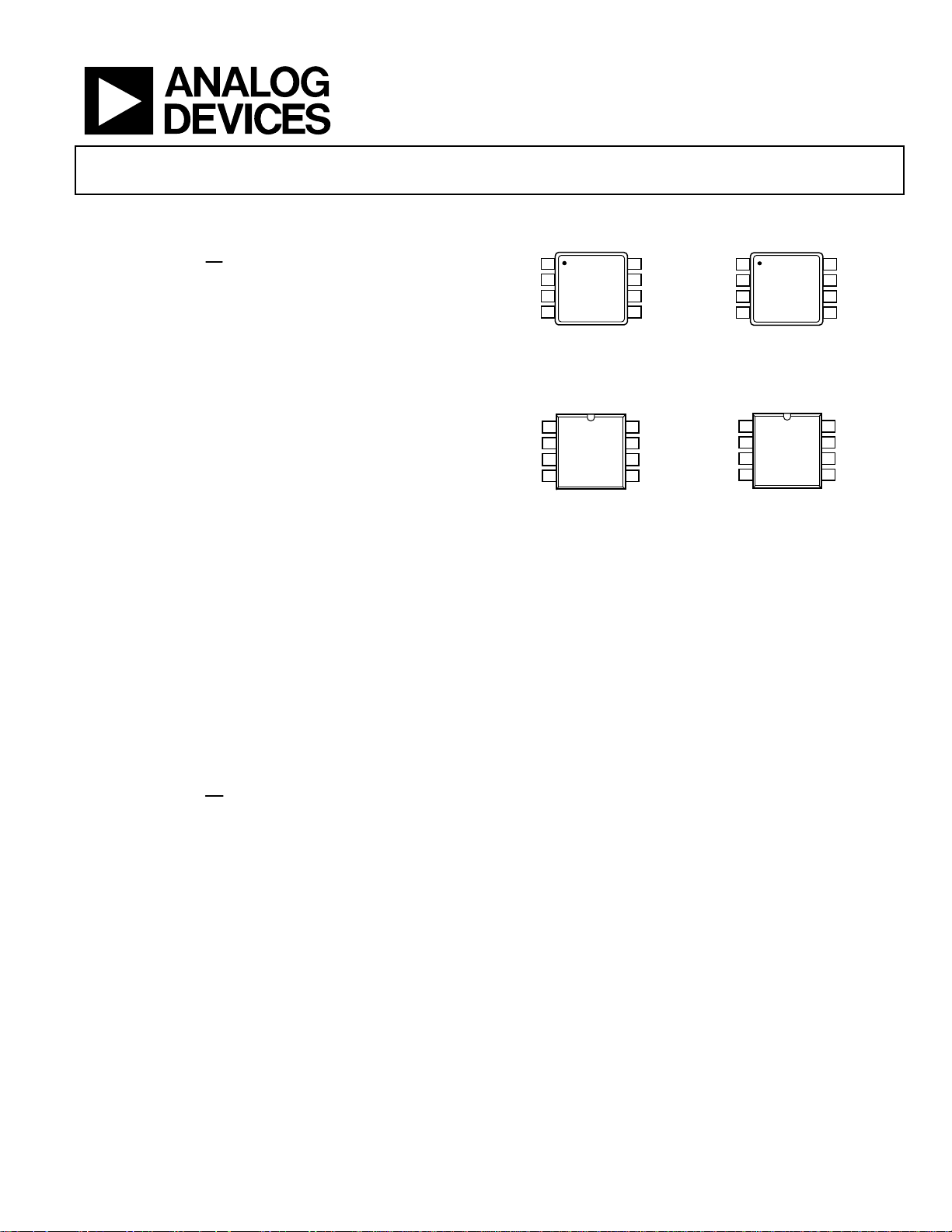
1
NC
AD8651
IN
2
TOP VIEW
IN
3
(Not to Scale)
4
V–
NC = NO CONNECT
Figure 1. 8-Lead MSOP (RM-8)
NC
1
AD8651
–IN
2
+IN
3
TOP VIEW
(Not to Scale)
V–
4
NC = NO CONNECT
Figure 3. 8-Lead SOIC (R-8)
PIN CONFIGURATIONS
8
7
6
5
8
7
6
5
NC
V+
OUT
NC
NC
V+
OUT
NC
AD8651/AD8652
OUT A
03301-0-001
03301-0-002
1
V–
AD8652
2
TOP VIEW
3
(Not to Scale)
4
–IN A
+IN A
Figure 2. 8-Lead MSOP (RM-8)
OUT A
1
V–
AD8652
2
3
TOP VIEW
(Not to Scale)
4
–IN A
+IN A
Figure 4. 8-Lead SOIC (R-8)
V+
8
OUT B
7
6
–IN B
5
+IN B
V+
8
OUT B
7
–IN B
6
+IN B
5
03301-B-003
03301-B-004
GENERAL DESCRIPTION
The AD8651 is a high precision, low noise, low distortion, railto-rail CMOS operational amplifier that runs from a singlesupply voltage of 2.7 V to 5 V.
The AD8651 is a rail-to-rail input and output amplifier with a
gain bandwidth of 50 MHz and a typical voltage offset of
100 µV across common mode from a 5 V supply. It also features
Hz
low noise—4.5 nV/√
The AD8651 can be used in communications applications, such
as cell phone transmission power control, fiber optic
networking, wireless networking, and video line drivers.
Rev. B
Information furnished by Analog Devices is believed to be accurate and reliable.
However, no responsibility is assumed by Analog Devices for its use, nor for any
infringements of patents or other rights of third parties that may result from its use.
Specifications subject to change without notice. No license is granted by implication
or otherwise under any patent or patent rights of Analog Devices. Trademarks and
registered trademarks are the property of their respective owners.
.
The AD8651 features the newest generation of DigiTrim®
in-package trimming. This new generation measures and
corrects the offset over the entire input common-mode range,
providing less distortion from V
variation than is typical of
OS
other rail-to-rail amplifiers. Offset voltage and CMRR are both
specified and guaranteed over the entire common-mode range
as well as over the extended industrial temperature range.
The AD8651 is offered in the 8-lead SOIC package and the
8-lead MSOP package. It is specified over the extended industrial temperature range (−40°C to +125°C).
One Technology Way, P.O. Box 9106, Norwood, MA 02062-9106, U.S.A.
Tel: 781.329.4700
Fax: 781.326.8703 © 2004 Analog Devices, Inc. All rights reserved.
www.analog.com

AD8651/AD8652
TABLE OF CONTENTS
Electrical Characteristics................................................................. 3
Layout, Grounding, and Bypassing considerations............... 15
Electrical Characteristics................................................................. 4
Absolute Maximum Ratings............................................................ 5
ESD Caution.................................................................................. 5
Typical Performance Characteristics............................................. 6
Applications..................................................................................... 14
Theory of Operation ..................................................................14
Rail-to-Rail Output Stage...................................................... 14
Rail-to-Rail Input Stage......................................................... 14
Input Protection ..................................................................... 15
Overdrive Recovery ............................................................... 15
REVISION HISTORY
9/04—Data Sheet Changed from Rev. A to Rev. B
Added AD8652 ....................................................................Universal
Change to General Description....................................................... 1
Changes to Electrical Characteristics ............................................. 3
Changes to Absolute Maximum Ratings........................................ 5
Change to Figure 23 .......................................................................... 9
Change to Figure 26 .......................................................................... 9
Change to Figure 36 ........................................................................ 11
Change to Figure 42 ........................................................................ 12
Change to Figure 49 ........................................................................ 13
Change to Figure 51 ........................................................................ 13
Inserted Figure 52............................................................................ 13
Change to Theory of Operation section....................................... 14
Change to Input Protection section ..............................................15
Changes to Ordering Guide........................................................... 20
Power Supply Bypassing........................................................ 15
Grounding............................................................................... 15
Leakage Currents.................................................................... 15
Input Capacitance .................................................................. 15
Output Capacitance ...............................................................16
Settling Time........................................................................... 16
THD Readings vs. Common-Mode Voltage ...................... 16
Driving a 16-Bit ADC............................................................ 17
Outline Dimensions .......................................................................18
Ordering Guide .......................................................................... 18
6/04—Changed from REV. 0 to REV. A
Change to Figure 18 .............................................................................8
Change to Figure 21 .............................................................................9
Change to Figure 29 .............................................................................10
Change to Figure 30 .............................................................................10
Change to Figure 43 .............................................................................12
Change to Figure 44 .............................................................................12
Change to Figure 47 .............................................................................13
Change to Figure 57 .............................................................................17
10/03 Revision 0: Initial Version
Rev. B | Page 2 of 20

AD8651/AD8652
ELECTRICAL CHARACTERISTICS
Table 1. V+ = 2.7 V, V– = 0 V, VCM = V+/2, TA = 25°C, unless otherwise specified
Parameter Symbol Conditions Min Typ Max Unit
INPUT CHARACTERISTICS
Offset Voltage V
OS
AD8651 0 ≤ VCM ≤ 2.7 V 100 350 μV
–40°C ≤ TA ≤ +85°C, 0 ≤ VCM ≤ 2.7 V 1.4 mV
–40°C ≤ TA ≤ +125°C, 0 ≤ VCM ≤ 2.7 V 1.6 mV
AD8652 0 ≤ VCM ≤ 2.7 V 90 300 μV
–40°C ≤ TA ≤ +125°C, 0 ≤ VCM ≤ 2.7 V 0.4 1.3 mV
Offset Voltage Drift 4 μV/°C
Input Bias Current I
B
–40°C ≤ TA ≤ +125°C 600 pA
Input Offset Current I
OS
–40°C ≤ TA ≤ +85°C 30 pA
–40°C ≤ TA ≤ +125°C 600 pA
Input Voltage Range V
CM
Common-Mode Rejection Ratio CMRR
AD8651 V+ = 2.7 V, –0.1 V < VCM < +2.8 V 75 95 dB
–40°C ≤ TA ≤ +85°C, –0.1 V < VCM < +2.8 V 70 88 dB
–40°C ≤ TA ≤ +125°C, –0.1 V < VCM < +2.8 V 65 85 dB
AD8652 V+ = 2.7 V, –0.1 V < VCM < +2.8 V 77 95 dB
–40°C ≤ TA ≤ +125°C, –0.1 V < VCM < +2.8 V 73 90 dB
Large Signal Voltage Gain A
VO
R
R
OUTPUT CHARACTERISTICS
Output Voltage High V
Output Voltage Low V
Short Circuit Limit I
OH
OL
SC
Sinking 80 mA
Output Current I
O
POWER SUPPLY
Power Supply Rejection Ratio PSRR VS = 2.7 V to 5.5 V, VCM = 0 V 76 94 dB
–40°C ≤ TA ≤ +125°C 74 93 dB
Supply Current I
SY
AD8651 IO = 0 9 12 mA
–40°C ≤ TA ≤ +125°C 14.5 mA
AD8652 IO = 0 17.5 19.5 mA
–40°C ≤ TA ≤ +125°C 22.5 mA
INPUT CAPACITANCE C
IN
Differential 6 pF
Common-Mode 9 pF
DYNAMIC PERFORMANCE
Slew Rate SR G = 1, RL = 10 kΩ 41 V/μs
Gain Bandwidth Product GBP G = 1 50 MHz
Settling Time, 0.01% G = ±1, 2 V Step 0.2 μs
Overload Recovery Time VIN × G = 1.48 V
Total Harmonic Distortion + Noise THD + N G = 1, RL = 600 Ω, f = 1 kHz, VIN = 2 V p-p 0.0006 %
NOISE PERFORMANCE
Voltage Noise Density e
n
f = 100 kHz 4.5
Current Noise Density i
n
1 10 pA
1 10 pA
–0.1 +2.8 V
RL = 1 kΩ, 200 mV < VO < 2.5 V 100 115 dB
= 1 kΩ, 200 mV < VO < 2.5 V, TA = +85°C 100 114 dB
L
= 1 kΩ, 200 mV < VO < 2.5 V, TA = +125°C 95 108 dB
L
IL = 250 μA, –40°C ≤ TA ≤ +125°C 2.67 V
IL = 250 μA, –40°C ≤ TA ≤ +125°C 30 mV
Sourcing 80 mA
+40 mA
+
f = 10 kHz 5
f = 10 kHz 4
0.1 μs
Hz
nV/√
Hz
nV/√
Hz
fA/√
Rev. B | Page 3 of 20

AD8651/AD8652
ELECTRICAL CHARACTERISTICS
Table 2. V+ = 5 V, V– = 0 V, VCM = V+/2, TA = 25°C, unless otherwise specified
Parameter Symbol Conditions Min Typ Max Unit
INPUT CHARACTERISTICS
Offset Voltage V
OS
AD8651 0 ≤ VCM ≤ 5 V 100 350 μV
–40°C ≤ TA ≤ +85°C, 0 ≤ VCM ≤ 5 V 1.4 mV
–40°C ≤ TA ≤ +125°C, 0 ≤ VCM ≤ 5 V 1.7 mV
AD8652 0 ≤ VCM ≤ 5 V 90 300 μV
–40°C ≤ TA ≤ +125°C, 0 ≤ VCM ≤ 5 V 0.4 1.4 mV
Offset Voltage Drift 4 μV/°C
Input Bias Current I
B
–40°C ≤ TA ≤ +85°C 30 pA
–40°C ≤ TA ≤ +125°C 600 pA
Input Offset Current I
OS
–40°C ≤ TA ≤ +85°C 30 pA
–40°C ≤ TA ≤ +125°C 600 pA
Input Voltage Range V
CM
Common-Mode Rejection Ratio CMRR
AD8651 0.1 V < VCM < 5.1 V 80 95 dB
–40°C ≤ TA ≤ +85°C, 0.1 V < VCM < 5.1 V 75 94 dB
–40°C ≤ TA ≤ +125°C, 0.1 V < VCM < 5.1 V 70 90 dB
AD8652 0.1 V < VCM < 5.1 V 84 100 dB
–40°C ≤ TA ≤ +125°C, 0.1 V < VCM < 5.1 V 76 95 dB
Large Signal Voltage Gain A
VO
R
R
OUTPUT CHARACTERISTICS
Output Voltage High V
Output Voltage Low V
Short Circuit Limit I
OH
OL
SC
Sinking 80 mA
Output Current I
O
POWER SUPPLY
Power Supply Rejection Ratio PSRR VS = 2.7 V to 5.5 V, V
–40°C ≤ TA ≤ +125°C 74 93 dB
Supply Current I
SY
AD8651 IO = 0 9.5 14.0 mA
–40°C ≤ TA ≤ +125°C 15 mA
AD8652 IO = 0 17.5 20.0 mA
–40°C ≤ TA ≤ +125°C 23.5 mA
INPUT CAPACITANCE C
IN
Differential 6 pF
Common-Mode 9 pF
DYNAMIC PERFORMANCE
Slew Rate SR G = 1, RL = 10 kΩ 41 V/µs
Gain Bandwidth Product GBP G = 1 50 MHz
Settling Time, 0.01% G = ±1, 2 V Step 0.2 μs
Overload Recovery Time VIN × G = 1.2 V
Total Harmonic Distortion + Noise THD + N G = 1, RL = 600 Ω, f = 1 kHz, VIN = 2 V p-p 0.0006 %
NOISE PERFORMANCE
Voltage Noise Density e
n
f = 100 kHz 4.5
Current Noise Density I
n
1 10 pA
1 10 pA
–0.1 +5.1 V
RL = 1 kΩ, 200 mV < VO < 4.8 V 100 115 dB
= 1 kΩ, 200 mV < VO < 4.8 V, TA = +85°C 98 114 dB
L
= 1 kΩ, 200 mV < VO < 4.8 V, TA = +125°C 95 111 dB
L
IL = 250 µA, –40°C ≤ TA ≤ +125°C 4.97 V
IL = 250 µA, –40°C ≤ TA ≤ +125°C 30 mV
Sourcing 80 mA
+40 mA
= 0 V 76 94 dB
CM
+
f = 10 kHz 5
f = 10 kHz 4
0.1 μs
Hz
nV/√
Hz
nV/√
Hz
fA/√
Rev. B | Page 4 of 20
AD8651/AD8652
ABSOLUTE MAXIMUM RATINGS
Absolute maximum ratings apply at 25°C, unless otherwise noted.
Table 3.
Parameter Rating
Supply Voltage 6.0 V
Input Voltage GND to VS + 0.3 V
Differential Input Voltage ±6.0 V
Output Short-Circuit Duration to GND Indefinite
Electrostatic Discharge (HBM) 4000 V
Storage Temperature Range
RM, R Package −65°C to +150°C
Operating Temperature Range −40°C to +125°C
Junction Temperature Range
RM, R Package −65°C to +150°C
Lead Temperature (Soldering, 10 s) 300°C
Stresses above those listed under Absolute Maximum Ratings
may cause permanent damage to the device. This is a stress
rating only; functional operation of the device at these or any
other conditions above those indicated in the operational
section of this specification is not implied. Exposure to absolute
maximum rating conditions for extended periods may affect
device reliability.
Table 4.
Package Type θ
8-Lead MSOP (RM) 210 45 °C/W
8-Lead SOIC (R) 158 43 °C/W
1
JA
θ
JC
Unit
1
θJA is specified for the worst-case conditions, i.e., θJA is specified for device
soldered in circuit board for surface-mount packages.
ESD CAUTION
ESD (electrostatic discharge) sensitive device. Electrostatic charges as high as 4000 V readily accumulate on
the human body and test equipment and can discharge without detection. Although this product features
proprietary ESD protection circuitry, permanent damage may occur on devices subjected to high energy
electrostatic discharges. Therefore, proper ESD precautions are recommended to avoid performance
degradation or loss of functionality.
Rev. B | Page 5 of 20
AD8651/AD8652
TYPICAL PERFORMANCE CHARACTERISTICS
60
50
VS = ±2.5V
V
= 0V
CM
100
VS = 5V
80
(µV)
V
NUMBER OF AMPLIFIERS
OS
300
200
100
–100
–200
40
30
20
10
0
–200
–160
–120
–80
–40
VOS (µV)
0
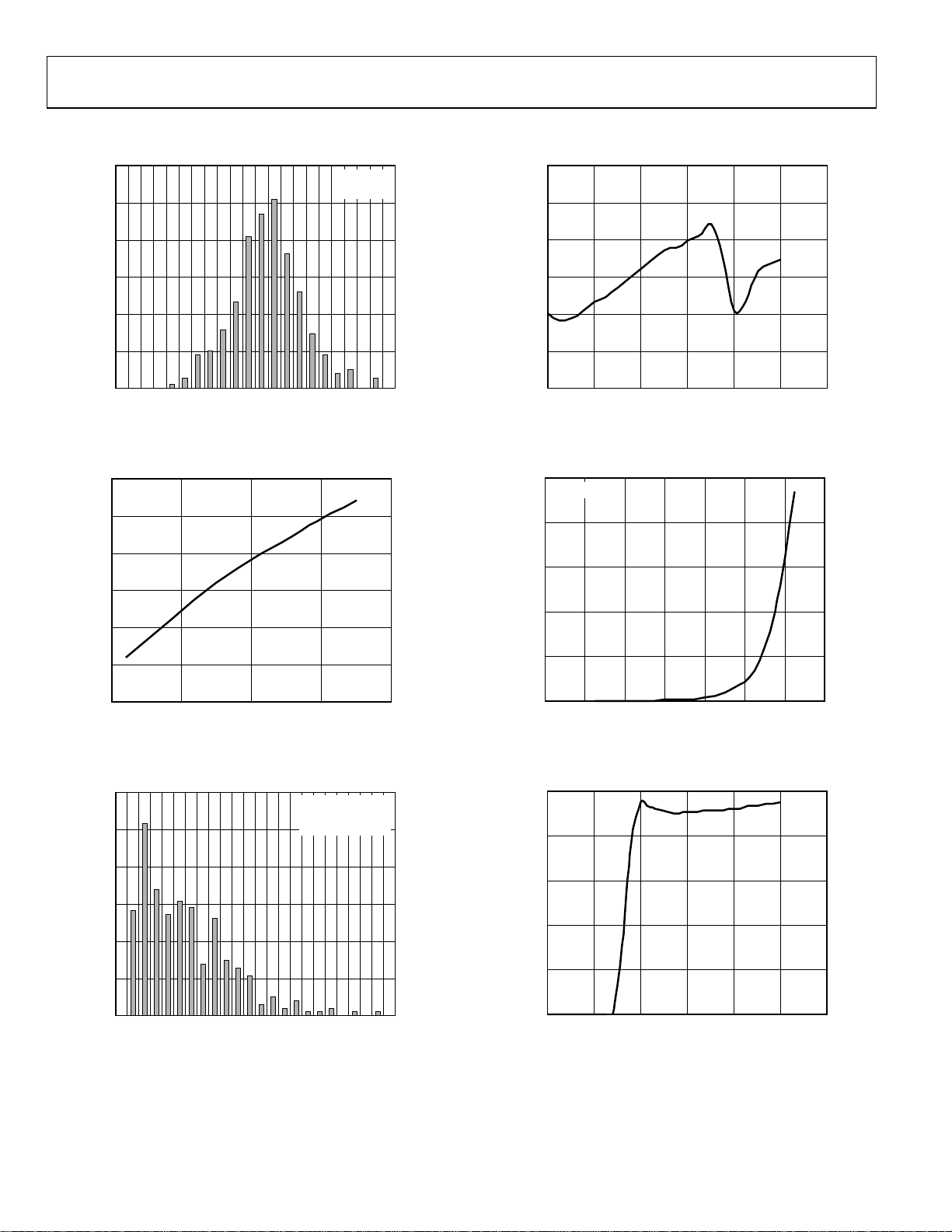
Figure 5. Input Offset Voltage Distribution
VS = ±2.5V
= 0V
V
CM
0
60
40
(µV)
OS
V
20
0
–20
40
80
120
160
200
03301-B-005
0123456
COMMON-MODE VOLTAGE (V)
03301-B-008
Figure 8. Input Offset Voltage vs. Common-Mode Voltage
500
VS = ±2.5V
400
300
200
INPUT BAIS CURRENT (pA)
100
–300
–50 0 50 100 150
TEMPERATURE (°C)
Figure 6. Input Offset Voltage vs. Temperature
60
50
40
30
20
NUMBER OF AMPLIFIERS
10
0
01234567891011
TCVOS (µV/°C)
Figure 7. TCV
Distribution
OS
VS = ±2.5V
V
= 0V
CM
T: –40°C TO 125°C
0
03301-B-006
0 40 140120100806020
TEMPERATURE (°C)
03301-B-009
Figure 9. Input Bias Current vs. Temperature
10
8
6
4
SUPPLY CURRENT (mA)
2
0
03301-B-007
02 5431 6
SUPPLY VOLTAGE (V)
03301-B-010
Figure 10. Supply Current vs. Supply Voltage
Rev. B | Page 6 of 20

AD8651/AD8652
12
VS = ±2.5V
11
2.50
2.00
VS = 5V
I
= 250µA
L
10
9
8
SUPPLY CURRENT (mA)
7
6
–50 0 50 100 150
TEMPERATURE (°C)
Figure 11. Supply Current vs. Temperature
500
400
300
(mV)
– V
V
OUT
SY
200
100
V
OH
V
OL
VS = ±2.5V
1.50
1.00
OUTPUT SWING LOW (mV)
0.50
0
03301-B-011
–50 0 50 100 150
TEMPERATURE (°C)
03301-B-014
Figure 14. Output Voltage Swing Low vs. Temperature
100
80
60
40
CMRR (dB)
20
VS = ±2.5V
0
0 20 40 60 10080
CURRENT LOAD (mA)
Figure 12. Output Voltage to Supply Rail vs. Load Current
4.997
4.996
4.995
4.994
4.993
4.992
OUTPUT SWING HIGH (V)
4.991
4.990
–50 0 50 100 150
TEMPERATURE (°C)
VS = 5V
I
L
Figure 13. Output Voltage Swing High vs. Temperature
= 250µA
0
03301-B-012
10 1k 10M1M100k10k100
FREQUENCY (Hz)
03301-B-015
Figure 15. CMRR vs. Fre quency
110
105
100
CMRR (dB)
95
90
03301-B-013
–50 0 50 100 150
TEMPERATURE (°C)
VS = ±2.5V
03301-B-016
Figure 16. CMRR vs. Temperature
Rev. B | Page 7 of 20

AD8651/AD8652
100
97
94
100
VS = ±2.5V
91
CMRR (dB)
88
85
82
–50 0 50 100 150
TEMPERATURE (°C)
Figure 17. CMRR vs. Temperature
100
80
60
40
PSRR (dB)
20
0
1 10 100 1k 10k 100k 1M 10M 100M
+PSRR
–PSRR
FREQUENCY (Hz)
VS = ±2.5V
Figure 18. PSRR v s. Frequency
10
VOLTAGE NOISE DENSITY (nV/√Hz)
1
03301-B-017
10 1k 100k10k100
FREQUENCY (Hz)
03301-B-020
Figure 20. Voltage Noise Density vs. Frequency
80
60
40
20
CURRENT NOISE DENSITY (fA/√Hz)
0
03301-B-018
100 1k 100k10k
FREQUENCY (Hz)
VS = ±2.5V
03301-B-021
Figure 21. Current Noise Density vs. Frequency
100
95
90
PSRR (dB)
85
80
–50 0 50 100 150
TEMPERATURE (°C)
Figure 19. PSRR vs. Temperature
VS = ±2.5V
03301-B-019
Rev. B | Page 8 of 20
VS = ±2.5V
V
= 6.4V
IN
V
IN
V
OUT
0
VOLTAGE (1V/DIV)
TIME (200µs/DIV)
03301-B-022
Figure 22. No Phase Reversal

AD8651/AD8652
140
120
100
VS = ±2.5V
0
–45
60
40
G = 100
VS = ±2.5V
R
= 1MΩ
L
= 47pF
C
L
80
60
40
OPEN-LOOP GAIN (dB)
20
0
–20
10 100 1k 10k 100k 1M 10M 100M
FREQUENCY (Hz)
Figure 23. Open-Loop Gain and Phase vs. Frequency
117
116
115
(dB)
VO
A
114
113
VS = ±2.5V
= 1k
Ω
R
L
–90
–135
–180
PHASE (Degrees)
03301-B-023
20
G = 10
0
G = 1
CLOSED-LOOP GAIN (dB)
–20
–40
5k
50k 5M500k 50M 300M
FREQUENCY (Hz)
03301-B-026
Figure 26. Closed-Loop Gain vs. Frequency
6
5
4
3
2
MAXIMUM OUTPUT SWING (V)
1
VS = 5V
VS = 2.7V
112
–50 0 50 100 150
TEMPERATURE (°C)
Figure 24. Open-Loop Gain vs. Temperature
140
130
2.5mA
120
110
100
90
OPEN-LOOP GAIN (dB)
80
70
60
0 50 100 150 250200
OUTPUT VOLTAGE SWING FROM THE RAILS (mV)
4.2mA
IL = 250µA
Figure 25. Open-Loop Gain vs. Output Voltage Swing
VS = ±2.5V
0
03301-B-024
100k 100M10M1M
FREQUENCY (Hz)
03301-B-027
Figure 27. Maximum Output Swing vs. Frequency
VS = ±2.5V
C
= 47pF
L
A
= 1
V
VOLTAGE (1V/DIV)
03301-B-025
TIME (100µs/DIV)
03301-B-028
Figure 28. Large Signal Response
Rev. B | Page 9 of 20

AD8651/AD8652
2
VS = ±2.5V
V
= 200mV
IN
A
= 1
V
–2.5V
VS = ±2.5V
V
= 200mV
IN
0V
GAIN = –15
OUTPUT
VOLTAGE (100mV/DIV)
TIME (10µs/DIV)
Figure 29. Small Signal Response
30
VS = ±2.5V
V
= 200mV
IN
A
= 1
V
25
SMALL SIGNAL OVERSHOOT (%)
20
15
10
5
0
020 6050403010
CAPACITANCE (pF)
–OS
Figure 30. Small Signal Overshoot vs. Load Capacitance
+OS
03301-B-029
70
03301-B-030
00mV
0V
40
VS = ±2.5V
30
20
10
OUTPUT IMPEDANCE (Ω)
0
10 1000 10000010000100
INPUT
TIME (200ns/DIV)
Figure 32. Positive Overload Recovery Time
GAIN = 10
GAIN = 1
GAIN = 100
FREQUENCY (Hz)
Figure 33. Output Impedance vs. Frequency
03301-B-032
03301-B-033
2.5V
–200mV
0V
0V
TIME (200ns/DIV)
Figure 31. Negative Overload Recovery Time
VS = ±2.5V
= 200mV
V
IN
GAIN = –15
03301-B-031
Rev. B | Page 10 of 20
NUMBER OF AMPLIFIERS
60
50
40
30
20
10
0
–200
–160
–120
–80
–40
VOS (µV)
0
Figure 34. Input Offset Voltage Distribution
VS = ±1.35V
V
= 0V
CM
40
80
120
160
200
03301-B-034

AD8651/AD8652
300
200
VS = ±1.35V
= 0V
V
CM
500
400
VS = ±1.35V
100
V)
µ
0
(
OS
V
–100
–200
–300
–50 0 50 100 150
TEMPERATURE (°C)
Figure 35. Input Offset Voltage vs. Temperature
80
60
40
20
0
INPUT OFFSET VOLTAGE (µV)
VS = 2.7V
300
(mV)
OUT
– V
200
SY
V
100
0
03301-B-035
0 20 40 60 10080
V
OH
CURRENT LOAD (mA)
V
OL
03301-B-038
Figure 38. Output Voltage to Supply Rail vs. Load Current
2.697
2.696
2.695
2.694
2.693
2.692
OUTPUT SWING HIGH (V)
2.691
VS = 2.7V
I
= 250µA
L
–20
0123
INPUT COMMON-MODE VOLTAGE (V)
Figure 36. Input Offset Voltage vs. Common-Mode Voltage
11
VS = ±1.35V
10
9
8
SUPPLY CURRENT (mA)
7
6
–50 0 50 100 150
TEMPERATURE (°C)
Figure 37. Supply Current vs. Temperature
2.690
03301-B-036
–50 0 50 100 150
TEMPERATURE (°C)
03301-B-039
Figure 39. Output Voltage Swing High vs. Temperature
3.00
2.50
2.00
1.50
1.00
OUTPUT SWING LOW (mV)
0.50
0
03301-B-037
–50 0 50 100 150
TEMPERATURE (°C)
VS = 2.7V
= 250µA
I
L
03301-B-040
Figure 40. Output Voltage Swing Low vs. Temperature
Rev. B | Page 11 of 20

AD8651/AD8652
VS = ±1.35V
A
= 1
V
30
25
20
VS = ±1.35V
V
= 200mV
IN
15
VOLTAGE (1V/DIV)
TIME (200µs/DIV)
03301-B-041
Figure 41. No Phase Reversal
VS = ±1.35V
C
= 47pF
L
A
= 1
V
VOLTAGE (500mV/DIV)
TIME (100µs/DIV)
03301-B-042
Figure 42. Large Signal Response
10
5
SMALL SIGNAL OVERSHOOT (%)
0
020 6050403010
CAPACITANCE (pF)
Figure 44. Small Signal Overshoot vs. Load Capacitance
1.35V
0V
0V
–200mV
Figure 45. Negative Overload Recovery Time
–OS
TIME (200ns/DIV)
+OS
VS = ±1.35V
V
= 200mV
IN
GAIN = –10
70
03301-B-044
03301-B-045
VS = ±1.35V
V
= 200mV
IN
C
= 47pF
L
A
= 1
V
VOLTAGE (100mV/DIV)
TIME (10µs/DIV)
03301-B-043
Figure 43. Small Signal Response
0V
–1.35V
200mV
0V
TIME (200ns/DIV)
Figure 46. Positive Overload Recovery Time
VS = ±1.35V
V
= 200mV
IN
GAIN = –10
03301-B-046
Rev. B | Page 12 of 20

AD8651/AD8652
100
VS = ±1.35V
80
120
118
VS = ±1.35V
R
= 1k
Ω
L
60
40
CMRR (dB)
20
0
10 1k 10M1M100k10k100
100
80
60
40
PSRR (dB)
20
FREQUENCY (Hz)
Figure 47. CMRR vs. Fre quency
+PSRR
–PSRR
VS = ±1.35V
116
114
(dB)
VO
A
112
110
108
03301-B-047
–50 0 50 100 150
TEMPERATURE (°C)
03301-B-051
Figure 50. Open-Loop Gain vs. Temperature
60
40
G = 100
20
G = 10
0
G = 1
CLOSED-LOOP GAIN (dB)
–20
VS = ±1.35V
RL = 1M
Ω
CL = 47pF
0
1 10 100 1k 10k 100k 1M 10M
FREQUENCY (Hz)
Figure 48. PSRR v s. Frequency
140
120
100
80
60
40
OPEN-LOOP GAIN (dB)
20
0
–20
10 100 1k 10k 100k 1M 10M 100M
FREQUENCY (Hz)
Figure 49. Open-Loop Gain and Phase vs. Frequency
VS = ±1.35V
0
–45
–90
–135
–180
03301-B-048
PHASE (Degrees)
03301-B-050
–40
5k
50k 5M500k 50M 300M
Figure 51. Closed-Loop Gain vs. Frequency
0
–20
V
–40
–60
–80
–100
CHANNEL SEPARATION (dB)
–120
–140
28mV p-p
IN
Figure 52. Channel Separation
FREQUENCY (Hz)
+2.5V
V+
V–
–2.5V
FREQUENCY (Hz)
03301-B-052
R1
10kΩ
V–
V
OUT
V+
R2
100Ω
VS = ±2.5V
10M100 1k 10k 100k 1M
03301-B-062
Rev. B | Page 13 of 20

AD8651/AD8652
APPLICATIONS
THEORY OF OPERATION
The AD8651 amplifier is a voltage feedback, rail-to-rail input
and output precision CMOS amplifier that operates from 2.7 V
to 5.0 V of power supply voltage. This amplifier uses Analog
Devices’ DigiTrim technology to achieve a higher degree of
precision than is available from most CMOS amplifiers.
DigiTrim technology, used in a number of ADI amplifiers, is a
method of trimming the offset voltage of the amplifier after it
has been assembled. The advantage of post-package trimming is
that it corrects any offset voltages caused by the mechanical
stresses of assembly.
The AD8651 is available in standard op amp pinout, making
DigiTrim completely transparent to the user. The input stage of
the amplifier is a true rail-to-rail architecture, allowing the
input common-mode voltage range of the op amp to extend to
both positive and negative supply rails. The open-loop gain of
the AD8651/AD8652 with a load of 1 kΩ is typically 115 dB.
The AD8651 can be used in any precision op amp application.
The amplifier does not exhibit phase reversal for commonmode voltages within the power supply. With voltage noise of
Hz
4.5 nV/√
the AD8651/AD8652 is a great choice for high resolution data
acquisition systems. Its low noise, sub-pA input bias current,
precision offset, and high speed make it a superb preamp
for fast photodiode applications. The speed and output
drive capability of the AD8651 also make it useful in
video applications.
Rail-to-Rail Output Stage
The voltage swing of the output stage is rail-to-rail and is
achieved by using an NMOS and PMOS transistor pair connected in a common source configuration. The maximum
and –105 dB distortion for 10 kHz, 2 V p-p signals,
600
output voltage swing is proportional to the output current, and
larger currents will limit how close the output voltage can get to
the proximity of the output voltage to the supply rail. This is a
characteristic of all rail-to-rail output amplifiers. With 40 mA of
output current, the output voltage can reach within 5 mV of the
positive and negative rails. At light loads of >100 kΩ, the output
swings within ~1 mV of the supplies.
Rail-to-Rail Input Stage
The input common-mode voltage range of the AD8651 extends
to both positive and negative supply voltages. This maximizes
the usable voltage range of the amplifier, an important feature
for single-supply and low voltage applications. This rail-to-rail
input range is achieved by using two input differential pairs, one
NMOS and one PMOS, placed in parallel. The NMOS pair is
active at the upper end of the common-mode voltage range,
and the PMOS pair is active at the lower end of the commonmode range.
The NMOS and PMOS input stages are separately trimmed
using DigiTrim to minimize the offset voltage in both differential pairs. Both NMOS and PMOS input differential pairs are
active in a 500 mV transition region when the input commonmode voltage is approximately 1.5 V below the positive supply
voltage. A special design technique improves the input offset
voltage in the transition region that traditionally exhibits a
slight V
variation. As a result, the common-mode rejection
OS
ratio is improved within this transition band. Compared to the
Burr Brown OPA350 amplifier, shown in Figure 53 (A), the
AD8651, shown in Figure 53 (B), exhibits much lower offset
voltage shift across the entire input common-mode range,
including the transition region.
600
400
200
V)
µ
0
(
OS
V
–200
–400
–600
0
(A) OPA350 VOS vs. VCM (B) AD8651 VOS vs. VCM
214356
COMMON-MODE VOLTAGE (V)
Figure 53. Input Offset Distribution over Common-Mode Voltage
400
200
0
(µV)
OS
V
–200
–400
–600
03301-B-053
0
214356
COMMON-MODE VOLTAGE (V)
03301-B-054
Rev. B | Page 14 of 20

AD8651/AD8652
Input Protection
As with any semiconductor device, if a condition could exist for
the input voltage to exceed the power supply, the device’s input
overvoltage characteristic must be considered. The inputs of the
AD8651 are protected with ESD diodes to either power supply.
Excess input voltage will energize internal PN junctions in the
AD8651, allowing current to flow from the input to the
supplies. This results in an input stage with picoamps of input
current that can withstand up to 4000 V ESD events (human
body model) with no degradation.
Excessive power dissipation through the protection devices will
destroy or degrade the performance of any amplifier. Differential voltages greater than 7 V will result in an input current of
approximately (|V
– VEE| – 0.7 V)/RI, where RI is the
CC
resistance in series with the inputs. For input voltages beyond
the positive supply, the input current will be approximately (V
– 0.7)/RI. For input voltages beyond the negative supply,
– V
CC
the input current will be about (V
– VEE + 0.7)/RI. If the inputs
I
I
of the amplifier sustain differential voltages greater than 7 V or
input voltages beyond the amplifier power supply, limit the
input current to 10 mA by using an appropriately sized input
resistor (R
), as shown in Figure 54.
I
(| VCC– VEE| – 0.7V)
>
R
I
FOR LARGE | V
30mA
– VEE |
CC
–VI+
Figure 54. Input Protection Method
(V
– VEE– 0.7V)
I
R
>
I
30mA
– VEE+ 0.7V)
(V
I
R
>
I
+
AD8651
–
R
I
30mA
FOR V
BEYOND
I
SUPPLY VOLTAGES
+V
O
03301-B-055
Overdrive Recovery
Overdrive recovery is defined as the time it takes for the output
of an amplifier to come off the supply rail after an overload
signal is initiated. This is usually tested by placing the amplifier
in a closed-loop gain of 15 with an input square wave of
200 mV p-p while the amplifier is powered from either 5 V or
3 V. The AD8651 has excellent recovery time from overload
conditions (see Figure 31 and Figure 32). The output recovers
from the positive supply rail within 200 ns at all supply voltages.
Recovery from the negative rail is within 100 ns at 5 V supply.
LAYOUT, GROUNDING, AND BYPASSING CONSIDERATIONS
Power Supply Bypassing
Power supply pins can act as inputs for noise, so care must be
taken that a noise-free, stable dc voltage is applied. The purpose
of bypass capacitors is to create low impedances from the supply
to ground at all frequencies, thereby shunting or filtering most
of the noise. Bypassing schemes are designed to minimize the
supply impedance at all frequencies with a parallel combination
of capacitors of 0.1 µF and 4.7 µF. Chip capacitors of 0.1 µF
(X7R or NPO) are critical and should be as close as possible to
the amplifier package. The 4.7 µF tantalum capacitor is less
critical for high frequency bypassing, and, in most cases, only
one is needed per board at the supply inputs.
Grounding
A ground plane layer is important for densely packed PC
boards to spread the current-minimizing parasitic inductances.
However, an understanding of where the current flows in a
circuit is critical to implementing effective high speed circuit
design. The length of the current path is directly proportional to
the magnitude of parasitic inductances and, therefore, the high
frequency impedance of the path. High speed currents in an
inductive ground return will create an unwanted voltage noise.
The length of the high frequency bypass capacitor leads is
critical. A parasitic inductance in the bypass grounding will
work against the low impedance created by the bypass capacitor.
Place the ground leads of the bypass capacitors at the same
physical location. Because load currents also flow from the
supplies, the ground for the load impedance should be at the
same physical location as the bypass capacitor grounds. For the
larger value capacitors, intended to be effective at lower frequencies, the current return path distance is less critical.
Leakage Currents
Poor PC board layout, contaminants, and the board insulator
material can create leakage currents that are much larger than
the input bias current of the AD8651/AD8652. Any voltage
differential between the inputs and nearby traces will set up
leakage currents through the PC board insulator, for example,
1 V/100 G = 10 pA. Similarly, any contaminants on the board
can create significant leakage (skin oils are a common problem).
To significantly reduce leakages, put a guard ring (shield)
around the inputs and input leads that are driven to the same
voltage potential as the inputs. This ensures that there is no
voltage potential between the inputs and the surrounding area
to set up any leakage currents. To be effective, the guard ring
must be driven by a relatively low impedance source and should
completely surround the input leads on all sides, above and
below, using a multilayer board.
Another effect that can cause leakage currents is the charge
absorption of the insulator material itself. Minimizing the
amount of material between the input leads and the guard
ring will help to reduce the absorption. Also, low absorption
materials, such as Teflon® or ceramic, may be necessary in
some instances.
Input Capacitance
Along with bypassing and ground, high speed amplifiers can be
sensitive to parasitic capacitance between the inputs and
ground. A few picofarads of capacitance will reduce the input
impedance at high frequencies, which in turn increases the
amplifier’s gain, causing peaking in the frequency response or
Rev. B | Page 15 of 20

AD8651/AD8652
oscillations. With the AD8651, additional input damping is
required for stability with capacitive loads greater than 47 pF
with direct input to output feedback (see the next section).
Output Capacitance
When using high speed amplifiers, it is important to consider
the effects of the capacitive loading on the amplifier’s stability.
Capacitive loading interacts with the output impedance of the
amplifier, causing reduction of the BW as well as peaking and
ringing of the frequency response. To reduce the effects of the
capacitive loading and allow higher capacitive loads, there are
two commonly used methods:
1) As shown in Figure 55, place a small value resistor (R
series with the output to isolate the load capacitor from the
amplifier’s output. Heavy capacitive loads can reduce the phase
margin of an amplifier and cause the amplifier response to peak
or become unstable. The AD8651 is able to drive up to 47 pF in
a unity gain buffer configuration without oscillation or external
compensation. However, if an application will require a higher
capacitive load drive when the AD8651 is in unity gain, then
the use of external isolation networks can be used. The effect
produced by this resistor is to isolate the op amp output from
the capacitive load. The required amount of series resistance has
been tabulated in Table 5 for different capacitive load. While
this technique will improve the overall capacitive load drive for
the amplifier, its biggest drawback is that it reduces the output
swing of the overall circuit.
V
CC
U1
3
V
+
IN
AD8651
2
–
V
+
V–
0
R
S
V
OUT
RLCL
0
0
Figure 55. Driving Large Capacitive Loads
Table 5. Optimum Values for Driving Large Capacitive Loads
CL R
S
100 pF 50 Ω
500 pF 35 Ω
1.0 nF 25 Ω
2) Another way to stabilize an op amp driving a large capacitive
load is to use a snubber network, as shown in Figure 56.
Because there is not any isolation resistor in the signal path, this
method has the significant advantage of not reducing the output
swing. The exact values of R
In Figure 56, an optimum R
and CS are derived experimentally.
S
and CS combination for a
S
capacitive load drive ranging from 50 pF to 1 nF was chosen.
For this, R
= 3 Ω and CS = 10 nF were chosen.
S
) in
S
03301-B-056
V
+
+
V
200mV
+
AD8651
V–
–
V–
R
S
CL
C
S
V
OUT
RL
03301-B-057
Figure 56. Snubber Network
Settling Time
The settling time of an amplifier is defined as the time it takes
for the output to respond to a step change of input and enter
and remain within a defined error band, as measured relative to
the 50% point of the input pulse. This parameter is especially
important in measurements and control circuits where amplifiers are used to buffer A/D inputs or DAC outputs. The design of
the AD8651 combines a high slew rate and a wide gain bandwidth product to produce an amplifier with very fast settling
time. The AD8651 is configured in the noninverting gain of 1
with a 2 V p-p step applied to its input. The AD8651 has a
settling time of about 130 ns to 0.01% (2 mV). The output is
monitored with a 10×, 10 M, 11.2 pF scope probe.
THD Readings vs. Common-Mode Voltage
Total harmonic distortion of the AD8651 is well below 0.0004%
with any load down to 600 Ω. The distortion is a function of the
circuit configuration, the voltage applied, and the layout, in
addition to other factors. The AD8651 outperforms its
competitor for distortion, especially at frequencies below
20 kHz, as shown in Figure 57.
0.1
0.05
0.02
0.01
0.005
0.002
0.001
THD + NOISE (%)
0.0005
0.0002
0.0001
20 50 100 500 20k5k2k1k
OPA350
FREQUENCY (Hz)
Figure 57. Total Harmonic Distortion
3.5V
–
AD8651
+
–1.5V
V
IN
2V p-p
Figure 58. THD + N Test Circuit
AD8651
600Ω
VSY = +3.5V/–1.5V
V
= 2.0V p-p
OUT
V
OUT
47pF
03301-B-059
03301-B-058
Rev. B | Page 16 of 20

AD8651/AD8652
Driving a 16-Bit ADC
The AD8651 is an excellent choice for driving high speed, high
precision ADCs. The driver amplifier for this type of
application needs to have low THD + N as well as quick settling
time. Figure 60 shows a complete single-supply data acquisition
solution. The AD8651 drives the AD7685, a 250 kSPS, 16-bit
data converter.
1
The AD8651 is configured in an inverting gain of 1 with a 5 V
single supply. Input of 45 kHz is applied, and the ADC samples
at 250 kSPS. The results of this solution are listed in Table 6.
The advantage of this circuit is that the amplifier and ADC can
be powered with the same power supply. For the case of a
noninverting gain of 1, the input common-mode voltage
encompasses both supplies.
0
–20
–40
–60
–80
–100
–120
AMPLITUDE (dB of Full Scale)
–140
f
= 250kSPS
SAMPLE
fIN = 45kHz
INPUT RANGE = 0 TO 5V
5V
1µF
10kΩ
10kΩ
= 45kHz
f
IN
V
0V – 5V
1kΩ
IN
3
+
AD8651
2
–
V
V–
1kΩ
U1
2.7nF
IN
V
CC
AD7685
+
33Ω
Figure 60. AD8651 Driving a 16-Bit ADC
Table 6. Data Acquisition Solution of Figure 60
Parameter Reading (dB)
THD + N 105.2
SFDR 106.6
2nd Harmonics 107.7
3rd Harmonics 113.6
1
For more information about the AD7685 data converter, go to
http://www.analog.com/Analog_Root/productPage/productHome/0%2C21
21%2CAD7685%2C00.html
03301-B-061
–160
10 20 30 40 50 60 70 80 90 100 110 120
0
FREQUENCY (kHz)
Figure 59. Frequency Response of AD8651 Driving a 16-Bit ADC
03301-B-060
Rev. B | Page 17 of 20

OUTLINE DIMENSIONS
3.00
BSC
85
3.00
BSC
PIN 1
0.65 BSC
0.15
0.00
0.38
0.22
COPLANARITY
0.10
COMPLIANT TO JEDEC STANDARDS MO-187AA
BSC
4
SEATING
PLANE
4.90
1.10 MAX
0.23
0.08
8°
0°
0.80
0.60
0.40
Figure 61. 8-Lead Mini Small Outline Package [MSOP]
(RM-8)
Dimensions shown in millimeters
5.00 (0.1968)
4.80 (0.1890)
4.00 (0.1574)
3.80 (0.1497)
0.25 (0.0098)
0.10 (0.0040)
COPLANARITY
0.10
CONTROLLING DIMENSIONS ARE IN MILLIMETERS; INCH DIMENSIONS
(IN PARENTHESES) ARE ROUNDED-OFF MILLIMETER EQUIVALENTS FOR
REFERENCE ONLY AND ARE NOT APPROPRIATE FOR USE IN DESIGN
85
1.27 (0.0500)
SEATING
PLANE
COMPLIANT TO JEDEC STANDARDS MS-012AA
BSC
6.20 (0.2440)
5.80 (0.2284)
41
1.75 (0.0688)
1.35 (0.0532)
0.51 (0.0201)
0.31 (0.0122)
0.25 (0.0098)
0.17 (0.0067)
0.50 (0.0196)
0.25 (0.0099)
8°
1.27 (0.0500)
0°
0.40 (0.0157)
Figure 62. 8-Lead Standard Small Outline Package [SOIC]
(R-8)
Dimensions shown in millimeters and (inches)
× 45°
ORDERING GUIDE
Model Temperature Range Package Description Package Option Branding
AD8651ARM-REEL –40°C to +125°C 8-Lead MSOP RM-8 BEA
AD8651ARM-R2 –40°C to +125°C 8-Lead MSOP RM-8 BEA
AD8651AR –40°C to +125°C 8-Lead SOIC R-8
AD8651AR-REEL –40°C to +125°C 8-Lead SOIC R-8
AD8651AR-REEL7 –40°C to +125°C 8-Lead SOIC R-8
AD8652ARMZ-R2
AD8652ARMZ-REEL* –40°C to +125°C 8-Lead MSOP RM-8 A05
AD8652ARZ* –40°C to +125°C 8-Lead SOIC R-8
AD8652ARZ-REEL* –40°C to +125°C 8-Lead SOIC R-8
AD8652ARZ-REEL7* –40°C to +125°C 8-Lead SOIC R-8
*
Z = Pb-free part.
*
–40°C to +125°C 8-Lead MSOP RM-8 A05
Rev. B | Page 18 of 20

AD8651/AD8652
NOTES
Rev. B | Page 19 of 20

NOTES
© 2004 Analog Devices, Inc. All rights reserved. Trademarks and
registered trademarks are the property of their respective owners.
C03301-0-9/04(B)
Rev. B | Page 20 of 20
 Loading...