


Dual, High Voltage
–
–
www.BDTIC.com/ADI
FEATURES
±4000 V HBM ESD
High common-mode voltage range
−2 V to +65 V operating
−3 V to +68 V survival
Buffered output voltage
Wide operating temperature range
10-lead MSOP: −40°C to +125°C
Excellent ac and dc performance
3 μV/°C typical offset drift
−10 ppm/°C typical gain drift
120 dB typical CMRR at dc
APPLICATIONS
High-side current sensing
Motor controls
Transmission controls
Diesel injection controls
Engine management
Suspension controls
Vehicle dynamic controls
DC-to-DC converters
Current Shunt Monitor
AD8213
FUNCTIONAL BLOCK DIAGRAM
OUT2
IN2 +IN2
PROPRIETARY
OFFSET
CIRCUITRY
G = +20
A2
CF2
Figure 1.
A1
PROPRIETARY
OFFSET
CIRCUITRY
CF1GND
IN1+IN1
G = +20
AD8213
V+
OUT1
06639-001
GENERAL DESCRIPTION
The AD8213 is a dual-channel, precision current sense amplifier. It
features a set gain of 20 V/V, with a maximum ±0.5% gain error
over the entire temperature range. The buffered output voltage
directly interfaces with any typical converter. Excellent commonmode rejection from −2 V to +65 V, is independent of the 5 V
supply. The AD8213 performs unidirectional current measurements across a shunt resistor in a variety of industrial and
automotive applications, such as motor control, solenoid
control, or battery management.
Special circuitry is devoted to output linearity being maintained
t
hroughout the input differential voltage range of 0 mV to 250 mV,
regardless of the common-mode voltage present. The AD8213
also features additional pins that allow the user to low-pass filter
the input signal before amplifying, via an external capacitor to
ground. The AD8213 has an operating temperature range of
−40ºC to +125ºC and is offered in a small 10-lead MSOP package.
Rev. 0
Information furnished by Analog Devices is believed to be accurate and reliable. However, no
responsibility is assumed by Anal og Devices for its use, nor for any infringements of patents or ot her
rights of third parties that may result from its use. Specifications subject to change without notice. No
license is granted by implication or otherwise under any patent or patent rights of Analog Devices.
Trademarks and registered trademarks are the property of their respective owners.
One Technology Way, P.O. Box 9106, Norwood, MA 02062-9106, U.S.A.
Tel: 781.329.4700 www.analog.com
Fax: 781.461.3113 ©2007 Analog Devices, Inc. All rights reserved.

AD8213
www.BDTIC.com/ADI
TABLE OF CONTENTS
Features.............................................................................................. 1
Applications....................................................................................... 1
Functional Block Diagram .............................................................. 1
General Description ......................................................................... 1
Revision History ............................................................................... 2
Specifications..................................................................................... 3
Absolute Maximum Ratings............................................................ 4
ESD Caution.................................................................................. 4
Pin Configuration and Function Descriptions............................. 5
Typical Performance Characteristics ............................................. 6
Theory of Operation ...................................................................... 10
REVISION HISTORY
5/07—Revision 0: Initial Version
Application Notes........................................................................... 11
Output Linearity......................................................................... 11
Low-Pass Filtering...................................................................... 11
Applications Information.............................................................. 12
High-Side Current Sense with a Low-Side Switch................. 12
High-Side Current Sensing....................................................... 12
Low-Side Current Sensing ........................................................ 12
Bidirectional Current Sensing.................................................. 13
Outline Dimensions....................................................................... 14
Ordering Guide .......................................................................... 14
Rev. 0 | Page 2 of 16

AD8213
www.BDTIC.com/ADI
SPECIFICATIONS
T
= operating temperature range, VS = 5 V, RL = 25 kΩ (RL is the output load resistor), unless otherwise noted.
OPR
Table 1.
Parameter Min Typ Max Unit Conditions
GAIN
Initial 20 V/V
Accuracy ±0.25 % VO ≥ 0.1 V dc
Accuracy Over Temperature ±0.5 % T
Gain vs. Temperature 0 −10 −25
VOLTAGE OFFSET
Offset Voltage (RTI) ±1 mV 25°C
Over Temperature (RTI) ±2.2 mV T
Offset Drift ±12
INPUT
Input Impedance
Differential 5 kΩ
Common Mode 5 MΩ V common mode > 5 V
3.5 kΩ V common mode < 5 V
Common-Mode Input Voltage Range −2 +65 V Common mode continuous
Differential Input Voltage Range 250 mV Differential input voltage
Common-Mode Rejection 100 120 dB T
80 90 dB T
OUTPUT
Output Voltage Range Low 0.1 0.05 V
Output Voltage Range High 4.95 4.9 V
Output Impedance 2 Ω
FILTER RESISTOR 18 20 22 kΩ
DYNAMIC RESPONSE
Small Signal −3 dB Bandwidth 500 kHz
Slew Rate 4.5 V/μs
2.7 V/μs
NOISE
0.1 Hz to 10 Hz, RTI 7 μV p-p
Spectral Density, 1 kHz, RTI 70
POWER SUPPLY
Operating Range 4.5 5.5 V
Quiescent Current Over Temperature 2.5 3.75 mA
Power Supply Rejection Ratio 76 dB
TEMPERATURE RANGE
For Specified Performance −40 +125
1
When the input common mode is less than 5 V, the supply current increases. This can be calculated by IS = −0.52(VCM) + 4.9 (see Figure 11).
AD8213
OPR
ppm/°
μV/°
C
nV/√Hz
°C
C
OPR
T
OPR
, f = DC, VCM > 5 V (see Figure 5)
OPR
, f = DC, VCM < 5 V (see Figure 5)
OPR
C
access to resistor for low-pass filter
F
C
= 20 pF, no filter capacitor (CF)
OUT
C
= 20 pF, CF = 20 pF
OUT
> 5 V, per amplifier1, total supply
V
CM
current for two channels
Rev. 0 | Page 3 of 16

AD8213
www.BDTIC.com/ADI
ABSOLUTE MAXIMUM RATINGS
Table 2.
Parameter Rating
Supply Voltage 12.5 V
Continuous Input Voltage −3 V to +68 V
Reverse Supply Voltage −0.3 V
HBM (Human Body Model) ESD Rating ±4000 V
CDM (Charged Device Model) ESD Rating ±1000 V
Operating Temperature Range −40°C to +125°C
Storage Temperature Range −65°C to +150°C
Output Short-Circuit Duration Indefinite
Stresses above those listed under Absolute Maximum Ratings
ma
y cause permanent damage to the device. This is a stress
rating only; functional operation of the device at these or any
other conditions above those indicated in the operational
section of this specification is not implied. Exposure to absolute
maximum rating conditions for extended periods may affect
device reliability.
ESD CAUTION
Rev. 0 | Page 4 of 16
AD8213
www.BDTIC.com/ADI
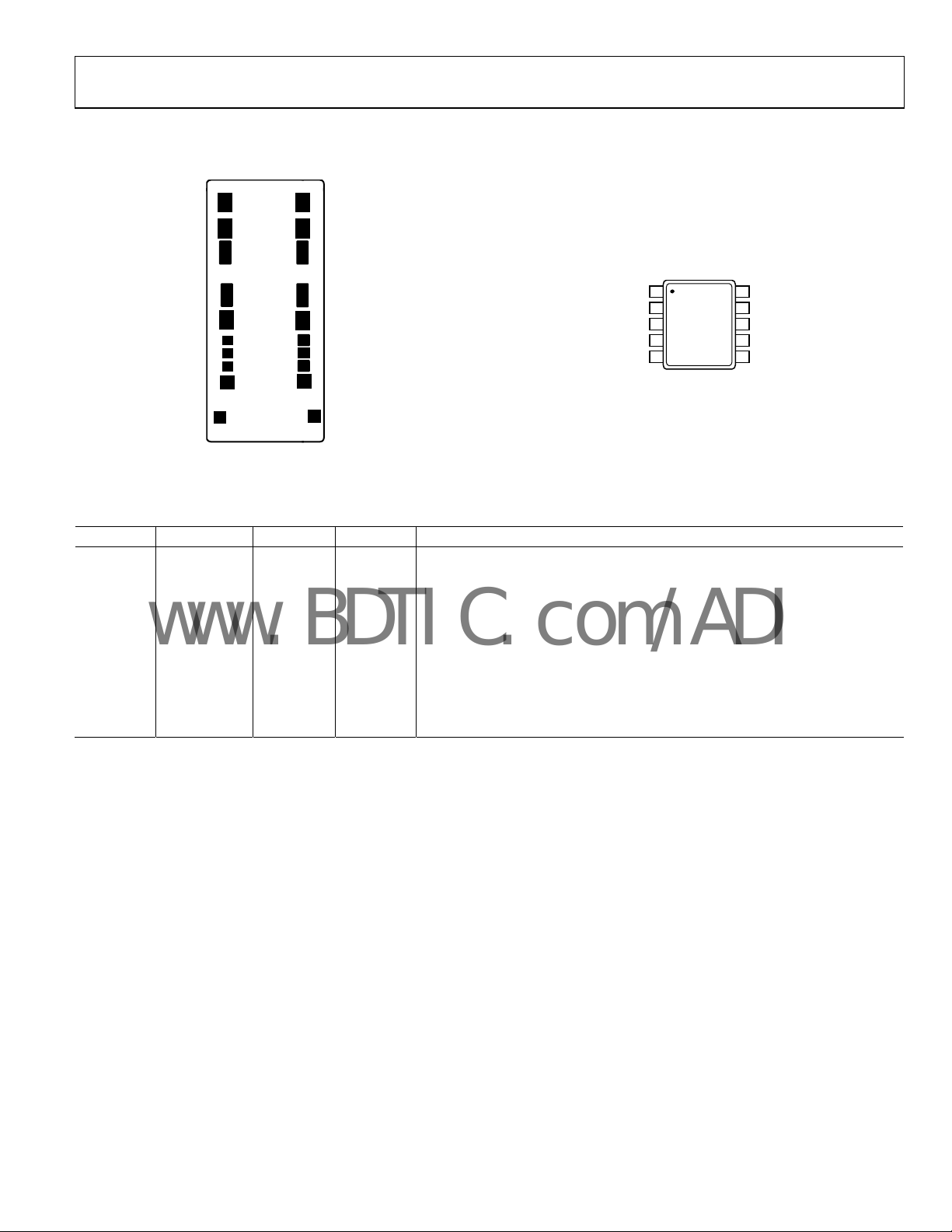
PIN CONFIGURATION AND FUNCTION DESCRIPTIONS
1
2
38
47
10
9
–IN2
1
+IN2
2
GND
OUT2
CF2
AD8213
3
TOP VIEW
(Not to Scale)
4
5
Figure 3. Pin Configuration
–IN1
10
+IN1
9
V+
8
7
OUT1
CF1
6
06639-003
5
Figure 2. Metallization Diagram
6
06639-002
Table 3. Pin Function Descriptions
Pin No. Mnemonic X Y Description
1 −IN2 −401 677 Inverting input of the second channel.
2 +IN2 −401 510 Noninverting input of the second channel.
3 GND −401 −53 Ground.
4 OUT2 −394 −500 Output of the second channel.
5 CF2 −448 −768 Low-pass filter pin for the second channel.
6 CF1 448 −768 Low-pass filter pin for the first channel.
7 OUT1 394 −500 Output of the first channel.
8 V+ 401 −61 Supply.
9 +IN1 401 510 Noninverting input of the first channel.
10 −IN1 401 677 Inverting input of the first channel.
Rev. 0 | Page 5 of 16

AD8213
–
www.BDTIC.com/ADI
TYPICAL PERFORMANCE CHARACTERISTICS
0.8
0.7
0.6
0.5
0.4
0.3
0.2
0.1
(mV)
0
OSI
–0.1
V
–0.2
–0.3
–0.4
–0.5
–0.6
–0.7
–0.8
Figure 4. Typical Offset Drift
130
COMMON-MO DE VOLTAG E > 5V
120
110
100
COMMON-MO DE VOLTAG E < 5V
90
CMRR (dB)
80
70
60
50
10 1M100k10k1k100
Figure 5. CMRR vs. Frequency
2500
2000
1500
1000
500
0
–500
GAIN ERROR (ppm)
–1000
–1500
–2000
–2500
TEMPERATURE (° C)
FREQUENCY (Hz)
TEMPERATURE (° C)
Figure 6. Typical Gain Drift
120–40 0–20 20406080100
06639-104
6639-005
120–40 0–20 20406080100
06639-102
40
35
30
25
20
15
10
5
0
–5
GAIN (dB)
–10
–15
–20
–25
–30
–35
–40
10k 100k 1M 10M
FREQUENCY (Hz)
06639-008
Figure 7. Typical Small Signal Bandwidth
= 200 mV p-p)
(V
OUT
10
9
8
7
6
5
4
3
OUTPUT ERROR ( %)
2
1
0
(% ERROR OF THE IDEAL OUTPUT VALUE)
–1
029590858075706560555045403530252015105
DIFFERENTIAL INPUT VOLTAGE (mV)
50
06639-013
Figure 8. Total Output Error vs. Differential Input Voltage
475
–480
–485
–490
–495
–500
–505
–510
–515
–520
INPUT BIAS CURRENT (nA)
–525
–530
–535
02
DIFFERENTIAL INPUT VOLTAGE (mV)
+IN
–IN
225200175150125100755025
50
06639-010
Figure 9. Input Bias Current vs. Differential Input Voltage
= 0 V) (Per Channel)
(V
CM
Rev. 0 | Page 6 of 16

AD8213
www.BDTIC.com/ADI
0.2
0
100mV/DIV
–0.2
–0.4
INPUT
OUTPUT
–0.6
–0.8
INPUT BIAS CURRENT (mA)
–1.0
–1.2
–5 6555453525155
INPUT COMMO N-MODE VO LTAGE (V)
Figure 10. Input Bias Current vs. Common-Mode Voltage
(Per Input)
7.0
6.5
6.0
5.5
5.0
4.5
4.0
3.5
3.0
SUPPLY CURRENT (mA)
2.5
2.0
1.5
1.0
–4 –2 0 2 4 6 8 65
COMMON-MODE VOLTAGE (V)
Figure 11. Supply Current vs. Common-Mode Voltage
1V/DIV, CF = 20pF
1V/DIV, C
06639-011
= 100pF
F
TIME (2µs/DIV)
OUTPUT
06639-015
Figure 13. Rise Time
200mV/DIV
INPUT
2V/DIV, C
= 20pF
F
OUTPUT
06639-012
TIME (1µs/DIV)
06639-016
Figure 14. Differential Overload Recovery (Falling)
100mV/DIV
1V/DIV, CF = 20pF
1V/DIV, C
= 100pF
F
INPUT
OUTPUT
OUTPUT
TIME (2µs/DIV)
Figure 12. Fall Time
06639-014
Rev. 0 | Page 7 of 16
INPUT
200mV/DIV
OUTPUT
= 20pF
2V/DIV, C
F
TIME (1µs/DIV)
Figure 15. Differential Overload Recovery (Rising)
06639-017

AD8213
www.BDTIC.com/ADI
12
2V/DIV
0.01/DIV
TIME (5µs/DIV)
Figure 16. Settling Time (Falling)
2V/DIV
0.01/DIV
TIME (5µs/DIV)
Figure 17. Settling Time (Rising)
12
11
10
9
8
7
6
5
4
3
2
MAXIMUM OUT PUT SINK CURRENT ( mA)
1
0
–40 –20 0 20 40 60 80 100 120 140
TEMPERATURE (° C)
Figure 18. Output Sink Current vs. Temperature
(Per Chan
nel)
06639-105
06639-106
06639-020
11
10
9
8
7
6
5
4
3
2
1
MAXIMUM OUT PUT SOURCE CURRENT (mA)
0
–40 –20 0 20 40 60 80 100 120 140
TEMPERATURE (° C)
Figure 19. Output Source Current vs. Temperature
(Per Chan
5.0
4.9
4.8
4.7
4.6
4.5
4.4
4.3
4.2
4.1
4.0
3.9
OUTPUT VO LTAGE RANG E (V)
3.8
3.7
3.6
3.5
077.06.56.05.55.04.54.03.53.02.52.01.51.00.5
OUTPUT SO URCE CURRENT (mA)
nel)
Figure 20. Output Voltage Range vs. Output Source Current
(Per Chan
2.0
1.8
1.6
1.4
1.2
1.0
0.8
0.6
0.4
0.2
OUTPUT VO LTAGE RANG E FROM GND (V)
0
01987654321
OUTPUT SI NK CURRENT (mA)
Figure 21. Output Voltage Range from
nel)
GND vs. Output Sink Current
(Per Channel)
06639-021
.5
06639-023
0
06639-024
Rev. 0 | Page 8 of 16

AD8213
www.BDTIC.com/ADI
1000
800
2100
1800
1500
TEMP = –40°C
TEMP = +25°C
TEMP = +125°C
600
COUNT
400
200
0
–15 151050–5–10
1400
1200
1000
800
COUNT
600
400
200
0
VOS (µV/°C)
Figure 22. Offset Drift Distribution (μV/°C)
(Temp
erature Range = −40°C to +125°C)
GAIN DRIFT (ppm/°C)
Figure 23. Gain Drift Distribution (ppm/°C)
(Temperature Range = −40°C to +125°C)
1200
COUNT
900
600
300
0
06639-006
VOS (mV)
2.0–2.0 –1.5 –1.0 –0.5 0 0.5 1.0 1.5
06639-103
Figure 24. Offset Distribution (mV)
= 6 V)
(V
CM
0–3–6–9–12–15–18–21–24
06639-101
Rev. 0 | Page 9 of 16

AD8213
O
www.BDTIC.com/ADI
THEORY OF OPERATION
In typical applications, the AD8213 amplifies a small differential
input voltage generated by the load current flowing through a
shunt resistor. The AD8213 rejects high common-mode
voltages (up to 65 V) and provides a ground referenced, buffered
output that interfaces with an analog-to-digital converter (ADC).
Figure 25 shows a simplified schematic of the AD8213.
The following explanation refers exclusively to Channel 1 of the
AD8213,
however, the same explanation applies to Channel 2.
A load current flowing through the external shunt resistor
p
roduces a voltage at the input terminals of the AD8213. The
input terminals are connected to Amplifier A1 by Resistor R1
and Resistor R1
input impedance is held to (V
negligible current flows through Resistor R1
. The inverting terminal, which has very high
(2)
CM
) – (I
SHUNT
× R
SHUNT
. Amplifier A1
(2)
), since
(1)
forces the noninverting input to the same potential. Therefore,
the current that flows through Resistor R1
I
IN1
= (I
SHUNT1
× R
SHUNT1
)/R1
(1)
, is equal to
(1)
I
SHUNT2
R
SHUNT2
R2
(1)
R2
(2)
I
IN2IIN1
This current (I
output buffer amplifier has a gain of 20 V/V, and offers excellent
accuracy as the internal gain setting resistors are precision
trimmed to within 0.01% matching. The resulting output
voltage is equal to
V
OUT1
Prior to the buffer amplifier, a precision-trimmed 20 kΩ re
is available to perform low-pass filtering of the input signal
prior to the amplification stage. This means that the noise of the
input signal is not amplified, but rejected, resulting in a more
precise output signal that will directly interface with a converter.
A capacitor from the CF1 pin to GND, will result in a low-pass
filter with a corner frequency of
f
3
−
dB
I
SHUNT1
R
SHUNT1
R1
(1)
) is converted back to a voltage via R
IN1
= (I
=
R1
× R
SHUNT1
1
()
C
200002
π
(2)
SHUNT1
FILTER
) × 20
OUT1
. The
sistor
UT2 = (I
SHUNT2
× R
SHUNT2
) × 20
PROPRIETARY
OFFSET
CIRCUITRY
G = +20
A2
R
OUT2
CF2
Figure 25. Simplifi
Q2
A1
Q1
20kΩ20kΩ
R
OUT1
ed Schematic
PROPRIETARY
OFFSET
CIRCUITRY
G = +20
AD8213
CF1GND
V+
OUT1 = (I
SHUNT1
× R
SHUNT1
) × 20
06639-028
Rev. 0 | Page 10 of 16

AD8213
V
www.BDTIC.com/ADI
APPLICATION NOTES
OUTPUT LINEARITY
In all current sensing applications, and especially in automotive
and industrial environments where the common-mode voltage
can vary significantly, it is important that the current sensor
maintain the specified output linearity, regardless of the input
differential or common-mode voltage. The AD8213 contains
specific circuitry on the input stage, which ensures that even
when the differential input voltage is very small, and the
common-mode voltage is also low (below the 5 V supply), the
input to output linearity is maintained.
put differential voltage versus the corresponding output
in
voltage at different common modes.
220
200
180
160
140
120
(mV)
100
OUT
V
V
@ VCM = 0V
OUT
80
60
40
20
0
012345678910
Figure 26. Gain Linearity Due to Differential and Common-Mode Voltage
IDEAL V
OUT
VIN DIFFERENTIAL (mV)
The AD8213 provides a correct output voltage, regardless of the
common mode, when the input differential is at least 2 mV.
This is due to the voltage range of the output amplifier that can
go as low as 33 mV typical. The specified minimum output
amplifier voltage is 100 mV in order to provide sufficient
guardbands. The ability of the AD8213 to work with very small
differential inputs regardless of the common-mode voltage,
allows for more dynamic range, accuracy, and flexibility in any
current sensing application.
Figure 26 displays the
V
@ VCM = 65V
OUT
06639-029
LOW-PASS FILTERING
In typical applications, such as motor and solenoid current
sensing, filtering the differential input signal of the AD8213
could be beneficial in reducing differential common-mode
noise as well as transients and current ripples flowing through
the input shunt resistor. Typically, such a filter can be implemented by adding a resistor in series with each input and a
capacitor directly between the input pins. However, the AD8213
features a filter pin available after the input stage, but before the
final amplification stage. The user can connect a capacitor to
ground, making a low-pass filter with the internal precisiontrimmed 20 kΩ resistor. This means the no gain or CMRR
errors are introduced by adding resistors at the input of the
AD8213.
The 3 dB frequency of this low-pass filter is calculated using the
following formula:
It is recommended that in order to prevent output chatter due
t
o noise potentially entering through the filter pin and coupling
to the output, a capacitor is always placed from the filter pin to
GND. This can be a ≈20 pF capacitor in cases when all of the
bandwidth of the AD8213 is needed in the application.
Figure 27 shows the typical connection.
GND
I
SHUNT1
R
SHUNT1
R1
(1)
A1
20kΩ20kΩ
I
SHUNT2
R
SHUNT2
R2
(1)
PROPRIETARY
OFFSET
CIRCUIT RY
G = +20
CF2 CF1
CAP2 CAP1
=
f
3
−
dB
R2
(2)
A2
Figure 27. Filter Capacitor Connections
1
()
C
200002
π
FILTER
R1
(2)
PROPRIETARY
OFFSET
CIRCUITRY
G = +20
AD8213
+
6639-030
Rev. 0 | Page 11 of 16

AD8213
www.BDTIC.com/ADI
APPLICATIONS INFORMATION
HIGH-SIDE CURRENT SENSE WITH A LOW-SIDE SWITCH
In such load control configurations, the PWM controlled switch
is ground referenced. An inductive load (solenoid) is tied to a
power supply. A resistive shunt is placed between the switch and
the load (see Figure 28). An advantage of placing the shunt on
t
he high side is that the entire current, including the recirculation current, can be measured, because the shunt remains in
the loop when the switch is off. In addition, diagnostics can be
enhanced because shorts to ground can be detected with the
shunt on the high side. In this circuit configuration, when the
switch is closed, the common-mode voltage moves down to
near the negative rail. When the switch is opened, the voltage
reversal across the inductive load causes the common-mode
voltage to be held one diode drop above the battery by the
clamp diode.
INDUCTIVE
BATTERY
CLAMP
DIODE
SWITCH
LOAD
SHUNT
1
2
3
4
5
AD8213
–IN2
+IN2
GND
OUT2
CF2
–IN1
+IN1
V+
OUT1
CF1
CAP1CAP2
Figure 28. Low-Side Switch
HIGH-SIDE CURRENT SENSING
In this configuration, the shunt resistor is referenced to the
battery. High voltage will be present at the inputs of the current
sense amplifier. In this mode, the recirculation current is again
measured and shorts to ground can be detected. When the
shunt is battery referenced the AD8213 produces a linear
ground referenced analog output. An
o provide an overcurrent detection signal in as little as 100 ns.
t
This feature will be useful in high current systems, where fast
shutdown in overcurrent conditions is essential.
INDUCTIVE
LOAD
10
9
8
7
6
CLAMP
DIODE
5V
SHUNT
BATTERY
SWITCH
AD8214 can also be used
OVERCURRENT
DETECTION ( <100ns)
8
–IN7NC6GND5OUT
AD8214
V
+IN3V
2
GND
AD8214
V
REG
3
–IN1 10
+IN1 9
V+ 8
OUT1
CF1
REG
+IN
CAP1
NC
4
8
7NC6
–IN
V
S
1
2
SHUNT
LOAD
5V
7
6
SWITCH
BATTERY
06639-032
S
1
OVERCURRENT
DETECTION (< 100ns)
5
OUT
NC
4
SHUNT
LOAD
BATTERY
SWITCH
CAP2
4
5
AD8213
–IN21
+IN22
GND3
OUT2
CF2
Figure 29. Battery Referenced Shunt Resistor
LOW-SIDE CURRENT SENSING
In systems where low-side current sensing is preferred, the
06639-031
AD8213 provides an integrated solution with great accuracy.
Ground noise is rejected, CMRR is typical higher than 90 dB, and
output linearity is not compromised, regardless of the input
differential voltage.
BATTERY
INDUCTIVE
CLAMP
DIODE
SWITCH
SHUNT
LOAD
1
2
3
4
5
AD8213
–IN2
+IN2
GND
OUT2
CF2
–IN1
+IN1
OUT1
CF1
10
9
V+
8
7
6
Figure 30. Ground Referenced Shunt Resistor
INDUCTIVE
LOAD
CLAMP
DIODE
5V
SWITCH
SHUNT
BATTERY
06639-033
Rev. 0 | Page 12 of 16

AD8213
www.BDTIC.com/ADI
BIDIRECTIONAL CURRENT SENSING
The AD8213 can also be configured to sense current in both
directions at the inputs. This configuration is useful in charge/
discharge applications. A typical connection diagram is shown
in
Figure 31. In this mode Channel 1 monitors I
Channel 2 monitors I
BATTERY
CHARGE
I
CHARGE
I
LOAD
R
SHUNT
.
LOAD CHARGER
AD8213
1
–IN2
2
+IN2
3
GND
4
OUT2
5
CF2
CF2 CF1
–IN1
+IN1
OUT1
CF1
10
9
5V
8
V+
7
6
Figure 31. Bidirectional Current Sensing
For applications requiring a bidirectional current measurement,
an optimal solution could be to use a single channel device,
which offers the same functionality as the previous circuit. The
AD8210 is a single channel current sensor featuring bidirec-
ional capability. The typical connection diagram for the
t
AD8210 in bidirectional applications is shown in
and
LOAD
Figure 32.
06639-034
BATTERY
I
CHARGE
I
LOAD
R
SHUNT
+IN –IN
LOAD CHARGER
V+
AD8210
0.1µF
1
OUTPUT
2
GND
V
G = +20
V
REF
REF
Figure 32. AD8210 in Bidirectional Applications
06639-035
Rev. 0 | Page 13 of 16

AD8213
www.BDTIC.com/ADI
OUTLINE DIMENSIONS
3.10
3.00
2.90
6
10
3.10
3.00
2.90
1
PIN 1
0.50 BSC
0.95
0.85
0.75
0.15
0.05
0.33
0.17
COPLANARITY
0.10
COMPLIANT TO JEDEC STANDARDS MO-187-BA
Figure 33. 10-Lead Mini Small Outline Package [MSOP]
ORDERING GUIDE
Model Temperature Range Package Description Package Option Branding
AD8213YRMZ
AD8213YRMZ-RL
AD8213YRMZ-RL7
1
Z = RoHS Compliant Part.
1
1
1
−40°C to +125°C 10-Lead MSOP RM-10 HOU
−40°C to +125°C 10-Lead MSOP, 13” Tape and Reel RM-10 HOU
−40°C to +125°C 10-Lead MSOP, 7” Tape and Reel RM-10 HOU
5.15
4.90
4.65
5
1.10 MAX
SEATING
PLANE
0.23
0.08
8°
0°
(RM-10)
Dimensions shown in millimeters
0.80
0.60
0.40
Rev. 0 | Page 14 of 16

AD8213
www.BDTIC.com/ADI
NOTES
Rev. 0 | Page 15 of 16

AD8213
www.BDTIC.com/ADI
NOTES
©2007 Analog Devices, Inc. All rights reserved. Trademarks and
registered trademarks are the property of their respective owners.
D06639-0-5/07(0)
Rev. 0 | Page 16 of 16
 Loading...