


3 V/5 V Low Power, Synchronous
a
FEATURES
Synchronous Operation
Full-Scale Frequency Set by External System Clock
8-Lead SOT-23 and 8-Lead microSOIC Packages
3 V or 5 V Operation
Low Power: 3 mW (Typ)
Nominal Input Range: 0 to V
True –150 mV Capability Without Charge Pump
V
Range: 2.5 V to VDD
REF
Internal 2.5 V Reference
1 MHz Max Input Frequency
Selectable High Impedance Buffered Input
Minimal External Components Required
APPLICATIONS
Isolation of High Common-Mode Voltages
Low-Cost Analog-to-Digital Conversion
Battery Monitoring
Automotive Sensing
GENERAL DESCRIPTION
The AD7740 is a low-cost, ultrasmall synchronous Voltage-toFrequency Converter (VFC). It works from a single 3.0 V to
3.6 V or 4.75 V to 5.25 V supply consuming 0.9 mA. The AD7740
is available in an 8-lead SOT-23 and also in an 8-lead microSOIC
package. Small package, low cost and ease of use were major
design goals for this product. The part contains an on-chip 2.5 V
bandgap reference but the user may overdrive this using an
external reference. This external reference range includes VDD.
The full-scale output frequency is synchronous with the clock
signal on the CLKIN pin. This clock can be generated with the
addition of an external crystal (or resonator) or supplied from a
CMOS-compatible clock source. The part has a maximum
input frequency of 1 MHz.
For an analog input signal that goes from 0 V to V
put frequency goes from 10% to 90% of f
the part provides a very high input impedance and accepts a
range of 0.1 V to VDD – 0.2 V on the VIN pin. There is also
an unbuffered mode of operation that allows VIN to go from
–0.15 V to VDD + 0.15 V. The modes are interchangeable using
the BUF pin.
The AD7740 (Y Grade) is guaranteed over the automotive
temperature range of –40°C to +105°C. The AD7740 (K Grade)
is guaranteed from 0°C to 85°C.
REF
REF
In buffered mode,
CLKIN.
, the out-
Voltage-to-Frequency Converter
AD7740*
FUNCTIONAL BLOCK DIAGRAM
REFIN/OUT
AD7740
VIN
PRODUCT HIGHLIGHTS
X1
BUF
VOLTAGE-TO-
GND
REFERENCE
FREQUENCY
MODULATOR
GENERATION
CLKOUT
1. The AD7740 is a single channel, single-ended VFC. It is
available in 8-lead SOT-23 and 8-lead microSOIC packages,
and is intended for low-cost applications. The AD7740 offers
considerable space saving over alternative solutions.
2. The AD7740 operates from a single 3.0 V to 3.6 V or 4.75 V
to 5.25 V supply and consumes typically 0.9 mA when the
input is unbuffered. It also contains an automatic power-down
function.
3. The AD7740 does not require external resistors and capacitors to set the output frequency. The maximum output
frequency is set by a crystal or a clock. No trimming or calibration is required.
4. The analog input can be taken to 150 mV below GND for
true bipolar operation.
5. The specified voltage reference range on REFIN is from
2.5 V to the supply voltage, VDD.
VDD
2.5V
FOUT
CLOCK
CLKIN
*Patents pending.
REV. 0
Information furnished by Analog Devices is believed to be accurate and
reliable. However, no responsibility is assumed by Analog Devices for its
use, nor for any infringements of patents or other rights of third parties
which may result from its use. No license is granted by implication or
otherwise under any patent or patent rights of Analog Devices.
One Technology Way, P.O. Box 9106, Norwood, MA 02062-9106, U.S.A.
Tel: 781/329-4700 World Wide Web Site: http://www.analog.com
Fax: 781/326-8703 © Analog Devices, Inc., 2000

(VDD = 3.0 V to 3.6 V, 4.75 V to 5.25 V, GND = 0 V, REFIN = 2.5 V; CLKIN = 1 MHz; All
AD7740 SPECIFICATIONS
Parameter
2
DC PERFORMANCE
Integral Nonlinearity
CLKIN = 32 kHz
CLKIN = 1 MHz ± 0.012 % of Span Unbuffered Mode, Crystal at CLKIN
CLKIN = 32 kHz
3
3
CLKIN = 1 MHz ± 0.018 % of Span Buffered Mode, Crystal at CLKIN
Offset Error ± 7 ± 35 mV Unbuffered Mode, VIN = 0 V
Gain Error ± 0.1 ± 0.7 % of Span
Offset Error Drift
Gain Error Drift
Power Supply Rejection Ratio
3
3
3
ANALOG INPUT, VIN
Nominal Input Span 0 – V
Input Current 8 10 µA Unbuffered Mode, VIN = 5.4 V, REFIN = 5.25 V
REFERENCE VOLTAGE
REFIN
5
Nominal Input Voltage 2.5 VDD V
REFOUT
Output Voltage 2.3 2.5 2.7 V
Output Impedance
Reference Drift
Line Rejection
Line Rejection
3
3
3
3
Reference Noise (0.1 Hz to 10 Hz)
FOUT OUTPUT
Nominal Frequency Span 0.1 f
LOGIC INPUTS (CLKIN, BUF)
3
CLKIN
Input frequency 32 1000 kHz For Specified Performance
Input High Voltage, V
Input High Voltage, V
Input Low Voltage, V
Input Low Voltage, V
Input Current ± 2 µA VIN = 0 V to V
IH
IH
IL
IL
Pin Capacitance 3 10 pF
BUF
Input High Voltage, V
Input High Voltage, V
Input Low Voltage, V
Input Low Voltage, V
Input Current ± 100 nA
IH
IH
IL
IL
Pin Capacitance 3 10 pF
LOGIC OUTPUTS (FOUT, CLKOUT)
Output High Voltage, V
Output High Voltage, V
Output Low Voltage, V
POWER REQUIREMENTS
7
V
DD
I
(Normal Mode)
DD
I
(Normal Mode)
DD
I
(Power-Down) 30 100 µA
DD
Power-Up Time
NOTES
1
Temperature range: K Version, 0°C to +85°C; Y Version, –40°C to +105°C; typical specifications are at 25°C.
2
See Terminology.
3
Guaranteed by design and characterization, not production tested.
4
Span = Max output frequency–Min output frequency.
5
Because this pin is bidirectional, any external reference must be capable of sinking/sourcing 400 µA in order to overdrive the internal reference.
6
These logic levels apply to CLKOUT only when it is loaded with one CMOS load.
7
Operation at VDD = 2.7 V is also possible with degraded specifications.
8
Outputs unloaded. IDD increases by CL × V
type (see Clock Generation section).
Specifications subject to change without notice.
OH
OH
OL
8
8
3
OUT
K, Y Versions
Min Typ Max Unit Test Conditions/Comments
0.1 VDD – 0.2 V Buffered Mode
3
3.5 V VDD = 5 V ± 5%
2.5 V VDD = 3.3 V ± 10%
2.4 V VDD = 5 V ± 5%
2.1 V VDD = 3.3 V ± 10%
3
4.0 V Output Sourcing 200 µA6. VDD = 5 V ± 5%
2.1 V Output Sourcing 200 µA6. VDD = 3.3 V ± 10%
3.0 5.25 V
× f
when FOUT is loaded. If using a crystal/resonator as the clock source, IDD will vary depending on the crystal/resonator
FOUT
specifications T
1
± 0.012 % of Span
MIN
to T
unless otherwise noted.)
MAX
4
Unbuffered Mode, External Clock at CLKIN
± 0.018 % of Span Buffered Mode, External Clock at CLKIN
± 7 ± 35 mV Buffered Mode, VIN = 0.1 V
± 20 µV/°C
± 4 ppm of Span/°C
–55 dB ∆VDD = ± 5% (5 V)
–65 dB ∆VDD = ± 10% (3.3 V)
REF
V ± 150 mV Overrange Available
5 100 nA Buffered Mode, VIN = 0.1 V, REFIN = 2.5 V
1kΩ See Pin Function Description
± 50 ppm/°C
–75 dB ∆VDD = ± 5% (5 V)
–60 dB ∆VDD = ± 10% (3.3 V)
100 µV p–p
CLKIN
to 0.9 f
CLKIN
Hz VIN = 0 V to V
. See Figure 2
REF
0.8 V VDD = 5 V ± 5%
0.4 V VDD = 3.3 V ± 10%
DD
0.8 V VDD = 5 V ± 5%
0.4 V VDD = 3.3 V ± 10%
0.1 0.4 V Output Sinking 1.6 mA
6
0.9 1.25 mA VIH = VDD, VIL= GND. Unbuffered Mode
1.1 1.5 mA VIH = VDD, VIL= GND. Buffered Mode
30 µs Exiting Power-Down (Ext. Clock at CLKIN)
–2–
REV. 0
AD7740
MAX
1, 2, 3
(VDD = 3.0 V to 3.6 V, 4.75 V to 5.25 V, GND = O V, REFIN = 2.5 V)
Limit at T
MIN
, T
MAX
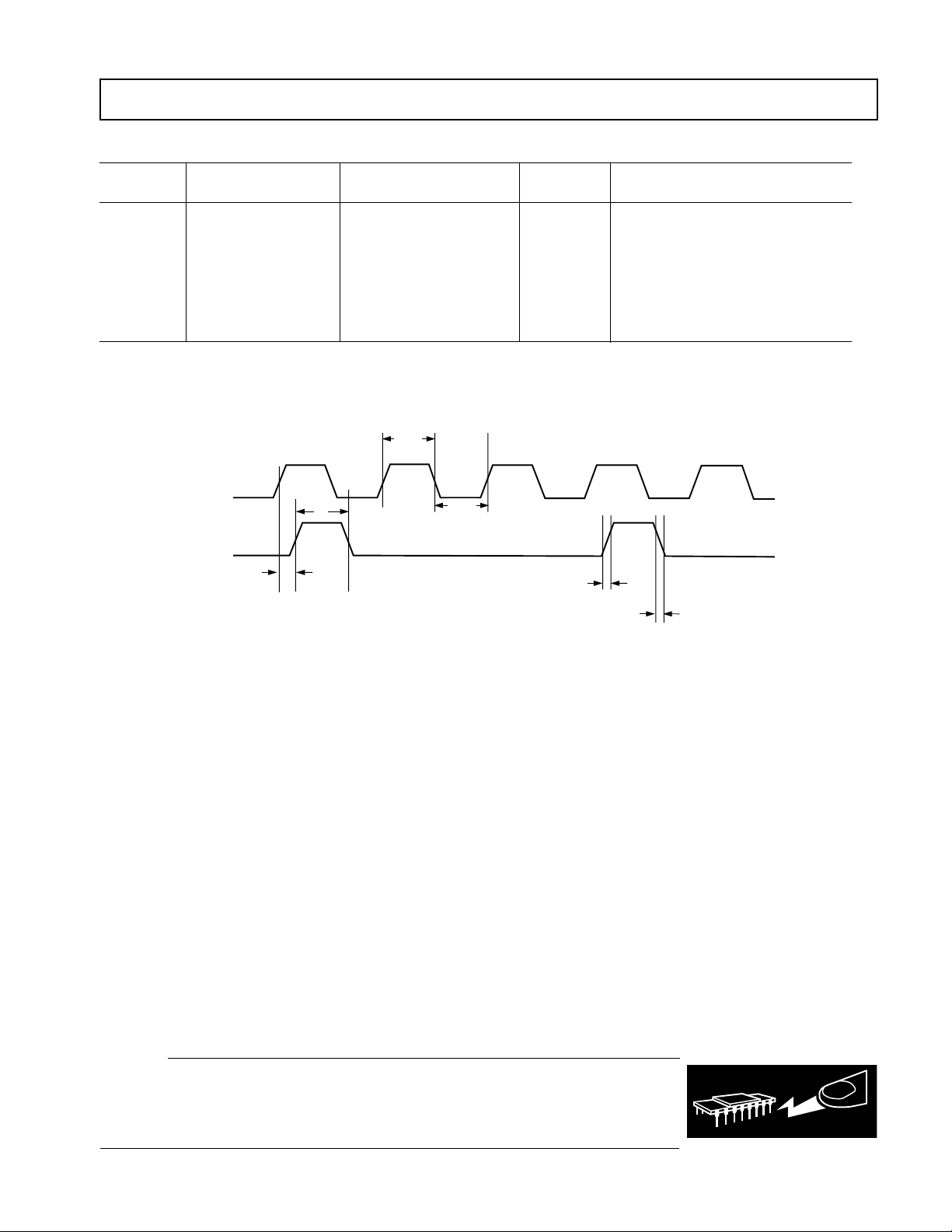
TIMING CHARACTERISTICS
Limit at T
MIN
, T
Parameter VDD = 3.0 V to 3.6 V VDD = 4.75 V to 5.25 V Unit Conditions/Comments
f
CLKIN
32 32 kHz min Clock Frequency
1 1 MHz max
t
HIGH:tLOW
40:60 40:60 min Clock Mark/Space Ratio
60:40 60:40 max
t
1
t
2
t
3
t
4
NOTES
1
Guaranteed by design and characterization, not production tested.
2
All input signals are specified with tr = tf = 5 ns (10% to 90% of VDD) and timed from a voltage level of (V
3
See Figure 1.
Specifications subject to change without notice
50 35 ns typ CLKIN Edge to FOUT Edge Delay
2.3 1.8 ns typ FOUT Rise Time
1.6 1.4 ns typ FOUT Fall Time
t
HIGH
CLKIN
FOUT
± 20
t
t
1
t
± 8
HIGH
t
HIGH
t
4
LOW
ns typ FOUT Pulsewidth
+ VIH)/2.
IL
t
2
t
3
Figure 1. Timing Diagram
ABSOLUTE MAXIMUM RATINGS*
(TA = 25°C unless otherwise noted)
VDD to GND . . . . . . . . . . . . . . . . . . . . . . . . . –0.3 V to +7 V
Analog Input Voltage to GND . . . . . . . . –0.3 V to V
Reference Input Voltage to GND . . . . . –0.3 V to V
+ 0.3 V
DD
+ 0.3 V
DD
Logic Input Voltage to GND . . . . . . . . –0.3 V to VDD + 0.3 V
FOUT Voltage to GND . . . . . . . . . . . –0.3 V to VDD + 0.3 V
Operating Temperature Range
Commercial (K Version) . . . . . . . . . . . . . . . . 0°C to +85°C
Automotive (Y Version) . . . . . . . . . . . . . . –40°C to +105°C
Storage Temperature Range . . . . . . . . . . . . –65°C to +150°C
Junction Temperature (T
Max) . . . . . . . . . . . . . . . . . . 150°C
J
SOT-23 Package
Power Dissipation . . . . . . . . . . . . . . . . . . (T
Max – TA)/θ
J
microSOIC Package
Power Dissipation . . . . . . . . . . . . . . . . . (T
θJA Thermal Impedance . . . . . . . . . . . . . . . . . . . . . 206°C/W
Thermal Impedance . . . . . . . . . . . . . . . . . . . . . . 44°C/W
θ
JC
Lead Temperature (10 secs) . . . . . . . . . . . . . . . . . . . 300°C
Reflow Soldering
Peak Temperature . . . . . . . . . . . . . . . . . . . . . . 220 +5/0°C
Time at Peak Temperature . . . . . . . . . . . . . 10 sec to 40 sec
*Stresses above those listed under Absolute Maximum Ratings may cause perma-
nent damage to the device. This is a stress rating only; functional operation of the
device at these or any other conditions above those listed in the operational
sections of this specification is not implied. Exposure to absolute maximum rating
conditions for extended periods may affect device reliability.
JA
θJA Thermal Impedance . . . . . . . . . . . . . . . . . . . . . 240°C/W
Lead Temperature (10 secs) . . . . . . . . . . . . . . . . . . 300°C
Reflow Soldering
Peak Temperature . . . . . . . . . . . . . . . . . . . . 220 + 5/0°C
Time at Peak Temperature . . . . . . . . . . . . 10 sec to 40 sec
CAUTION
ESD (electrostatic discharge) sensitive device. Electrostatic charges as high as 4000 V readily
accumulate on the human body and test equipment and can discharge without detection. Although
the AD7740 features proprietary ESD protection circuitry, permanent damage may occur on
devices subjected to high-energy electrostatic discharges. Therefore, proper ESD precautions are
recommended to avoid performance degradation or loss of functionality.
WARNING!
Max – TA)/θ
J
ESD SENSITIVE DEVICE
JA
REV. 0
–3–
AD7740
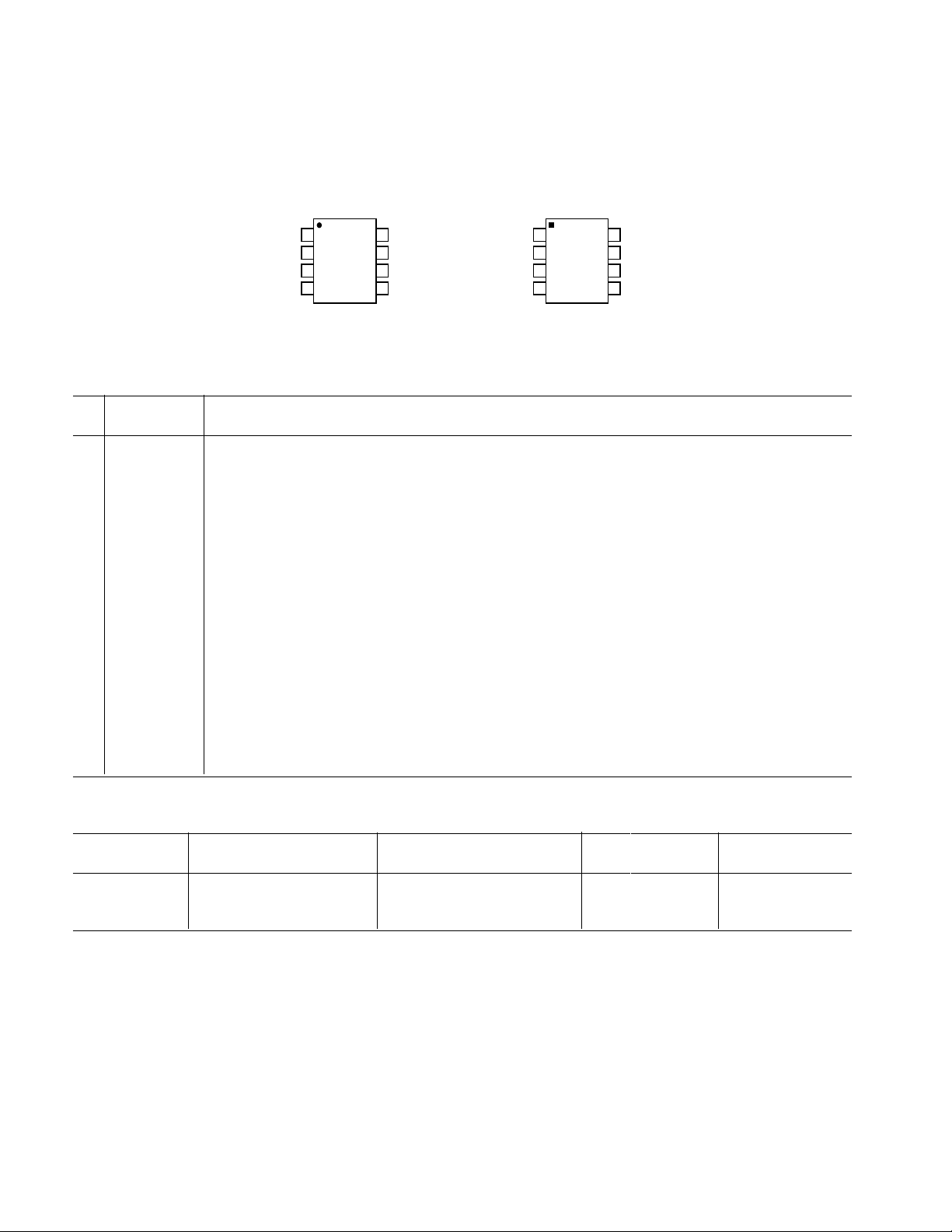
PIN CONFIGURATIONS
8-Lead microSOIC
1
CLKOUT
2
CLKIN
REFIN/OUT
GND
microSOIC
TOP VIEW
3
(Not to Scale)
4
AD7740
8
BUF
7
FOUT
6
VDD
5
VIN
8-Lead SOT-23
1
BUF
AD7740
2
FOUT
VDD
VIN
SOT-23
3
TOP VIEW
(Not to Scale)
4
8
CLKOUT
7
CLKIN
6
GND
5
REFIN/OUT
PIN FUNCTION DESCRIPTIONS
8-LEAD microSOIC PIN NUMBERS*
Pin
No. Mnemonic Function
1 CLKOUT The crystal/resonator is tied between this pin and CLKIN. In the case of an external clock driving CLKIN, an
inverted clock signal appears on this pin and can be used to drive other circuitry provided it is buffered first.
2 CLKIN The master clock for the device may be in the form of a crystal/resonator tied between this pin and CLKOUT.
An external CMOS-compatible clock may also be applied to this input as the clock for the device. If CLKIN
is inactive low for 1 ms (typ), the AD7740 automatically enters power-down.
3 GND Ground reference for all the circuitry on-chip.
4 REFIN/OUT Voltage Reference Input. This is the reference input to the core of the VFC and defines the span of the VFC.
If this pin is left unconnected, the internal 2.5 V reference is the default reference. Alternatively, a precision
external reference may be used to overdrive the internal reference. The internal reference has high output
impedance in order to allow it to be overdriven.
5 VIN The analog input to the VFC. It has a nominal input range from 0 V to V
frequency of 10% f
CLKIN
to 90% f
. It has a ± 150 mV overrange. If buffered, it draws virtually no current
CLKIN
which corresponds to an output
REF
from whatever source is driving it.
6 VDD Power Supply Input. These parts can be operated at 3.3 V ± 10% or 5 V ± 5%. The supply should be
adequately decoupled with a 10 µF and a 0.1 µF capacitor to GND.
7 FOUT Frequency Output. FOUT goes from 10% to 90% of f
, depending on VIN.
CLKIN
8 BUF Buffered Mode Select Pin. When BUF is tied low, the VIN input is unbuffered and the range on the VIN
pin is –0.15 V to VDD + 0.15 V. When it is tied high, VIN is buffered and the range on the VIN pin
is restricted to 0.1 V to VDD – 0.2 V.
*Note that the SOT-23 and microSOIC packages have different pinouts.
ORDERING GUIDE
Package Branding
Model Temperature Range Package Description Option Information
AD7740KRM 0°C to 85°C microSOIC Package RM-8 VOK
AD7740YRT –40°C to +105°C SOT-23 Package RT-8 VOY
AD7740YRM –40°C to +105°C microSOIC Package RM-8 VOY
–4–
REV. 0

AD7740
TERMINOLOGY
INTEGRAL NONLINEARITY
For the VFC, Integral Nonlinearity (INL) is a measure of the maximum deviation from a straight line passing through the actual
endpoints of the VFC transfer function. The error is expressed in
% of the actual frequency span:
Frequency Span = FOUT(max) – FOUT(min)
OFFSET ERROR
Ideally, the output frequency for 0 V input voltage is 10% of
in unbuffered mode. The deviation from this value referred
f
CLKIN
to the input is the offset error at BUF = 0. In buffered mode the
minimum output frequency (corresponding to 0.10 V minimum
at V
input voltage) is 13.2% of f
CLKIN
= 2.5 V. The deviation
REF
from this value referred to the input is the offset error at BUF = 1.
Offset error is expressed in mV.
GAIN ERROR
This is a measure of the span error of the VFC. The gain is the
scale factor that relates the input VIN to the output FOUT.
The gain error is the deviation in slope of the actual VFC transfer
characteristic from the ideal expressed as a percentage of the fullscale span. See Figure 2.
OFFSET ERROR DRIFT
This is a measure of the change in Offset Error with changes in
temperature. It is expressed in µV/°C.
POWER SUPPLY REJECTION RATIO (PSRR)
This indicates how the apparent input voltage of the VFC is
affected by changes in the supply voltage. The input voltage is
kept constant at 2 V, V
is 2.5 V and the VDD supply is varied
REF
⫾10% at 3.3 V and ±5% at 5 V. The ratio of the apparent change
in input voltage to the change in VDD is measured in dBs.
OUTPUT
FREQUENCY
FOUT
0.9 f
CLKIN
GAIN ERROR
IDEAL
WITH OFFSET
ERROR ONLY
WITH OFFSET
ERROR AND
GAIN ERROR
INPUT
VOLTAGE
VIN
f
CLKIN
0.1
0
OFFSET
ERROR
REFIN
Figure 2. Offset and Gain
GAIN ERROR DRIFT
This is a measure of the change in Gain Error with changes in
temperature. It is expressed in (ppm of span)/°C.
REV. 0
–5–

AD7740–Typical Performance Characteristics
0.015
0.01
0.005
–0.005
INL ERROR – % of Span
–0.01
–0.015
BUFFER OFF
0
–0.5 0 0.5
BUFFER ON
VIN – V
VDD = 5V
REFIN = 2.5V
CLKIN = 1MHz
= 25C
T
A
1.51
2
2.5
TPC 1. INL vs. VIN (Buffered and
Unbuffered)
12
REFIN = 2.5V
CLKIN = 1MHz
= 25C
T
8
A
BUF = 0
4
0
OFFSET ERROR – mV
–4
–8
03 6
GAIN ERROR
GAIN ERROR
OFFSET ERROR
45
VDD – V
0.08
0.04
0
–0.04
–0.08
–0.12
TPC 4. Offset and Gain Error vs. VDD
–4
VDD = 5V
REFIN = 2.5V
T
= 25C
A
–5
–6
OFFSET ERROR – mV
–7
–8
0 200 1000
BUFFER ON
BUFFER OFF
400
CLKIN FREQUENCY – kHz
600 800
TPC 2. Offset Error vs. CLKIN
(Buffered and Unbuffered)
GAIN ERROR – % Span
–50
–60
PSRR – dB
–70
–80
–1
BUFFER ON
VDD = 5V
REFIN = 4.75V
CLKIN = 1MHz
T
= 25C
A
0
1
BUFFER OFF
23
VIN – V
TPC 5. PSRR vs. VIN (Buffered and
Unbuffered)
0.1
BUFFER
OFF
0.05
BUFFER ON
0
GAIN ERROR – % Span
–0.05
–0.1
200 800
0
400 1000
CLKIN FREQUENCY – kHz
VDD = 5V
REFIN = 2.5V
T
= 25C
A
600
TPC 3. Gain Error vs. CLKIN
(Buffered and Unbuffered)
1.25
1
BUFFER ON
0.75
– mA
DD
I
0.25
5
4
0.5
0
0
BUFFER OFF
400 600 800
200
CLKIN FREQUENCY – kHz
VDD = 5V
REFIN = 5V
T
= 25C
A
43pF
C
FOUT =
C
CLKOUT =
22pF
1000
TPC 6. IDD vs. CLKIN (Buffered and
Unbuffered)
2.520
TA = 25C
2.515
2.510
REFOUT – V
2.505
2.500
2.5 3.0 5.5
3.5
4.0
VDD – V
4.5
TPC 7. REFOUT vs. VDD
5.0
FOUT
1
CLKIN
2
2.00V CH2 2.00V M 2.00s
CH1
TPC 8. Typical FOUT Pulse Train
(VIN = V
REF
/4)
–6–
VDD = 5V
REFIN = 5V
TA = 25C
CLKIN 1 MHz
REV. 0

AD7740
GENERAL DESCRIPTION
The AD7740 is a CMOS synchronous Voltage-to-Frequency
Converter (VFC) which uses a charge-balance conversion
technique. The input voltage signal is applied to a proprietary
front-end based around an analog modulator which converts the
input voltage into an output pulse train.
The part also contains an on-chip 2.5 V bandgap reference and
operates from a single 3.3 V or 5 V supply. A block diagram of
the AD7740 is shown in Figure 3.
VIN
BUF
GND
SWITCHED
CAPS
SWITCHED
CAPS
INTEGRATOR
COMPARATOR
FOUT
AD7740
Figure 3. Block Diagram
Input Amplifier Buffering and Voltage Range
The analog input VIN can be buffered by setting BUF = 1. This
presents a high impedance, typically 100 MΩ, which allows
significant external source impedances to be tolerated. The VIN
voltage range is now 0.1 V to VDD – 0.2 V. By setting BUF = 0
the AD7740 input circuit accepts an analog input below GND
and the analog input VIN has a voltage range from –0.15 V to
VDD + 0.15 V. In this case the input impedance is typically
650 kΩ.
The transfer function for the AD7740 is represented by:
FOUT = 0.1 f
+ 0.8 (VIN/V
CLKIN
REF
) f
CLKIN
It is shown in Figure 4 for unbuffered mode.
OUTPUT
FREQUENCY
CLKIN
FOUT
AD7740
FOUT MAX
0.90 f
VFC Modulator
The analog input signal to the AD7740 is continuously sampled
by a switched capacitor modulator whose sampling rate is set
by a master clock. The input signal may be buffered on-chip
(BUF = 1) before being applied to the sampling capacitor of the
modulator. This isolates the sampling capacitor charging currents
from the analog input pin.
This system is a negative feedback loop that acts to keep the net
charge on the integrator capacitor at zero, by balancing charge
injected by the input voltage with charge injected by V
REF
. The
output of the comparator provides the digital input for the 1-bit
DAC, so that the system functions as a negative feedback loop
that acts to minimize the difference signal. See Figure 5.
REF
CLK
AD7740
1-BIT
BITSTREAM
INPUT
INTEGRATOR
–V
REF
COMPARATOR
+V
Figure 5. Modulator Loop
The digital data that represents the analog input voltage is contained in the duty cycle of the pulse train appearing at the output
of the comparator. The output is a pulse train whose frequency
depends on the analog input signal. A full-scale input gives an
output frequency of 0.9 f
output frequency of 0.1 f
and zero-scale input gives an
CLKIN
. The output allows simple inter-
CLKIN
facing to either standard logic families or opto-couplers. The
pulsewidth of FOUT is fixed and is determined by the high period
of CLKIN. The pulse is synchronized to the rising edge of the
clock signal. The delay time between the edge of CLKIN and the
edge of FOUT is typically 35 ns. Figure 6 shows the waveform
of this frequency output. (See TPC 8.)
0.10 f
CLKIN
FOUT MIN
–0.15V
0
Figure 4. Transfer Function
Sample Calculation:
V
= 2.5 V, BUF = 0
REF
FOUT (min) = 0.1 f
= 0.052 f
FOUT (max) = 0.1 f
= 0.948 f
REV. 0
+ 0.8(–0.15/2.5) f
CLKIN
CLKIN
+ 0.8(2.65/2.5) f
CLKIN
CLKIN
f
CLKIN
FOUT = f
VIN = V
INPUT
V
V
+ 0.15V
REF
CLKIN
VOLTAGE
VIN
FOUT = f
VIN = V
FOUT = f
VIN = V
AVERAGE FOUT IS f
BETWEEN f
CLKIN
CLKIN
REF
CLKIN
REF
3/10
REF
/2
/2
/5
/8
/4
CKLIN
3t
CLKIN
3/10 BUT THE ACTUAL PULSE STREAM VARIES
CKLIN
/3 and f
CKLIN
4t
CLKIN
/4
Figure 6. Frequency Output Waveforms
CLKIN
If there is a step change in input voltage, there is a settling time
that must elapse before valid data is obtained. This is typically
two CLKIN cycles.
–7–

AD7740
Clock Generation
As distinct from the asynchronous VFCs that rely on the
stability of an external capacitor to set their full-scale frequency,
the AD7740 uses an external clock to define the full-scale output
frequency. The result is a more stable transfer function, which
allows the designer to determine the system stability and drift
based upon the selected external clock.
The AD7740 requires a master clock input, which may be an
external CMOS-compatible clock signal applied to the CLKIN
pin (CLKOUT not used). For frequencies greater than 500 kHz,
a crystal or resonator can be connected between CLKIN and
CLKOUT so that the clock circuit functions as a crystal controlled oscillator. Figure 7 shows a simple model of this.
ON-CHIP
CLKIN
C1
5M
C2
CLKOUT
CIRCUITRY
OFF-CHIP
CIRCUITRY
Figure 7. On-Chip Oscillator
Using the part with a crystal or ceramic resonator between the
CLKIN and CLKOUT pins generally causes more current to
be drawn from VDD than when the part is clocked from a driven
clock signal at the CLKIN pin. This is because the on-chip
oscillator is active in the case of the crystal or resonator. The
amount of additional current depends on a number of factors.
First, the larger the value of the capacitor on CLKIN and
CLKOUT pins, the larger the current consumption. Typical
values recommended by the crystal and resonator manufacturers
are in the range of 30 pF to 50 pF. Another factor that influences I
is Effective Series Resistance of the crystal (ESR).
DD
The lower the ESR value, the lower the current taken by the
oscillator circuit.
The on-chip oscillator also has a start-up time associated with it
before it oscillates at its correct frequency and voltage levels. The
typical start-up time is 10 ms with a V
of 3.3 V (both with a 1 MHz crystal).
a V
DD
of 5 V and 15 ms with
DD
The AD7740 master clock appears inverted on the CLKOUT
pin of the device. The maximum recommended load on this pin is
one CMOS load. When using a crystal to generate the AD7740’s
clock it may be desirable to then use this clock as the clock
source for the entire system. In this case, it is recommended that
the CLKOUT signal be buffered with a CMOS buffer before
being applied to the rest of the circuit (as shown in Figure 7).
Reference Input
The AD7740 performs conversions relative to the applied reference voltage. This reference may be taken from the internal 2.5 V
bandgap reference by leaving REFIN/OUT unconnected. Alternatively an external precision reference may be used. This is
connected to the REFIN/OUT pin, overdriving the internal
reference. Drive capability, initial error, noise, and drift characteristics should be considered when selecting an external reference. The AD780 and REF192 are suitable choices for external
references.
The internal reference is most suited to applications where
ratiometric operation of the signal source is possible. Using the
internal reference in systems where the signal source varies with
time, temperature, loading, etc., tends to cancel out errors.
Power-Down Mode
When CLKIN is inactive low for 1 ms (typ), the AD7740 automatically enters a power-down mode. In this mode most of the
digital and analog circuitry is shut down and REFOUT floats.
FOUT goes high. This reduces the power consumption to 525 µW
max (5 V) and 360 µW (3.3 V).
APPLICATIONS
The basic connection diagram for the part is shown in Figure 8.
In the connection diagram shown, the AD7740 is configured in
unbuffered mode. The 5 V power supply is used as a reference to
the AD7740. A quartz crystal provides the master clock source
for the part. It may be necessary to connect capacitors (C1 and
C2 in the diagram) to the crystal to ensure that it does not oscillate at overtones of its fundamental operating frequency. The
values of capacitors will vary depending on the manufacturer’s
specifications.
5V
0.1F 10F
VDD
REFIN
VIN
AD7740
CLKIN
C1 C2
FOUT
GND
BUF
CLKOUT
Figure 8. Basic Connection Diagram
–8–
REV. 0

AD7740
A/D Conversion Techniques Using the AD7740
One method of using a VFC in an A/D system is to count the
output pulses of FOUT for a fixed gate interval (see Figure 9).
This fixed gate interval should be generated by dividing down
the clock input frequency. This ensures that any errors due to
clock jitter or clock frequency drift are eliminated. The ratio of
the FOUT frequency to the clock frequency is what is important
here, not the absolute value of FOUT. The frequency division can be done by a binary counter where CLKIN is the
counter input.
Figure 10 shows the waveforms of CLKIN, FOUT, and the
Gate signal. A counter counts the rising edges of FOUT while the
Gate signal is high. Since the gate interval is not synchronized with
FOUT, there is a possibility of a counting inaccuracy. Depending
on FOUT, an error of one count may occur.
VIN
AD7740
CLKIN
CLOCK
GENERATOR
FOUT
FREQUENCY
DIVIDER
COUNTER
GATE
SIGNAL
TO P
Figure 9. A/D Conversion Using the AD7740 VFC
CLKIN
FOUT
GATE
t
GATE
Figure 10. Waveforms in an A/D Converter Using a VFC
The clock frequency and the gate time determine the resolution
of such an ADC. If 12-bit resolution is required and CLKIN is
1 MHz (therefore, FOUT
is 0.9 MHz), the minimum gate
MAX
time required is calculated as follows:
N counts at Full Scale (0.9 MHz) will take
(N/0.9 × 10
6
) seconds = minimum gate time
N is the total number of codes for a given resolution; 4096 for
12 bits.
minimum gate time = (4096/0.9 × 10
6
) seconds = 4.551 ms
Since T
GATE
× FOUT
= number of counts at full scale, the
MAX
fastest conversion for a given resolution can be performed with
the highest CLKIN frequency.
If the output frequency is measured by counting pulses gated to
a signal derived from the clock, the clock stability is unimportant
and the device simply performs as a voltage-controlled frequency
divider, producing a high-resolution ADC. The inherent monotonicity of the transfer function and wide range of input clock
frequencies allows the conversion time and resolution to be
optimized for specific applications.
Another parameter is taken into account when choosing the
length of the gate interval. Because the integration period of the
VFC is equal to the gate interval, any interfering signal can be
rejected by counting for an integer number of periods of the
interfering signal. For example, a gate interval of 100 ms will
give normal-mode rejection of 50 Hz and 60 Hz signals.
Isolation Applications
The AD7740 can also be used in isolated analog signal transmission applications. Due to noise, safety requirements or distance,
it may be necessary to isolate the AD7740 from any controlling
circuitry. This can easily be achieved by using opto-isolators.
This is extremely useful in overcoming ground loops between
equipment.
The analog voltage to be transmitted is converted to a pulse
train using the VFC. An opto-isolator circuit is used to couple
this pulse train across an isolation barrier using light as the
connecting medium. The input LED of the isolator is driven
from the output of the AD7740. At the receiver side, the output
transistor is operated in the photo-transistor mode. The pulse
train can be reconverted to an analog voltage using a frequencyto-voltage converter; alternatively, the pulse train can be fed into
a counter to generate a digital signal.
The analog and digital sections of the AD7740 have been designed
to allow operation from a single-ended power source, simplifying its use with isolated power supplies.
Figure 11 shows a general purpose VFC circuit using a low cost
opto-isolator. A 5 V power supply is assumed for both the isolated (V
VIN
) and local (VCC) supplies.
DD
V
DD
AD7740
0.1F 10F
FOUT
V
CC
R
OPTOCOUPLER
REV. 0
–9–
GND1
ISOLATION
BARRIER
Figure 11. Opto-Isolated Application
GND2

AD7740
Temperature Sensor Application
The AD7740 can be used with an AD22100S temperature
sensor to give a digital measure of ambient temperature. The
output voltage of the AD22100S is proportional to the temperature times the supply voltage. It uses a single 5 V supply, and its
output swings from 0.25 V at –50°C to 4.75 V at +150°C. By
feeding its output through the AD7740, the value of ambient
temperature is converted into a digital pulse train. See Figure 12.
5V
0.1F
10F 0.1F
VDD
V+
AD22100S
VIN
AD7740
CLKIN CLKOUT
C1 C2
REFIN
FOUT
BUF
GND
Figure 12. Using the AD7740 with a Temperature Sensor
Due to its ratiometric nature this application provides an
extremely cost-effective solution. The need for an external precision reference is eliminated since the 5 V power-supply is used
as a reference to both the VFC and the AD22100S.
32 kHz Operation
The AD7740 oscillator circuit will not operate at 32 kHz. If
the user wishes to use a 32 kHz watch crystal, some additional
external circuitry is required. The circuit in Figure 13 is for a
crystal with a required drive of 1 µW. Resistors R1 and R2 re-
duce the power to this level.
R3
1M
40106
40106
CLKIN
Power Supply Bypassing and Grounding
In any circuit where accuracy is important, careful consideration
of the power supply and ground return layout helps to ensure
the rated performance. The printed circuit board housing the
AD7740 should be designed such that the analog and digital
sections are separated and confined to certain areas of the board.
To minimize capacitive coupling between them, digital and
analog ground planes should only be joined in one place, close
to the AD7740, and should not overlap.
Avoid running digital lines under the device, as these will couple
noise onto the die. The analog ground plane should be allowed
to run under the AD7740 to avoid noise coupling. The power
supply lines to the AD7740 should use as large a trace as possible to provide low impedance paths and reduce the effects of
glitches on the power supply line. Fast switching signals like
clocks should be shielded with digital ground to avoid radiating
noise to other parts of the board, and clock signals should never
be run near analog inputs. Avoid crossover of digital and analog
signals. Traces on opposite sides of the board should run at right
angles to each other. This reduces the effect of feedthrough
through the board. A microstrip technique is by far the best but
is not always possible with a double-sided board. In this technique,
the component side of the board is dedicated to the ground plane
while the signal traces are placed on the solder side.
Good decoupling is also important. All analog supplies should
be decoupled to GND with surface mount capacitors, 10 µF in
parallel with 0.1 µF located as close to the package as possible,
ideally right up against the device. The lead lengths on the bypass capacitor should be as short as possible. It is essential that
these capacitors be placed physically close to the AD7740 to
minimize the inductance of the PCB trace between the capacitor
and the supply pin. The 10 µF are the tantalum bead type and
are located in the vicinity of the VFC to reduce low-frequency
ripple. The 0.1 µF capacitors should have low Effective Series
Resistance (ESR) and Effective Series Inductance (ESI), such
as the common ceramic types, which provide a low impedance path to ground at high frequencies to handle transient
currents due to internal logic switching. Additionally, it is beneficial to have large capacitors (> 47 µF) located at the point
where the power connects to the PCB.
32kHz
R2
100k
R1
220k
Figure 13. 32 kHz Watch Crystal Circuit
–10–
REV. 0

OUTLINE DIMENSIONS
Dimensions shown in inches and (mm).
8-Lead microSOIC
(RM-8)
0.122 (3.10)
0.114 (2.90)
AD7740
0.006 (0.15)
0.002 (0.05)
0.071 (1.80)
0.059 (1.50)
PIN 1
0.051 (1.30)
0.035 (0.90)
0.006 (0.15)
0.000 (0.00)
0.122 (3.10)
0.114 (2.90)
PIN 1
SEATING
PLANE
85
0.0256 (0.65) BSC
0.120 (3.05)
0.112 (2.84)
1
4
0.018 (0.46)
0.008 (0.20)
0.199 (5.05)
0.187 (4.75)
8-Lead SOT-23
0.122 (3.10)
0.110 (2.80)
8765
1234
0.077 (1.95)
BSC
0.015 (0.38)
0.009 (0.22)
0.043 (1.09)
0.037 (0.94)
0.011 (0.28)
0.003 (0.08)
(RT-8)
0.026 (0.65) BSC
0.057 (1.45)
0.035 (0.90)
SEATING
PLANE
0.120 (3.05)
0.112 (2.84)
33
27
0.009 (0.23)
0.003 (0.08)
0.028 (0.71)
0.016 (0.41)
10
0
0.022 (0.55)
0.014 (0.35)
C01030–2.5–7/00 (rev. 0)
REV. 0
PRINTED IN U.S.A.
–11–
 Loading...