

Page 1

DPG10002-01, DPG10003-01, DPG10004-01
Microstep Driver Pack
User’s Guide
#L010167
ANAHEIM AUTOMATION
910 East Orangefair Lane, Anaheim, CA 92801
e-mail: [email protected]
(714) 992-6990 fax: (714) 992-0471
website: www.anaheimautomation.com
December 2004
Page 2

DPG10002-01, DPG10003-01, DPG10004-01 Microstep Driver Pack Features
• Integrated MBC10641, Power Supply, and Cooling Fan
• 90-265 VAC Input
• Output Current 10.0 Amps Peak
• 200 to 12,800 steps/rev (1,2,5,8,10,16,32 and 64 selectable step operations)
• Short Circuit Protection
• Motor Miss-Wire Detection
• No minimum Inductance
• Optical Isolation
• Motor ON/OFF Input
Introduction
The MBC10641 Microstep Driver has an output current capability of 1.5 Amps minimum to 10.0 Amps
maximum (Peak Rating). The MBC10641 driver operates with either a transformer, whose input can be
wired from 90-265 VAC or a DC voltage of 30-85 Volts. The inputs are optically isolated with a minimum
sourcing of 7.0 mA per input (+5VDC minimum to +24VDC maximum). The clock input is set to receive
either positive or negative edge clocks with a maximum frequency of 400KHz. The MBC10641 driver
offers direction control and motor current ON/OFF capabilities. The Reduce Current Enabled automatically reduces motor current to 70% of set value after the last step is made (1sec delay). The driver has
built-in features to indicate power on (Green LED), Clocks being received (Yellow LED) and fault conditions (Red LED).
With the MBC10641, various step resolutions can be implemented by the onboard dip switch. These
divisions range from 200 steps per revolution to 12,800 steps per revolution. The bipolar drive configuration handles 4, 6 and 8 lead motors. Protection devices have been added to this driver for
Short-Circuit, Motor Mis-Wire, Over-Temperature
and
Over-Voltage
conditions.
Phase to Phase
Pin Descriptions
The inputs on the MBC10641 are optically isolated with the anode (+) and cathode (-) both brought out to
the user. With no current going through the opto-diode, the input is considered high. To enable the input
a minimum of 7.0 mA needs to be sourced or sinked through the opto-diode. This is done simply by
placing a voltage of +5 to +24 VDC across the two inputs of the opto-diode. If sourcing current into the
inputs, then all three cathodes (-) should be tied together and grounded as shown in Figure 4. If sinking
current, then all three anodes (+) should be tied together to the +voltage as shown in Figure 3. Provided
on the MBC10641 is an external +5VDC out, which can be used to power the inputs for sinking mode only.
However if you use this voltage, isolation is not preserved.
TB2: 5 Pin Terminal Description
#niP noitpircseD
1:AesahProtoMpetSehtfo1esahP
2:AesahProtoMpetSehtfo3esahP
3:BesahProtoMpetSehtfo2esahP
4:BesahProtoMpetSehtfo4esahP
5dnuorGrotoM
User’s Guide # L010167
Table 1: Pin descriptions for terminal block TB2.
Page 3
TB1: 8 Pin Terminal - All Connections INTERNALLY Wired to 25DB Port
#niP noitpircseD
1:)+(edonAtupnIkcolCpetS enorotomehtsecnavdatupnidetalosisihtnoegdegniogevitisopA
2)-(edohtaCtupnIkcolCpetS
3:)+(edonAnoitceriD noitceridlacisyhP.rotomehtfonoitceridehtegnahcotdesusitupnidetalosisihT
.sgnidniwrotomehtfonoitcennocehtnosdnepedosla
4)-(edohtaCnoitceriD
5:)+(edonAFFO/NO .revirdehtfonoitcestuptuoehtelbasiddnaelbaneotdesusitupnidetalosisihT
6 .troPBD52ehtfo41NIPotdeiteraFFO/NOsrevirDLLAyllanretnI-)-(edohtaCFFO/NO
7:CDV5+ .stupnidetalosiehtottnerrucfoAm05otpuylppusotdesuebnactuptuodetalosi-nonsihT
.delbasideblliwnoitalosi,sihtgniodyB
8:CDV0 .nruterCDV5+
Table 2: Pin descriptions for terminal block TB1.
.1hctiwSfostupnItceleSpetsorciMehtnotnednepedsitnemercniehtfoezisehT.tnemercni
.kcolcpetsehttibihnitonseodtupnisiht,revewoH.delbaneerastuptuoeht)nepo(HGIHnehW
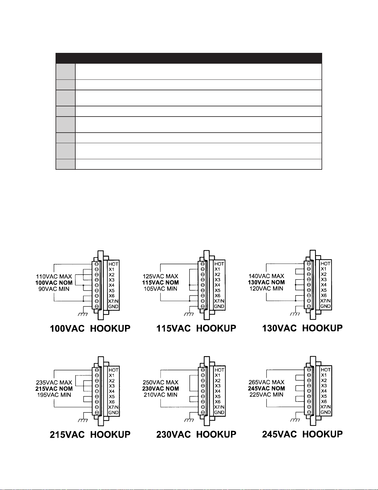
Power Supply Requirements
The DPA10002-01, DPG10003-01 and DPG10004-01 are all powered by an AC line voltage ranging from
90-265VAC. The following figure shows the various line voltages.
December 2004
Page 4
Absolute Maximum Ratings
Input Voltage: 90-265 VAC
Output Current: 10.0 AMPS PEAK
Max Plate Temperature: 70° C
Storage Temperature: 0° to +50° C
Input Voltage (For isolated inputs): +5V to +24V at 2.5mA
Electrical Specifications
metI niM pyT xaM stinU
egatloVtupnI 09562CAV
tnerruCtuptuOesahP 0.11.7)SMR(A
tnerruCtuptuOesahP 5.10.01)KAEP(A
ycneuqerFkcolC 0004zHk
ycneuqerFgnippohC 027233zHk
CDV5+ 8.452.5V
CDV5+ 005Am
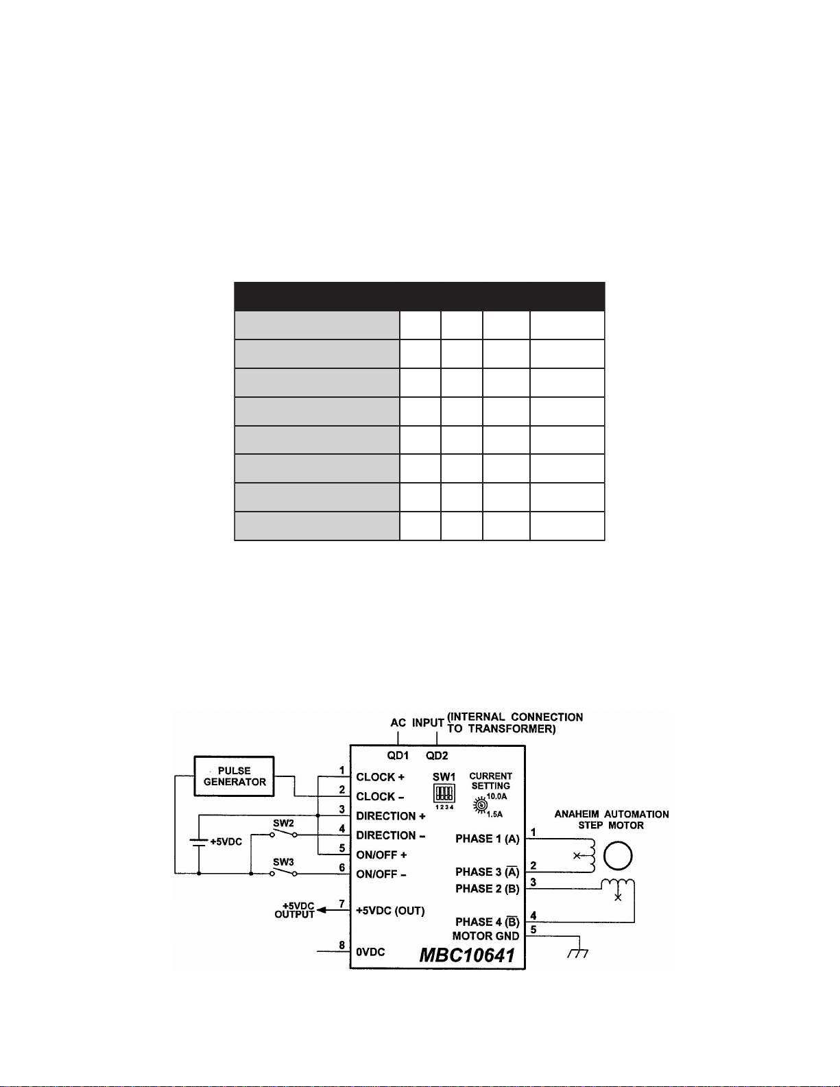
Hook Up Drawings
Hook Up for Current Sinking Inputs
erutarepmeTnoitarepO 007C
Optional: Non-Isolated +5VDC Output can power the MBC10641 Inputs (but isolation is eliminated).
User’s Guide # L010167
Page 5
DB25 PIN Port Connection Description
1. No Connection 14. Enable All Windings
2. No Connection 15. No Connection
3. No Connection 16. No Connection
4. No Connection 17. No Connection
5. No Connection 18. No Connection
6. No Connection 19. A Direction Input
7. No Connection 20. Z Direction Input
8 No Conneciton 21. Y Direction Input
9. X Direction 22. +5VDC Input Required to Power Driver OPTO
10. A Step ( Clock Input) 23. +5VDC Input Required to Power Driver OPTO
11. Z Step ( Clock Input) 24. No Connection
12. Y Step ( Clock Input) 25. No Connection
13. X Step ( Clock Input)
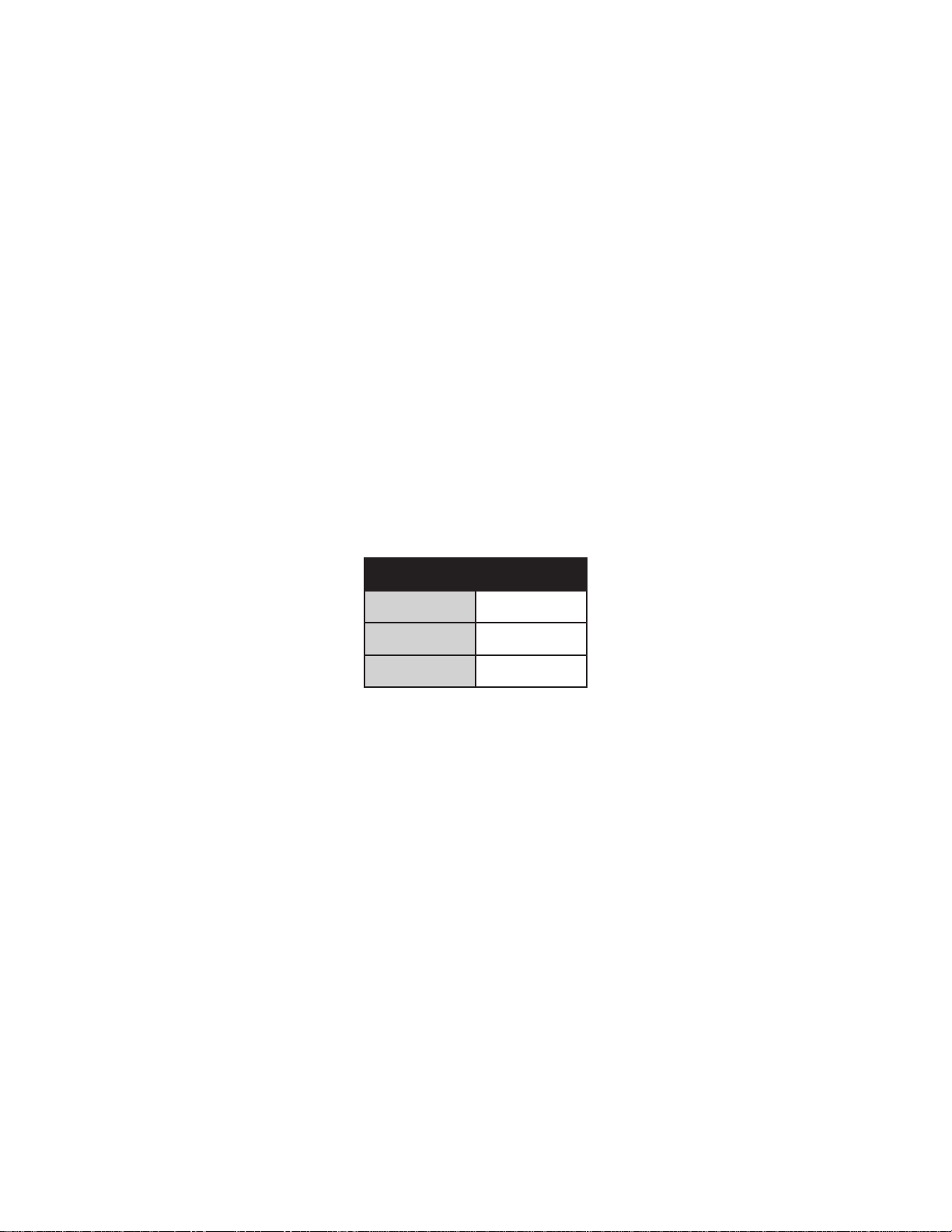
Optically Isolated Inputs
The following inputs to the MBC10641 are Optically Isolated.
metI #niP
kcolC2&1
noitceriD4&3
ffO/nO6&5
To enable an input, apply a DC voltage source of +5VDC to +24VDC across the inputs. The Anodes (+)
are pins 1,3,and 5 and the Cathodes (-) are pins 2, 4, and 6.
Motor Selection
The MBC10641 is a Bipolar Microstep Driver that is compatible with both Bipolar and Unipolar Motor
Configurations, (i.e. 8 and 4 lead motors, and 6 lead center tapped motors).
Step motors with low current ratings and high inductance will perform better at low speeds, providing
higher low-end torque. Motors with high current ratings and low inductance will perform better at higher
speeds, providing more high-end torque.
Since the MBC10641 is a constant current source, it is not necessary to use a motor that is rated at the
same voltage as the supply voltage. What is important is that the MBC08161 is set to the appropriate
current level based on the motor being used. Higher voltages will cause the current to flow faster through
the motor coils. This in turn means higher step rates can be achieved.
the maximum voltage of the driver.
Care should be taken not to exceed
Anaheim Automation offers a comprehensive line of step motors in 17, 23, 34 and 42 frame
sizes. Contact the factory to verify motor/ drive compatibility
.
December 2004
Page 6
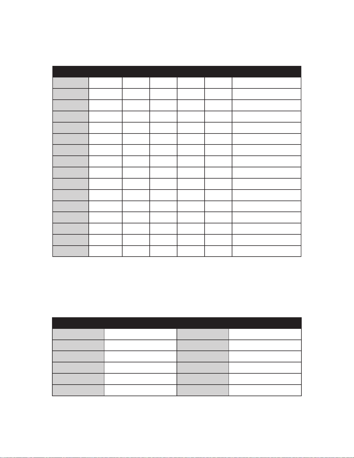
Microstep Selection (SW1 Settings)
Switches 2, 3 and 4, of the DIP switch select the number of microsteps per step. Table 7 shows the
standard resolution values along with the associated positions for the select switches. The standard waveforms are sinusoidal.
noituloseR veR/spetS 1tceleS 2tceleS 3tceleS 4tceleS tnerruCecudeRotuA
1
2
5
8
01
61
23
46
1
2
5
8
01
61
23
002FFONONONOdelbasiD
004FFONONOFFOdelbasiD
0001FFONOFFONOdelbasiD
0061FFONOFFOFFOdelbasiD
0002FFOFFONONOdelbasiD
0023FFOFFONOFFOdelbasiD
0046FFOFFOFFONOdelbasiD
00821FFOFFOFFOFFOdelbasiD
002NONONONOdelbanE
004NONONOFFOdelbanE
0001NONOFFONOdelbanE
0061NONOFFOFFOdelbanE
0002NOFFONONOdelbanE
0023NOFFONOFFOdelbanE
0046NOFFOFFONOdelbanE
46
00821NOFFOFFOFFOdelbanE
Table 6: Microstep Selection on Switch 1.
Setting the Output Current
The output current on the MBC10641 is set by an onboard potentiometer. This potentiometer determines
the per phase peak output current of the driver. The relationship between the output current and the
potentiometer value is as follows:
tnerruCkaeP gnitteSretemoitnetoP tnerruCkaeP gnitteSretemoitnetoP
A5.1%0 A0.7%06
A3.2%01 A9.7%07
A1.3%02 A7.8%08
A0.4%03 A6.9%09
A0.5%04 A01%001
A0.6%05 ----
Table 7: Potentiometer values with respect to the output current
Refer to Table 5 for specific motor current settings.
User’s Guide # L010167
Page 7
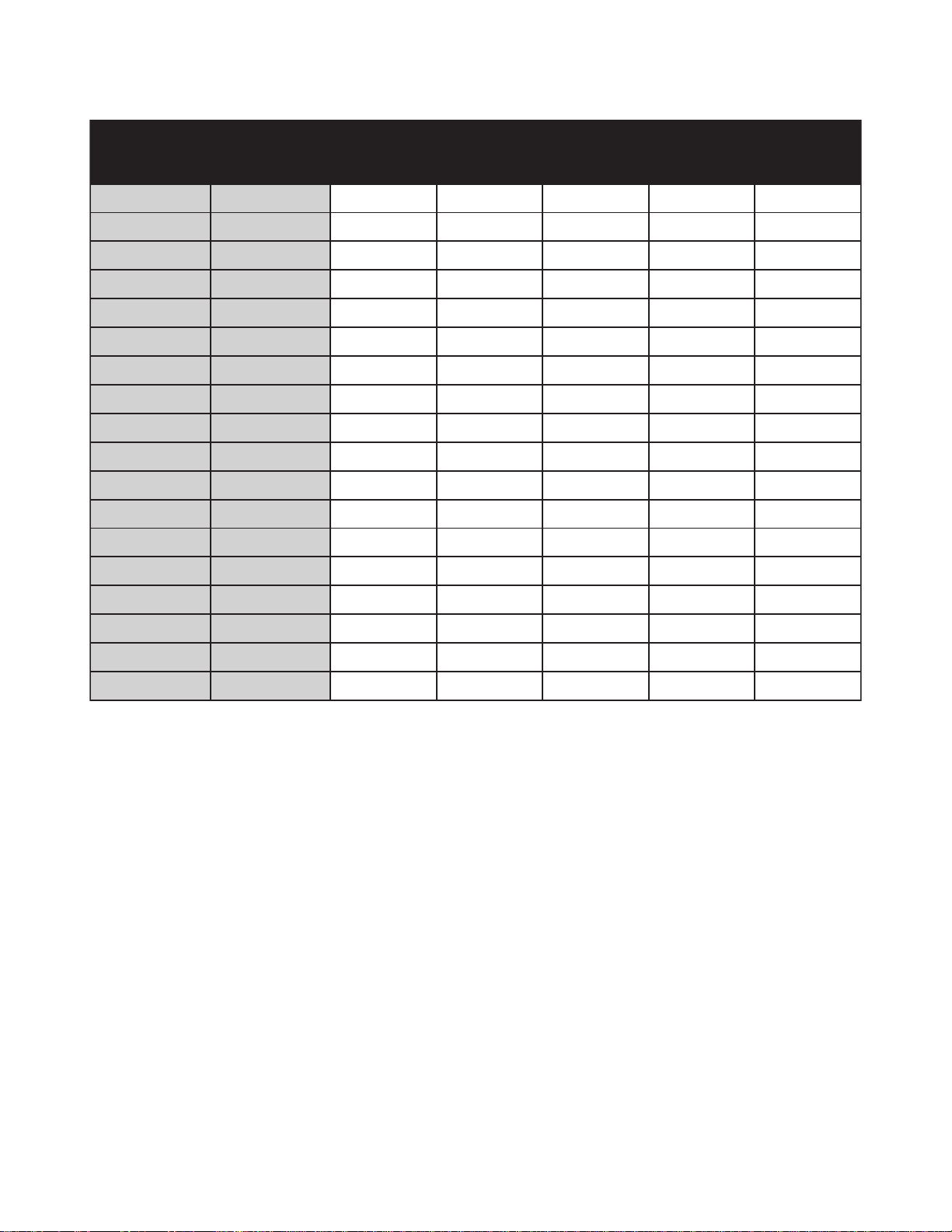
Step Motor Selection Guide
elpmaxErotoM
1D3220S 20
3L32308WL-D 30
1N43408WL-S 40
04L32508WL-D 50
1A4360B 60
2N43708WL-S 70
1K43808WL-S 80
2N2490BC-S 90
3L32018WL-S 01
3D4311D 11
1K2421BC-S 21
2D4331S 31
3N43418WL-S 41
1N2451BC-D 51
tnerruCrotoM
edoCrebmuN
ralopinU
gnitaR
A0.1A0.1A0.2----%5
A5.1A5.1A0.3%0%02
A0.2A0.2A0.4%5%03
A5.2A5.2A0.5%01%04
A0.3A0.3A0.6%02%05
A5.3A5.3A0.7%52%06
A0.4A0.4A0.8%03%07
A5.4A5.4A0.9%53%58
A0.5A0.5A0.01%04%001
A5.5A5.5A0.11%54%001
A0.6A0.6A0.21%05%001
A5.6A5.6A0.31%55%001
A0.7A0.7A0.41%06%001
A5.7A5.7A0.51%56----
kaePseireS
gnitaR
kaePlellaraP
gnitaR
seireS
tnerruC
gnitteS
lellaraP
tnerruC
gnitteS
4K43618WL-S 61
1D2491D 91
3N2422BC-S 22
2D2452S 52
TABLE 5 - Table Selection for Anaheim Automation Motor Current Settings.
A0.8A0.8A0.61%07---A5.9A5.9A0.91%09----
A0.11A0.11A0.22%001---A5.21A5.21A0.52%001----
Anaheim Automation offers motor cable, making hook-ups quick and easy!
Contact the factory or visit our website for more motor and cable offerings.
Reducing Output Current
Reducing the output current is accomplished by setting switch 1 of the DIP switch to the ON position and
occurs approximately 1 second after the last positive going edge of the step clock input. The amount of
current per phase in the reduction mode is approximately 70% of the set current. When the current
reduction circuit is activated, the current reduction resistor is paralleled with the current adjustment poten-
tiometer. This lowers the total resistance value, and thus lowers the per Phase output current.
Determining Output Current
The output current for the motor used when microstepping is determined differently from that of a full/half
step unipolar driver. In the MBC08161, a sine/cosine output function is used in rotating the motor. The
output current for a given motor is determined by the motors current rating and the wiring configuration of
the motor. There is a current adjustment potentiometer used to set the output current of the MBC10641.
This sets the peak output current of the sine/cosine waves. The specified motor current (which is the
unipolar value) is multiplied by a factor of 1.0, 1.4, or 2.0 depending on the motor configuration (series,
half-coil, or parallel).
December 2004
Page 8
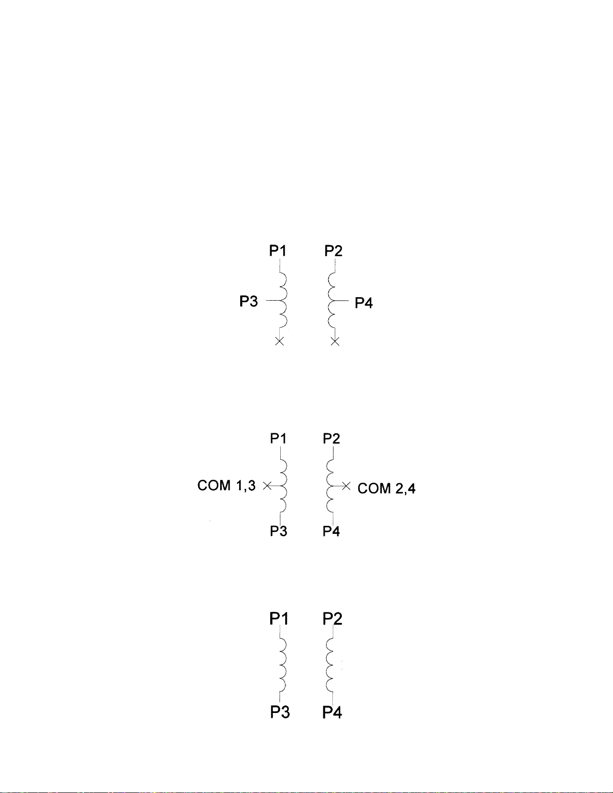
Step Motor Configurations
Step motors can be configured as 4, 6, or 8 leads. Each configuration requires different currents. Refer to
the lead configurations and the procedures to determine their output current.
WARNING! Step motors will run hot even when configured correctly. Damage may occur to the motor if a
higher than specified current is used. Most specified motor currents are maximum values. Care should be
taken to not exceed these ratings.
6 Lead Motors
When configuring a 6 lead motor in a
center tap), multiply the specified per Phase (or unipolar) current rating by 1.4 to determine the current
setting potentiometer value. This configuration will provide more torque at higher speeds when compared
to the series configuration.
half-coil configuration
(connected from one end of the coil to the
When configuring the motor in a
series configuration
(connected from end to end with the
center tap floating) use the specified per Phase (or unipolar) current rating to determine the
current setting potentiometer value.
4 Lead Motors
Multiply the specified
value. Four Lead Motors are usually rated with their appropriate series current, as opposed to the
Current
, which is the rating for 6 and 8 lead motors.
series
motor current by 1.4 to determine the current adjustment potentiometer
Phase
User’s Guide # L010167
Page 9
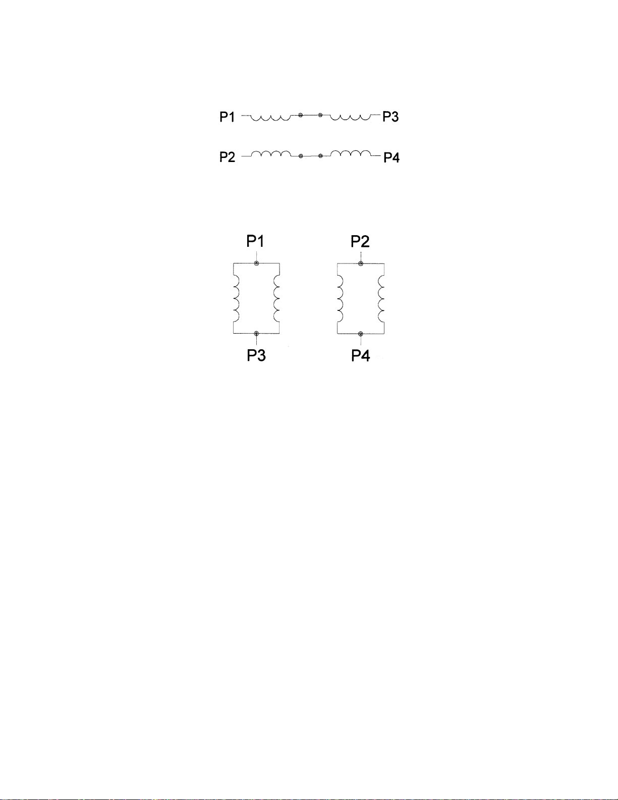
8 Lead Motors
Series Connection: When configuring the motor windings in series, use the per Phase (or unipolar)
current rating to determine the current setting potentiometer value.
Parallel Connection: When configuring the motor windings in parallel, multiply the per Phase (or unipolar) current rating by 2.0 to determine the current setting potentiometer value.
NOTE: After the current has been determined, according to the motor connections above, use Table 3 to
choose the proper setting for the current setting potentiometer.
Connecting the Step Motor
Phase 1 and 3 of the Step Motor is connected between pins 1 and 2 on the motor connector (TB2). Phase
2 and 4 of the Step Motor is connected between pins 3 and 4 on the motor connector (TB2). The motors
case can be grounded to pin 5 on the motor connector (TB2). Refer to the figures for the hook-up drawings
for TYPICAL APPLICATION HOOK-UPS.
NOTE: The physical direction of the motor with respect to the direction input will depend on the connection
of the motor windings. To reverse the direction of the motor with respect to the direction input, switch the
wires on Phase 1 and Phase 3.
WARNING: Do not connect or disconnect motor wires while power is applied!
Short-Circuit, Mis-Wire, and Over-Current Conditions
If it is found that there is a condition that causes on over current in the driver phase transistors, the Red
LED will turn on solid and power will be shut off to the motor. To reset the drive turn power off, check
0wiring, and turn power back on.
Over-Temperature and Over-Voltage Conditions
If it is found that there is an over temperature on the internal heat sink, or an over voltage on the motor bus
voltage, the Red LED will blink and power will be shut off to the motor. To reset the drive turn power off,
check wiring, and turn power back on.
December 2004
Page 10
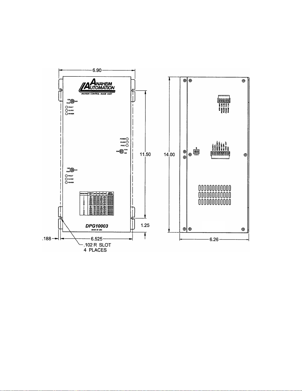
Dimension Drawings
DPG10002-01, DPG10003-01 and DPG10004-01 Micostep Driver Pack
User’s Guide # L010167
Page 11

COPYRIGHT
Copyright 2001 by Anaheim Automation. All rights reserved. No part of this publication may be reproduced, transmitted, transcribed, stored in a retrieval system, or
translated into any language, in any form or by any means, electronic, mechanical, magnetic, optical, chemical, manual, or otherwise, without the prior written
permission of Anaheim Automation, 910 E. Orangefair Lane, Anaheim, CA 92801.
DISCLAIMER
Though every effort has been made to supply complete and accurate information in this manual, the contents are subject to change without notice or obligation to inform
the buyer. In no event will Anaheim Automation be liable for direct, indirect, special, incidental, or consequential damages arising out of the use or inability
to use the product or documentation.
Anaheim Automation’s general policy does not recommend the use of its’ products in life support applications wherein a failure or malfunction of the product may directly
threaten life or injury. Per Anaheim Automation’s Terms and Conditions, the user of Anaheim Automation products in life support applications assumes all risks of such
use and indemnifies Anaheim Automation against all damages.
LIMITED WARRANTY
All Anaheim Automation products are warranted against defects in workmanship, materials and construction, when used under Normal Operating Conditions and when
used in accordance with specifications. This warranty shall be in effect for a period of twelve months from the date of purchase or eighteen months from the date of
manufacture, whichever comes first. Warranty provisions may be voided if products are subjected to physical modifications, damage, abuse, or misuse.
Anaheim Automation will repair or replace at its’ option, any product which has been found to be defective and is within the warranty period, provided that the item is
shipped freight prepaid, with previous authorization (RMA#) to Anaheim Automation’s plant in Anaheim, California.
TECHNICAL SUPPORT
If you should require technical support or if you have problems using any of the equipment covered by this manual, please read the manual completely to see if it will
answer the questions you have. Be sure to refer to the TROUBLESHOOTING section of this manual. If you need assistance beyond what this manual can provide,
contact your Local Distributor where you purchased the unit, or contact the factory direct.
December 2004
Page 12
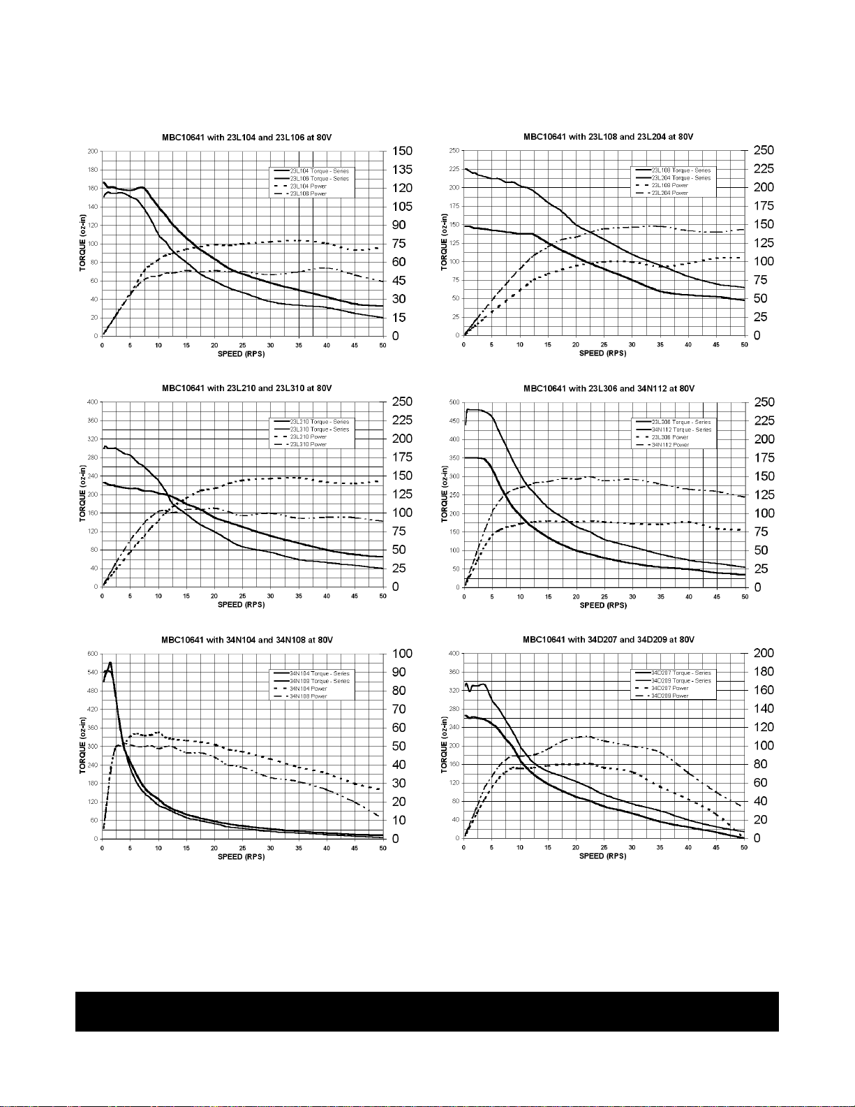
Torque Speed Curves
ANAHEIM AUTOMATION
User’s Guide # L010167
 Loading...