

AMX VTX Instruction Manual

t a k e c o n t r o l
VTX Video Teleconferencing System
Instruction Manual PRELIMINARY

Limited Warranty and Disclaimer
AMX Corporation warrants its products to be free from defects in material and
workmanship under normal use for a period of three years from date of purchase
from AMX, with the following exceptions. Electroluminescent and LCD control
panels are warranted for a period of three years, except for the display and touch
overlay components which are warranted for a period of one year. Disk drive
mechanisms, pan/tilt heads, codecs, power supplies, modifications, MX Series
products, and KC Series products are warranted for a period of one year. Unless
otherwise specified, OEM and custom products are covered for a period of one year.
AMX software products are warranted for a period of 90 days. Batteries and
incandescent lamps are not covered.
This warranty extends to products purchased directly from AMX or an authorized
AMX dealer. Consumers should inquire from selling dealer as to the nature and
extent of the dealer’s warranty, if any.
AMX is not liable for any damages caused by its products or for the failure of its
products to perform, including any lost profits, lost savings, incidental damages, or
consequential damages. AMX is not liable for any claim made by a third party or
made by you for a third party.
This limitation of liability applies whether damages are sought, or a claim is made,
under this warranty or as a tort claim (including negligence and strict product
liability), a contract claim, or any other claim. This limitation of liability cannot be
waived or amended by any person. This limitation of liability will be effective even if
AMX or an authorized representative of AMX has been advised of the possibility of
any such damages. This limitation of liability, however, will not apply to claims for
personal injury.
Some states do not allow a limitation of how long an implied warranty lasts. Some
states do not allow the limitation or exclusion of incidental or consequential damages
for consumer products. In such states, the limitation or exclusion of the Limited
Warranty may not apply to you. This Limited Warranty gives you specific legal
rights. You may also have other rights that may vary from state to state. You are
advised to consult applicable state laws for full determination of your rights.
EXCEPT AS EXPRESSLY SET FORTH IN THIS WARRANTY, AMX MAKES NO OTHER
WARRANTIES, EXPRESSED OR IMPLIED, INCLUDING ANY IMPLIED WARRANTIES OF
MERCHANTABILITY OR FITNESS FOR A PARTICULAR PURPOSE. AMX EXPRESSLY DISCLAIMS
ALL WARRANTIES NOT STATED IN THIS LIMITED WARRANTY. ANY IMPLIED WARRANTIES
THAT MAY BE IMPOSED BY LAW ARE LIMITED TO THE TERMS OF THIS LIMITED WARRANTY.

i
Table of Contents
Introduction .............................................................................1
Overview 1
Features 2
Application 4
What’s in this Manual 4
Pre-Installation........................................................................7
Overview 7
ISDN Information 7
Positioning the TiltCam 8
AXlink Wiring 8
Preparing captive wires 8
Using the mini-XLR connector 9
Wiring AXlink and Power for the TiltCam 9
Audio/video wiring 9
Installation............................................................................ 11
Overview 11
Precautions 11
Installing the VTX System 11
Configuring the VTX 13
Configuring the ISDN lines 13
Configuring video input 17
Recording Speed Dial Numbers 18
VTX Video Teleconferencing System Table of Contents
Operation.............................................................................. 21
Overview 21
TiltCam pages 21
Making a Video Teleconference Call 22
Page Features 25
Speed dial page features 25
Manual dial page features 26
Conference control page features 29
Camera control page features 31

Advanced Configuration ...................................................... 33
Overview 33
Utilities Page 33
Setup Page 36
Setting the date and time 37
Setting the background 38
Setting up the video 38
7Setting up the password 39
Specifications....................................................................... 41
Overview 41
Glossary................................................................................ 45
Overview 45
Terminology 45
Technical Support ................................................................ 49
Overview 49
Appendix A: ISDN Form........................................................ 51
ii Table of Contents VTX Video Teleconferencing
Introduction
Overview
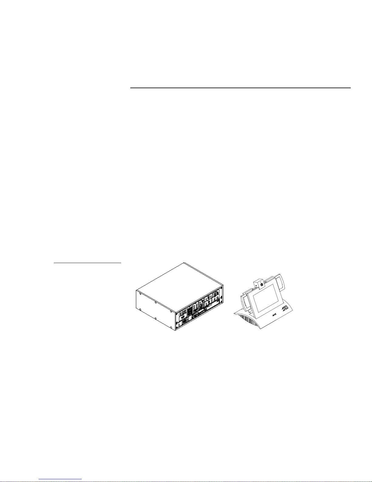
The AMX VTX (Figure 1) is an easy-to-use desktop video teleconferencing system
with options for expansion. The system is pre-programmed for the addition of an
external camera, an external monitor, a VCR, an external microphone, an external
sound system, an external echo canceller, and a mic mixer. A VTX server system can
create a distributed conferencing system, allowing multiple users with desktop
TiltCam touch panels to share a common pool of video teleconferencing equipment.
This manual describes a typical application using a combination of AMX equipment.
The VTX application described in this manual features the following AMX
standalone equipment: the exclusive AMX TiltCam, a color active-matrix LCD
TiltScreen touch panel that integrates graphical touch control with a built-in video
window, color camera, microphone, speakers, the VTX-2 codec, the AXB-EM232
Enhanced Master/RS-232 Controller, and the PS4.2 12 VDC, 4.2 A power supply. All
VTX systems are ready for use, with pre-programmed graphics and control
software. All VTX components are sold separately.
Figure 1
VTX video teleconferencing
system
VTX
TiltCam
The VTX Video Teleconferencing System described in this document includes the
following AMX products:
• AXB-EM232 Enhanced Master/RS-232 Controller, a bus device that functions
like an AMX Enhanced System Master Card in a single compact enclosure and
has VTX-specific AXCESS programming
VTX Video Teleconferencing System - Preliminary Introduction 1

• VTX, a codec that compresses and transmits outgoing video, audio, and data
and receives and decompresses incoming video, audio and data. The VTX-2
features a 128 Kbps codec with a built-in IMUX that can be converted to a
VTX-6, a 384 Kbps codec with three ISDN line operation, with an optional
software upgrade. The VTX-1 accepts a single ISDN feed.
• TiltCam, an active-matrix color TouchPanel with video window equipped
with a high quality color camera, condenser microphone, and compact stereo
speakers.
• PS4.2 12 VDC, 4.2 A, a power supply that provides regulated switching of
110/220 VAC input.
Features
The following are the features of the VTX Video Teleconferencing System
application:
• On-screen status displays
• Single-button speed dialing
• Manual dialing
• Last number redial
• Simple pick-up and hang-up buttons
• Auto answer
• Configurable alerts for incoming telephone or video calls
• Flexible picture in picture modes
• Incoming audio volume control
• Incoming audio mute
• Multiple audio/video send sources (including external microphone)
• Graphics send and receive
• Full-screen video
• Picture-in-picture for incoming and outgoing video
2 Introduction VTX Video Teleconferencing System - Preliminary

• Outgoing audio privacy mode
• Outgoing video privacy mode
• Local camera control
• Far end camera control
• Far end source selects
• Built-in self-adapting, full-duplex, sub-band echo canceller
• Automatic selection of H.261 and H.263 video modes
• Automatic selection of G.711, G.722, and G.728 audio modes
• Data channel for application sharing and easy upgrading of the VTX and
TiltCam software
• Adherence to H.281 far end camera control standards
• Remote control of virtually any camera pan/tilt head
• Remote activation of functions on far end control system (two VTX systems)
• Ability to place telephone and video calls over the same ISDN line
• Ability to use an optional external echo canceller for room-based video
teleconferencing.
VTX Video Teleconferencing System - Preliminary Introduction 3
ECHO CANCELLER
AXlink
DATA
RS-232
AXlink
EXT. MIC
RS232
TX1
RX1
PUSH
2
1ONRS232/422
TX2
RX2
Power Supply
4.2DCPS
12V
S-VIDEO
RECORD
MONITOR
TILTCAM
ISDN 1
ISDN
ISDN 2
AXlink
ISDN 3
CAMERA
S-VIDEO
AUX INPUTS
S-VIDEO
EXTERNAL
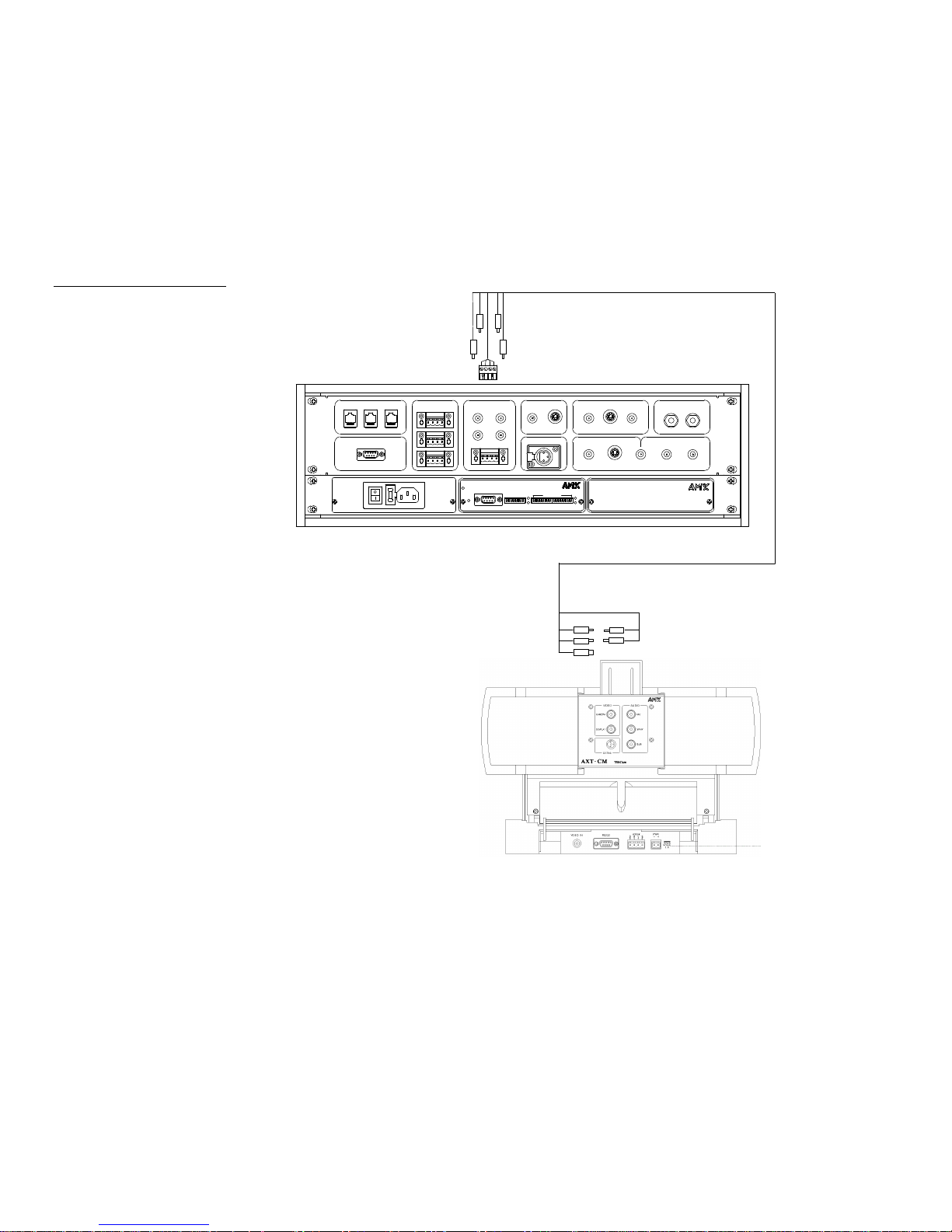
Figure 2
VTX application
Application
Figure 2 shows a video teleconferencing application using the VTX system.
MIC VIDEO
SPKR
CAMERA VIDEO
DISPLAY
PROGRAM
PROGRAM
AUDIO
MIX
AUDIO
MAIN
MAIN
VIDEO
OUTGOING
MIC/RCV
SPKR/SND
INCOMING
AUDIO
VIDEO
What’s in this Manual
This manual comprises the following sections:
• Pre-Installation Describes the configuration of the VTX system.
• Installation Describes the installation of the VTX system.
4 Introduction VTX Video Teleconferencing System - Preliminary

• Operation Describes the basic operations of the VTX system.
• Specifications Describes the specifications for the TiltCam and the VTX.
• Glossary Lists terminology used in Video Teleconferencing.
• Appendix A Give areas to record ISDN information.
• Technical Support Lists the telephone numbers to call for AMX technical
support.
For additional information about the AXB-EM232, refer to the AXB-EM2322
Enhanced Master RS-232 Controller, 032-0004-1013. For additional information
about the touch panel features of the TiltCam, refer to the Color Active-Matrix
LCD Touch Panel Instruction Manual, 036-004-1387.
VTX Video Teleconferencing System - Preliminary Introduction 5

6 Introduction VTX Video Teleconferencing System - Preliminary

Pre-Installation
the inside wiring.
Overview
The section describes the configuration required prior to installing the VTX system.
You will need to:
• Obtain and record the specific ISDN information
• Properly position the TiltCam for use
• Prepare the AXlink wires, if you are manufacturing the cables
• Wire the system for AXlink and power
ISDN Information
When you call and request service, obtain the information from the telephone
company Central Office (CO) about the Integrated System Digital Network (ISDN).
Record the information on the form in Appendix A: ISDN Form. Obtain and record all
the information listed in the form. It will assist in identifying the ISDN line, should
you ever need to contact the CO about the service.
To record all the ISDN information:
1. Record the work order information, the cost information, and the ISDN
information.
2. Enter the ISDN line information. For each ISDN Billing Rate Identification (BRI)
line, there will be two numbers, the telephone number and the Service Profile
Note
We recommend that you have
the service provider perform all
Identification (SPID).
3. Enter the service provider’s information.
4. Enter the Circuit IDs for the D channel and the B channel. The representative
will not know this ID; they must obtain it from the engineering group. Have
them get you that information.
5. Enter the service provider’s Preferred Interexchange Carrier (PIC) code.
6. Enter the their repair telephone number.
VTX Video Teleconferencing System - Preliminary Pre-Installation 7

7. Enter their technical support telephone number.
8. Ask the representative to fax you a completed copy of their work order.
9. Make more than one photocopy of the completed form to post near the NT 1 box
and near the VTX.
Positioning the TiltCam
Place the TiltCam on a stable surface. Keep the following guidelines in mind when
you are positioning the TiltCam:
• Colored lighting, direct lighting on the caller and the TiltCam, harsh overhead
(spot-type) lighting, and extremely low-level lighting produce overly harsh
illumination, too much shadow, or insufficient lighting for video
teleconferencing.
• Indirect light from shaded sources, natural light, and light reflected off of
light-colored walls provides excellent illumination for video teleconferencing.
• Heavy patterned or brightly colored backgrounds (behind the caller) may
adversely tint the picture.
• Moving backgrounds (people or objects) may distract the attention of the
party receiving the call.
AXlink Wiring
The AXlink cable required for this VTX application must have an 4-pin XLR
connector on the TiltCam side and a 4-pin captive-wire connector on the VTX side. If
you are manufacturing the cable, you must properly prepare the captive wires, as
described in the following section.
Preparing captive wires
To connect the wiring into a captive-wire connector, follow these steps.
Caution
Do not over-torque the screw.
Doing so can bend the seating
pin and damage the connector.
1. Strip 0.25 inch off the wire insulation for all four wires.
2. Tin 2/3 of the exposed wire.
3. Insert each wire into the appropriate opening on the connectors on the back of
the VTX according to Figure 3. Insert the wire up to the insulation.
4. Turn the captive screws clockwise to secure the fit in the connector.
8 Pre-Installation VTX Video Teleconferencing System - Preliminary
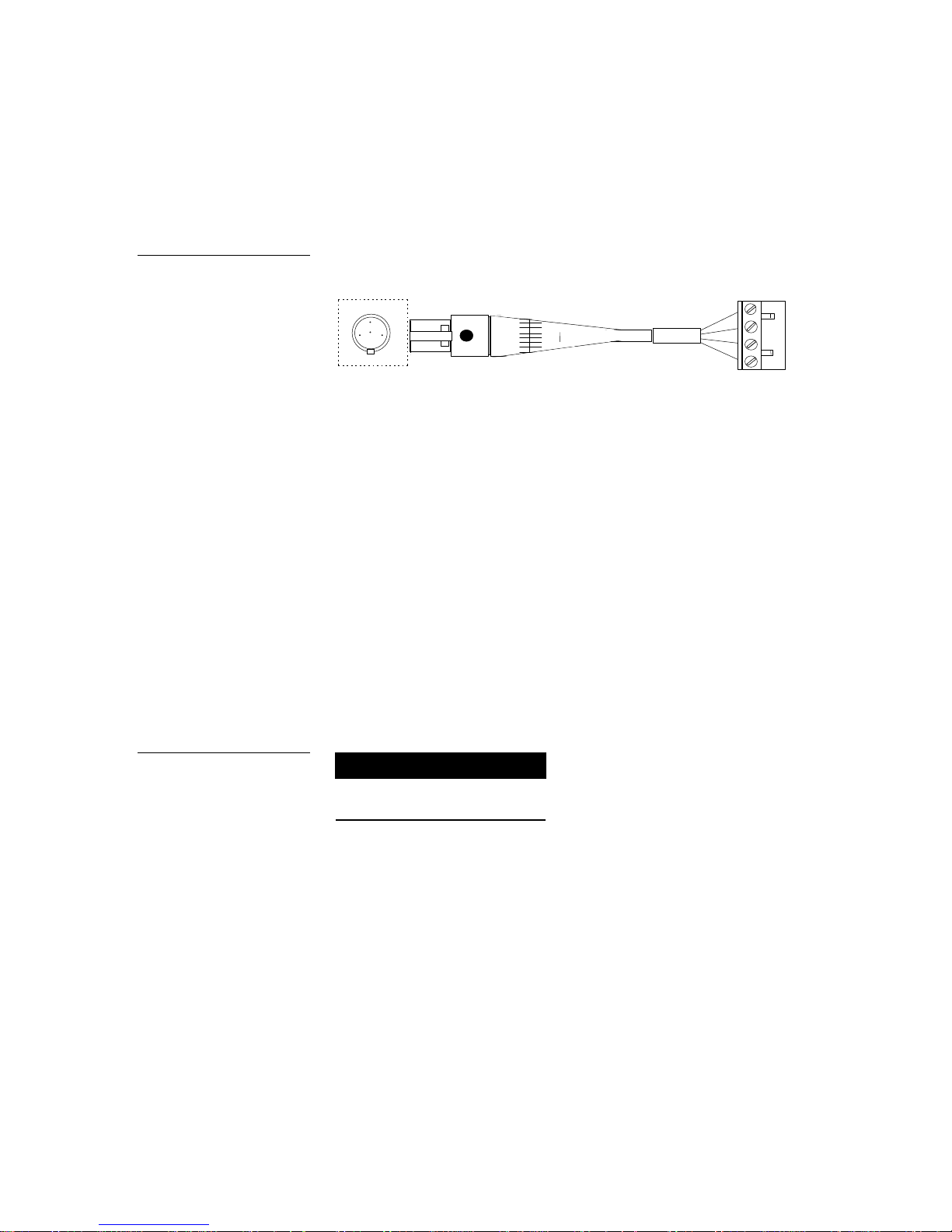
Using the mini-XLR connector
GND - (BLK)
2
1
PWR + (RED)
AXM (GRN)
AXP (WHT)
3
412
3
4
1 - GND - (BLK)
3 - AXP (WHT)
2 - AXM (GRN)
4 - PWR + (RED)
connector
connector
Connect the AXlink wiring in the mini-XLR connector as shown in Figure 3.
Figure 3
AXlink wiring
4-pin XLR
4-pin captive-wire
Wiring AXlink and Power for the TiltCam
The TiltCam requires 12 VDC power to operate properly. The power is supplied by
the AMX system’s AXlink cable. The maximum AXlink wiring distance between
control system (in this application, the VTX, which is obtaining power from the
AXB-EM232) and the TiltCam is determined by power consumption, supplied
voltage, cable compliance, and the wire gauge used for the cable. If you are
manufacturing your cable, refer to Figure 4, which lists wire sizes and the maximum
lengths allowable between the receiver or sensor and the control system. The
maximum wiring lengths are based on a minimum of 13.5 volts available at the
central controller’s (AXB-EM232) power supply.
Figure 4
Wiring guidelines
Wiring guidelines
Maximum wiring
Wire size
20 AWG 148 feet
22 AWG 92 feet
24 AWG 58 feet
length
Audio/video wiring
The TiltCam’s microphone and speaker wiring are unbalanced, line level signals. As
with any unbalanced line level audio wiring, if the TiltCam is located more than 25
feet from the VTX, it may be necessary to install buffer amplifiers between the
TiltCam and the VTX or routing switcher, or convert the signals for operation over
unshielded twisted pair (UTP) cable.
VTX Video Teleconferencing System - Preliminary Pre-Installation 9

10 Pre-Installation VTX Video Teleconferencing System - Preliminary

Installation
Overview
This section describes the procedures for installing and configuring the VTX system.
Precautions
Please note the following precautions:
• Do not install telephone wiring during a lightning storm.
• Do not install telephone connectors in wet locations unless the connector is
specifically designed for wet locations.
• Do not touch telephone wires or terminals unless the telephone line has been
disconnected at the network interface.
• Use caution when installing or modifying telephone lines.
• Avoid using a telephone (other than the cordless type) during an electrical
storm.
• Switch the power off before installing any of the cables.
Installing the VTX System
To install the VTX system:
1. Connect the power cable to the AC connector on the back of the VTX and plug
the cable into the grounded outlet.
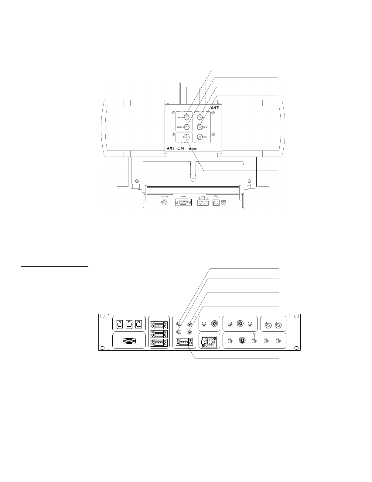
2. Connect the RCA cable connectors to the TiltCam (Figure 5).
3. Connect the cables from the TiltCam to the VTX (Figure 5 and Figure 6).
VTX Video Teleconferencing System - Preliminary Installation 11
CAMERA
AXlink
P
U
S
H
CAMERA
DISPLAY
SPKR
MIC
Figure 5
TiltCam connectors
DISPLAY
MIC
SPKR
Figure 6
VTX connectors
ISDN
ISDN 2
ISDN 1 ISDN 3
DATA
RS-232
AXlink
SPKR
MIC
TILTCAM
AXlink
CAMERA
DISPLAY
VIDEO
CAMERA
EXT. MIC
S-VIDEO
VIDEO
AUDIO
MIX
AUX INPUTS
S-VIDEO AUDIO
RECORD
MAIN
S-VIDEO
EXTERNAL
ECHO CANCELLER
SPKR/SND MIC/RCV
MONITOR
MAIN
OUTGOING
VIDEO
INCOMING
VIDEO
AUDIO
AXlink
12 Installation VTX Video Teleconferencing System - Preliminary

4. Turn on the power switch located next to the AC connector on the back of the
NT 1 interface manufacturer.
VTX. The AXlink and TX/RX LEDs on the AXB-EM232 will blink, the panel will
beep, and the codec will go through self-test.
5. Connect the ISDN line (or lines) to the VTX via the NT 1.
Note
If you are not using the
EC NT1 , follow the
instructions provided by the
Figure 7
AMX title page
a. Connect the power supply to the NT 1, and plug the power supply in.
The power LED is on and the ST&U LED blinks a few times then lights
continuously.
b. Connect the ISDN line to the U-connector on the NT 1.
The ST&U LED blinks rapidly several times, then blinks once per second,
indicating that the U link has been established.
6. Connect RJ-45 cable from ISDN connector on system to S/T connector on
NT 1. The ST&U LED goes out, indicating that a link has been established
between the S/T and U interfaces.
Configuring the VTX
The first page that displays on the TiltCam is the AMX title page (Figure 7).
VTX Video Teleconferencing System - Preliminary Installation 13
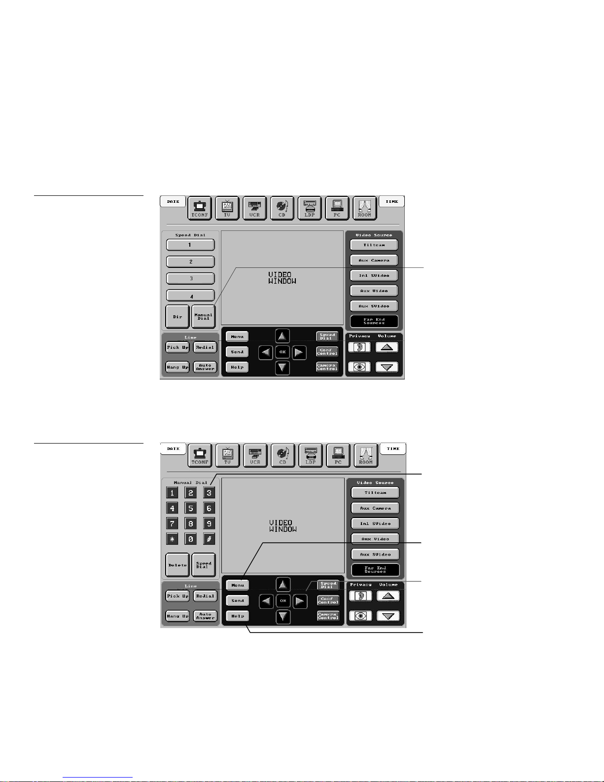
Figure 8
Speed dial page
Configuring the ISDN lines
To configure the ISDN line or lines:
1. Press the center area of title page to flip to the speed dial page (Figure 8).
Manual dial button
Figure 9
Numeric buttons, Menu button,
and direction arrow buttons on
the manual dial page
2. Press the Manual Dial button to flip to the manual dial page (Figure 9).
Numeric buttons
MENU button
Directional arrow buttons
HELP button
14 Installation VTX Video Teleconferencing System - Preliminary
 Loading...