

Page 1

Operation/Reference Guide
ViewStat
Communicating Thermostat
Product Category
Last Revised: 5/16/2008
Page 2

AMX Limited Warranty and Disclaimer
AMX Corporation warrants its products to be free of defects in material and workmanship under normal use for
three (3) years from the date of purchase from AMX Corporation, with the following exceptions:
• Electroluminescent and LCD Control Panels are warranted for three (3) years, except for the display and touch overlay components that are warranted for a period of one (1) year.
• Disk drive mechanisms, pan/tilt heads, power supplies, MX Series products, and KC Series products are
warranted for a period of one (1) year.
• Unless otherwise specified, OEM and custom products are warranted for a period of one (1) year.
• Software is warranted for a period of ninety (90) days.
• Batteries and incandescent lamps are not covered under the warranty.
This warranty extends only to products purchased directly from AMX Corporation or an Authorized AMX Dealer.
AMX Corporation is not liable for any damages caused by its products or for the failure of its products to perform. This includes any
lost profits, lost savings, incidental damages, or consequential damages. AMX Corporation is not liable for any claim made by a third
party or by an AMX Dealer for a third party.
This limitation of liability applies whether damages are sought, or a claim is made, under this warranty or as a tort claim (including
negligence and strict product liability), a contract claim, or any other claim. This limitation of
liability cannot be waived or amended by any person. This limitation of liability will be effective even if AMX
Corporation or an authorized representative of AMX Corporation has been advised of the possibility of any such damages. This limitation of liability, however, will not apply to claims for personal injury.
Some states do not allow a limitation of how long an implied warranty last. Some states do not allow the limitation or exclusion of incidental or consequential damages for consumer products. In such states, the limitation or exclusion of the Limited Warranty may not
apply. This Limited Warranty gives the owner specific legal rights. The owner may also have other rights that vary from state to state.
The owner is advised to consult applicable state laws for full
determination of rights.
EXCEPT AS EXPRESSLY SET FORTH IN THIS WARRANTY, AMX CORPORATION MAKES NO
OTHER WARRANTIES, EXPRESSED OR IMPLIED, INCLUDING ANY IMPLIED WARRANTIES OF
MERCHANTABILITY OR FITNESS FOR A PARTICULAR PURPOSE. AMX CORPORATION
EXPRESSLY DISCLAIMS ALL WARRANTIES NOT STATED IN THIS LIMITED WARRANTY. ANY
IMPLIED WARRANTIES THAT MAY BE IMPOSED BY LAW ARE LIMITED TO THE TERMS OF THIS
LIMITED WARRANTY.
Page 3

Table of Contents
V
Table of Contents
Product Information ...........................................................................................1
Introduction .............................................................................................................. 1
System Components ................................................................................................. 2
ViewStat Specifications............................................................................................. 2
Support Module Specifications ................................................................................ 3
Maximum Cable Distances ....................................................................................... 4
HVAC System Pre-Installation Check List .................................................................. 5
ViewStat Installation and Wiring ........................................................................7
Disconnecting Power to All HVAC Equipment.......................................................... 7
Selecting the Thermostat Location ........................................................................... 7
Stand-alone thermostat mounting criteria ...................................................................... 7
With remote temperature sensors .................................................................................. 7
Removing the Faceplate from the Base .................................................................... 8
Setting the DIP Switch .............................................................................................. 9
Reassembly ..................................................................................................................... 9
Attaching the MiniVerter to the ViewStat .............................................................. 10
Wiring the VST-TSTAT to a VST-DIST Distribution Panel ........................................ 11
Mounting the Base to a Wall .................................................................................. 12
Connecting the ViewStat to AMX Control Systems ................................................ 13
Connecting to an Axcess Control System (via AXC-232++, AXB-EM232,
or Axcent3/PRO) ........................................................................................................ 14
Connecting to an Axcess Master Controller via the RS232/422/485 (DB-9) Port.......... 15
Connecting to NetLinx Integrated Controllers via the RS232/422/485 (DB-9) Port...... 16
Connecting to a NetLinx Master controller via NXC-COM card.................................... 17
Connecting to a LandMark Control System................................................................... 18
Installing the Cat5 Suppression Ferrite ......................................................................... 18
Connecting to a NetLinx Control System...................................................................... 18
Connecting to a Landmark Control System................................................................... 19
Connecting the ViewStat to the HVAC System....................................................... 19
Installing the 24 VAC Suppression Ferrite..................................................................... 19
Wiring the Thermostat ........................................................................................... 20
Communication and Equipment terminal wiring definitions.......................................... 20
Connecting the ViewStat to the HVAC System............................................................. 21
Checking HVAC System Operation......................................................................... 23
Check Out Procedure.................................................................................................... 23
Optional HVAC Set-Up Features............................................................................. 24
To access these HVAC set-up features.......................................................................... 24
iewStat Communicating Thermostat
i
Page 4

Table of Contents
Address the Thermostats and Set Highest Address................................................ 24
Wiring Diagrams ..................................................................................................... 26
Single-stage furnace and AC configuration. .................................................................. 26
Two-stage furnace and two-stage AC configuration. .................................................... 27
Roof top unit (two-stage heat and two-stage cool) configuration................................. 28
Boiler with AC (two transformers) configuration........................................................... 29
Single-stage heat pump configuration .......................................................................... 30
Two-stage heat pump configuration. ............................................................................ 31
First- stage radiant floor heat, second-stage furnace one stage
of cooling configuration. ............................................................................................ 32
Support Module Installation and Wiring ...........................................................33
Installing the VST-TTM and VST-TRH Support Modules .......................................... 33
Choosing a mounting location....................................................................................... 33
Single Support Module Installation ............................................................................... 33
Multiple Support Module Installation............................................................................ 34
Setting the Support Module DIP Switches.............................................................. 35
DIP switches 1 and 2: Address (1-4) .............................................................................. 36
DIP switch 3: Temperature Sensor 1 ............................................................................. 36
Dip switch 4: Temperature Sensor 2 (VST-TTM support module only) .......................... 36
Dip switch 4: Humidity Sensor 2 (VST-TRH support module only)................................. 36
DIP switch 6: T1/T2 or Onboard Sensor ........................................................................ 36
Applications ............................................................................................................ 37
Heat Pump Applications................................................................................................ 37
Humidity Control (VST-TRH only) .................................................................................. 37
Troubleshooting Remote Sensors ........................................................................... 38
Set Up and Configuration .................................................................................39
Network Override Set-Up ....................................................................................... 40
Thermostat Button Lockout .................................................................................... 40
Security Set-Up ....................................................................................................... 41
Communications Set-Up.......................................................................................... 42
Temperature Set-Up ............................................................................................... 42
Backlighting Set-Up ................................................................................................ 42
Balance Point Set-Up .............................................................................................. 43
Display Set-Up ........................................................................................................ 43
Using the NetLinx Module to Program the ViewStat .......................................45
AMX_ViewStat NetLinx Module - Overview ........................................................... 45
The ViewStat Model ............................................................................................... 46
Command Interface - SEND_COMMANDs .............................................................. 47
String Feedback...................................................................................................... 52
ii
ViewStat Communicating Thermostat
Page 5

Table of Contents
V
Operating the Thermostat ................................................................................57
Front Panel Components ........................................................................................ 57
Message Display ........................................................................................................... 57
Scroll/Set-up buttons .................................................................................................... 57
Mode button................................................................................................................. 57
Adjust buttons............................................................................................................... 57
Fan button..................................................................................................................... 58
Enter button.................................................................................................................. 58
Main display .................................................................................................................. 58
Operating The Thermostat ..................................................................................... 59
Selecting the Mode....................................................................................................... 59
Setting temperatures .................................................................................................... 60
Fan operation................................................................................................................ 60
Backlight operation....................................................................................................... 60
Network override.......................................................................................................... 60
Clearing a temporary flashing message ........................................................................ 60
In Case Of Power Failure ........................................................................................ 60
Cleaning the Thermostat ........................................................................................ 60
iewStat Communicating Thermostat
iii
Page 6

Table of Contents
iv
ViewStat Communicating Thermostat
Page 7
Product Information
Introduction
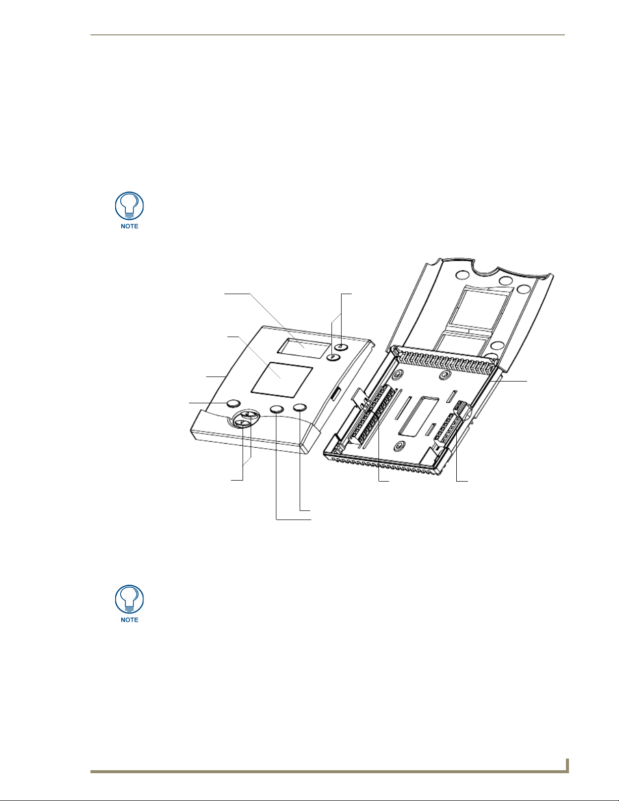
The ViewStat Communicating Thermostat (FIG. 1) operates similarly to a conventional thermostat but has the
unique capability of being controlled, either locally or remotely from a NetLinx or Landmark control system.
The ViewStat is compatible with any 24-volt controlled HVAC system. This manual describes how the
ViewStat connects to several different types (see theViewStat Installation and Wiring section on page 7).
If there are any specific wiring needs or unusual wiring configurations please contact
AMX Technical Support, and we will endeavor to find the answer, before your
installation.
If necessary, contact AMX Technical Support for help with additional specific control wiring scenarios.
Product Information
Message display
Main display
hinged
front panel
Mode
button
Adjust buttons
Mode button
FIG. 1 ViewStat Communicating Thermostat
Enter button
Fan button
Scroll/Setup
buttons
Communication
terminals
base
HVAC Equipment
terminals
The ViewStat is designed to work with VST-TTM (Temperature) and VST-TRH (Temperature and Humidity)
support modules, and remote sensors.
For information on using the VST-TSTAT with an (optional) VST-DIST Distribution
Panel for RS422 control, refer to the Wiring the VST-TSTAT to a VST-DIST
Distribution Panel section on page 11.
ViewStat Communicating Thermostat
1
Page 8
Product Information
System Components
The components in a complete ViewStat system (including optional accessories) are listed below:
System Components
Component Name Description
ViewStat (VST) Communicating thermostat
VST-TTM Temperature support module (optional)
VST-TRH Temperature/Humidity support module (optional)
VST-TSF Flush-mount remote sensor Indoor flush-mount temperature/relative humidity sensor (optional)
VST-TSO Duct/Outdoor remote sensor Duct/Outdoor-mount temperature/relative humidity sensor (optional)
VST-DIST Distribution Panel
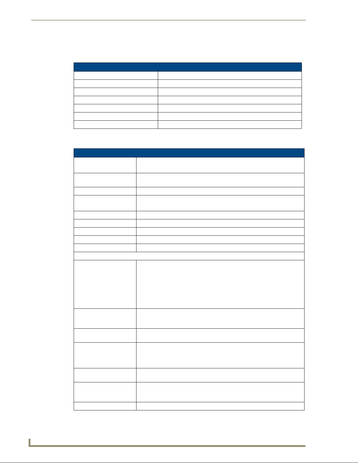
ViewStat Specifications
ViewStat Specifications
Control Ports • HVAC control
• ICSNet
Control Voltage 24 VAC ±20% or 24 VDC ±20% (delivered by an HVAC system or by an external
power supply)
Switched Voltage 18 – 30 VAC
Maximum Operating Current • 2 amps total at rated voltage, through all outputs.
• 1 amps through any one output.
Maximum Surge Current 2.0 A
Control Accuracy ±1.0° F (± 0.56° C)
Control Range 40° – 90° F (4.44° – 32.22° C)
Operating Range 32° – 99° F (0° – 37.22° C)
Baud Rate 9600
Front Panel Components:
Message display Two types of messages are displayed, Permanent and Temporary Messages.
• Permanent Messages are those that scroll continually during thermostat
operation.
• Temporary (flashing) Messages are intended to catch your eye and must be
reset to be removed from the display.
Thermostats are shipped with default (permanent) status messages (i.e. mode
status, fan status, equipment status).
Scroll/Set-up buttons The Scroll/Set-Up buttons function with the set-up features of the thermostat
(see theSet Up and Configuration section on page 39). These buttons are
located beneath the faceplate.
Main LCD display The MAIN DISPLAY (see FIG. 16 on page 23) provides the mode status, tem-
perature and system status information.
Mode button Five modes of operation are available: OFF, COOL, HEAT, AUTO, and EM.
HEAT (for heat pumps only). The mode of operation indicates how you want
your heating and cooling equipment to operate. This button is located beneath
the faceplate.
Fan button The fan can be operated continuously (FAN ON) or only when there is a need to
heat or cool. This button is located beneath the faceplate.
Enter button The Enter (or Network Override) button is used to override the home automation
system, to clear temporary flashing messages on the message display and with
the set-up features of the thermostat.
Adjust buttons The Adjust buttons adjust the heating and cooling temperature settings.
2
ViewStat Communicating Thermostat
Page 9
Product Information
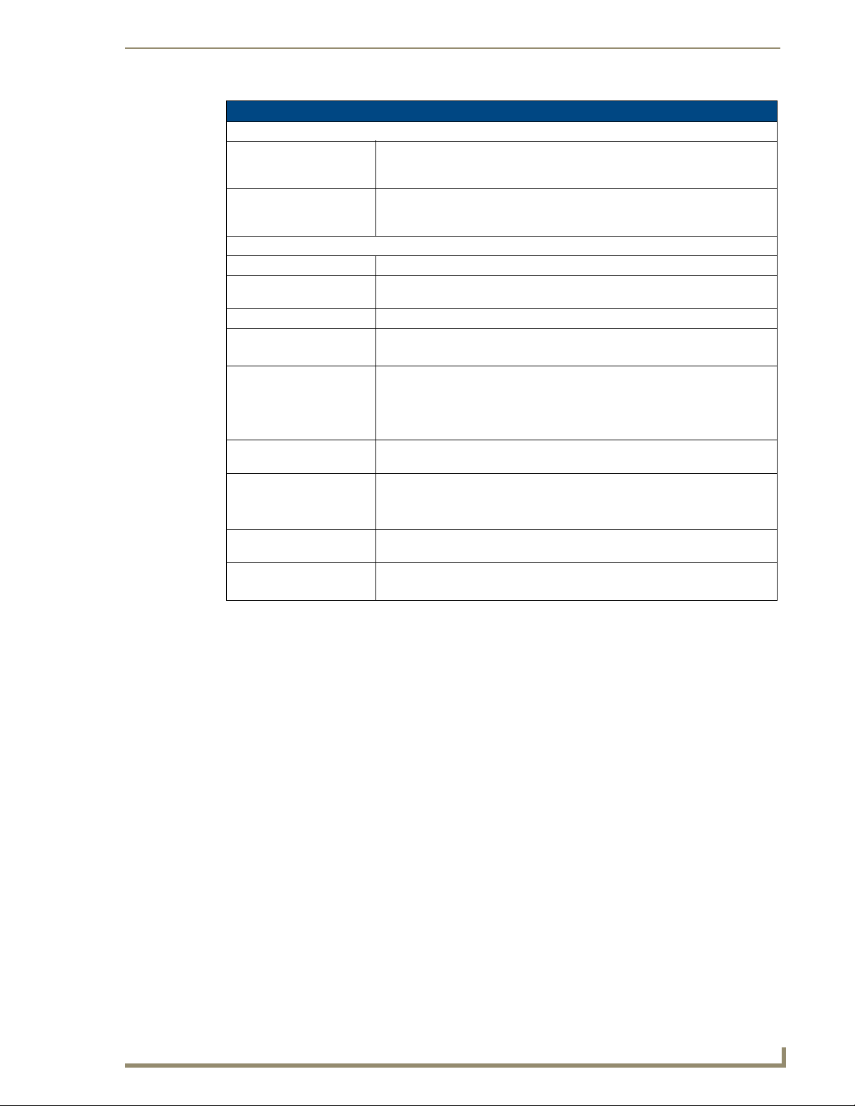
ViewStat Specifications (Cont.)
Circuit Board Components:
Communication and HVAC
Equipment connectors
DIP Switch 4-position DIP switch that configures the thermostat for various application types
Enclosure:
Material White plastic with hinged faceplate and removable front panel.
ViewStat Dimensions
(HWD)
Weight 5.29 oz. (150 grams)
Included Accessories • Cat5 Suppression Ferrite
Optional Accessories • VST-TTM Remote Temperature support module (FG944-10)
Remote Temperature
Sensors:
VST-TSF Dimensions: • Cable length: 9.00"(228 mm)
VST-TSO Dimensions
(HWD):
Weight: • VST-TSF: 0.5 lb (0.23 kg)
Terminals with captive-wire connectors that connects the Thermostat, HVAC
equipment, control system, remote sensors and power supply. Refer to the Wir-
ing the Thermostat section on page 20 for details.
(Servant/Master, Electric/Fossil, Single/Multi, Heat Pump/Heat-Cool). Refer to
the Setting the DIP Switch section on page 9 for details.
5.01" x 5.52" x 1.15"
(12.72 cm x 14.02 cm x 2.92 cm)
• 24 VAC Suppression Ferrite
• VST-TRH Remote Temperature/Humidity support module (FG944-20)
• VST-TSF Flush-mount indoor remote sensor (FG944-30)
• VST-TSO Duct/outdoor remote sensor (FG944-40)
• Sensor depth: 0.85" (22 mm)
• Sensor diameter: Ø1.50 (Ø38 mm)
• 2.75" x 1.44" x 1.75
(70 mm x 37 mm x 44 mm)
• VST-TSO: 0.75 lb (0.34 kg)
Support Module Specifications
There are two types of support modules available for the ViewStat:
VS T- TTM Te m per a t ure M o d ul e : The VST-TTM support module offers versatility in climate
control. A set of onboard dip switches on the VST-TTM circuit board allow you to determine
whether you want the two remote temperature sensor inputs to control, monitor or do a
combination of both. This temperature data is sent back to the ViewStat Thermostat, allowing you
to accurately control and monitor temperature in a given area or multiple areas.
VS T- TRH Te m p er a t ure a n d Hu m i dit y M odu l e : The VST-TRH support module brings further
versatility to the HVAC system. A set of onboard dip switches on the VST-TRH circuit board allow
you to determine whether you want the two remote temperature sensor inputs to control, monitor,
or both. The temperature/humidity data is sent back to the ViewStat, allowing you to accurately
control and monitor temperature/humidity in a given area or multiple areas.
ViewStat Communicating Thermostat
3
Page 10
Product Information
The ViewStat supports up to four Support Modules, and can display any one of the following:
The remote temperature on support module address 1 if its mode is set to "Control".
The average temperatures of all support modules set to "Control" mode.
The humidity of the VST-TRH (Temperature and Humidity Module) set to "Control" mode.
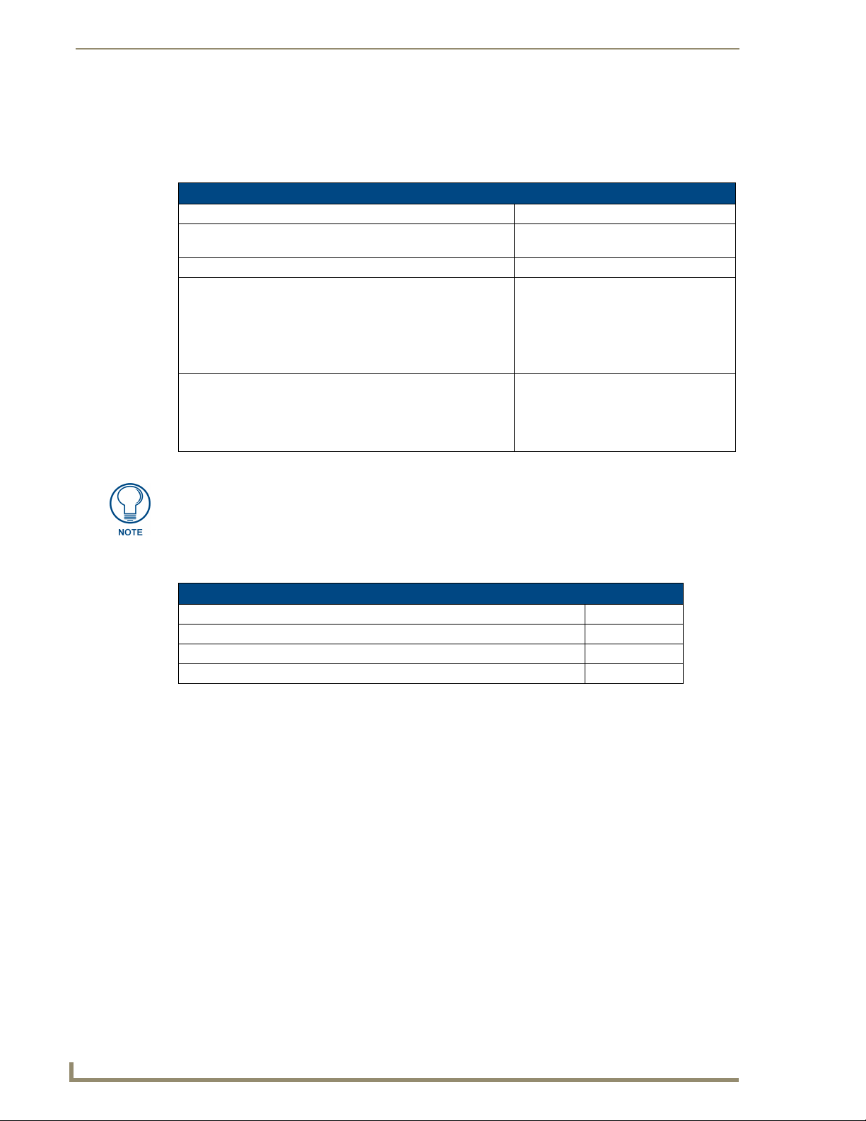
VST-TTM and VST-TRH Remote Sensor Specifications
Power supply 18 to 30 VAC or DC (24 V Nominal)
Support Module Dimensions (HWD) 2.50" x 3.50" x 0.88"
(63 mm x 89 mm x 22 mm)
Max. relative humidity 90% (non-condensing)
Temperature:
• Accuracy: Comfort Range: (60°F - 80°F): ± 1°F
Control Range: (40°F - 100°F): ± 2°F
Operating Range: (-40°F - 185°F): ± 3°F
• Maximum Display Range: -40°F - 185°F
Humidity (VST-TRH only):
• Accuracy: Comfort Range: (10% - 45%): ± 3%
Control Range: (10% - 90%): ± 5%
• Maximum Display Range: 0% - 90%
Refer to theSupport Module Installation and Wiring section on page 33 for
information on configuring, installing and wiring the support modules and remote
temperature sensors.
Maximum Cable Distances
Maximum Cable Distances
Between the VST and NetLinx or LandMark Controller: 1000’ (304.8m)
Between support module and VST: 1000’ (304.8m)
•Max. cumulative cable length between multiple support modules and VST: 1000’ (304.8m)
Between support module and remote sensor: 300’ (91.44m)
4
ViewStat Communicating Thermostat
Page 11
Product Information
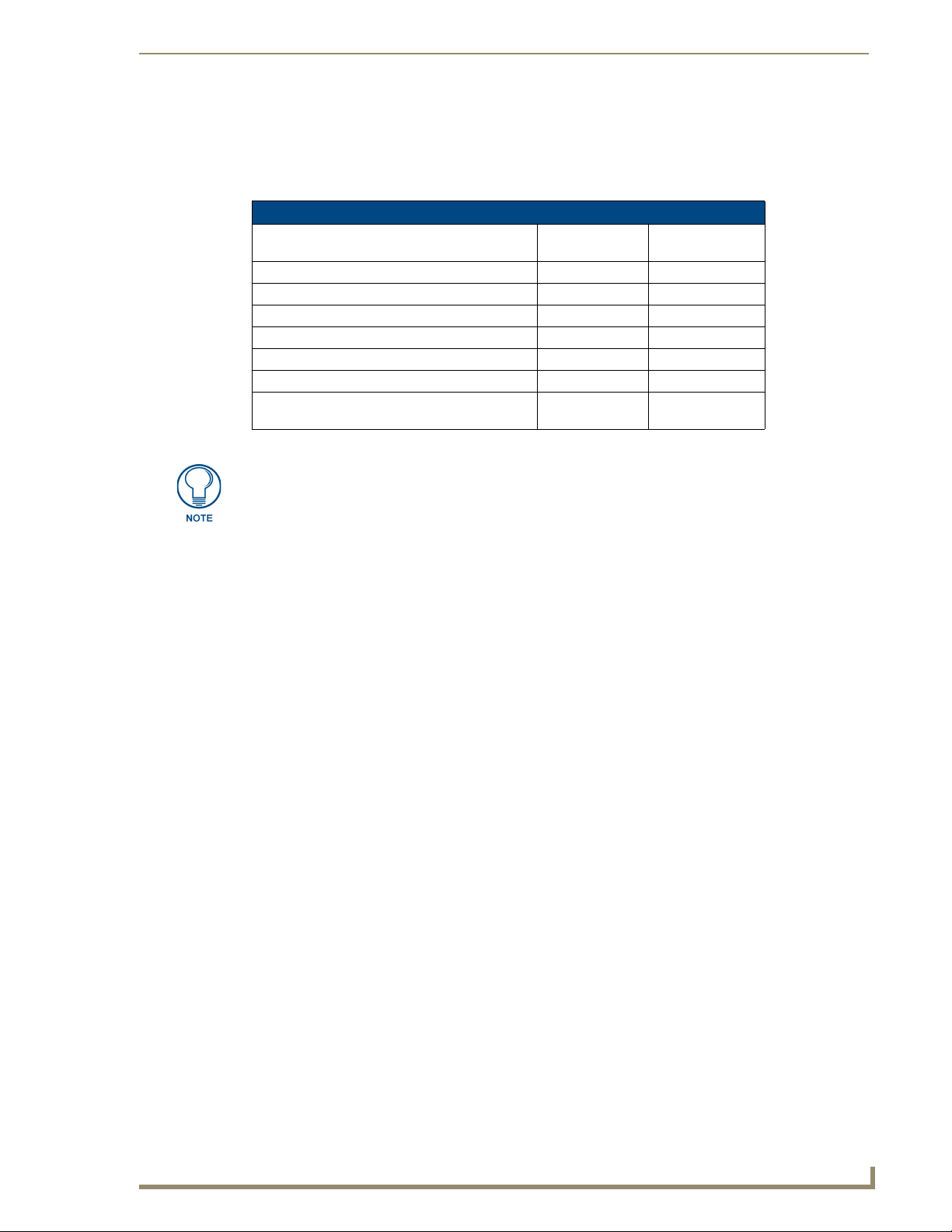
HVAC System Pre-Installation Check List
Before getting started, determine what type of heating system is/will be installed in the house. Then use the
following table to determine if the proper numbers of wires are available, depending on the HVAC System
type.
HVAC System Pre-installation Check List
Application # of HVAC
Wires
Single Stage Furnace & AC 5 FIG. 18 on page 26
Two Stage Furnace & Two Stage AC 7 FIG. 19 on page 27
Roof Top Unit (Two Stage Heat & Two Stage Cool) 7 FIG. 20 on page 28
Boiler with AC (Two Transformers) 5 FIG. 21 on page 29
Single Stage Heat Pump 7 FIG. 22 on page 30
Two Stage Heat Pump 9 FIG. 23 on page 31
First Stage Radiant Floor Heat
Second Stage Furnace One Stage of Cooling 6 FIG. 24 on page 32
In addition to the wires necessary to support the HVAC system control, an RJ45terminated Cat5 cable is necessary to support NetLinx or Landmark communications
(see theViewStat Installation and Wiring section on page 7 for details).
Wiring Diagram
ViewStat Communicating Thermostat
5
Page 12

Product Information
6
ViewStat Communicating Thermostat
Page 13
ViewStat Installation and Wiring
This section covers the installation, wiring and checkout of a ViewStat Communicating Thermostat System.
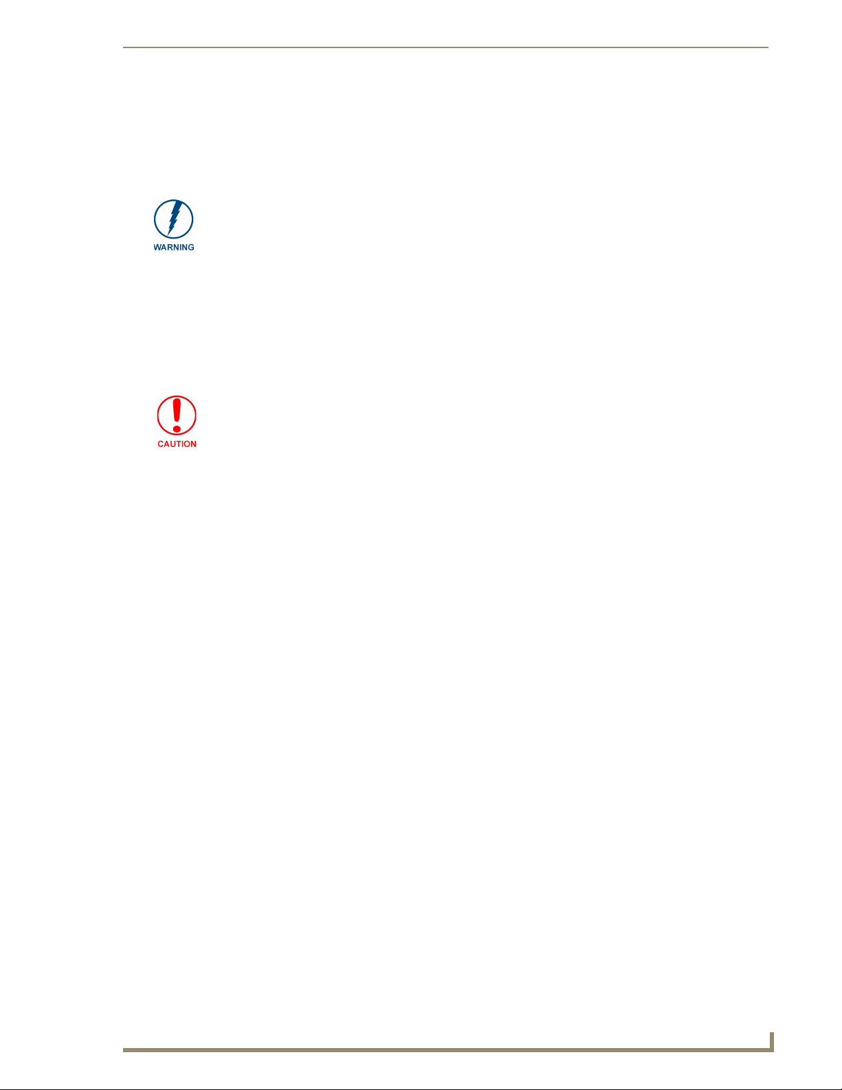
1. 120 volts may cause serious injury from electrical shock. Disconnect electrical power to the
HVAC system before starting installation. This system is a low-voltage system.
2. Improper installation may cause serious injury from electrical shock. This system must be
installed by a qualified contractor in accordance with NEC Standards and applicable local and state
codes.
Disconnecting Power to All HVAC Equipment
Since the ViewStats are wired directly to the HVAC equipment, the power must be shut off at the equipment.
This can generally be accomplished by turning off the disconnect switch located near the equipment. If an
obvious disconnect switch is unavailable, you will need to remove the circuit breaker or shut down the fuse
serving the equipment.
Failure to disconnect power could result in damage to the HVAC equipment or thermostats. Leave
power disconnected until all other electrical connections have been made and checked for
accuracy.
ViewStat Installation and Wiring
Selecting the Thermostat Location
Determine if the thermostat will be operating alone, or with remote temperature sensors. If the unit is standalone there are certain measures that must be taken to ensure accurate temperature control.
Stand-alone thermostat mounting criteria
One ViewStat per HVAC system.
Mount on an interior wall.
In a room frequently occupied.
At least 18 inches (45.72 cm) from any outside wall.
Approximately 5 feet (1.52 m) above the floor. Check with local building codes for height
requirements in commercial applications.
DO NOT locate the thermostat:
Behind doors, in corners or other dead air spaces.
In direct sunlight or near lamps, appliances or other sources of radiant heat.
On an outside wall or wall exposed to an unconditioned space (i.e. garage, etc.).
In the flow path of a supply register, in stairways or near outside doors.
On a wall where concealed pipes and/or duct work will affect the thermostat.
Near sources of electrical interference such as arcing relay contacts.
With remote temperature sensors
Follow the guidelines for placement of the sensors and locate the thermostat indoors where operating range
(see specs) will not be violated (i.e. do not install in a cold garage or hot equipment room). See the Support
Module Installation and Wiring section on page 33 for details.
ViewStat Communicating Thermostat
7
Page 14
ViewStat Installation and Wiring
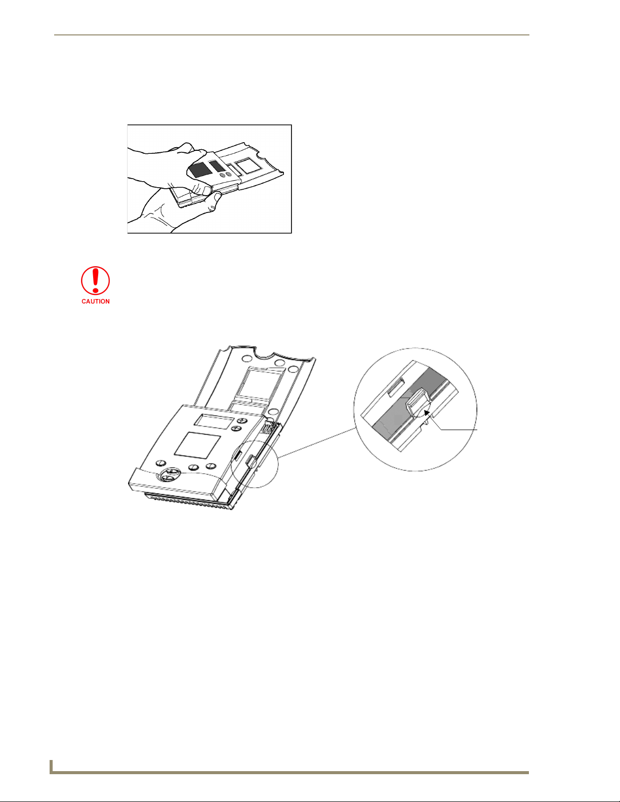
Removing the Faceplate from the Base
No tools are required to disassemble the thermostat – just use your hands to pull the front panel off of the base
(FIG. 2).
FIG. 2 Pulling the front panel off of the base
Loss of internal programs may result from static discharge to thermostat circuit board.
Touch a grounded metal object to discharge any static charge before handling the
circuit board.
While holding the base of the thermostat, apply pressure to the base of the latch with your thumb (FIG. 3).
Both sides have a latch, but it is easiest to unlatch one side at a time.
FIG. 3 Location of latch on base (one latch on each side)
Press base
here
8
ViewStat Communicating Thermostat
Page 15
ViewStat Installation and Wiring
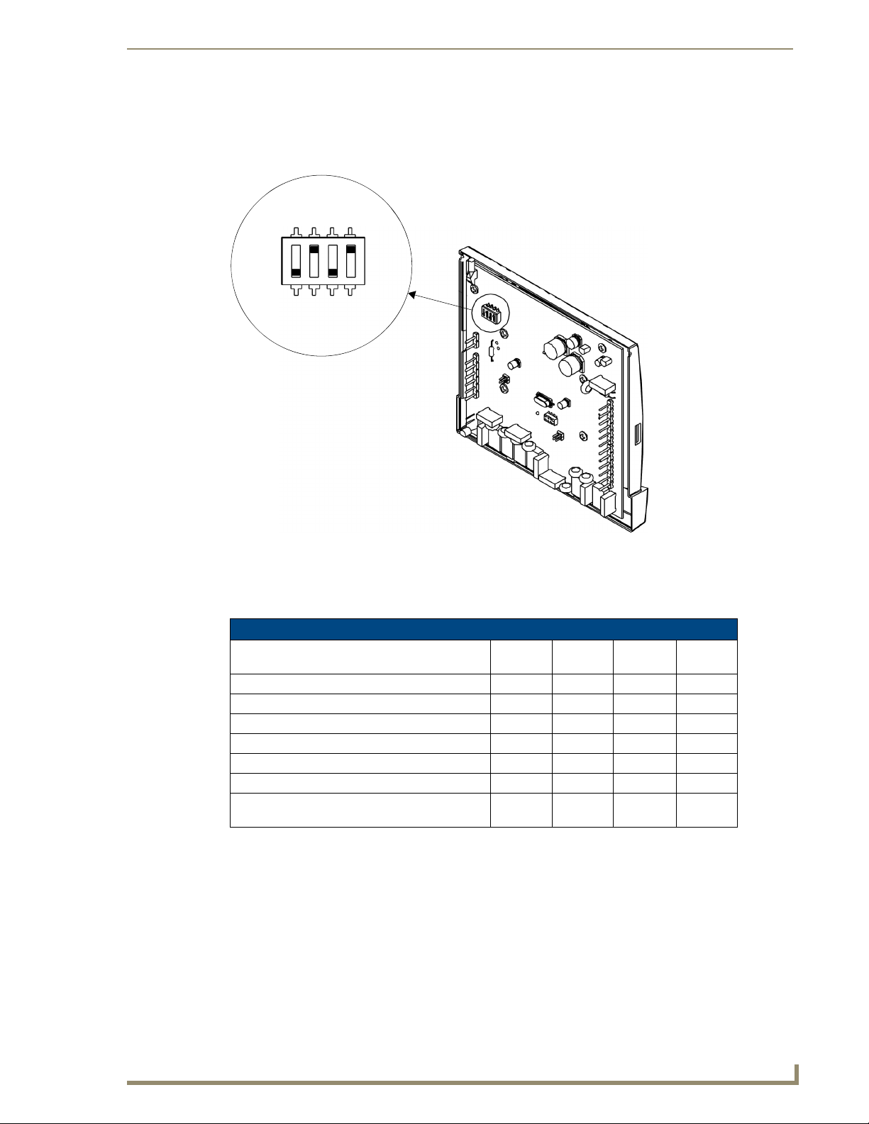
Setting the DIP Switch
Set the DIP switch located on the thermostat circuit board (FIG. 4) according to the application needs (see the
DIP Switch Settings table below for details).
FOSSIL
MULTI
MASTER
ON
OFF
SERVANT
H/C
SINGLE
HT.PUMP
ELECTRIC
FIG. 4 Setting the DIP Switch
The following table shows what each switch corresponds to depending on position. Switch one should be set in
the “OFF Servant” position unless you plan to broadcast readings from remote temperature sensors to other
thermostats in the system when there is no control system in place.
DIP Switch Settings
Application Switch #1Switch #2Switch #3Switch
Single Stage Furnace & AC Servant Fossil Single H/C
Two Stage Furnace & Two Stage AC Servant Fossil Multi H/C
Roof Top Unit (Two Stage Heat & Two Stage Cool) Servant Fossil Multi H/C
Boiler with AC (Two Transformers) Servant Fossil Single H/C
Single Stage Heat Pump Servant Electric Single HT. Pump
Two Multi-stage Heat Pump Servant Electric Multi HT. Pump
First Stage Radiant Floor Heat,
Second Stage Furnace One Stage of Cooling
Servant Fossil Multi H/C
#4
Reassembly
No tools required – line up pins on circuit board with the corresponding terminal blocks. Use your hands to
push the front panel securely to the mounted base.
ViewStat Communicating Thermostat
9
Page 16
ViewStat Installation and Wiring
C
(black)
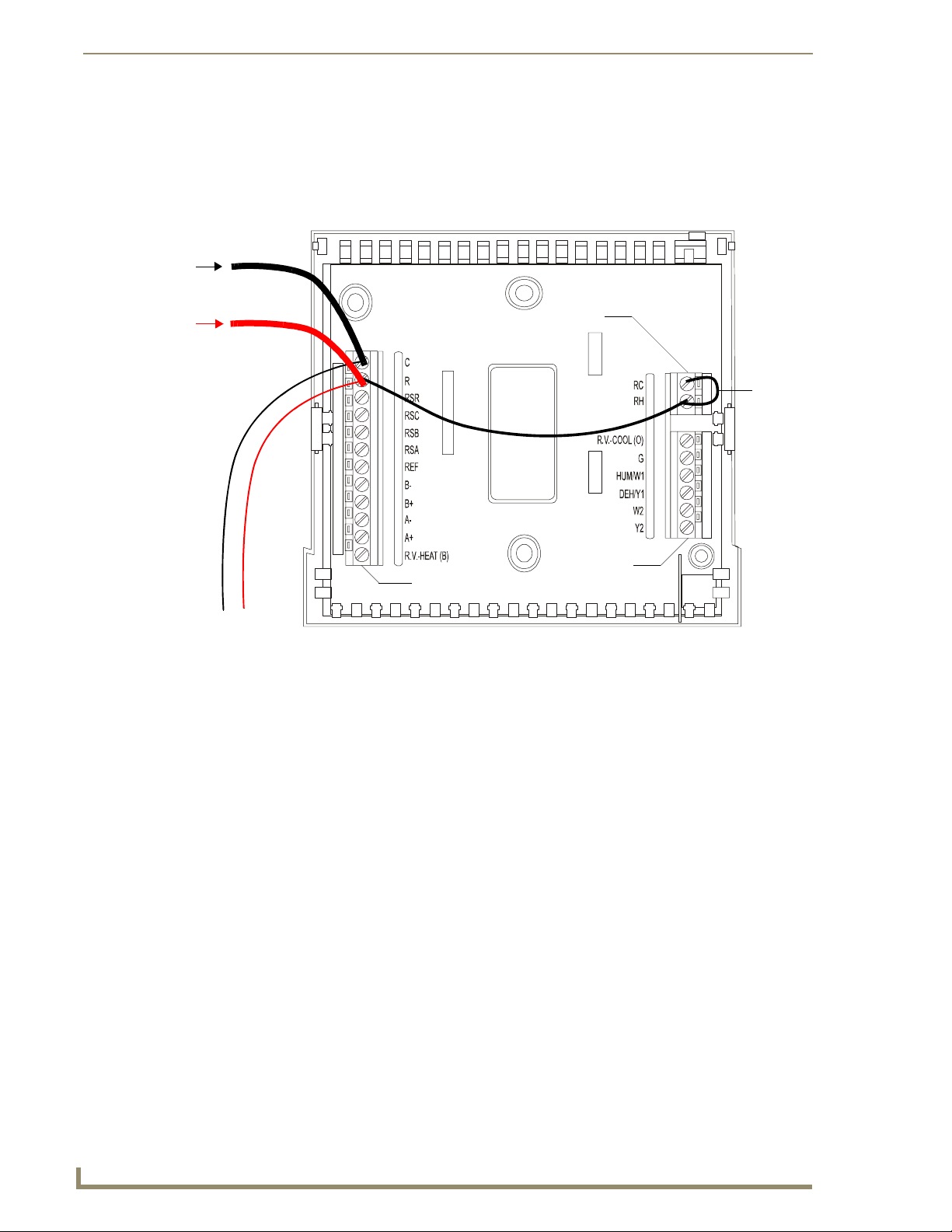
Attaching the MiniVerter to the ViewStat
Before attaching the MiniVerter to the rear of the ViewStat, connect the wiring, as described below:
1. Detach the faceplate from the base of the ViewStat.
2. Pull the stripped/tinned wires through the cutout in the center of the base (FIG. 5).
ommon
from 24 VAC
HVAC System
Power (red)
from 24 VAC
HVAC System
Power
Te r mi n al
cutout
jumper
from RC
to RH
Equipment
Communication
Terminal
from Miniverter
FIG. 5 ViewStat base with Communication, Power and Equipment terminals
terminal
Before mounting the ViewStat, you must attach the MiniVerter to the rear panel of the ViewStat, as described
below:
1. Detach the faceplate from the base of the ViewStat.
2. Pull the stripped/tinned wires through the cutout in the center of the base (FIG. 5)
3. Connect the communications wiring:
a. Blue to B-
b. Orange to B+
c. Red/White to A-
d. Black/White to A+
4. Connect the power wiring:
a. Black to C
b. Red to R
5. Install a jumper from RH to RC.
6. Insert the MiniVerter (connector-side first) into the guide-slots located on the bottom of the MiniVerter
mounting bracket (FIG. 6).
7. Slide the MiniVerter back into its locking position in the mounting bracket.
8. With the connector-side of the MiniVerter seated in the guide-slots, gently press the opposite side of the
MiniVerter in and down, to snap it into its locked position on the mounting bracket.
10
ViewStat Communicating Thermostat
Page 17
ViewStat Installation and Wiring
ViewStat base (top view)
1
Insert the MiniVerter
(connector-side down)
inside the mounting bracket.
mounting bracket
FIG. 6 Inserting the MiniVerter into the mounting bracket (top view).
into the guide slots
MiniVerter
Snap into place
3
Slide the MiniVerter into
2
locking position in
the bracket.
MiniVerter card
Repeated installation and removal of the MiniVerter bracket may result in damage to
the bracket.
9. Connect the Cat-5 RJ-45 connector on the MiniVerter to the Control System (Master or ICSNet Hub).
Wiring the VST-TSTAT to a VST-DIST Distribution Panel
The optional VST-DIST Distribution Panel (not included) connects to up to eight VST-TSTAT thermostats,
providing a convenient and effective method of wiring multiple thermostats to the control system's RS422
serial interface port.
The VST-DIST provides one RS422 interface to the control system and eight RS422 interfaces for the
thermostats.
Since the VST-DIST provides an RS422 interface to the control system, a MiniVerter (VST-MVRT)
is not required for communication.
The VST-DIST is intended for use with the VST-TSTAT, and is not intended for use with the VST,
which includes a MiniVerter.
The VST-DIST includes an Instruction Manual from the manufacturer with detailed
installation instructions, and a decal on the inside of the front cover (reproduced in
FIG. 7) gives wiring information for the panel.
ViewStat Communicating Thermostat
11
Page 18
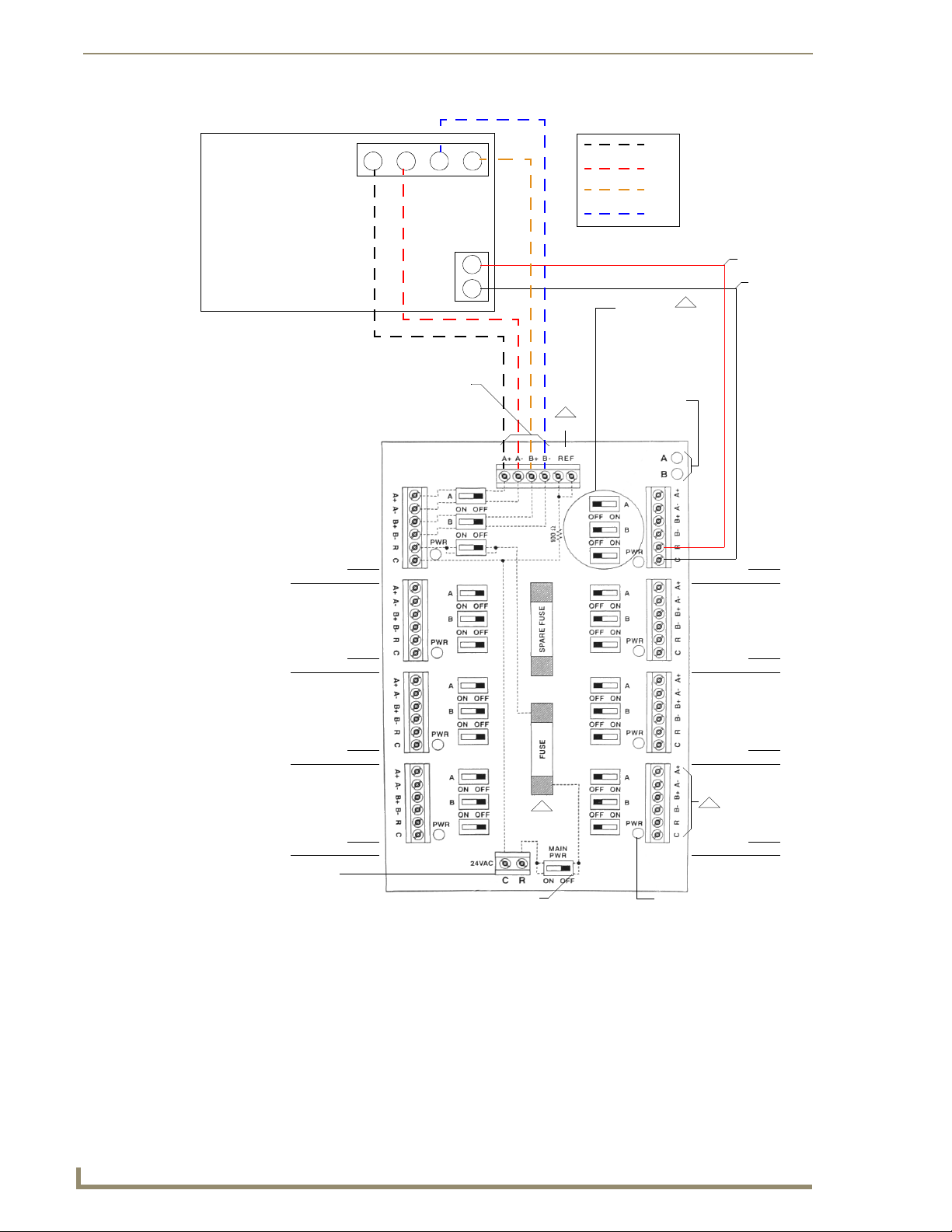
ViewStat Installation and Wiring
Communications
Wire to Protocol Adapter,
other Distribution Panels or
directly to Automation System
A: Transmit B: Receive
REF
2
Rx+
Rx-
Tx+
Tx-
Switches
A - Allows Transmit
Communications
B - Allows Received
Communications
PWR - Turns power to
thermostat on/off
LEDs light when
communications are
transmitted (A)
or received (B)
24VAC
GND
3
ADDRESS #
ADDRESS #
ADDRESS #
ADDRESS #
Tra ns fo rm er
24 V, 40 VA minimum
up to 8 thermostats
C - 24 V (common) (-) if DC
R - 24 V (hot) (+ ) if DC
Main Power Switch
Turns main power to
Distribution Panel on/off
1
ADDRESS #
ADDRESS #
ADDRESS #
4
ADDRESS #
LED will light up when
power to thermostat is switched on
FIG. 7 Wiring the VST-TSTAT to a VST-DIST Distribution Panel
Mounting the Base to a Wall
There are four screw holes located on the base of the thermostat; two are for a junction box mounting, along
with two for alternate mounting spacing. Use one of the holes on the top and one on the bottom.
1. Place the base over the wire hole opening in the wall; level the base and mark the screw hole mounting
locations (leveling required for appearance only).
2. If using supplied wall anchors, drill 3/16" hole in the center of the marked locations and tap in the wall
anchors. If using the supplied screws only, drill a 3/32" hole in the center of the marked locations.
12
ViewStat Communicating Thermostat
Page 19
ViewStat Installation and Wiring
Minimize wire entry hole size and seal – drafts from inside the wall could affect
temperature readings.
3. Fasten the base to the wall with the supplied screws.
4. Seal wire entry using caulk, drywall putty or insulation.
Loss of internal programs may result from static discharge to thermostat circuit board.
Installer must touch a grounded metal object before handling the circuit board.
Connecting the ViewStat to AMX Control Systems
When a Mini Verter is used the Viewstat has a single RJ-45 jack on the rear panel, and uses ICSNet cabling to
connect to NetLinx or Landmark control systems.
The terms "PhastLink" and ICSNet" are essentially interchangeable within the
context of cabling/connectors. They both use a standard 10BaseT type connection
(i.e. Category 5 wire and RJ-45 connectors), and they share the same pinout
information for the RJ-45 jacks. Generally the term "PhastLink" is used when dealing
with Landmark, and "ICSNet" is used when describing NetLinx control systems.
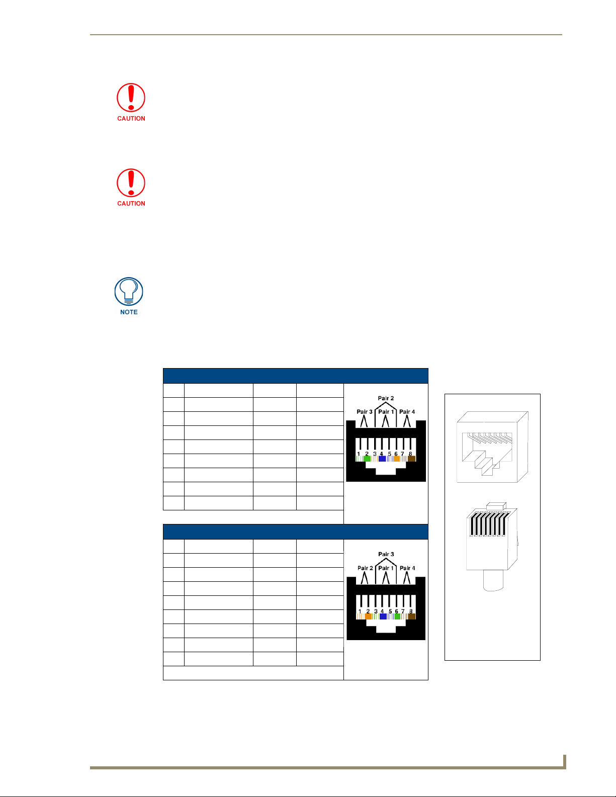
The wires should be connected in the standard manner described in the following table. If standard EIA/TIA
568A/B color coding is followed, wiring problems will be minimized.
PHASTLink RJ-45 Pinout Information (EIA/TIA 568 A)
Pin W ire Color Polarity Function
1 White/Green + Transmit
2 Green - Transmit
3 White/Orange - Mic
4 Blue - Ground
5 White/Blue + 12 VDC
6 Orange + Mic
7 White/Brown + Receive
8Brown - Receive
TIA 568A
NetLinx RJ-45 Pinout Information (EIA/TIA 568 B)
Pin W ire Color Polarity Function
1 Orange/White + Transmit
2 Orange - Transmit
3 Green/White - Mic
4 Blue - Ground
5 White/Blue + 12 VDC
6 Green + Mic
7 White/Brown + Receive
8Brown - Receive
TIA 568B
1 2 3 4 5 6 7 8
(female)
1 2 3 4 5 6 7 8
RJ-45 connector pin configurations
(male)
ViewStat Communicating Thermostat
13
Page 20
ViewStat Installation and Wiring
It is important that the correct pairing is observed. Transmit, Receive, and Mic
need to be on twisted pairs. Splitting pairs (e.g., using a white/green wire with a blue/
white wire for transmit) will result in increased crosstalk, and may result in bus failure
or noise on the intercom.
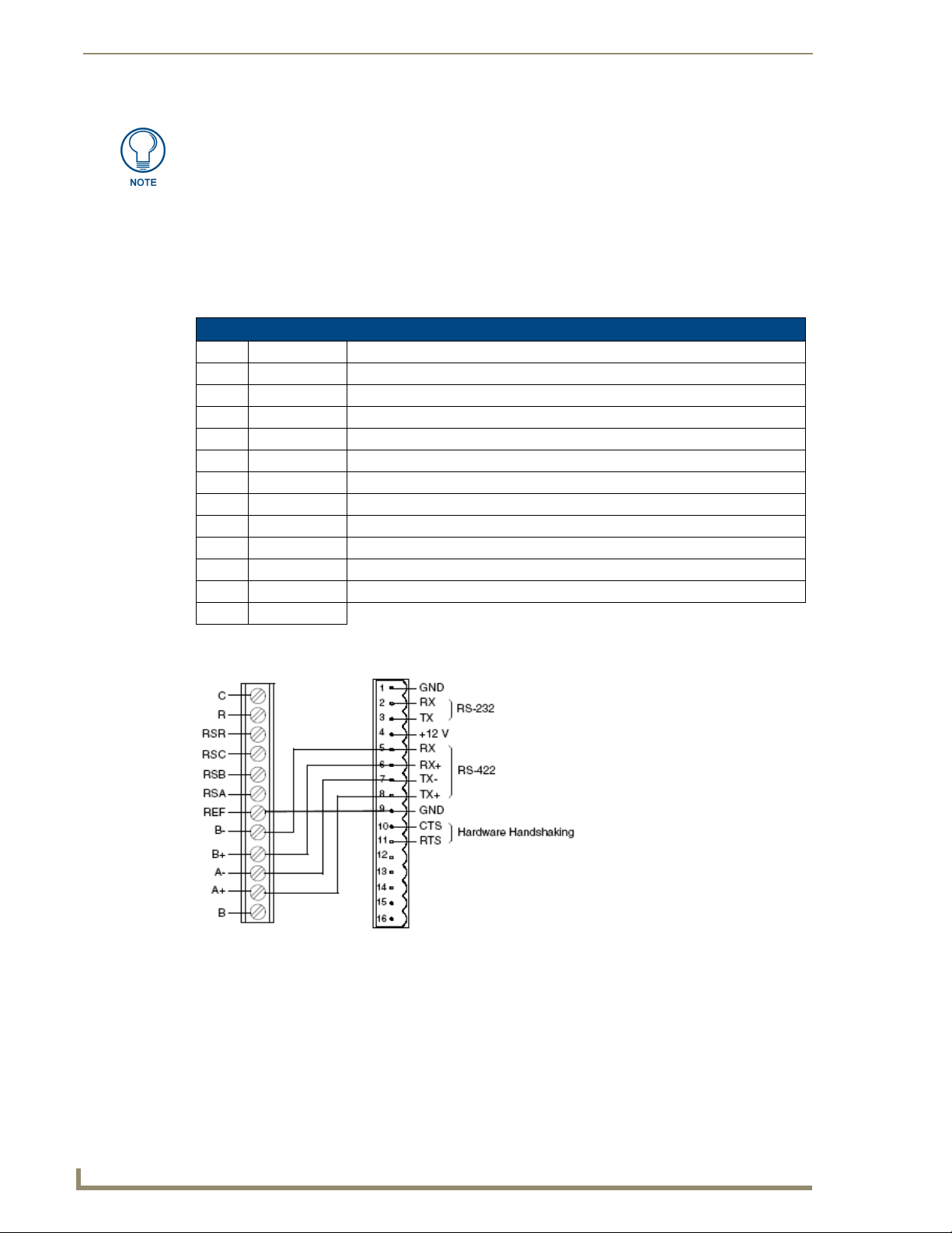
Connecting to an Axcess Control System (via AXC-232++, AXB-EM232, or Axcent3/PRO)
To connect the ViewStat to an Axcess control system via an Axcess Cardframe (cardframe must be equipped
with an AXC-232 232/422/485 Control Card), AXB-EM232 Enhanced Master, or Axcent3(PRO) Controller,
refer to the card-edge pinout information below:
Axcess System Card Edge Pinouts
Pin Signal Function
1 GND Ground (RS-232)
2 RX Receive data (RS-232)
3 TX Transmit data (RS-232)
4 +12V Power
5 RX - Receive data (RS-422)
6 RX + Receive data (RS-422)
7 TX - Transmit data (RS-422)
8 TX + Transmit data (RS-422)
9 GND Ground
10 CTS Clear-to-send (hardware handshaking)
11 RTS Ready-to-send (hardware handshaking)
12-16 not used
FIG. 8 shows the wiring configuration for Axcess systems:
ViewStat
(Communication
terminal)
FIG. 8
Connecting the ViewStat to an Axcess Control System
Axcess
Control
System
AXC-232(++)
or
AXB-232(++)
14
ViewStat Communicating Thermostat
Page 21
ViewStat Installation and Wiring
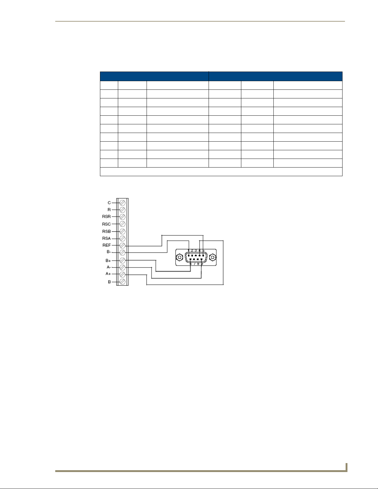
Connecting to an Axcess Master Controller via the RS232/422/485 (DB-9) Port
The table below lists the connector pins, signal types, and signal functions for RS-232/RS-422/RS- 485 DB-9
(male) connector on an Axcess Master Controller (i.e. Axcent3 or Axcent3/PRO).
DB-9 Pinouts Wiring and Baud Configurations
Pin Signal Function RS-232 RS-422 RS-485
1 RX- Receive data X X (strap to pin 9)
2 RXD Receive data X
3 TXD Transmit data X
4 TX+ Transmit data X X (strap to pin 6)
5 GND Signal ground X X
6 RX+ Receive data X X (strap to pin 4)
7 RTS Request to send X
8 CTS Clear to send X
9 TX- Transmit data X X (strap to pin 1)
The X’s show where to terminate the wires on the DB-9 connector.
FIG. 9 shows the wiring configuration for Axcess systems (using the DB-9 PROGRAM port).
ViewStat
(Communication
terminal)
FIG. 9
Connecting the ViewStat to an Axcess Control System via the RS232/422/485 (DB-9) port
ViewStat Communicating Thermostat
RS232/422/485
Por t
15
Page 22
ViewStat Installation and Wiring
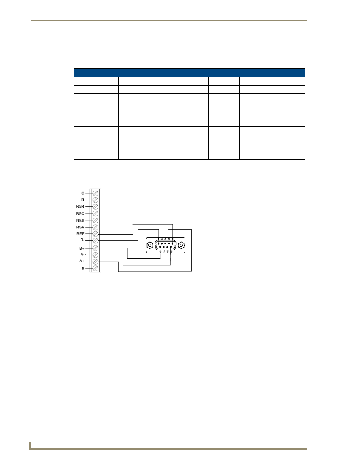
Connecting to NetLinx Integrated Controllers via the RS232/422/485 (DB-9) Port
The table below lists the connector pins, signal types, and signal functions for RS-232/RS-422/RS- 485 DB-9
(male) connector on an NetLinx Integrated Controllers (i.e. NI-2000/3000/4000).
DB-9 Pinouts Wiring and Baud Configurations
Pin Signal Function RS-232 RS-422 RS-485
1 RX- Receive data X X (strap to pin 9)
2 RXD Receive data X
3 TXD Transmit data X
4 TX+ Transmit data X X (strap to pin 6)
5 GND Signal ground X X
6 RX+ Receive data X X (strap to pin 4)
7 RTS Request to send X
8 CTS Clear to send X
9 TX- Transmit data X X (strap to pin 1)
FIG. 9 shows the wiring configuration for NetLinx systems (using the DB-9 PROGRAM port).
The X’s show where to terminate the wires on the DB-9 connector.
16
ViewStat
(Communication
terminal)
FIG. 10
RS232/422/485
Por t
Connecting the ViewStat to an NetLinx Integrated Control System via the RS232/422/485 (DB-9) port
ViewStat Communicating Thermostat
Page 23
ViewStat Installation and Wiring
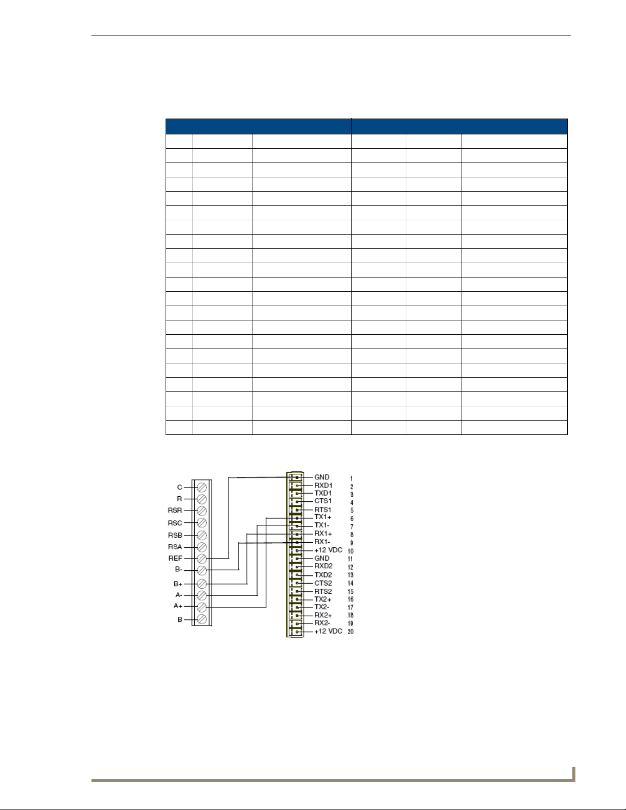
Connecting to a NetLinx Master controller via NXC-COM card
The Viewstat can connect to a NetLinx NXF Cardframe or NXI equipped with a NXC-COM Dual COM Port
Control Card. The following table shows the card edge pinout information for the NXC-COM card.
NXC-COM2 Pinouts NXC-COM2 Wiring Configuration
Pin Signal Function RS-232 RS-422 RS-485
1 GND Signal ground X X
2 RXD1 Receive data X
3 TXD1 Transmit data X
4 CTS1 Clear to send X
5 RTS1 Request to send X
6 TX1+ Transmit data X X (strap to pin 8)
7 TX1- Transmit data X X (strap to pin 9)
8 RX1+ Receive data X X (strap to pin 6)
9 RX1- Receive data X X (strap to pin 7)
10 +12 VDC Power Optional Optional
11 GND Signal ground X X
12 RXD2 Receive data X
13 TXD2 Transmit data X
14 CTS2 Clear to send X
15 RTS2 Request to send X
16 TX2+ Transmit data X X (strap to pin 18)
17 TX2- Transmit data X X (strap to pin 19)
18 RX2+ Receive data X X (strap to pin 16)
19 RX2- Receive data X X (strap to pin 17)
20 +12 VDC Power Optional Optional
FIG. 11 shows the wiring configuration for NetLinx systems.
ViewStat
(Communication
terminal)
FIG. 11
Connecting the ViewStat to a NetLinx Control System
ViewStat Communicating Thermostat
17
Page 24

ViewStat Installation and Wiring
Connecting to a LandMark Control System
PhastLink cables are used to connect all PhastLink-compatible devices, including keypads, dimmers, J-box IR
devices, amplifiers, audio switches, etc. The table below lists the RJ-45 pinout information.
RJ-45 Pinout Information
PinWire Color PolarityFunctio
1 White/Green + Transmit
2 Green - Transmit
3 White/Orange - Mic
4 Blue - Ground
5 White/Blue + 12 VDC
6 Orange + Mic
7 White/Brown + Receive
8 Brown - Receive
PhastLink uses a standard 10Base-T connection (i.e. Category 5 wire and RJ-45 connectors). The wire should
be connected in the standard manner. If a consistent color code is used, wiring problems will be minimized.
It is important that the correct pairing is observed. Transmit, Receive, and Mic need to be on twisted pairs.
Splitting pairs (e.g., using a white/green wire with a blue/white wire for transmit) will result in increased
crosswalk, and may result in bus failure or noise on the intercom.
n
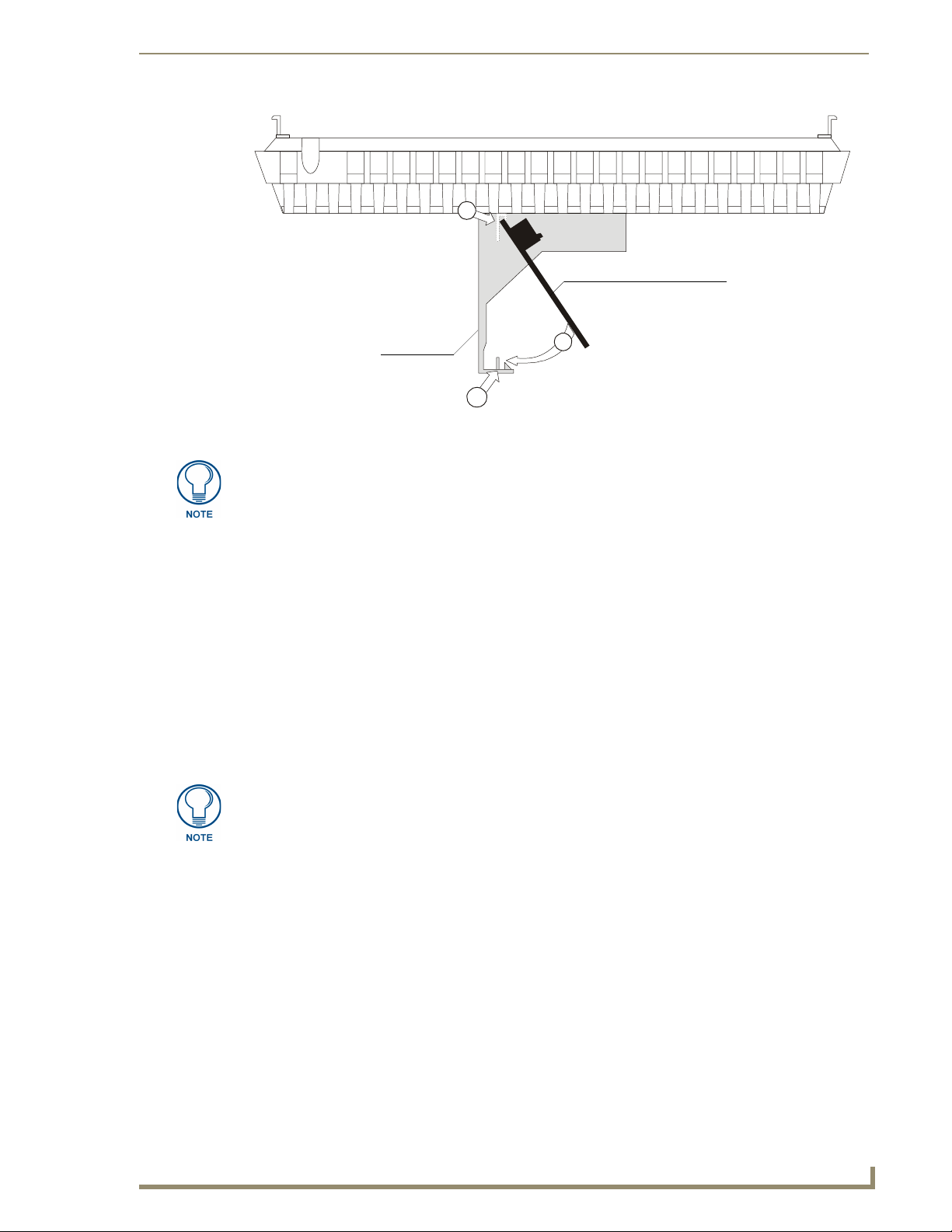
Installing the Cat5 Suppression Ferrite
Before connecting the ICSNet cable, install the Cat5 Suppression Ferrite (provided), as described below (no
tools required):
Release the latch to
open the plastic
enclosure.
FIG. 12
Installing the Cat5 Suppression Ferrite
Insert the Cat5
cable and close
the enclosure.
Installation complete.
1. The Cat5 suppression ferrite is housed in a plastic enclosure, with a latch release on one side. Pull to
release the latch and open the enclosure.
2. Insert the Cat5 cable.
3. Snap the enclosure shut with the cable inside, and you’re done.
Connecting to a NetLinx Control System
To connect a single ViewStat to a NetLinx control system, use ICSNet cabling to connect the
RJ-45 jack on the ViewStat to any available ICSNet jack on the NetLinx Master. The maximum cabling
distance between the ViewStat and Master is 1,000 ft (304.8 m).
To connect multiple ViewStats to a NetLinx system, use a NetLinx Hub (NXC-NH) to add additional ICSNet
ports to the system, connect the RJ-45 jack on the ViewStat to an available ICSNet jack on the Hub.
18
ViewStat Communicating Thermostat
Page 25

ViewStat Installation and Wiring
Connecting to a Landmark Control System
To connect a single ViewStat to a Landmark control system, use PhastLink cabling to connect the RJ-45 jack
on the ViewStat to any available PhastLink jack on the Landmark Master (MCU). The maximum cabling
distance between the ViewStat and MCU is 1,000 ft (304.8 m).
To connect multiple ViewStats to a Landmark system, use a Landmark Hub (PLH-RPT) to add additional
PhastLink ports to the system, connect the RJ-45 jack on the ViewStat to an available PhastLink jack on the
Hub.
Connecting the ViewStat to the HVAC System
Before connecting the ViewStat to the
HVAC system, install the 24 VAC
Suppression Ferrite, to eliminate any
potential noise problems.
Installing the 24 VAC Suppression Ferrite
Before connecting the 24 VAC power supply cable to the HVAC system, install the 24 VAC Suppression
Ferrite (provided), as described below (no tools required):
Pass the 24VAC power cord
through the ferrite bead.
FIG. 13 Installing the 24 VAC Suppression Ferrite
Loop the cable around
and pass it through
the ferrite bead again.
Gently pull the cable
to eliminate excess
slack - installation
complete.
1. Pass the 24 VAC power cable through the ferrite bead once.
2. Loop the cord around, and pass it through the ferrite bead once more.
3. Gently remove any excess slack in the cable, and you’re done.
ViewStat Communicating Thermostat
19
Page 26

ViewStat Installation and Wiring
Wiring the Thermostat
1. Strip 1/4" (0.63 cm) of insulation from each wire to be used.
2. Secure wires into the terminals on the base according to the appropriate wiring diagram, as described in
the following table. Refer to the Wiring Diagrams section on page 26. Use color-coding practices (i.e.
white wire to W terminal) whenever possible.
3. Check each wire to ensure it is securely fastened, not broken, and exposed wires are not touching.
Communication and Equipment terminal wiring definitions
The following table describes the Communication and Equipment terminal wiring definitions (see FIG. 5 on
page 10).
• Single Stage Furnace & AC Refer to FIG. 18 on page 26
• Two Stage Furnace & Two Stage AC Refer to FIG. 19 on page 27
• Roof Top Unit (Two Stage Heat & Two Stage Cool) Refer to FIG. 20 on page 28
• Boiler with AC (Two Transformers) Refer to FIG. 21 on page 29
• Single Stage Heat Pump Refer to FIG. 22 on page 30
• Two Stage Heat Pump Refer to FIG. 23 on page 31
• First Stage Radiant Floor Heat
Second Stage Furnace One Stage of Cooling
Refer to FIG. 24 on page 32
Communication and Equipment Terminal Wiring Definitions
Communication Terminal
C Thermostat Voltage (common)
R Thermostat Voltage (hot)
RSR (support module) Thermostat Voltage (hot)
RSC (support module) Thermostat Voltage (common)
RSB/RSA (support module) Support module communication (half-duplex)
REF Ground Reference
B-/B+ Receive
A-/A+ Transmit
Equipment Terminal
RC Switched Voltage (cool)
RH Switched Voltage (heat)
RV COOL (O) Reversing Valve - Cool (energized in Cool mode)
RV HEAT (B) Reversing Valve - Heat (energized in other modes)
GFan
HUM/W1 1st stage Heat (non-heat pump)
-or3rd stage Heat AND 1st Stage Emergency Heat (heat pump)
-orHumidification (with humidity control sensor)
20
ViewStat Communicating Thermostat
Page 27

ViewStat Installation and Wiring
Communication and Equipment Terminal Wiring Definitions (Cont.)
Equipment Terminal (Cont.)
DEH/Y1 1st stage Cooling (non-heat pump)
-or1st stage Compressor (heat pump)
-orDehumidification (with humidity control sensor)
W2 2nd stage Heat (non-heat pump)
-or2nd stage Emergency Heat (heat pump)
Y2 2nd stage Cooling (non-heat pump)
-or2nd stage Compressor (heat pump)
Connecting the ViewStat to the HVAC System
A qualified HVAC technician should perform these steps step to ensure proper
termination.
1.
Make sure the HVAC system power is off.
2. The following figures (FIG. 14, FIG. 15) show wiring diagrams for several different HVAC equipment
types. Use these diagrams as a reference only. Use color coding where possible.
a. FIG. 14 shows a typical heat/cool wiring schematic:
MULTI-STAGE FURNACE
2ND
STAGE
HEAT
FAN
RELAY
2ND STAGE
1ST STAGE
1ST
STAGE
HEAT
24
VAC
L2
120
VAC
COOL
COOL
L1
Y2
W2
Y1
W1
G
C
R
MULTI-STAGE A/C
2ND
1ST
STG
COOL
STG
COOL
Y2
Y1
C
CAUTION!
ENSURE HVAC SYSTEM POWER
IS OFF BEFORE WIRING
(common)
(from MiniVerter)
FIG. 14 Typical heat/cool wiring schematic
USE 18-20 GA. THERMOSTAT CABLE. NUMBER OF CONDUCTORS
REQUIRED DEPENDS ON THE HVAC SYSTEM BEING CONTROLLED
C
R
RSR
RSC
RSB
RSA
REF
BB+
AA+
B
REFER TO THE THERMOSTAT INSTALLATION SHEET FOR
INTERNAL SCHEMATIC, THERMOSTAT CHECK-OUT
PROCEDURES AND OTHER HVAC WIRING DETAILS
Black
Red
(power)
RC
RH
O
G
W1
Y1
W2
Y2
ViewStat Communicating Thermostat
21
Page 28
ViewStat Installation and Wiring
b. FIG. 15 shows a typical heat/cool wiring schematic:
OUTDOOR HEAT PUMP UNIT
USE 18-20 GA. THERMOSTAT CABLE. NUMBER
OF CONDUCTORS REQUIRED DEPENDS ON THE
HVAC SYSTEM BEING CONTROLLED
CAUTION!
ENSURE HVAC SYSTEM POWER
IS OFF BEFORE WIRING
INDOOR BLOWER/HEAT
REFER TO THE THERMOSTAT INSTALLATION
SHEET FOR INTERNAL SCHEMATIC, THERMOSTAT
CHECK-OUT PROCEDURES AND OTHER HVAC
WIRING DETAILS
2ND
STAGE
AUX.
HEAT
FAN
RELAY
UNIT
W2
1ST
STAGE
AUX.
HEAT
24
VAC
L2
120
VAC
W1
G
C
R
L1
REV
VALVE
HEAT
COMP.
B
2ND
STG
Y2
C
R
RSR
RSC
RSB
RSA
REF
BB+
AA+
B
1ST
STG
COMP.
Y1
REV
VALVE
COOL
DEFROST
O
W1
SERVICE
L
C
R
RC
RH
O
G
W1
Y1
W2
Y2
Red
(power)
Black
(common)
(from MiniVerter)
FIG. 15 Typical heat pump wiring schematic
For additional HVAC system wiring diagrams (for Single-Stage Furnace and AC,
Two-Stage Furnace and Two-Stage AC, Roof-Top Unit (Two-Stage Heat and TwoStage Cool), Boiler With AC (Two Transformers), and Single Stage Heat Pump
Configurations, refer to the Wiring Diagrams section on page 26.
22
ViewStat Communicating Thermostat
Page 29

ViewStat Installation and Wiring
Checking HVAC System Operation
Use the thermostat buttons to verify that the thermostat is controlling the equipment operation. A checkout
procedure is supplied in the installation instructions supplied with thermostat. This procedure will verify only
that the thermostat operates the equipment.
The HVAC installer may need to connect 24VAC to the R and C terminals to check HVAC operation. If the
automation system is to be installed after the HVAC installation, leave the R and C terminals connected to
ensure the HVAC system operates. If the automation system is installed before either the placement of HVAC
wiring or an external power supply is used, then do not connect HVAC wires to R and C.
When the thermostat is first turned on all of the graphics of the main LCD are momentarily displayed; this will
look like FIG. 16.
Message display
Scroll/Set-Up buttons
Main (LCD) display
Adjust buttons
FIG. 16 Front panel (with all graphics on Main LCD displayed)
Check Out Procedure
The following check-out procedure will turn the heating and cooling equipment on
and off. Do not operate in cooling at low outdoor temperatures. Do not operate in
heating at high outdoor temperatures. Refer to the HVAC equipment manufacturer
specifications for safe operating temperatures.
Use the Check Out procedure (below) to determine if the thermostat is controlling the HVAC equipment.
1. Press the Mode button, and look for the OFF message on the Main display.
2. Press the Fan button. The system blower should start and the message FAN ON appears on the Main
display. Press Fan again to stop.
3. Press the Mode button until the COOL message appears, along with the current cool setting on the Main
display.
4. Use the down arrow button to lower the set point 3°F below room temperature. In 5 to 10 seconds the
first stage of cooling begins, and the COOL message icon begins to flash. If there is a second stage it will
begin in four minutes.
5. Press the Mode button until OFF appears n the Main display. During Check-out, change the mode to
override the Minimum On time delays.
6. Press the Mode button until the HEAT message appears, along with the current heat setting in the Main
display.
ViewStat Communicating Thermostat
23
Page 30

ViewStat Installation and Wiring
7. Use the up arrow button to raise the set point 3°F above room temperature. In 5-10 seconds, the first stage
of heating begins and the HEAT message icon begins to flash. If there is a second stage it will begin in 4
minutes.
Heat Pump Only: The message HEAT -AUX is displayed when the auxiliary heat terminal (W1) is
energized. The LED on top of the thermostat will illuminate.
8. Press the Mode button until OFF appears in the Main display. During Check-out, change the mode to
override the minimum On time delays.
9. Press the Mode button until EM.HEAT appears on the Main display. Repeat step 7 to verify Emergency
Heat operation.
Optional HVAC Set-Up Features
There are a number of HVAC features that can be configured for the particular application. These include
temperature control options, display options and high/low balance points (heat pumps only).
Temperature control options
Balance points
Display options
To access these HVAC set-up features
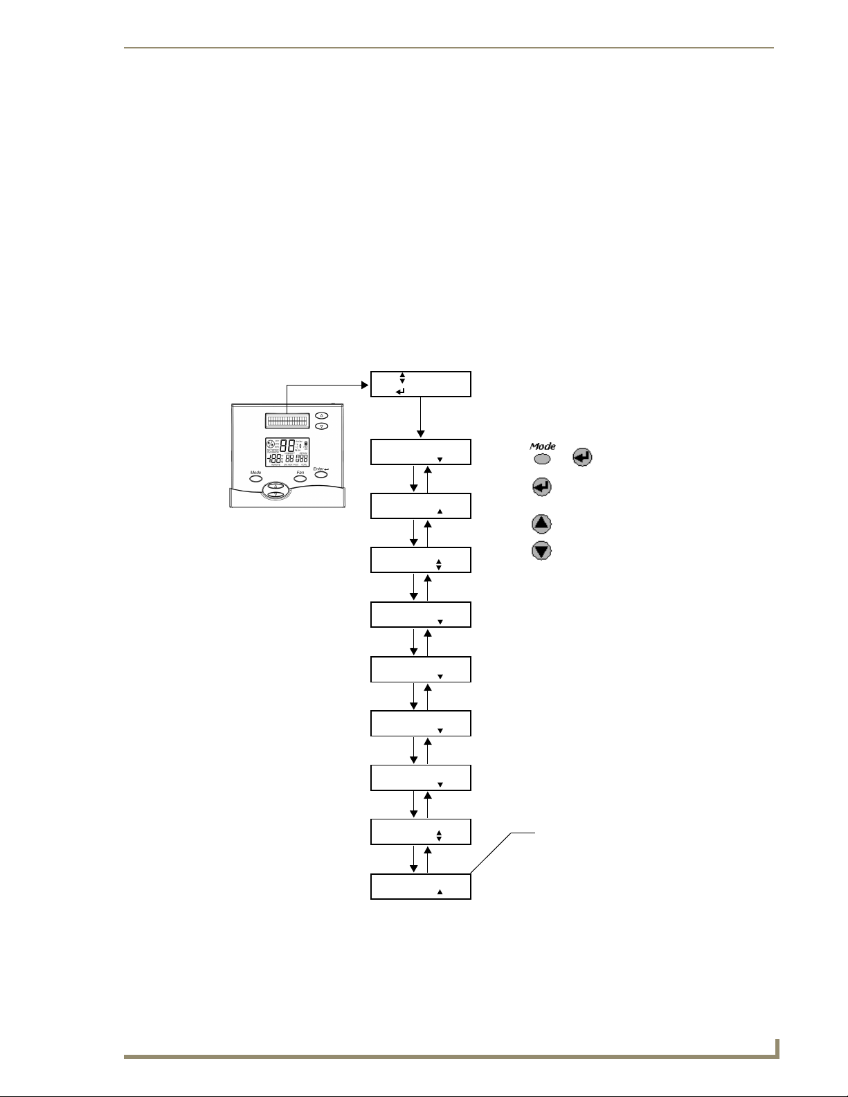
When first powered up, the message display will scroll through the current mode status, fan status, and
heating/cooling output status. This is referred to as Passive Display because you do not interact with it. To get
into the Set-Up Menu, press the Enter and Mode buttons at the same time. This is referred to as User
Interactive Display, as the user navigates through various menu and sub-menu selections to change variables.
Set-Up is menu driven but only one menu item is visible at a time. FIG. 32 on page 39 shows the entire Main
Menu. Selecting any one of the Main Menu items (by pressing the Enter button) will enter a corresponding
Sub-Menu. The Scroll Up and Scroll Down buttons are used to move between menu items or change values.
The Enter button is used to select a menu item or enter a value. When in Thermostat Set-Up, if none of the
three navigation buttons are pressed in 5 minutes, the display will return to Passive Display.
For detailed information on accessing and using the various Set-Up menus, refer to the Set Up and
Configuration section on page 39.
Address the Thermostats and Set Highest Address
These steps must be done at each thermostat for communication to work properly.
1. Press the Mode and Enter buttons simultaneously at the thermostat. It may take a couple of tries to get
them pressed together.
This will enter the Thermostat Set Up Menu. The first menu item that will appear on the text messaging
display is an informational item that indicates that only the Scroll Up, Scroll Down (two buttons located
immediately to the right of the text display) and the Enter buttons are used in thermostat set up. This will
remain on the display for approximately 5 seconds or until any of the three aforementioned buttons are
pressed. Thermostat Set Up is a series of sub-menu's that allow you to customize the ViewStat in various
ways. The Set Up and Configuration section on page 39 outlines the set up features. The following steps
will guide you only through Communications Set Up sub-menu (FIG. 17).
2. Press the Scroll Down button until the "Communications Set Up" menu shows on the display.
3. Press the Enter button to select this menu.
4. The first sub-menu item is "Set Thermostat ADDRESS". Press the Enter button to select this item.
5. Set the address between 1 and 64 using the Scroll Up and Scroll Down buttons.
Each thermostat must have a unique address (i.e. no two thermostats can have the same address)
Start with address 1 and increment by 1 for each new address - do not skip an address. This will
optimize communications speed.
24
ViewStat Communicating Thermostat
Page 31

ViewStat Installation and Wiring
Communica tions
Set Up More
FIG. 17 Setting the thermostat address
Set Thermostat
Address
Set Baud
Rate More
EXIT
Next
Network Address
1 to 64
No.of T-stats On
the Network
Select
Back
Write down the address for each thermostat.
9600
6. After the address has been selected, press the Enter button to store the address.
7. Use the Scroll Up and Scroll Down buttons to set the "Number of Stats on the Network" to the highest
address that will be on the thermostat network. This will be equal to the total number of thermostats on
the network (unless one or more addresses are skipped - see step 5).
This number must be set the same at each thermostat.
8. Press Enter to set the baud rate. The ViewStat must be set for 9600 baud to communicate with the
miniverter. This is the default setting, and you shouldn’t ever change this setting.
9. Press Enter to "Exit" the Communications Set Up sub-menu. This will return you to the main menu.
10. Press the Scroll Down button until "Exit" is displayed. Press the Enter button. The thermostat will then
reset and return to normal operation.
ViewStat Communicating Thermostat
25
Page 32

ViewStat Installation and Wiring
Wiring Diagrams
Single-stage furnace and AC configuration.
ViewStat
FIG. 18 Single-stage furnace and AC configuration
Red
(power)
(from MiniVerter)
Black
(common)
26
ViewStat Communicating Thermostat
Page 33
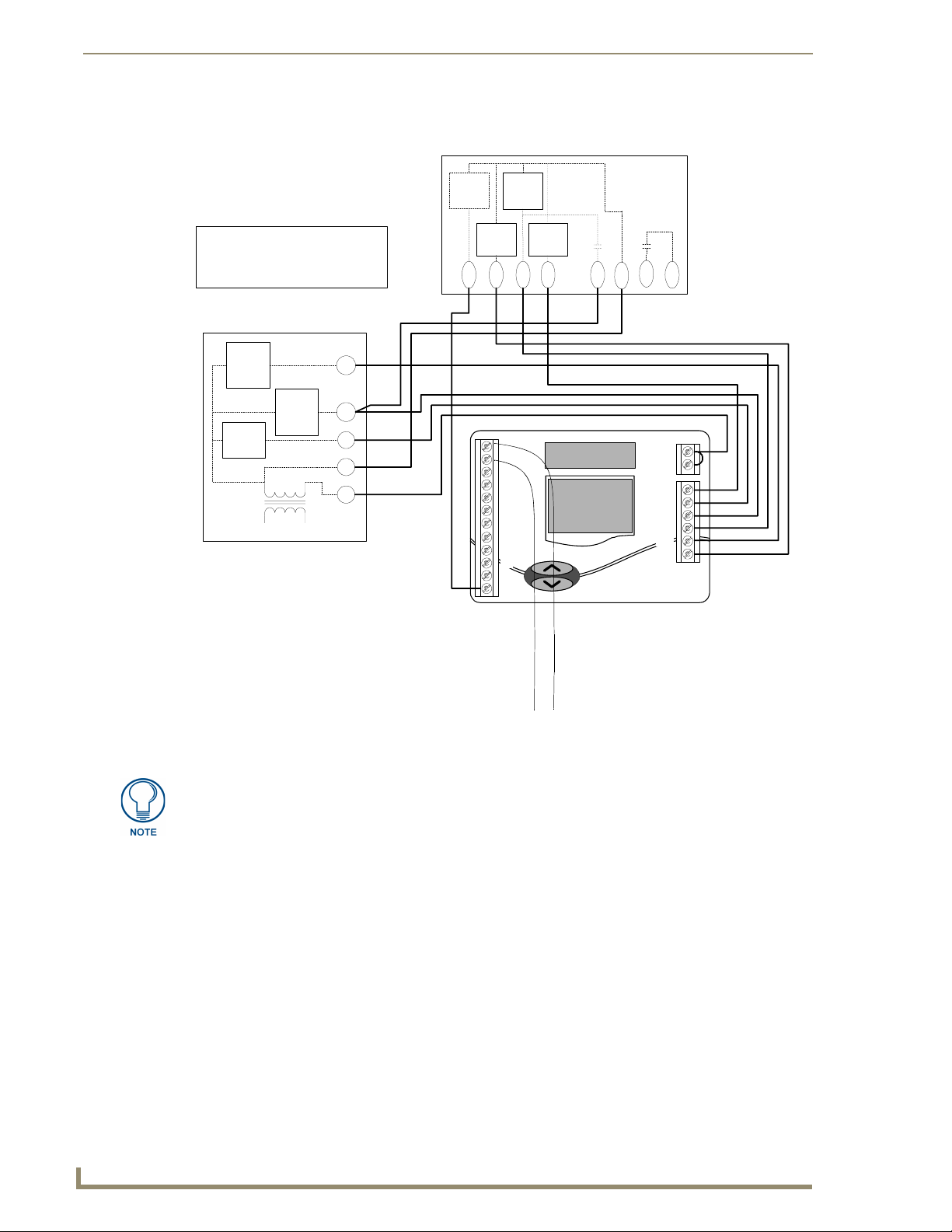
Two-stage furnace and two-stage AC configuration.
ViewStat
ViewStat Installation and Wiring
Red
(power)
(from MiniVerter)
FIG. 19 Two-stage furnace and two-stage AC configuration
IMPORTANT! The B terminal is for reversing valve-heat. DO NOT connect the B
terminal to the common side of the transformer.
Black
(common)
ViewStat Communicating Thermostat
27
Page 34

ViewStat Installation and Wiring
Roof top unit (two-stage heat and two-stage cool) configuration.
ViewStat
Red
(power)
(from MiniVerter)
FIG. 20 Roof top unit (two-stage heat and two-stage cool) configuration
Black
(common)
IMPORTANT! The B terminal is for reversing valve-heat. DO NOT connect the B
terminal to the common side of the transformer.
28
ViewStat Communicating Thermostat
Page 35
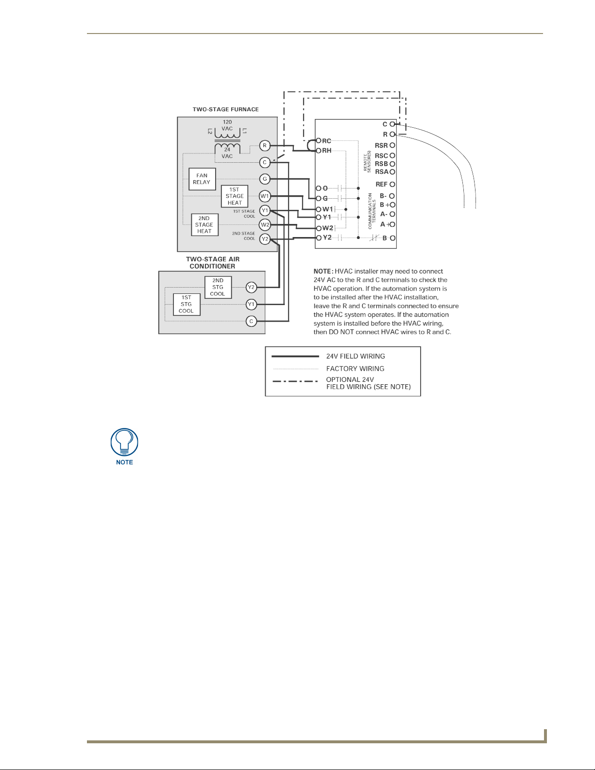
Boiler with AC (two transformers) configuration.
ViewStat Installation and Wiring
ViewStat
FIG. 21 Boiler with AC (two transformers) configuration
Red
(power)
(from MiniVerter)
Black
(common)
IMPORTANT! The B terminal is for reversing valve-heat. DO NOT connect the B
terminal to the common side of the transformer.
ViewStat Communicating Thermostat
29
Page 36
ViewStat Installation and Wiring
Single-stage heat pump configuration
ViewStat
Black
(common)
Red
(power)
(from MiniVerter)
FIG. 22 Single-stage heat pump configuration
IMPORTANT! The B terminal is for reversing valve-heat. DO NOT connect the B
terminal to the common side of the transformer.
30
ViewStat Communicating Thermostat
Page 37
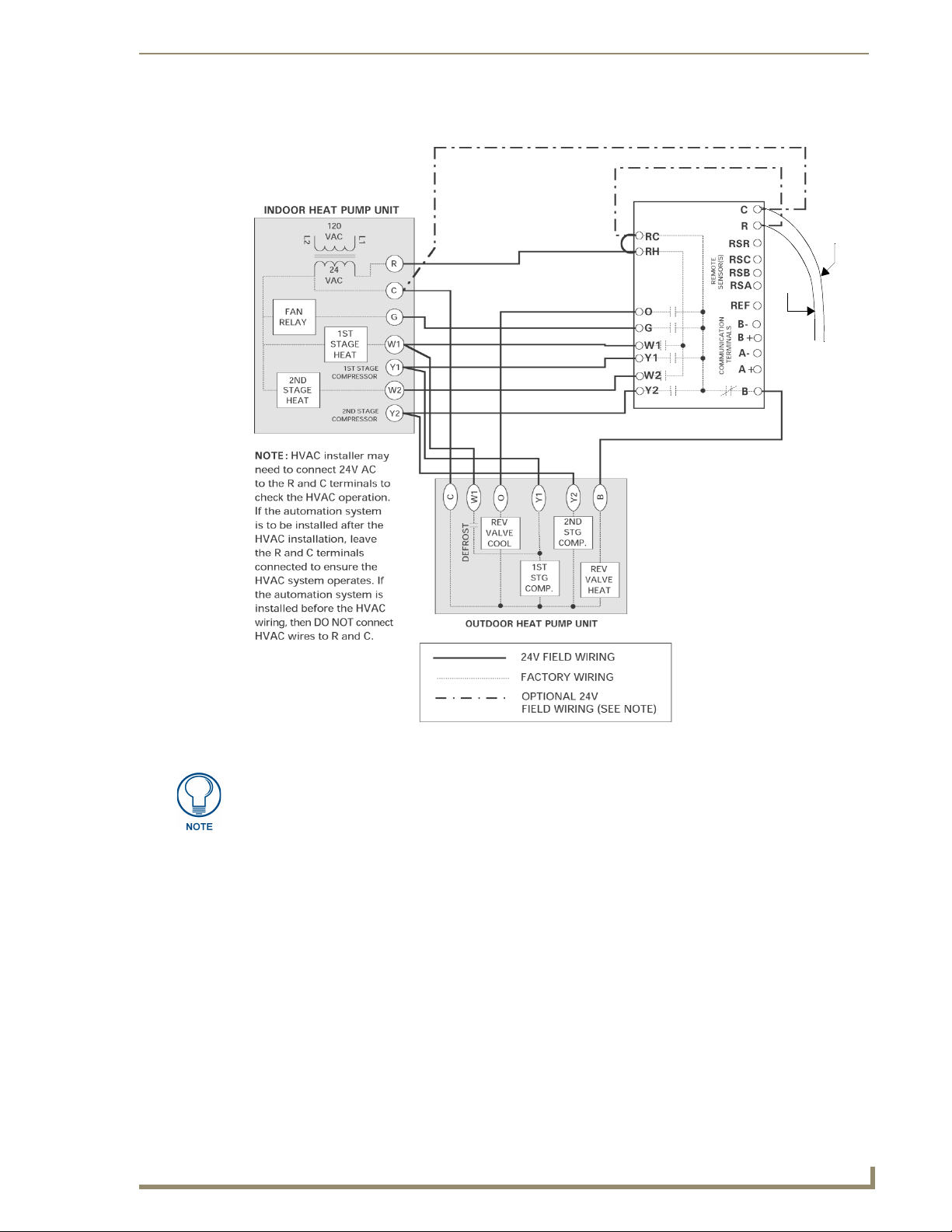
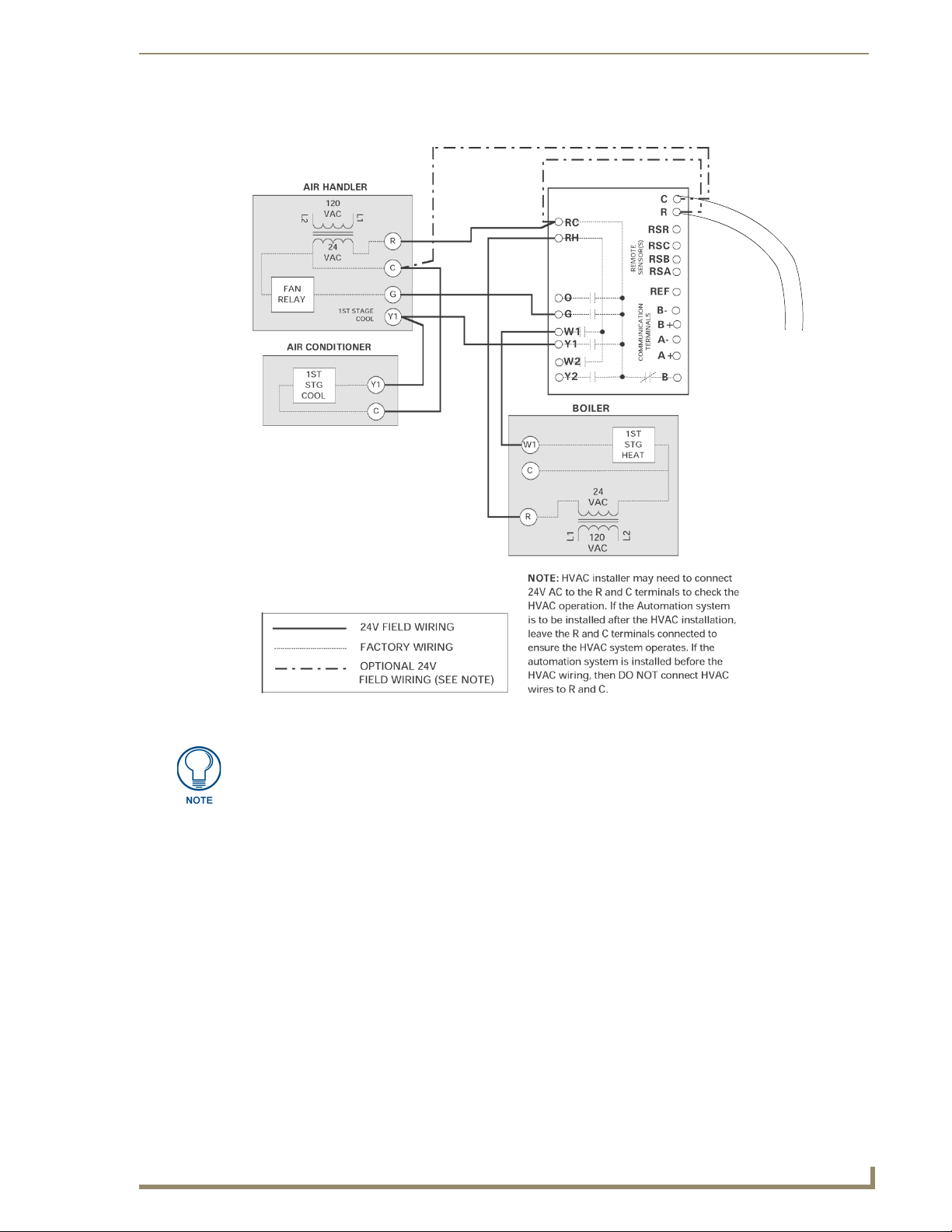
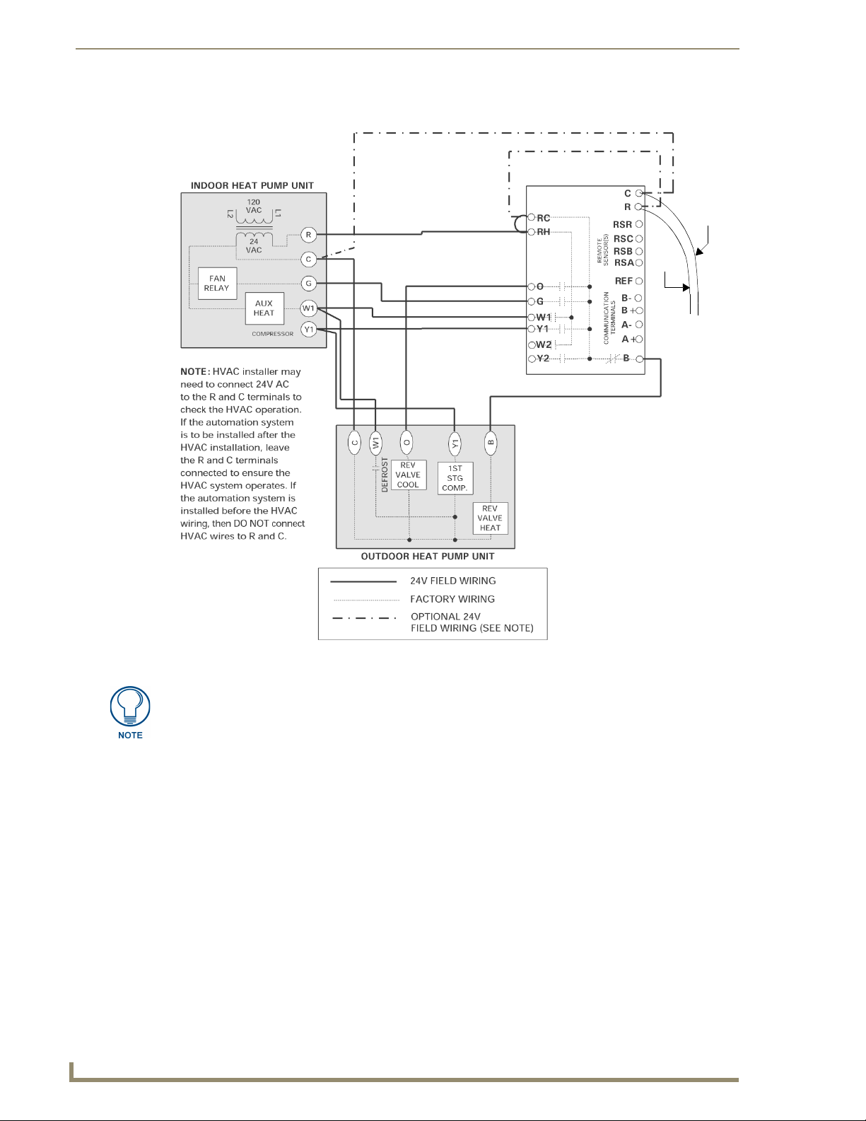
Two-stage heat pump configuration.
ViewStat Installation and Wiring
ViewStat
Black
(common)
Red
(power)
(from MiniVerter)
FIG. 23 Two-stage heat pump configuration
IMPORTANT! The B terminal is for reversing valve-heat. DO NOT connect the B
terminal to the common side of the transformer.
ViewStat Communicating Thermostat
31
Page 38
ViewStat Installation and Wiring
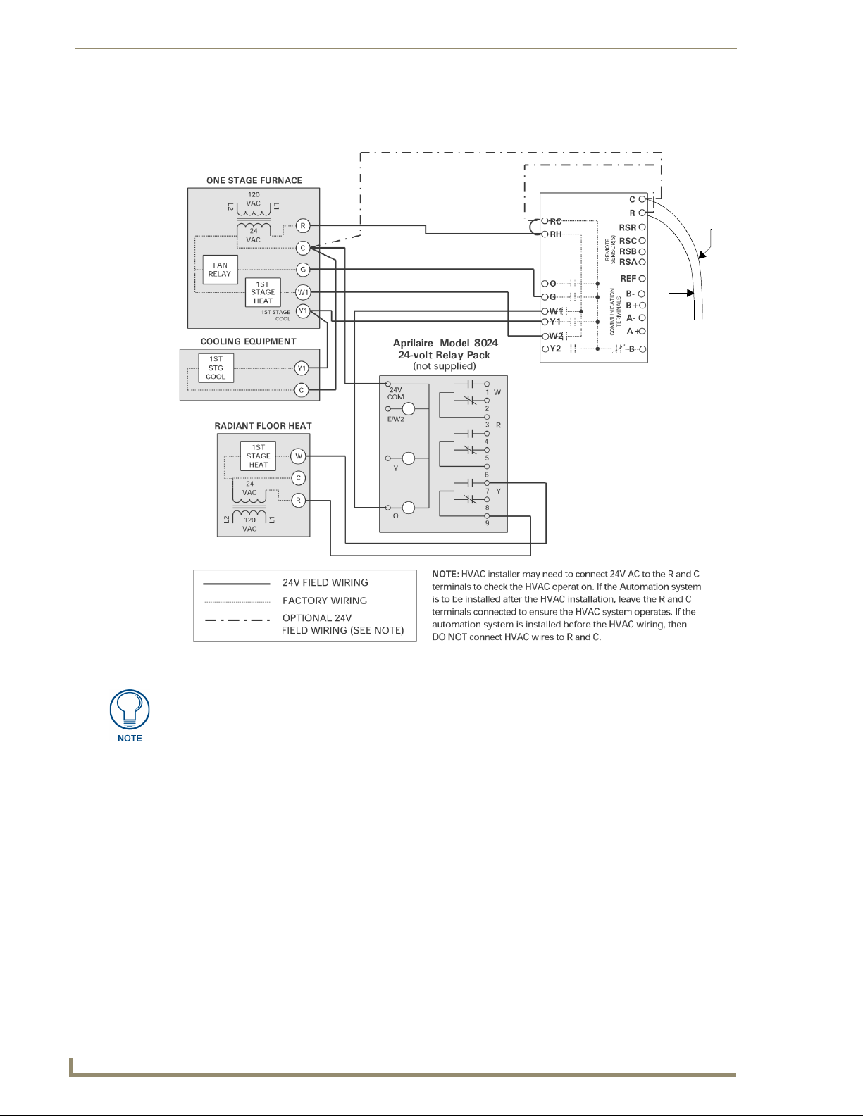
First- stage radiant floor heat, second-stage furnace one stage of cooling configuration.
ViewStat
Black
(common)
Red
(power)
(from MiniVerter)
32
FIG. 24 First-stage radiant floor heat, second-stage furnace one stage of cooling configuration
IMPORTANT! The B terminal is for reversing valve-heat. DO NOT connect the B
terminal to the common side of the transformer.
ViewStat Communicating Thermostat
Page 39
Support Module Installation and Wiring
Support Module Installation and Wiring
Follow the guidelines for placement of the support modules (as described below), and locate the ViewStat
indoors where the operating range of the ViewStat (32° - 99°F/0° - 37°C) will not be violated (i.e. do not
install in a cold garage or hot equipment room). Refer to the Support Module Specifications section on page 3
for more information on the modules.
The thermostat will display one of the following sets of information:
The remote temperature on the support module at address 1 if its mode is set to "control".
The average temperature of all support modules set to "control".
The humidity of the VST-TRH sensors set to the "control" mode.
Installing the VST-TTM and VST-TRH Support Modules
Choosing a mounting location
In choosing a mounting location for the support module(s), locate an interior wall surface in an area free from
drafts. The maximum distance from the thermostat is 1000 ft. (304.8 m).
Do not mount support module on an exterior wall.
Avoid routing wires near sources of noise such as computer monitors or fluorescent lights.
Single Support Module Installation
Install the Viewstat according to the instructions in the ViewStat Installation and Wiring section on
1.
page 7. Check to ensure that thermostat is operating (display shows correct temperature).
Remove the thermostat from its sub-base before wiring the support module to avoid
damage from live wire.
2. Choose the wall location where the VST-TTM or VST-TRH module will be mounted. Run CAT-5 wire
from the thermostat to the support module location
(max distance = 1000 ft./304.8 m).
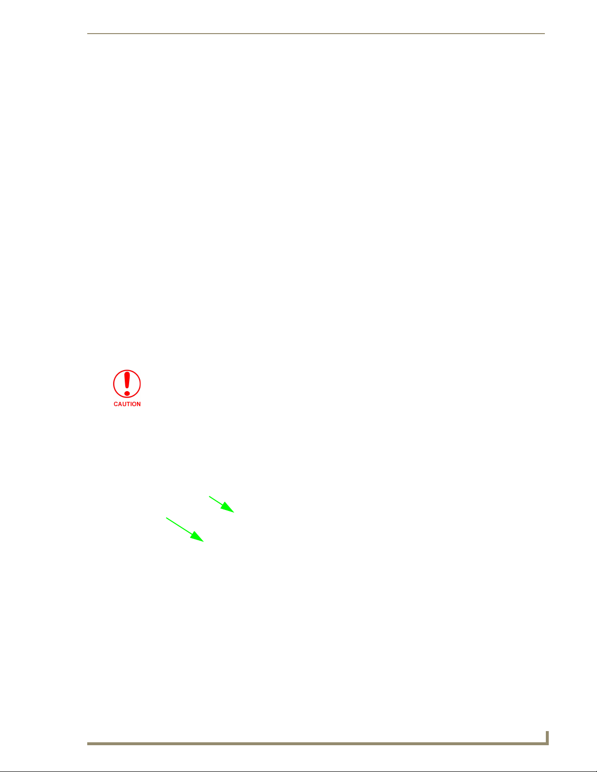
3. Open the support module case by pulling the cover straight forward, as shown in FIG. 25:
FIG. 25 Opening the support module case
4. Remove the circuit board from the base by pulling back the latch that holds it at the bottom center, as
shown in FIG. 26:
5. Use the sub-base as a template to mark the mounting hole locations on the wall. The word "TOP" is
written in the sub-base. Position the sub-base so that the wires can be pulled through the hole in the top
left-hand corner. Drill size for the wall anchors is 3/16 inch. Mount the
sub-base using the two #6 screws and anchors provided (larger screws will prevent the circuit board from
properly snapping into place).
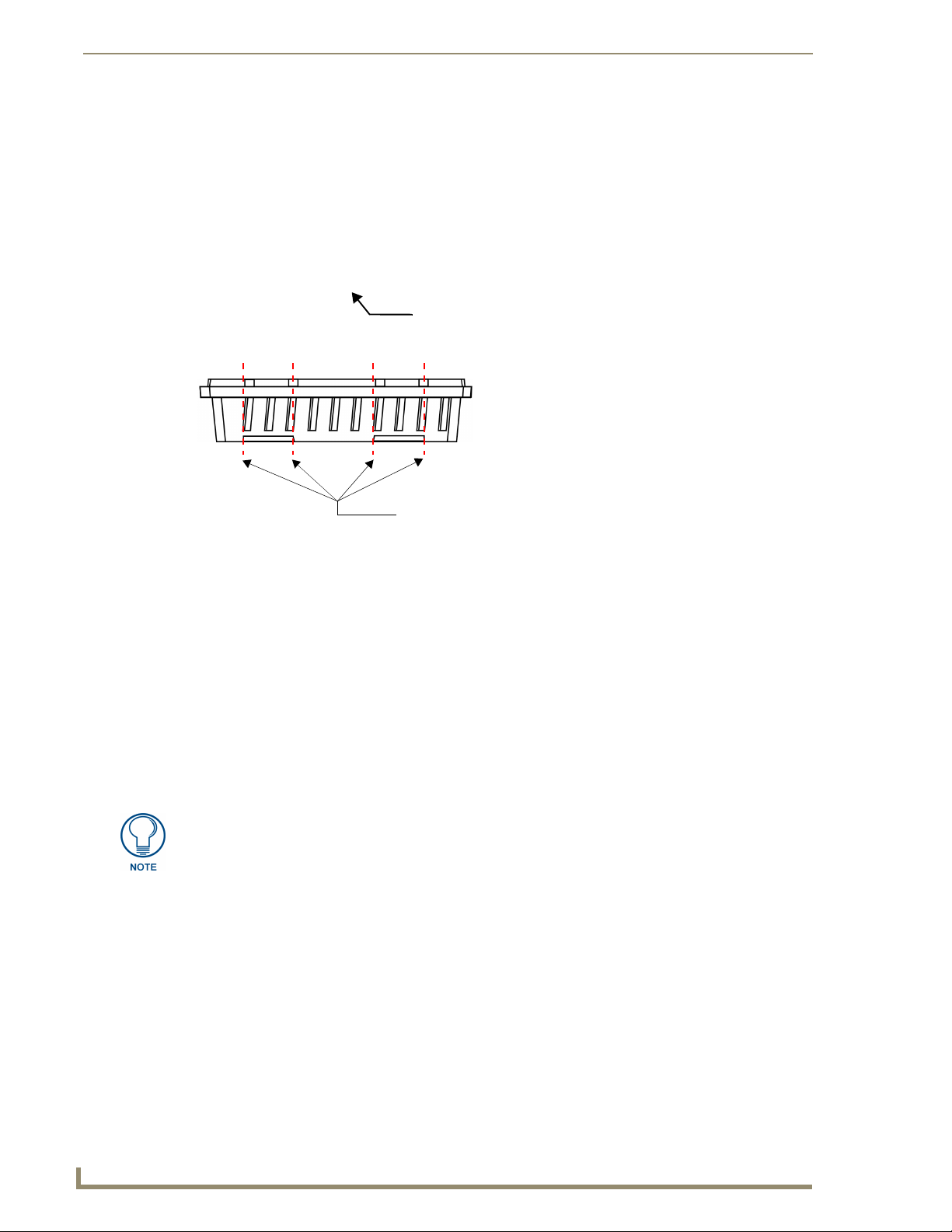
If side access is preferred for wiring, clip out the side vents on the scored lines (FIG. 27).
ViewStat Communicating Thermostat
33
Page 40
Support Module Installation and Wiring
FIG. 26 Removing the circuit board
Pull down
Cut here for access
FIG. 27 For side access, cut out the side vents on the scored lines.
6. Snap the circuit board back into the sub-base by sliding the top of the board in first and then snapping
down on the bottom. Check to be sure that the latch holds the board properly.
7. Strip ¼ inch of insulation from the four wires at the support module. Install the wires in the terminals
labeled RSR, RSC, RSB and RSA. One twisted pair of wires should be used for the RSR and RSC
connection and another pair of twisted wires should be used for the RSB and RSA connection. Push the
extra wire back into the wall cavity. Seal the hole in the wall around the cable to eliminate any draft that
might affect the sensor.
8. Connect the wires on the thermostat sub-base to the terminals labeled RSR, RSC, RSB and RSA on the
ViewStat base (see FIG. 5 on page 10) and the Communication and Equipment Terminal Wiring
Definitions table on page 20). Make sure that each terminal on the support module is wired to the
terminal with the same label at the thermostat.
9. If necessary, change the Support Module DIP switch settings as described in Setting the Support Module
DIP Switches section on page 35.
DIP switches must be set prior to powering the support module (support module is
powered when thermostat is returned to its base). If switches need to be changed
after powering the support module, the thermostat must be removed from its base for
a minimum of 15 seconds to ensure proper reset of the support module.
10. Mount the thermostat on the sub-base and confirm that it is displaying the right temperature from the
support module or remote sensor.
Multiple Support Module Installation
Up to 4 support modules can be connected to provide temperature or humidity averaging in a large area or for
several zones being controlled by the same system. The maximum cumulative distance of all the support
modules from the ViewStat is 1000 ft (304.8 m).
FIG. 28 shows daisy-chaining of the VST-TTM Remote Temperature and VST-TRH Remote Temperature/
Humidity Sensors.
34
ViewStat Communicating Thermostat
Page 41

Support Module Installation and Wiring
ViewStat (faceplate removed)
To other support modules
(maximum of 4 total)
VST-TTM or VST-TRH support modules
Flush-mount Indoor
VST-TSF
remote sensor
VST-TSO
Duct/Outdoor
remote sensor
FIG. 28 Daisy-chaining VST-TTM Remote Temperature and VST-TRH Remote Temperature/Humidity support modules
Always make sure that there is no power to the modules by removing the thermostat
from the sub-base.
1. Remove the thermostat from the sub-base.
2. Wire the first sensor using the single support module instructions. Daisy chain the remaining support
modules as shown below (FIG. 29).
Thermostat Module 1 Module 2 Module 3 Module 4
RSR
RSC
RSB
RSA
RSR RSR RSR
RSC RSC RSC
RSB RSB RSB
RSA RSA RSA
RSR
RSC
RSB
RSA
FIG. 29 Daisy-chaining support modules
3. Set the VST-TTM or VST-TRH Support Module DIP switches as described in the following Setting the
Support Module DIP Switches section.
4. Replace the thermostat on the sub-base. Check for proper operation of each sensor.
Setting the Support Module DIP Switches
Both the VST-TTM and VST-TRH support modules contain a 6-position DIP switch (FIG. 30) located on the
circuit board to set the support modules address, mode (monitor/control), and the temperature sensor source
(T1/T2 or Onboard Sensor). The ViewStat displays the temperature reading of whichever remote sensors are
connected to support modules in control mode. When multiple support modules are connected and in control
mode, the ViewStat displays an average of all incoming temperature readings. If all connected support
modules are set to monitor mode, then the ViewStat displays the temperature reading from the on-board
sensor, and the temperature from the remote sensor (or the average temperature if you’re using multiple
sensors) is displayed as the REMOTE temperature.
1
2
3
4
5
6
FIG. 30 VST-TTM or VST-TRH support module DIP switch
OFF ON
ADDRESS
ADDRESS
MONITOR (S1)
MONITOR (S2)
SPARE
T1/T2 (S1)
ADDRESS
ADDRESS
CONTROL (S1)
CONTROL (S2)
SPARE
ONBOARD SENSOR
ViewStat Communicating Thermostat
35
Page 42

Support Module Installation and Wiring
DIP switches 1 and 2: Address (1-4)
The following diagram shows how to set the top two address DIP switches. Each support module must have its
own address (1-4).
ADDRESS 1
ADDRESS 2
FIG. 31 Setting the top two address switches (switches 1 and 2)
ADDRESS 3
ADDRESS 4
DIP switch 3: Temperature Sensor 1
Each support module has two sensors: Sensor 1 and Sensor 2. Determine whether you want the Sensor 1 input
to monitor or control temperature. If DIP switch number 3 is in the "off " position, it will monitor the
temperature.
If the support module is set to Address 1 and the Sensor 1 input is set to "monitor",
then the monitored temperature will be displayed as the remote temperature in the
lower left hand corner of the thermostat. Otherwise, the monitored value will only be
available through the home automation system.
If DIP switch 3 is set to the "on" position, it will use the Sensor 1 temperature to control the thermostat. The
sensor control temperature will be displayed on the thermostat. If multiple sensors are daisy chained together,
all of the sensors set to control will be averaged and the average temperature will be displayed on the
thermostat.
Dip switch 4: Temperature Sensor 2 (VST-TTM support module only)
Sensor 2 is for an external flush-mount or outdoor/duct temperature sensor for the VST-TTM support module.
Determine whether you want the Sensor 2 input to monitor or control temperature. If DIP switch number 4 is
in the "off " position, it will monitor the temperature.
If DIP switch 4 is set to the "on" position, it will use the reported temperature to control the thermostat. The
sensor control temperature will be displayed on the thermostat. If multiple support modules are daisy chained
together, all of the sensors set to control will be averaged and the average temperature will be displayed on the
thermostat.
Dip switch 4: Humidity Sensor 2 (VST-TRH support module only)
Sensor 2 is for an onboard humidity sensor for the VST-TRH support module.
Determine whether you want the Sensor 2 input to monitor or control humidity. If DIP switch number 4 is in
the "off" position, it will monitor the humidity level (%).
If DIP switch 4 is set to the "on" position, it will control the humidity level and the value will be displayed on
the thermostat (with a % sign to indicate humidity). Up to 4 support modules can be daisy chained together.
All humidity sensors that are set to "Control" mode will be averaged and the average humidity will be
displayed on the thermostat.
If any of the remaining temperature sensors are also set to "control", the temperature
control averaging will override the humidity control averaging and humidity control
values will be ignored by the thermostat. To ensure that the thermostat recognizes
humidity control values, make sure that all temperature sensors (for this thermostat)
are set to the "Monitor" mode.
DIP switch 6: T1/T2 or Onboard Sensor
Determine whether you want the Sensor 1 input to use the temperature sensed by the onboard thermistor or to
use the input from a remote sensor (i.e. flush mount sensor or duct/outdoor sensor). If DIP switch number 6 is
in the "off" position it will use the remote sensor inputs (T1/T2). If the DIP switch is in the "on" position, it
will use the temperature input from the onboard thermistor. This option only exists for the Sensor 1 input and
can still be configured to monitor or control.
36
ViewStat Communicating Thermostat
Page 43

Support Module Installation and Wiring
The ViewStat will not display temperature or humidity (Sensor 1 or Sensor 2) values if
DIP switch 6 is set to T1/T2 without wiring a sensor to the T1/T2 terminal.
If a sensor is connected to the T1/T2 terminal; DIP switch 6 MUST be set to Off or an
invalid temperatures will be reported to the ViewStat.
Applications
Heat Pump Applications
If the support module is being used with a heat pump thermostat with auxiliary heat, the thermostat can be
configured to disable the use of auxiliary heat during warm weather and to lock out the compressor when the
outdoor temperature is too cold. This allows for the most efficient use of energy.
At warmer temperatures, a heat pump will operate much more efficiently than the auxiliary heat. It can save
energy to disable auxiliary heat in some cases, for example, when returning from a setback on a mild day. The
temperature above which auxiliary heat is disabled is the auxiliary lockout temperature or high balance point.
Refer to the thermostat user manual for a detailed explanation.
Air-to-air heat pumps become less efficient as the outdoor temperature drops. The temperature at which it
becomes more efficient to use auxiliary heat instead of the heat pump is the balance point or low balance point.
Configure the temperature sensor (T1/T2) that you are using to sense outdoor temperature to the "Monitor"
mode by setting the DIP switch 3 to the "off" position and the support module address to number 1. The high
and low balance points are set at the thermostat.
Humidity Control (VST-TRH only)
In order to set your thermostat up as a humidity controller, you will need at least one (up to four for averaging)
VST-TRH (temperature/humidity) support module(s) wired to the thermostat.
1. Locate the VST-TRH Support Module in the area that you want to control humidity.
2. Set the T3/T4 sensor (Humidity) Input to "Control" by moving the # 4 DIP switch to the "on" position.
Up to four T3/ T4 humidity sensors can be set to control and the reported values will be averaged and
displayed on the thermostat.
None of the temperature sensors connected to this ViewStat can be set to control
mode because a control temperature input to the ViewStat will override a control
humidity input. Make sure all temperature sensors connected to this ViewStat are set
to "Monitor".
3. Once the humidity control sensor(s) have been wired to the ViewStat, the thermostat display will change
to indicate % RH instead of °F/°C. The thermostat mode selections will also change to reflect humidity
control. The modes are "Humidify", "Dehumidify", "Humidify or Dehumidify" and "Off". Humidification/
Dehumidification set points are changed the same way that temperature control set points would be
changed.
Mode of Operation Set to "Humidify"
The B terminal is continually energized in the "Humidify" mode. When the thermostat calls for humidity, the
W1/HUM terminal will energize. If the minimum off time of 2 minutes has not elapsed since the previous call,
no terminals will energize until it has. All energized terminals will remain energized for the minimum on time
of 2 minutes.
Mode of Operation Set to "Dehumidify"
The O terminal is continually energized in the "Dehumidify" mode. When the thermostat calls for
dehumidification, the Y1/DEHUM terminal will energize. If the minimum off time of 4 minutes has not
elapsed since the previous call, no terminals will energize until it has. All energized terminals will remain
energized for the minimum on time of 4 minutes.
ViewStat Communicating Thermostat
37
Page 44

Support Module Installation and Wiring
Troubleshooting Remote Sensors
Thermostat has no display: Check 24 VAC supply. Check for incorrect wiring between the
thermostat and support module. Incorrect wiring can damage the thermostat and transformer or
blow a fuse in the equipment.
Also, verify that all support modules have a unique address.
Thermostat displays very high temperature or humidity: Ensure that DIP switch 6 is set
properly. If DIP switch 6 is set to T1/T2 and a sensor has not been wired to the T1/T2 terminal, no
temperature or humidity readings will be displayed. Also, if DIP switch 6 is set to onboard and a
remote sensor has been wired to the T1/T2 terminal, incorrect temperature readings will be
displayed. Check wires on remote sensors (flush mount or outdoor/duct) to ensure that they are not
touching. If they are, separate them.
Thermostat displays very low temperature: Remote sensor (flush mount or outdoor/duct) is not
connected to support module properly. Check wiring.
Thermostat doesn't display remote temperature/humidity: Make sure that the support module
is set to address 1. Reset support module after changing any DIP switches by turning off power for
approximately 15 seconds.
Thermostat displays RH instead of °F or °F instead of RH: Make sure that monitor/control DIP
switches are set correctly. Reset support module after changing any DIP switches by turning off
power for approximately 15 seconds.
38
ViewStat Communicating Thermostat
Page 45
Set Up and Configuration
The ViewStat has many features that can be adjusted to customize operations. Temperature Control Set Up,
Balance Point Set Up and Communications Set Up, in particular, should only be adjusted with the help of a
qualified service technician.
When first powered up, the Message Display will scroll through the current mode status, fan status, and
Heating/Cooling output status. This is referred to as Passive Display because you do not interact with it. To get
into the set-up menu, press the Enter and Mode buttons simultaneously.
Thermostat Set-Up is menu driven but only again, one menu item is visible at a time. FIG. 32 shows the entire
Main Menu. Selecting any one of the Main Menu items (by pressing the Enter button) will enter a
corresponding Sub-Menu. The Scroll Up and Scroll Down buttons are used to move between menu items or
change adjustable values. The Enter button is used to select a menu item or enter a value. When in Thermostat
Set-Up, if none of the three navigation buttons are pressed in 5 minutes, the display will return to Passive
Display.
Set Up and Configuration
Message display
Use to Scroll
Use to Select
Auto - 5 seconds
Network Override
Set Up Next
Thermostat
Lockout More
Security
Set Up More
Communications
Set Up More
Temperature
Set Up More
Backlight
Set Up More
Balance Points
Set Up More
Press
to enter User-Interactive display
+Press
to select a menu item or to enter a value
Use the Scroll Up and Scroll Down
buttons to move between menu items
and change values.
FIG. 32 Main Menu
The following items are configured in thermostat set-up:
ViewStat Communicating Thermostat
Display
Set Up
EXIT
More
Back
Select EXIT to return to the main menu from a
sub-menu.
Select EXIT to return to passive display from
the Main menu.
39
Page 46
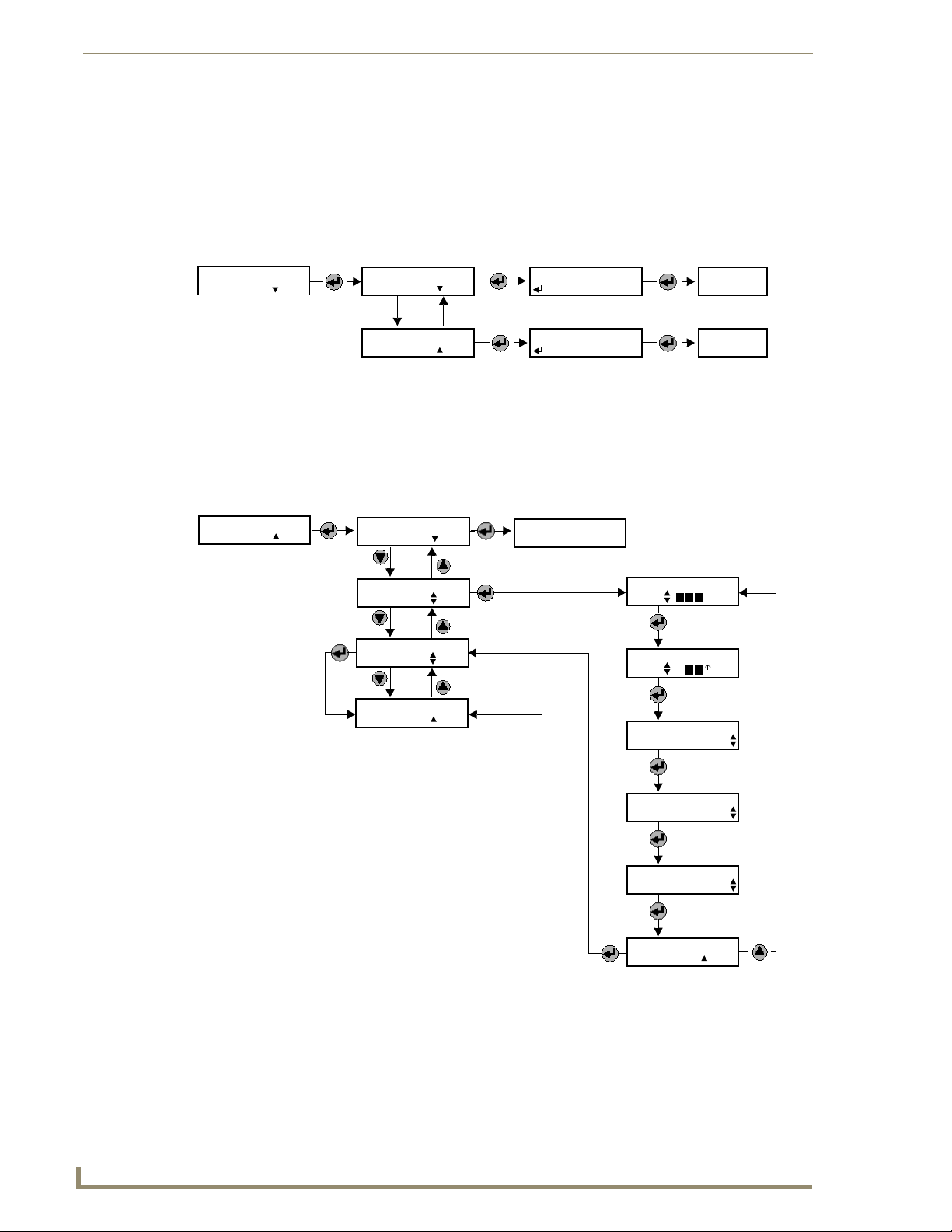
Set Up and Configuration
Network Override Set-Up
This enables or disables the Network Override feature. When Network Override has been invoked the
thermostat will only respond to the buttons of the thermostat; commands sent by the automation system are
ignored.
Pressing the Enter button activates Network Override. However, you can disable this feature if you don’t want
users to be able to activate Network Override. Enabling and Disabling of this feature is done through
Thermostat Set-Up (FIG. 33).
Network Override
Set Up Next
Enable Network
Override Next
Disable Network
Override Back
Net.Ovrd.Enabled
EXIT
Net.Ovrd.Disable
EXIT
MAIN MENU
MAIN MENU
FIG. 33 Network Override set-up
Thermostat Button Lockout
This feature partially or completely disables the buttons of the thermostat. For example, the MODE and FAN
status can be set and then locked, so the buttons will not allow those settings to be changed. Additionally, this
can be set to allow changes for a limited time and amount of change. For example, you can limit temperature
changes to ±3°, if desired (FIG. 34).
Thermostat
Lockout More
Complete
Lockout Next
Partial
Lockout More
Unlock
Thermostat More
EXIT
Back
SetPoints, Fan &
Mode Locked Out
Set Time Limit
Set Temp. Limit
Allow SetPoint
Changes? Timed
Allow Fan
Changes? Yes
+
-
min.
+
Time Val
-
Timed
Ye s
No
No
40
FIG. 34 Thermostat Button Lockout
Allow Mode
Changes? Yes
EXIT
Timed
Back
No
ViewStat Communicating Thermostat
Page 47

Set Up and Configuration
Security Set-Up
This prevents unauthorized individuals from accessing Thermostat Set-Up. A code can be setup that must be
entered to gain entry into Thermostat Set-Up (FIG. 35).
Security
Set Up More
Remove
Password Next
Set New Password
More
Enter Lockout
Code
ConfirmCode ####
change
EXIT
Back
accept
after 4th digit entered
after 4th digit entered
FIG. 35 Security set-up
FIG. 36 shows the display when a password has been activated, and entry into Thermostat Set-Up menu is
attempted..
The master key password is 7777.
Security is On
Enter Code
after successful
attempt
Code Accepted
auto - 5 sec.
go to
Main Menu
FIG. 36 Master key password
To reset the password to 7777, you must cycle power to the ViewStat.
An easy way to cycle power on the ViewStat without having to remove power from
the HVAC system is to remove the ViewStat faceplate from the base (see FIG. 2 and
FIG. 3 on page 8), then replace it.
ViewStat Communicating Thermostat
after unsuccessful
attempt
Code Incorrect
after 3rd unsuccessful
attempt
return to
Passive display
Auto - 5 sec.
after 1st and 2nd unsuccessful attempt
41
Page 48

Set Up and Configuration
Communications Set-Up
This is where the thermostat address is entered. Additionally, the total number of thermostats (or the highest
addressed stat on the network) is entered here to optimize communication timing. Consult a qualified service
technician before changing any of the values in this Sub-Menu (Sub-Menu not shown).
Temperature Set-Up
The first and second stage differentials can be changed, as can the display temperature offset. The differentials
set the tightness of the temperature control. If the equipment is operating too often, or the temperature swings
are uncomfortably large, the differentials can be increased or decreased respectively. The temperature offset
(calibration) allows the user to “customize” the temperature shown on the display. Consult a qualified HVAC
service technician before changing any of the values in this Sub-Menu (Sub-Menu not shown).
Temperature Control Options
OFFSET Allows the user to offset the displayed room temperature ±3°F from true tem-
1ST STAGE DIFFERENTIAL Determines the level of control and consequently the cycle rate. Adjustable
2ND STAGE DIFFERENTIAL Again adjustable between 0.5°F and 2.0°F, this also determines the level of
perature. This thermostat is calibrated to be within ±1°F of true temperature.
between 0.5°F and 2.0°F, this is the value above/below the set point that the
temperature must rise (fall) to start the cooling (heating). It is also the value
below (above) the set point that the temperature must fall (rise) for the cooling
(heating) to stop. For example, if the temperature setting was 70°F and the 1st
stage differential was set at 0.5°F, in the heat mode the heat would come on at
69.5°F and stay until the temperature was 70.5°F. A small differential will result
in a tighter control, but more heating/cooling cycles.
control by determining when to use the 2nd stage of heating or cooling. It can
also be used to keep 2nd stage cooling from coming on too soon when 1st
stage is acting to control temperature levels or to keep costly auxiliary heat
from coming on too soon when the heat pump is sufficient.
Backlighting Set-Up
Both displays have backlighting which can be controlled in three ways (FIG. 37). First, backlighting can be
turned on every time a button is pushed. Second, it can be configured to come on with a button push, but only
when the ambient light is below a preset value. When “only when needed” is selected, the user can select from
two levels of ambient light. Finally, it can be disabled.
42
ViewStat Communicating Thermostat
Page 49
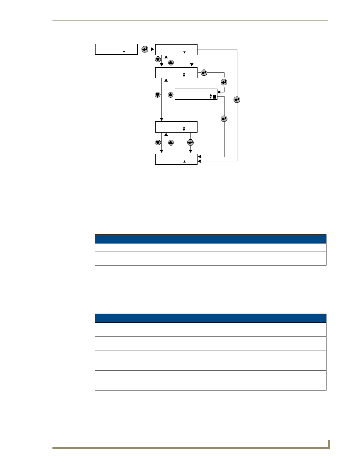
Set Up and Configuration
Backlight
Set Up More
FIG. 37 Backlighting set-up
On With Every
Change Next
On Only When
Needed
Disable
EXIT
More
Set, 1=lighter
2-darker
toggle between 1 and 2
using the Up and Down
buttons
More
Back
Balance Point Set-Up
Balance points limit heat pump operation when the outdoor temperature is too high or too low. It requires an
optional support module with an outdoor temperature sensor. Consult a qualified HVAC service technician
before changing any of the values in this Sub-Menu (Sub-Menu not shown).
These values are adjustable, but are only used by the thermostat when it has been configured to operate as a
heat pump, and when a remote outdoor temperature sensor (with address #1) is wired to the thermostat (see the
Heat Pump Applications section on page 37 for details).
Balance Point Options
LOW BALANCE POINT the outdoor temperature below which compressor terminals will not be energized.
HIGH BALANCE POINT the outdoor temperature above which the auxiliary heat terminal will not be ener-
gized in the HEAT mode (does not effect Emergency Heat operation).
Display Set-Up
Here the temperature scale can be changed to °C or °F, and the temperature settings can be setup to always
display or only when being changed (FIG. 38). The message display, when not being used for Thermostat SetUp will, by default, scroll through three messages showing the status of the mode, fan, and equipment output.
A fourth, date and time, can also be displayed in the scroll list.
Display Set-Up Options
TEMPERATURE SCALE all temperatures displayed including room temperatures and set points can be
SHOW TEMPERATURE SET
POINTS ALWAYS
SHOW TEMPERATURE SET
POINTS ONLY IF CHANGED
SHOW DATE AND TIME the message display will, by default, scroll three messages showing the status
°F or °C.
keeps the temperature settings visible on the display at all times.
displays the temperature settings (heat and/or cool) only when the user
changes them. The first press of either the up or down adjust buttons will display the settings.
of the mode, fan and equipment outputs. A fourth, date and time, can also be
displayed in the scroll list.
ViewStat Communicating Thermostat
43
Page 50

Set Up and Configuration
Display
Set Up More
FIG. 38 Display set-up
Temperature
Scale °F°C F
Show Temp Setpts
Always
Show Setpts Only
If Changed
Display Time and
Date?
EXIT
Next
More
Ye s
Back
44
ViewStat Communicating Thermostat
Page 51

Using the NetLinx Module to Program the ViewStat
Using the NetLinx Module to Program the
ViewStat
AMX_ViewStat NetLinx Module - Overview
The ViewStat Communicating Thermostat may be controlled from a NetLinx system using the AMX_ViewStat
NetLinx module. This module requires ViewStats to be connected through an ICSNet interface.
The ViewStat module is designed to save you the work of manually coding the entire ViewStat command set.
By using the module, you’ll save time, and still take full advantage of the ViewStat’s features. While it is
strongly recommended that you use the NetLinx module, it is also possible to write your own code "from
scratch".
For a detailed description of the NetLinx programming protocol for the ViewStat, refer
to the "ViewStat Programming Protocol Reference Manual", available on the
AMX.COM web site.
When connecting thermostats (thermostat/mini-verter pair), it is best to initialize each mini-verter separately.
If all mini-verter devices have the same device number and are on the bus at the same time, an initialization
problem can occur where all devices obtain the same new device identification number. This is different from
the serial number of the thermostat that is set locally at the thermostat.
The ViewStat may be controlled from a NetLinx system using the AMX_ViewStat NetLinx module. This
module requires ViewStats to be connected through an ICSNet interface. The number of thermostats is limited
by the number of ICSNet devices that may be connected at one time to the master. The initialization sequence
is shown below.
DEFINE_DEVICE
VST = 34001:1:0
VST_1 = 1:1:0
VST_2 = 2:1:0
VST_OPS = 33001:1:0
DEFINE_VARIABLE
VST_ZoneCnt = 1
Scale = 1
dev VSTArry[] =
{
VST_1,
VST_2
}
integer VSTStatNum[] =
{
1,
1
}
DEFINE_MODULE 'AMX_VST' myVST (VSTArry, VST_OPS, VSTStatNum, VST_ZoneCnt, Scale)
ViewStat Communicating Thermostat
45
Page 52
Using the NetLinx Module to Program the ViewStat
It is important that the serial number array be the same length as the device array. If the serial number array
happens to be shorter, the length will be set to that of the device array and the new members of the array will be
set to the value 1. The two arrays are used to associate the ICSNet device number to the stat number of the
thermostats (set locally through the thermostat's user interface)
Upon initialization, the VST module will retrieve the current settings of all of the thermostats on the network.
This operation may take several seconds. During this time the NetLinx program will start receiving strings
representing the states of all of the thermostat's controls. The above default temperature scale is Fahrenheit.
The ViewStat Communicating Thermostat is an enhanced version of the OPStat with the communication board
built into the thermostat, advanced features and two displays. One display is for temperature, mode, limit
settings, lock status, fan status, network communication and humidity. The second display is used for general
text messaging for date, time, event status, and setup mode and user notifications.
The ViewStat can monitor remote temperature and humidity, has a flexible text mode setup and interface, and
has the ability to lock local control of the thermostat.
Care must be taken when attaching to remote sensors in that the remotes can turn the thermostat into a
humidity sensor that doesn't display the temperature in the main window. When acting as a humidity sensor,
the temperature can be retrieved through the control interface only. The remote temperature is displayed in
minor sections of the main window while the remote humidity inhabits the window center. When a remote
sensor is attached, humidity changes do not generate a Change Of State message. Also, as a humidity sensor,
the mode button will change from humidity to dehumidify and report accordingly over the control interface. To
retrieve humidity, there is a conditional poll generated upon temperature events if the temperature event came
from a humidity-supported device.
The VST_ZoneCnt is used to affect the wait period between successive commands being sent to the
thermostats. The larger the VST_ZoneCnt value is, the longer the time delay between global commands
becomes. The VST_ZoneCnt variable is associated with the serial number of a thermostat.
To install the ViewStat module, the developer must create an array of devices and an array of integers that
stand for the serial number of the thermostat corresponding to the physical ICSNet device. Unless otherwise
needed, the serial number of all thermostats should be set to '1', to allow the quickest response from the
thermostat on global commands.
ViewStat also provides feedback from its local buttons: enter, scroll up, and scroll down. This allows the
control system to track the menu navigation if desired.
The following diagram gives a graphical view of the interface between the NetLinx program and the NetLinx
module.
46
NetLinx
Program
FIG. 39 Interface between the NetLinx program and the NetLinx module.
Virtual
Device
NetLinx
Module
ViewStat
Controller
The ViewStat Model
The model will define a security system as consisting of the following components:
1. System: This refers the controller and all that it controls.
2. Zone: The system will consist of one or more ViewStat zones. A zone is nothing more than an area that
can be controlled separate from other areas. Zones have their own temperature settings.
3. Thermostat: Each zone contains a thermostat. The thermostat is used for reading temperature and
controlling when to turn on/off equipment as needed to maintain the desired temperature setting.
Thermostats can control fans, heat, A/C., etc.
4. Setpoint: There are two types of setpoints: heat and cool. When the temperature reaches or falls below
the heat setpoint the thermostat will turn the heat on (call for heat). When the temperature reaches or
exceeds the cool setpoint the thermostat will turn the air conditioner on (call for air). These are also called
comfort points. A user can keep the temperature within these points at all times by setting the setpoint
values. For example, to maintain a temperature of 68-72 degrees the heat setpoint would be set to 68, the
ViewStat Communicating Thermostat
Page 53

Using the NetLinx Module to Program the ViewStat
cool setpoint would be set to 72. While the temperature is within this range nothing is done. Once the
temperature falls outside this range the system takes action and switches to the appropriate mode.
5. Humidify/Dehumidify: Some systems can maintain the humidity level within a certain range. These are
similar to temperature setpoints except instead of temperature control equipment the system is controlling
humidify and dehumidify equipment.
Command Interface - SEND_COMMANDs
Various system wide operations may be performed by the NetLinx program via SEND_COMMANDs sent to
the virtual device controlling the thermostats.
The supported commands are listed below.
Command Interface - SEND_COMMANDs
Command Description
'T-<tstat> COOL-<val>' Set cool set point.
Parameters:
• <tstat> : id of thermostat/zone
•<val>:
+ = increase cool set point by one degree
- = Decrease cool set point by one degree
60-108 = new cool set point (F)
Examples:
'T-4 COOL--'
'T-1 COOL-76'
'T-<stat> COOL?' Query for current cool set point.
Parameter:
• <tstat>: id of thermostat/zone
Example:
'T-16 COOL?'
'T-<tstat> DATE-<val>' Set date.
Parameters:
• <tstat> : id of thermostat/zone
• <val> : MMDDYY
Example:
'T-1 DATE-030894'
'T-<tstat> DATE?' Requests current date on thermostat
'T-<tstat> DEHUMIDIFY-<val>' Set dehumidify set point.
Parameters:
<tstat> : id of thermostat/zone
<val>:
+ = Increase dehumidify set point by one percent
- = Decrease dehumidify set point by one percent
10-90 = dehumidify set point (in percent)
Example:
'T-6 DEHUMIDIFY-70'
'T-<stat> DEHUMIDIFY?' Query for current dehumidify set point.
Parameter:
• <tstat> : id of thermostat/zone
Example:
'T-1 DEHUMIDIFY?'
ViewStat Communicating Thermostat
47
Page 54

Using the NetLinx Module to Program the ViewStat
Command Interface - SEND_COMMANDs (Cont.)
Command Description
'T-<stat> FAN?' Query for current fan state.
'T-<tstat> FMODE-<val>' Set fan mode.
'T-<stat> FMODE?' Query for current fan mode.
'T-<tstat> HEAT-<val>' Set heat set point.
'T-<stat> HEAT?' Query for current heat set point.
'T-<tstat> HMODE-<val>' Set humidify mode.
Parameter:
• <tstat> : id of thermostat/zone
Example:
'T-2 FAN?'
Parameters:
• <tstat> : id of thermostat/zone
• <val> : 0 = let thermostat control the fan
1 = turn fan on
T = toggle fan mode
Example:
'T-12 FMODE-AUTO'
Parameter:
• <tstat> : id of thermostat/zone
Example:
'T-2 FMODE?'
Parameters:
• <tstat> : id of thermostat/zone
•<val> :
+ = increase heat set point by one degree
- = decrease heat set point by one degree
38..88 = new heat set point (F)
Examples:
'T-1 HEAT-+'
'T-1 HEAT-68'
Parameter:
• <tstat> : id of thermostat/zone
Example:
'T-4 HEAT?'
Parameters:
• <tstat> : id of thermostat/zone
•<val>:
OFF = disable (no humidity control)
HUMID = enter humidify mode
DEHUM = enter dehumidify mode
AUTO = automatically control humidity based on humidify
and dehumidify set points.
T = toggle humidify mode
Example:
'T-6 HMODE-AUTO'
48
ViewStat Communicating Thermostat
Page 55

Using the NetLinx Module to Program the ViewStat
Command Interface - SEND_COMMANDs (Cont.)
Command Description
'T-<stat> HMODE?' Query for current humidify mode.
Parameter:
• <tstat> : id of thermostat/zone
Example:
'T-22 HMODE?'
'T-<tstat> HOLD-<val>' Set thermostat hold state.
Parameters:
• <tstat> : id of thermostat/zone
•<val>:
0 = take thermostat out of hold mode
1 = place thermostat in hold mode
T = toggle hold state
Example:
'T-2 HOLD-ON'
'T-<stat> HOLD?' Query for current hold state.
Parameter:
• <tstat> : id of thermostat/zone
Example:
'T-1 HOLD?'
'T-<tstat> HUMIDIFY-<val>' Set humidify set point.
Parameters:
• <tstat> : id of thermostat/zone
•<val>:
+ = Increase humidify set point by one percent
- = Decrease heat set point by one percent
10-90 = humidify point (in percent)
Example:
'T-6 HUMIDIFY-30'
'T-<stat> HUMIDIFY?' Query for current humidify set point.
Parameter:
• <tstat> : id of thermostat/zone
Example:
'T-1 HUMIDIFY?'
'T-<tstat> HUM?' Query for current inside humidity.
Parameter:
• <tstat> : id of thermostat/zone
Example:
'T-14 HUM?'
'T-<tstat> ID?' Get thermostat identification number.
ViewStat Communicating Thermostat
49
Page 56
Using the NetLinx Module to Program the ViewStat
Command Interface - SEND_COMMANDs (Cont.)
Command Description
'T-<tstat> LIGHT-<val>' Control backlight on thermostat.
'T-<tstat> LOCK-<val>' Set thermostat lock state.
'T-<stat> LOCK?' Query for current lock state.
'T-<tstat> MENU-<val>' When on, displays text as set by the MSG command.
'T-<tstat> MENU?' Gets the current menu state
'T-<tstat> MODE-<val>' Set HVAC mode.
'T-<stat> MODE?' Query for current HVAC mode.
Parameters:
• <tstat> : id of thermostat/zone
• <val> :
0 = off
1 = on
T = toggle
Example:
'T-1 LIGHT-T'
Parameters:
• <tstat> : id of thermostat/zone
•<val> :
0 = unlock thermostat
1 = lock thermostat
T = toggle lock state
Example:
'T-2 LOCK-ON'
Parameter:
• <tstat> : id of thermostat/zone
Example:
'T-10 LOCK?'
Parameters:
• <tstat> : id of thermostat/zone
•<val> :
1 = enables display of 'msg' message
0 = disables display of 'msg' message
Parameters:
• <tstat>: id of thermostat/zone
•<val>:
OFF = disable (no cool, no heat)
HEAT = enter heat mode (no cool)
COOL = enter cool mode (no heat)
AUTO = let thermostat control heat and cool based on set
points.
T = toggle HVAC mode
Example:
'T-6 MODE-AUTO'
Parameter:
• <tstat> : id of thermostat/zone
Example:
'T-1 MODE?'
50
ViewStat Communicating Thermostat
Page 57

Using the NetLinx Module to Program the ViewStat
Command Interface - SEND_COMMANDs (Cont.)
Command Description
'T-<tstat> MSG-<text>' Displays text on thermostat window when MENU is enabled.
'T-<tstat> OUTHUM?' Query for current outside humidity.
Parameter:
• <tstat> : id of thermostat/zone
Example:
'T-14 OUTHUM?'
'T-<tstat> OUTTEMP?' Query for current outside temperature.
Parameter:
• <tstat> : id of thermostat/zone
Example:
'T-2 OUTTEMP?'
'T-<tstat> PASSTHRU-<data>' Send data to thermostat with no processing by the module.
'T-<tstat> TEMP?' Query for current inside temperature.
'T-<tstat> TIME-<val>' Set time.
'T-<tstat> TIME?' Requests current time on thermostat.
'T-<tstat> TXT-<line>,<val>' Set text message to be displayed in rolling message.
'T-<tstat> TXT?<line>' Read text to be displayed on thermostat.
The user can use this to send commands directly to the thermostat.
Parameters:
• <tstat>: id of thermostat/zone
• <data> : data to send to thermostat
Example:
'T-1 PASSTHRU-SOME COMMAND TO SEND'
Parameter:
• <tstat> : id of thermostat/zone
Example:
'T-4 TEMP?'
Parameters:
• <tstat> : id of thermostat/zone
• <val>: HHMMSS (24-hour clock)
Example:
'T-1 TIME-163248'
Parameters:
• <tstat> : id of thermostat/zone
• <line>: 1-4 = message number to be set
• <val> : string of text
Example:
'T-8 MSG-1,Hello World!'
Parameters:
• <tstat> : id of thermostat/zone
• <line>: 1-4 = message number to read
• <val> : string of text
Example:
'T-8 MSG-1,Hello World!'
ViewStat Communicating Thermostat
51
Page 58

Using the NetLinx Module to Program the ViewStat
Command Interface - SEND_COMMANDs (Cont.)
Command Description
'SCALE-<val>' Global command to set the temperature scale.
'SCALE?' Query for the current temperature scale.
'USEDEBUG-<val>' Global command to enable the sending of debug data to
'USEDEBUG?' Query for the current debug state.
'VERSION?' Query for the current version number of the NetLinx module.
Parameter:
•<val> :
C = Celsius
F = Fahrenheit (default)
Example:
'SCALE-F'
Example:
'SCALE?'
device 0.
Parameter:
•<val>:
1 = enables
0 = disables
Example:
'VERSION?'
String Feedback
The NetLinx module will provide feedback to the glue code for ViewStat system changes via string events.
Below are the strings supported. Data coming from the module will be in the form of strings. Data going to the
module will be in the form of commands.
String Feedback
String Description
'T-<tstat> COOL-<val>' Reports current cool set point.
Parameters:
• <tstat> : id of thermostat/zone
• <val> : 60..108 = new cool set point (F)
Example:
'T-1 COOL-76'
'T-<stat> DATE-<val>' Reports thermostat date.
Parameter:
• <val>: MMDDYY, 062102 = (June 21, 2002)
'T-<tstat> DEHUMIDIFY-<val>' Reports current dehumidify set point.
Parameters:
• <tstat> : id of thermostat/zone
• <val> : 2-99 = dehumidify set point (in percent)
Example:
'T-6 DEHUMIDIFY-70'
52
ViewStat Communicating Thermostat
Page 59

Using the NetLinx Module to Program the ViewStat
String Feedback (Cont.)
String Description
'T-<stat> FAN-<val>' Reports current fan state.
Parameters:
• <tstat> : id of thermostat/zone
• <val> :
0 = fan is off
1 = fan is on
Example:
'T-2 FAN-1'
'T-<tstat> FMODE-<val>' Reports current fan mode.
Parameters:
<tstat> : id of thermostat/zone
<val> : ON = fan on
AUTO = thermostat will control the fan
Example:
'T-12 FMODE-AUTO'
'T-<tstat> HEAT-<val>' Reports current heat set point.
Parameters:
• <tstat> : id of thermostat/zone
• <val> : 38..88 = current heat set point (F)
Example:
'T-1 HEAT-68'
'T-<tstat> HMODE-<val>' Reports current humidify mode.
Parameters:
• <tstat> : id of thermostat/zone
• <val> :
OFF = disabled (no humidity control)
HUMID = humidify mode
DEHUM = dehumidify mode
AUTO = automatically controlled based on humidify and
dehumidify set points.
Example:
'T-6 HMODE-AUTO'
'T-<tstat> HOLD-<val>' Reports current thermostat hold state.
Parameters:
• <tstat> : id of thermostat/zone
• <val> :
ON = thermostat in hold mode
OFF = thermostat no in hold mode
Example:
'T-2 HOLD-ON'
'T-<tstat> HUM-<val>' Reports current inside humidity.
Parameters:
• <tstat> : id of thermostat/zone
• <val> : 0..100 = humidity level (%)
Example:
'T-14 HUM-56'
ViewStat Communicating Thermostat
53
Page 60
Using the NetLinx Module to Program the ViewStat
String Feedback (Cont.)
String Description
'T-<tstat> HUMIDIFY-val>' Reports current humidify set point.
'T-<stat> ID-<val>' Reports identification number of thermostat.
'T-<tstat> LOCK-<val>' Reports current thermostat lock state.
'T-<stat> MENU-<val>' Reports Menu state, ON/OFF.
'T-<tstat> MODE-<val>' Reports current HVAC mode.
'T-<tstat> OUTHUM-<val>' Query for current outside humidity.
'T-<tstat> OUTTEMP-<val>' Reports current outside temperature.
'T-<stat> PMES<num>-<val>' Reports scrolling message.
Parameters:
<tstat> : id of thermostat/zone
<val> : 0-97 = humidify point (in percent)
Example:
'T-6 HUMIDIFY-30'
Parameters:
• <tstat> : id of thermostat/zone
• <val> :
ON = thermostat is locked
OFF = thermostat is unlocked
Example:
'T-2 LOCK-ON'
Parameters:
• <tstat> : id of thermostat/zone
• <val> :
OFF = disabled (no cool, no heat)
HEAT = heat mode (no cool)
COOL = cool mode (no heat)
AUTO = thermostat automatically controls heat and cool
based on set points.
Example:
'T-6 MODE-AUTO'
Parameters:
• <tstat> : id of thermostat/zone
• <val> : 0..100 = humidity level (%)
Example:
'T-8 OUTHUM-68'
Parameters:
• <tstat> : id of thermostat/zone
• <val> : current outside temperature
Example:
'T-2 OUTTEMP-84'
Parameters:
• <num>: message 1-4
• <val>: data that message happens to be
54
ViewStat Communicating Thermostat
Page 61

Using the NetLinx Module to Program the ViewStat
String Feedback (Cont.)
String Description
'T-<tstat> TEMP-<val>' Reports current inside temperature.
Parameters:
• <tstat> : id of thermostat/zone
• <val> : current inside temperature
Example:
'T-4 TEMP-76'
'T-<stat> TIME-<val>' Reports thermostat time.
Parameter:
• <val>: HHMM, 1630 = (4:30 p.m.)
'T-<tstat> TXT-<line>,<val>' Reports the text to be displayed for that message.
Parameters:
• <tstat> : id of thermostat/zone
• <line>: 1-4 = message number
• <val> : string of text
Example:
'T-2 MSG-2, 'Went shopping''
'SCALE-<val>' Reports current temperature scale.
Parameter:
•<val> :
C = Celsius
F = Fahrenheit (default)
Example:
'SCALE-F'
'USEDEBUG-<val>' Displays debug state.
Parameter:
•<data> :
1 = enabled
0 = disabled
'VERSION=xx.yy' Reports current version number of the NetLinx module.
Example:
'VERSION=2.46'
ViewStat Communicating Thermostat
55
Page 62

Using the NetLinx Module to Program the ViewStat
56
ViewStat Communicating Thermostat
Page 63

Operating the Thermostat
M
This section describes the front panel components, and gives instructions for operating the ViewStat
thermostat. FIG. 40 shows the front panel.
Front Panel Components
Message Display
Two types of messages are displayed, Permanent and Te m po r ar y Messages. Permanent Messages are those
that scroll continually during thermostat operation. Temporary (flashing) Messages are intended to catch your
eye and must be reset to be removed from the display. Thermostats are shipped with default (permanent) status
messages (i.e. mode status, fan status, equipment status).
Operating the Thermostat
essage display
Scroll/Setup buttons
Main display
Mode button
Adjust buttons
FIG. 40 ViewStat Thermostat (front panel)
Enter button
Fan button
Scroll/Set-up buttons
The Scroll/Set-Up buttons function with the set-up features of the thermostat (refer to the Set Up and
Configuration section on page 39 for details).
Mode button
Five modes of operation are available on the ViewStat thermostat:
OFF
COOL
AUTO
HEAT
EM. HEAT (for heat pumps only)
The mode of operation indicates how you want your heating and cooling equipment to operate.
Adjust buttons
The Adjust buttons adjust the heating and cooling temperature settings.
ViewStat Communicating Thermostat
57
Page 64

Operating the Thermostat
Fan button
The fan can be operated continuously (FAN ON) or only when there is a need to heat or cool.
Enter button
The Enter (or Network Override) button is used to override the home automation system, to clear temporary
flashing messages on the message display and with the set-up features of the thermostat.
Main display
The Main display (FIG. 41) provides the mode status, temperature and system status information.
Network Status
Network Override
Remote Temperature/
Relative Humidity
FIG. 41 Main Display window
Room Temperature/
Relative Humidity
Lockout
Fan Status
Set Points
Mode Status
The following table describes the items on the Main display:
Main Display
MODE STATUS Shows the current mode of operation: OFF, COOL, HEAT or COOL, EM. HEAT
SET POINTS Shows the Heating and/or Cooling temperature settings.
FAN STATUS FAN ON indicates the fan is set to operate continuously.
LOCKOUT The lockout setting shows the thermostat buttons have been locked out and the
ROOM TEMPERATURE Shows the current room temperature. The temperature can be displayed in °F or
REMOTE TEMPERATURE/
RELATIVE HUMIDITY
NETWORK OVERRIDE When NETWORK OVERRIDE is displayed, the thermostat has been taken off-
NETWORK STATUS This computer icon shows the thermostat is connected to the system. The icon
(for heat pumps only), and HEAT. The current mode will flash to show when the
equipment is running.
thermostat settings can not be changed at the thermostat.
°C. This would show relative humidity (%) if the thermostat has been installed
with an optional humidity control sensor.
A temperature and/or a relative humidity value will be displayed alternately here
when an optional remote temperature and/or humidity sensor has been installed
(typical use is for outdoor temperature).
line from the system. The thermostat can then only be operated at the
thermostat.
will flash when the thermostat sends or receives information. If there is no
activity on the system for 15 minutes the icon will be crossed out. This does not
mean the thermostat is unable to communicate, only that there has been no
communication to this thermostat in 15 minutes.
58
ViewStat Communicating Thermostat
Page 65

Operating the Thermostat
Operating The Thermostat
Notes on temperature adjustments:
The COOL setting must always be a minimum of 2° (F or C) higher than the HEAT setting. The
thermostat will automatically maintain the 2° difference. For example, if the Cooling set point is
75°F and one changes the Heating set point to 74°F, the thermostat will automatically change the
Cooling set point to 76°F.
The lockout icon will appear on the display when attempting to make a change, if the thermostat
has been configured to be locked out or the desired change violates the thermostat limits (i.e. lowest
allowable HEAT setting is 40°F, highest allowable COOL setting is 90°F, etc.). Lockout
configuration can be altered in set-up menu (see the Thermostat Button Lockout section on
page 40).
Selecting the Mode
The thermostat can be set to OFF, COOL, HEAT or COOL (auto-changeover), EM. HEAT (for heat pumps
only), and HEAT modes. To set, press the Mode button until the desired mode appears on the display
(FIG. 42).
Off Cool
HEAT COO L EM. H EAT
Heat or Cool Emergency Heat
HEAT
Heat
FIG. 42 Mode messages
The following table describes each of the modes:
• OFF Select the OFF mode to prevent the heating and cooling equipment
• COOL COOL appears on the display and only the cooling equipment will be
• HEAT HEAT appears on the display and only the heating equipment will be
• AUTO (heat or cool
auto-changeover)
• EMERGENCY HEAT
(EM. HEAT for heat pump
equipment only)
from operating.
operated to maintain the temperature at the COOL setting. COOL
will flash on the main display when the cooling equipment is
operating.
operated to maintain the temperature at the HEAT setting. HEAT will
flash on the main display when the heating equipment is operating.
HEAT or COOL appears on the display. Either the heating or cooling
equipment will operate to maintain the room temperature at or above
the HEAT setting and at or below the COOL setting. HEAT or COOL
will flash when the respective equipment is operating.
EM. HEAT appears on the display and only the back-up heat source
will be operated to maintain the room temperature above the HEAT
setting. This is generally more expensive than using the heat pump
(HEAT MODE), so use accordingly. Typical usage is when the heat
pump has malfunctioned.
ViewStat Communicating Thermostat
59
Page 66

Operating the Thermostat
–
Do not set the thermostat to OFF mode during periods when freezing temperatures
could occur.
Setting temperatures
Press the Up or Down adjust button. The setting to be changed will begin to flash. Press and hold the button
to change the setting.
Fan operation
The thermostat can operate the fan either continually (FAN ON), or only during Heating and Cooling calls.
Press the Fan button to toggle between these two options. FAN ON is recommended for media/electronic air
cleaners, ventilating equipment, and to allow for humidification in mild climates.
If operating in the HEAT mode, the only temperature set point available to change is the Heat
setting. When the room temperature drops below this setting the heat will come on (call for
heating) to raise the temperature. EM. HEAT mode uses the HEAT setting.
If operating in the COOL mode, the only temperature set point available to change is the COOL
setting. When the room temperature rises above this setting the Cooling will come on (call for
cooling) to lower the temperature.
If operating in AUTO (HEAT or COOL) mode, the first press of the Up or Down adjust button will
indicate which of the two temperature settings will be adjusted – it will be the one flashing.
If this is not the desired temperature to adjust, press the Mode button to access the other
temperature setting.
Backlight operation
Operation of the backlight is configured in the Thermostat Set-Up. Depending on the set-up, the backlight will
light at the press of any button, or it can be disabled (see theBacklighting Set-Up section on page 42). The
backlight will stay on for 10 seconds after the last press of a button.
Network override
If the Network Override has not been disabled in the Thermostat Set-Up, the Network Override can be
initiated by pressing the Enter button. When initiated, the thermostat is taken offline from the automation
system. The thermostat can then only be operated at the thermostat. Pressing the Enter button again will
restore network communication.
Clearing a temporary flashing message
Custom Home Automation systems have the ability to send a temporary message to the message display. This
message will flash until the user acknowledges the message. To acknowledge message press the Enter button.
In Case Of Power Failure
This thermostat does not require a battery. If the power goes out, the screen is blank. During the period the
power is off, the heating/cooling system will not operate. When power is restored, the thermostat will return to
the previous settings. The thermostat is equipped with a continuous memory feature which does not require a
battery.
Cleaning the Thermostat
If the surface of the thermostat becomes dirty it can be cleaned with plain water or with a non-abrasive
household cleaner, including glass cleaner. When using any cleaner be careful not to get any into the interior of
the thermostat. Do not spray any liquid directly onto the thermostat. Spray the cleaner onto a soft cloth and
wipe the surface of the thermostat.
60
ViewStat Communicating Thermostat
Page 67

Operating the Thermostat
ViewStat Communicating Thermostat
61
Page 68

It’s Your World - Take Control™
3000 RESEARCH DRIVE, RICHARDSON, TX 75082 USA • 800.222.0193 • 469.624.8000 • 469-624-7153 fax • 800.932.6993 technical support • www.amx.com
2008 AMX. All rights reserved. AMX and the AMX logo are registered trademarks of AMX. AMX reserves the right to alter specifications without notice at any time.
©
5/08
 Loading...