

Page 1

Operation/Reference Guide
UDM-1604
Endeleo Multi-Format Distribution Hub
Endeleo Distributed Media
Last Updated: 1/24/2008
Page 2

AMX Limited Warranty and Disclaimer
All products returned to AMX require a Return Material Authorization (RMA) number. The RMA number is
obtained from the AMX RMA Department. The RMA number must be clearly marked on the outside of each
box. The RMA is valid for a 30-day period. After the 30-day period the RMA will be cancelled. Any shipments
received not consistent with the RMA, or after the RMA is cancelled, will be refused. AMX is not responsible
for products returned without a valid RMA number.
Warranty Repair Policy
• AMX will repair any defect due to material or workmanship issues during the applicable warranty period at no cost to the AMX
Authorized Partner., provided that the AMX Authorized Partner is responsible for in-bound freight and AMX is responsible for
out-bound ground freight expenses.
• The AMX Authorized Partner must contact AMX Technical Support to validate the failure before pursuing this service.
• AMX will complete the repair and ship the product within five (5) business days after receipt of the product by AMX. The AMX
Authorized Partner will be notified if repair cannot be completed within five (5) business days.
• Products repaired will carry a ninety (90) day warranty or the balance of the remaining warranty, whichever is greater.
• Products that are returned and exhibit signs of damage or unauthorized use will be processed under the Non-Warranty Repair
Policy.
• AMX will continue to provide Warranty Repair Services for products discontinued or replaced by a Product Discontinuance
Notice.
Non-Warranty Repair Policy
• Products that do not qualify to be repaired under the Warranty Repair Policy due to age of the product or Condition of the product may be repaired utilizing this service.
• The AMX Authorized Partner must contact AMX Technical Support to validate the failure before pursuing this service.
• Non-warranty repair is a billable service.
• Products repaired under this policy will carry a ninety (90) day warranty on material and labor.
• AMX will notify the AMX Authorized Partner with the cost of repair, if cost is greater than the Standard Repair Fee, within five (5)
days of receipt.
• The AMX Authorized Partner must provide a Purchase Order or credit card number within five (5) days of notification, or the
product will be returned to the AMX Authorized Partner.
• The AMX Authorized Partner will be responsible for in-bound and out-bound freight expenses.
• Products will be repaired within ten (10) business days after AMX Authorized Partner approval is obtained.
• Non-repairable products will be returned to the AMX Authorized Partner with an explanation.
• See AMX Non-Warranty Repair Price List for minimum and Standard Repair Fees and policies.
Page 3

Page 4

Page 5

Table of Contents
Table of Contents
Important Safety Markings .................................................................................1
Markings Used In This Manual .................................................................................. 1
Voltage............................................................................................................................ 1
Rating Label.............................................................................................................. 1
Important Instructions .............................................................................................. 2
Compliance ............................................................................................................... 2
FCC and IEC .................................................................................................................... 2
Date of Manufacture ....................................................................................................... 2
Environmental Conditions......................................................................................... 3
Temperature ................................................................................................................... 3
Humidity.......................................................................................................................... 3
Water / Liquids................................................................................................................ 3
External use .................................................................................................................... 3
UDM-1604 Multi-Format Distribution Hub .........................................................1
Overview .................................................................................................................. 1
Features.................................................................................................................... 1
Compatibility ............................................................................................................ 2
Product Specifications ............................................................................................. 2
Installation ..........................................................................................................5
Overview .................................................................................................................. 5
Ventilation....................................................................................................................... 5
Wiring and Connections .....................................................................................7
UDM-1604 Front Panel Components ........................................................................ 7
IR Learning Sensor .................................................................................................... 7
OUTPUT Ports (RJ-45)............................................................................................... 7
UDM Port Pinouts ........................................................................................................... 7
UDM Port Transmission Details ....................................................................................... 8
UDM-1604 Rear Panel Components ......................................................................... 8
Network Port (RJ45) ................................................................................................. 9
Pinout Configuration ....................................................................................................... 9
Default IP Address .......................................................................................................... 9
Serial Port ............................................................................................................... 10
Serial Port - Default Communication Settings ............................................................... 10
DB9-to-RJ12 Adapter Cable Pinouts ............................................................................. 10
IRTX (IR Transmit) Ports .......................................................................................... 11
Connecting an IR Device to an IRTX Port ...................................................................... 11
UDM-1604 Endeleo Multi-Format Distribution Hub
i
Page 6

Table of Contents
A/V Source Input Connectors ................................................................................. 12
Audio & Video Formats/Resolutions/Distance ........................................................ 12
VIDEO IN Connectors (HD15)........................................................................................ 13
Connecting a VGA Video Input ..................................................................................... 13
Connecting a Composite Video Input............................................................................ 14
Connecting a Component Video Input .......................................................................... 14
Connecting an S-Video Input......................................................................................... 14
Cascade IN/OUT Ports ............................................................................................ 14
IEC Power Connector.............................................................................................. 15
Powering the UDM-1604 Hub On ................................................................................. 15
Powering the UDM-1604 Hub Off ................................................................................. 15
Hub Configuration ............................................................................................17
Connecting to the Multi Format Video Hub............................................................ 17
Hub Login ............................................................................................................... 17
Configuring the Hub ............................................................................................... 18
Network configuration .................................................................................................. 18
Date and Time configuration ......................................................................................... 18
Checking the Hub Time ................................................................................................. 18
Restoring Hub Configuration and Connections....................................................... 19
Restoring configuration and connections ...................................................................... 19
Restoring connections on power up .............................................................................. 19
Hub Reset ............................................................................................................... 19
Input Configuration ..........................................................................................21
Configuring Inputs A-D .......................................................................................... 21
Configuring TVM (AV) Inputs .................................................................................. 22
Configuring TVM inputs for a UDM Hub ....................................................................... 22
Configuring Audio Types For Inputs.............................................................................. 23
Cascaded Inputs...................................................................................................... 24
Cascaded Audio ............................................................................................................ 24
Renaming Output Ports .......................................................................................... 24
Compensating Video at the output ports ............................................................... 25
Video Compensation Guidelines ................................................................................... 25
Video Compensation Modes................................................................................... 25
Basic Mode.................................................................................................................... 25
Advanced Mode ............................................................................................................ 26
Compensating Video Using the UDM-RC02 Remote Control.................................. 27
Device Configuration and Control ....................................................................29
Adding Centrally Located Devices .......................................................................... 29
Issuing controls to a centrally located IR device ..................................................... 30
ii
UDM-1604 Endeleo Multi-Format Distribution Hub
Page 7

Table of Contents
Custom Controls ........................................................................................................... 30
Protocols and IR Learning ................................................................................. 31
Overview ................................................................................................................ 31
Creating a Serial Protocol ....................................................................................... 31
Updating the UDM Receiver With the Serial Protocol ............................................ 32
Creating and Learning an IR Protocol ..................................................................... 32
IR Learning with a Device’s Remote Control ................................................................. 32
Updating the UDM Receiver With the IR Protocol.................................................. 34
Deleting Protocols .................................................................................................. 34
Deleting All Protocols (Serial and IR) ...................................................................... 34
Operating the UDM Hub .................................................................................. 35
Hub Status .............................................................................................................. 35
Selecting Inputs For Display ................................................................................... 35
Selecting Multiple Inputs For Display............................................................................ 36
Changing an Input .................................................................................................. 36
User Control .......................................................................................................... 37
Issuing Commands To a Port ......................................................................................... 37
Issuing Commands To Multiple Ports ............................................................................ 38
Issuing Commands to Centrally Located Devices .......................................................... 38
Assigning a Command to an Endeleo UDM-RC02 Remote Control............................... 39
Passthrough Mode (Inputs A – D) ........................................................................... 40
Configuring a Device for Passthrough Mode ................................................................ 40
Configuring a Port for Passthrough Mode .................................................................... 40
Passthrough Mode (Inputs TVM-AV1 – TVM-AV4) .................................................. 41
Using Passthrough Mode........................................................................................ 41
Exiting Passthrough Mode ............................................................................................ 41
Dual Output............................................................................................................ 42
Locking One or More Ports..................................................................................... 42
Scheduling Events ............................................................................................43
Scheduling Events for Inputs and Devices .............................................................. 43
Scheduling an Input ................................................................................................ 43
Scheduling an Event(s) for Device(s) ...................................................................... 45
Configuring the UDM-RC02 Remote Control for Scheduling .................................. 46
Preset Scheduling ................................................................................................... 47
Cascading Hubs ................................................................................................49
Overview ................................................................................................................ 49
Configuring a Master Hub ...................................................................................... 49
Cascading 2 Hubs ................................................................................................... 49
UDM-1604 Endeleo Multi-Format Distribution Hub
iii
Page 8

Table of Contents
Cascading three Hubs ................................................................................................... 50
Software Configuration For Cascading Hubs .......................................................... 51
2 Hub Software Configuration ...................................................................................... 51
3 Hub Software Configuration ...................................................................................... 51
Advanced Administration .................................................................................53
Overview ................................................................................................................ 53
Upgrading Firmware and Web Pages On a UDM Hub ............................................ 53
Firmware Update .......................................................................................................... 53
Web Interface Update ................................................................................................... 54
Upgrading Port Controllers .................................................................................... 54
Copying the Hub Configuration File ....................................................................... 55
Restoring the UDM-1604 Configuration file .................................................................. 56
Loading the Hub Configuration File On the UDM-1604 ................................................ 56
Copying Protocols Between UDM Receivers .......................................................... 56
Retrieving IR Files From the UDM Ports ........................................................................ 57
Backing up the Hub Configuration File ......................................................................... 57
Restoring the Hub Configuration File............................................................................ 58
Upgrading Input Controllers ................................................................................... 58
Backend Commands ............................................................................................... 59
Changing the Login Password ...................................................................................... 59
Obtaining the Hub’s IP Address Via the Command Line ............................................... 59
Checking Port Details .................................................................................................... 59
Multi Format Inputs....................................................................................................... 59
User Outputs ................................................................................................................. 60
Hub Temperature .......................................................................................................... 60
Copying IR/Serial Tables................................................................................................ 61
Endeleo UDM Receiver commands ......................................................................... 62
Viewing Video Compensation Settings ......................................................................... 62
Resetting Video Compensation Settings ....................................................................... 62
Appendix A: Ascii / Hex Conversion .................................................................63
Overview ................................................................................................................ 63
Appendix B – Endeleo IR Codes .......................................................................65
Overview ................................................................................................................ 65
iv
UDM-1604 Endeleo Multi-Format Distribution Hub
Page 9
Important Safety Markings
Markings Used In This Manual
The following symbols are used on the UDM hardware and throughout this Installation Guide to advise
you of important instructions. All maintenance must be carried out by an AMX trained and qualified
installer.
Voltage
This symbol (FIG. 1) warns the presence of a voltage of sufficient magnitude to cause a severe or fatal
electric shock. Follow the appropriate instructions carefully to avoid the risk of injury.
FIG. 1 Voltage symbol
There are NO user serviceable parts within the UDM-0102 or UDM-RX02.
Important Safety Markings
Rating Label
The rating label, containing important safety information, is found on the underside of the UDM-0102
and UDM-RX02. Symbols used on this label are explained below;
The UDM is powered from a suitable 24 VDC supply.
FCC (Federal Communications Commission) Standards;
TESTED TO COMPLY
WITH FCC STANDARDS
FOR HOME OR OFFICE USE
This device complies with part 15 of the FCC rules.
Operation is subject to the following two conditions:
(1) This device may not cause harmful interference.
(2) This device must accept any interference received
including interference that may cause undesirable operation.
Conforms to particular European Directives.
FIG. 2 Rating Label
UDM-1604 Endeleo Multi-Format Distribution Hub
1
Page 10
Important Safety Markings
Important Instructions
This symbol, used within this manual, indicates an important instruction for the
correct and safe installation, operation or maintenance of your UDM-0102 and
UDM-RX02.
Failure to comply with such instruction may result in injury to person or damage to the
UDM hardware.
Compliance
FCC and IEC
Compliance with FCC and IEC standards are found within the rating label; see above.
Date of Manufacture
For US customers, the date of manufacture is also found underneath the UDM-0102 and UDM-RX02.
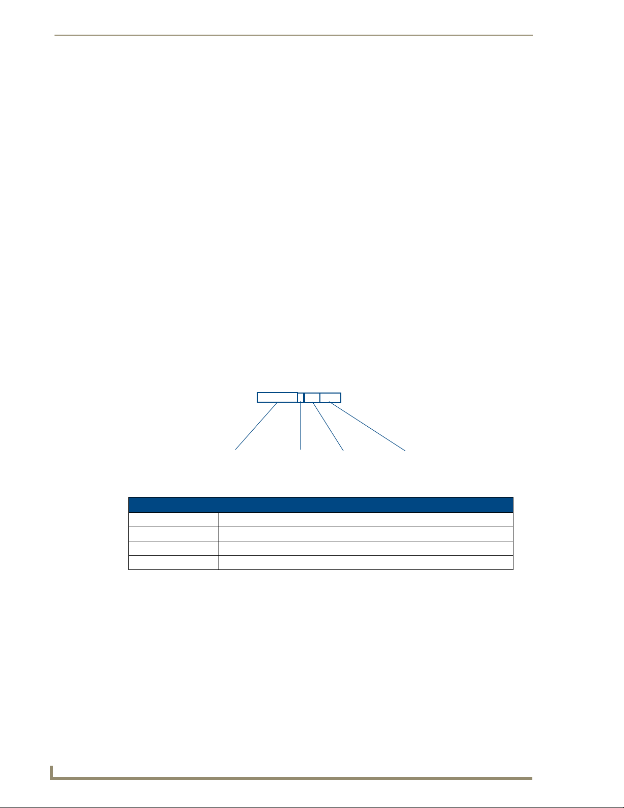
Model Number Vendor ID Date Code
(WW/Y)
FIG. 3 Date Of Manufacture Sticker (on bottom panel)
UDM-0102/RX02 Date of Manufacture Sticker
Model Number Model number and designation, comprised of up to seven characters.
Vendor ID One- or two-character ID code.
Date Code Three-digit date code, comprised of week of year (1-52) and last digit of year.
Consecutive number Starting at “0001” and continuing to “9999”.
Consecutive Number
(4 digits)
2
UDM-1604 Endeleo Multi-Format Distribution Hub
Page 11

Important Safety Markings
Environmental Conditions
The criteria on this page must be observed for the installation of the UDM-0102 and
UDM-RX02.
Temperature
DO NOT install or operate the UDM-0102 or UDM-RX02 in an area where the ambient temperature
exceeds 35ºC (95ºF) or falls below 5ºC (35ºF).
Humidity
DO NOT install or operate the UDM-0102 or UDM-RX02 in an area in which the ambient relative
humidity exceeds 85% or an area that is prone to condensation.
Water / Liquids
DO NOT install or operate the UDM-0102 or UDM-RX02 near water or in a location which may be
prone to water seepage, dripping or splashing.
DO NOT place objects containing liquids on the appliance.
The hub is not waterproof.
External use
DO NOT operate the UDM-0102 or UDM-RX02 outdoors.
UDM-1604 Endeleo Multi-Format Distribution Hub
3
Page 12

Important Safety Markings
4
UDM-1604 Endeleo Multi-Format Distribution Hub
Page 13

UDM-1604 Multi-Format Distribution Hub
UDM-1604 Multi-Format Distribution Hub
Overview
The UDM-1604 Endeleo Multi-format Distribution Hub (FG-UDM-1604) delivers any video source,
including Component, RGB, VGA and S-Video to a virtually unlimited number of display devices
(FIG. 1).
FIG. 1 UDM-1604
The UDM-1604 supports four high-resolution input ports and 16 UDM output ports.
The UDM-1604 delivers media over easily-installed, dedicated Cat5/5e/6, which de-couples distribution
of the media from the corporate backbone. Users can quickly switch and transmit any video source to the
display device, power on/off display devices, and permission user control to select and play video
sources and media servers on demand.
The UDM-1604 offers four high-resolution input ports on the back of each unit. Additional Composite
video inputs (RJ-45 located on the front) enable the connection of four interconnects from a TVM-1600
Managed TV Distribution Hub or four Composite video sources using approved Video over UTP
extenders.
In total, the UDM-1604 system can distribute any combination of the following: four RGBHV sources,
four Component video sources, four S-Video sources or 12 Composite video sources.
Source inputs to the UDM are industry standard VGA, Composite, Component or S-Video feed, and
output is presented as an RJ45 port for connection to Cat5, 5e or 6 twisted-pair Ethernet cable.
Video inputs are connected via the HD15 Input connector on the rear of the UDM. Adapters are used to
bring the different types of video source into the UDM. See the Audio & Video Formats/Resolutions/
Distance section on page 12 for tested and confirmed distances.
Each UDM has an Ethernet network port to provide connectivity to a central management system, or can
be controlled by the onboard configuration pages. A Serial connection is also provided for CLI
administration and diagnostic purposes.
Features
4 multi-format inputs (plus 4 CVBS inputs) x 16 outputs
Digital audio support
Central device control
Compatible with TVM-1600
1U rack-mounting
Multiple Hubs can be cascaded to support higher number of outputs
UDM-1604 Endeleo Multi-Format Distribution Hub
1
Page 14
UDM-1604 Multi-Format Distribution Hub
Compatibility
The UDM-1604 is compatible for use with the UDM-RX01 (FG-UDM-RX01) receiver.
Product Specifications
UDM-1604 Specifications
Power Requirements: • 90-264V AC, 50/60Hz
Front Panel Components
IR Sensor: Infrared receive port (IRRX) for learning IR remote control functions from IR con-
Outputs: 16 RJ-45 ports for connection to Endeleo TVM hubs (via Cat5, Cat5e or Cat6).
A/V Inputs: 4 RJ-45 ports for connection from Endeleo TVM hubs (via Cat5, Cat5e or Cat6).
Rear Panel Components
Network Port: RJ-12 10 BaseT network port is provides network connectivity.
Serial Port: RJ-12 port allows an administrator to control various functions from a command
IRTX Ports: 2 Infrared Transmit (IRTX) ports allow the UDM hub to control IR devices via IR
Input Connectors (A-D): 4 sets of Input connections for up to 4 A/V inputs with the following connectors:
Cascade IN/OUT Ports: These ports allow UDM Hubs to be cascaded together.
IEC Power Connector: Universal switch-mode power supply.
Network Interface: 10baseT
Serial Interface: 9600, 8, N, 1
Max Video Input: • 4 x RGBHV (or)
Operating Environment: • 35°F - 95°F (5°C - 35°C)
Dimensions (HWD):
Weight:
Certifications: • CE/UL/FCC part 15 Class A
• Max power consumption: 130W
trolled devices.
line prompt.
emitters attached to the UDM. The IR cable is attached to the IR panel of the controlled device to receive IR commands issued through the software or remote
control.
• Video
• Audio Left
• Audio Right
• SPDIF
• Cascade In Port (from another UDM Hub)
• Cascade Out Port (to another UDM Hub)
• As a Class 1 appliance the Hub should be connected to a mains supply with a
protective earthing connection.
• The Power On/Off switch is located beside the IEC power connector.
Note: The rating label found to the bottom left of the hub, beneath the IEC connector, contains important information applicable to the Hub’s installation environment.
• 4 x S-Video (or)
• 12 x CVBS (plus)
• 4 x Endeleo TVM-1600 or CVBS
• Max. relative humidity - 85% (non-condensing)
1 3/4" x 19" x 12 1/2" (45 mm x 440 mm x 320 mm)
8.8 lb. (4 Kg)
2
UDM-1604 Endeleo Multi-Format Distribution Hub
Page 15

UDM-1604 Multi-Format Distribution Hub
UDM-1604 Specifications
Included Accessories: • IEC power cord
• 19" mounting brackets
• RS-232 DB-9/RJ-12 connection cable
Note: No A/V interface cables supplied
Other AMX Equipment: • HD15 to S-Video Cable (FG-UDM-SVID01)
• HD15 to 3x RCA Breakout Cable (FG-HD15RCA3F)
• RS232 DB9/RJ12 Connection Cable (FG-RS01)
• UDM-RX01 Multi-Format Receiver (FG-UDM-RX01)
• UDM-RC10 IR Engineering Remote Control (FG-UDM-RC10)
• IR01 IR Emitter Module (FG-IR01)
• IR03 External IR Receiver Module (FG-IR03)
UDM-1604 Endeleo Multi-Format Distribution Hub
3
Page 16

UDM-1604 Multi-Format Distribution Hub
4
UDM-1604 Endeleo Multi-Format Distribution Hub
Page 17

Installation
Overview
The UDM-1604 occupies a single rack space in a standard 19" equipment rack. Rack mounting brackets
and screws are located in the accessories box supplied with the UDM-1604.
Exercise extreme care when lifting or moving the hub within the rack to avoid injury. It
is recommended that you seek the assistance of another person when rack mounting
the UDM-1604.
Rack mounting brackets and screws are located in the accessories box supplied with the UDM-1604.
1. Attach the rack mounting brackets to each side of the UDM-1604 using four M4 screws for each
bracket (FIG. 2).
Installation
FIG. 2 Attach the mounting brackets to each side of the Hub
To prevent injury the Hub must be securely attached to the rack in accordance with
the installation instructions.
ALWAYS use the special rack mount brackets supplied and high quality fixing screws
to ensure the hub is installed in the rack correctly.
2. Place the UDM-1604 in the Rack and hold steady.
3. Two fixing holes are supplied on each side of the UDM-1604. Screw the hub into the rack using the
fixing holes (FIG. 3).
FIG. 3 Screw the hub into the rack using the fixing holes
DO NOT stand other units directly on top of the hub when it is rack mounted, as this
will place excessive strain on the mounting brackets.
Ventilation
ALWAYS ensure that the rack enclosure is adequately ventilated.
Sufficient airflow must be achieved (by convection or forced-air cooling) to satisfy the ventilation
requirements of all the items of equipment installed within the rack.
UDM-1604 Endeleo Multi-Format Distribution Hub
5
Page 18

Installation
6
UDM-1604 Endeleo Multi-Format Distribution Hub
Page 19
Wiring and Connections
UDM-1604 Front Panel Components
The components on the front panel of the UDM-1604 are described below (FIG. 4).
FIG. 4 UDM-1604 - Front Panel Components
IR Learning Sensor
An IR receive port is found at the front of the UDM Hub to the right hand side. This is used to learn
device IR remote control functions from devices such as DVD players, VCRs etc. Common functions
learned include Power on, Power off, Play, Pause, Stop, etc.
Refer to the Protocols and IR Learning section on page 31 for details.
Wiring and Connections
OUTPUT Ports (RJ-45)
The 16 RJ-45 ports on the front panel of the UDM (labelled “OUTPUTS”) provide connectivity to
UDM-RX01 or UDM-RX02 Multi-Format Receivers. This is a standard RJ-45 connector, and UDM
Receivers can be connected via either Cat5, Cat5e or Cat6 cabling (FIG. 5).
FIG. 5 RJ-45 Pinouts
UDM Port Pinouts
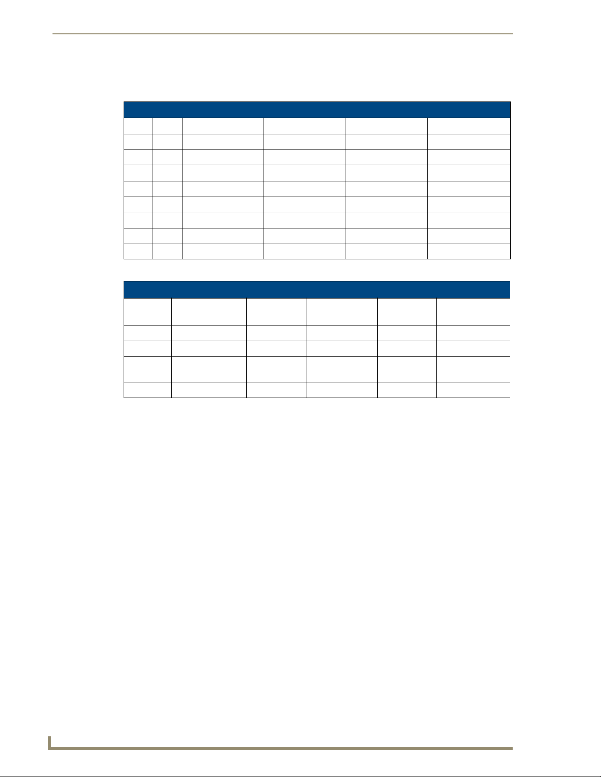
The following table describes the pinout configuration of the UDM port:
UDM Port Pinouts
Pair Color RJ45 Pin Polarity Endeleo Function
White / Blue 5 -
1
Blue 4 +
White / Orange 1 +
2
Orange 2 -
White / Green 3 +
3
Green 6 -
Green
Red
Blue
White / Brown 7 +
4
Brown 8 -, Gnd
UDM-1604 Endeleo Multi-Format Distribution Hub
Bi-Directional Control, Digital Audio, Phantom Power
7
Page 20
Wiring and Connections
UDM Port Transmission Details
The following table provides transmission details for the UDM port:
Transmission on UDM Port
Pair Pin UDM (CVBS) UDM (SVideo) UDM (YPbPr) UDM (RGB)
1 1 CVBS + Luma + Y+ Red +
1 2 CVBS - Luma - Y- Red -
2 3 Chroma + Pr+ Blue+
3 4 Pb+ Green +
3 5 Pb- Green -
2 6 Chroma - Pr- Blue -
4 7 Power, Data, Audio Power, Data, Audio Power, Data, Audio Power, Data, Audio
4 8 Power, Data, Audio Power, Data, Audio Power, Data, Audio Power, Data, Audio
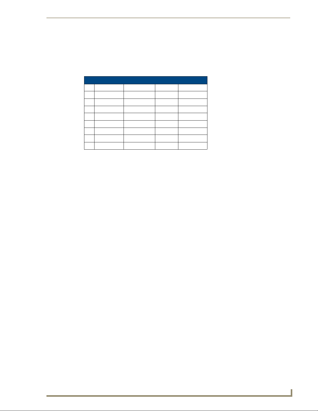
An incorrectly terminated cable will result in the following scenarios:
Incorrectly terminated cable results
Pair Composite
Video
1 No Video 1 No Luma No Y No RED LIT
2 No Video 3 No Chroma No Pr No BLUE LIT
3 No Video 2 NONE No Pb NONE No GREEN
4
SVideo Component
Video
NONE
RGBHV
Video
UDM-1604 Rear Panel Components
FIG. 6 shows the components on the rear panel of the UDM-1604:
FIG. 6
UDM-1604 - rear panel components
User Port
LINK LED
LIT NONE
8
UDM-1604 Endeleo Multi-Format Distribution Hub
Page 21
Wiring and Connections
Network Port (RJ45)
The RJ45 Network port on the rear panel of the UDM-1604 provides 10 BaseT network connectivity.
Pinout Configuration
The following table lists the pinouts, signals, and pairing for the Network port.
RJ45 Network Port Pinouts and Signals
Pin Signals Connections Pairing Color
1 TX + 1 --------- 1 1 --------- 2 Orange-White
2 TX - 2 --------- 2 Orange
3 RX + 3 --------- 3 3 --------- 6 Green-White
4 no connection 4 --------- 4 Blue
5 no connection 5 --------- 5 Blue-White
6 RX - 6 --------- 6 Green
7 no connection 7 --------- 7 Brown-White
8 no connection 8 --------- 8 Brown
FIG. 7 diagrams the pinouts and signals for the Network RJ45 connector and cable.
RJ45 wiring diagram
FIG. 7
Consult the Network Administrator for correct cabling from the UDM-1604 onto the
network. For remote connectivity, the Firewall may have to be configured to open port
2008 for remote connectivity over UDP
Default IP Address
The default IP address of the UDM-1604 is 192.168.0.96.
Once the UDM-1604 is switched on, use the Setup option in the UDM WebConsole to configure the
Hub’s correct IP address (see the Setup Page section on page 38).
The IP address may also be configured via the serial port (refer to the Backend Commands section on
page 62).
UDM-1604 Endeleo Multi-Format Distribution Hub
9
Page 22
Wiring and Connections
Serial Port
The Serial port on the rear panel (labelled “10101”) is available for diagnostic and troubleshooting
purposes.
Connecting the Serial port on the UDM-0102 is not an essential step in the
installation process.
The Serial port on the UDM-1604is an RJ12 connector, and requires a DB9-to-RJ12 adapter cable
(FG-RS01) to connect to a PC for Terminal control.
Serial Port - Default Communication Settings
Use hyper terminal with default serial settings to communicate with the UDM-1604 (and UDM-RX01):
Default Serial Settings
Baud Rate: 9600
Data Bits: 8
Parity: None
Stop B its: 1
Flow Control: None
DB9-to-RJ12 Adapter Cable Pinouts
The following table provides the pinout configuration for the DB9-to-RJ12 adapter cable:
DB9-to-RJ12 Adapter Cable Pinouts
DB9 connector Function Abbreviation RJ12 connector
Pin 1 Not used NC
Pin 2 Transmit Data TD or TX or TXD Pin 1
Pin 3 Receive Data RD or RX or RXD Pin 2
Pin 4 Data Set Ready DSR Pin 3
Pin 5 Signal Ground GND Pin 4
Pin 6 Data Terminal Ready DTR Pin 5
Pin 7 Not Used NC Pin 6
Pin 8 Not Used NC
Pin 9 Not Used NC
10
UDM-1604 Endeleo Multi-Format Distribution Hub
Page 23
Wiring and Connections
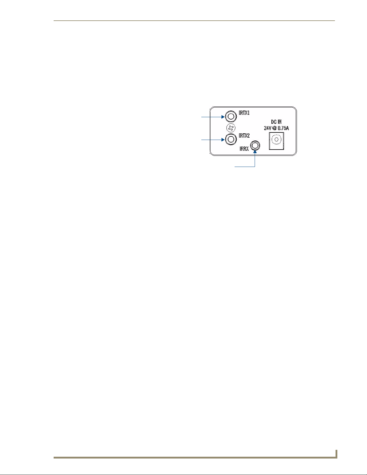
IRTX (IR Transmit) Ports
Two 3.5mm stereo IRTX connections issue IR commands from the UDM hub to the controlled device(s):
TX1 – Transmits IR commands to Device 1
TX2 – Transmits IR commands to Device 2
A maximum of two IR devices (such as DVD players or VCRs) can be connected to the UDM via the
IRTX ports on the rear panel (FIG. 8), and controlled via the WebConsole or remote control.
IRTX1 IR Transmitter port (3.5mm stereo output)
IRTX2 IR Transmitter port (3.5mm stereo output)
IRRX IR Receiver port (3.5mm stereo input)
FIG. 8 IR Transmit/Receive Ports
IR devices controlled via the IRTX ports are typically installed within the same
equipment rack as the UDM.
Connecting an IR Device to an IRTX Port
To issue IR commands to the display device such as power on or power off, an IR01 Endeleo IR Emitter
Module (FG-IR01) is needed:
FIG. 9 IR01 Endeleo IR Emitter Module
Ensure the position of the device corresponds to the position assigned in the Devices
option of the UDM-0102’s WebConsole.
1. Connect the IR Emitter Module cable to the appropriate IRTX port on the UDM-0102.
2. Run the other end of the cable to the display device, and attach the IR Emitter over the device’s IR
sensor by removing the cover on the reverse side of the IR Emitter.
3. The UDM-0102 is now capable of issuing IR commands to the display device.
IR commands for each device on the system have to be learned by the UDM-0102 in order to function
properly. Refer to the Protocols and IR Learning section on page 49 on how to learn a device’s IR
commands.
UDM-1604 Endeleo Multi-Format Distribution Hub
11
Page 24
Wiring and Connections
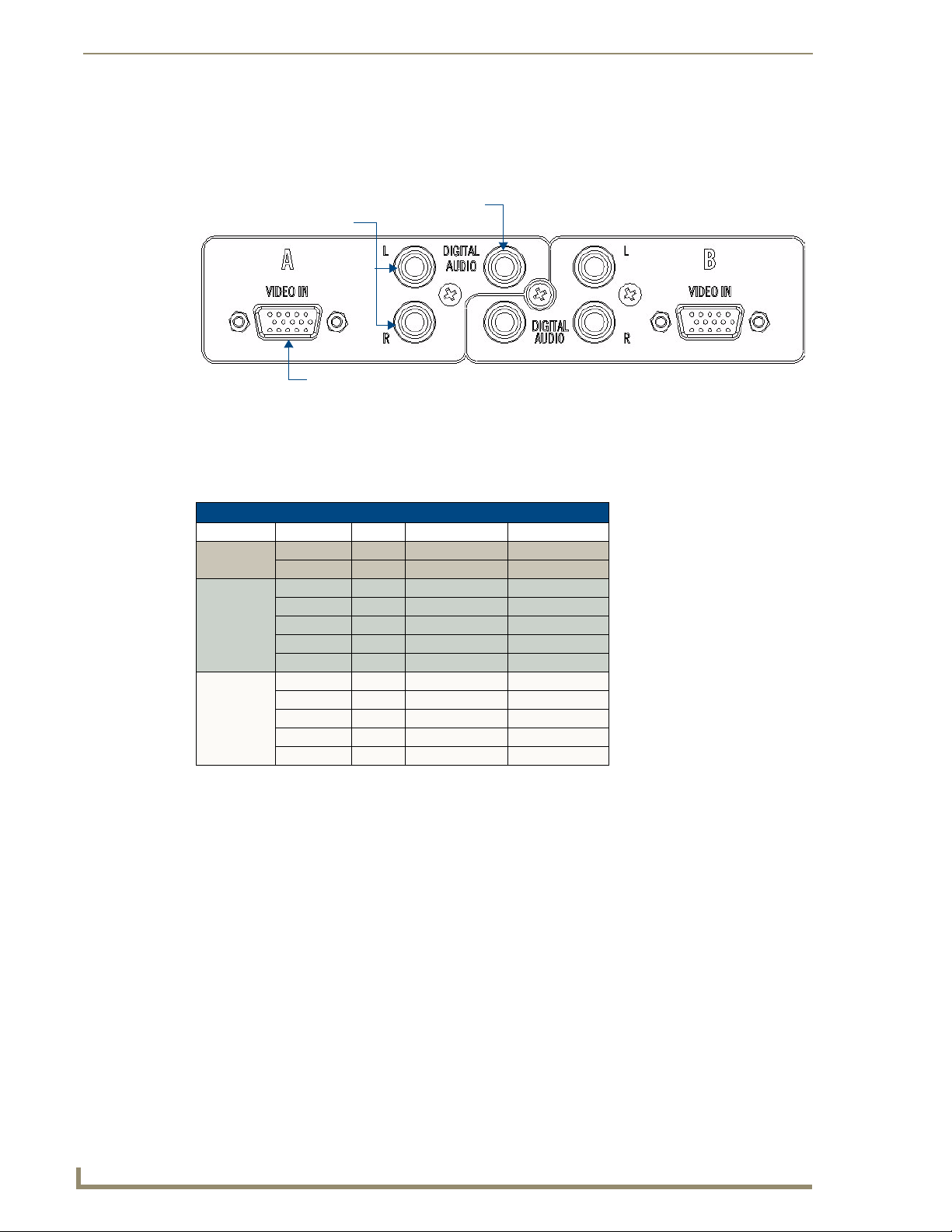
A/V Source Input Connectors
There are four sets of input connectors to the rear panel of the UDM-1604, labelled A, B, C and D
(FIG. 10).
FIG. 10 A/V Source Input connectors (A and B shown)
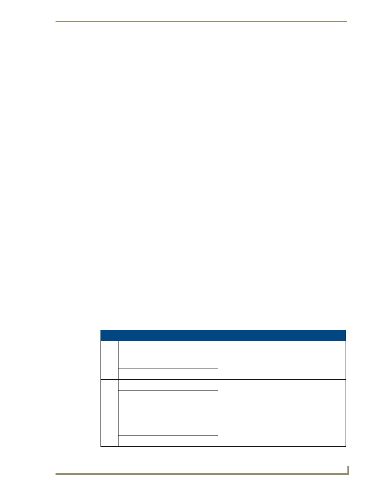
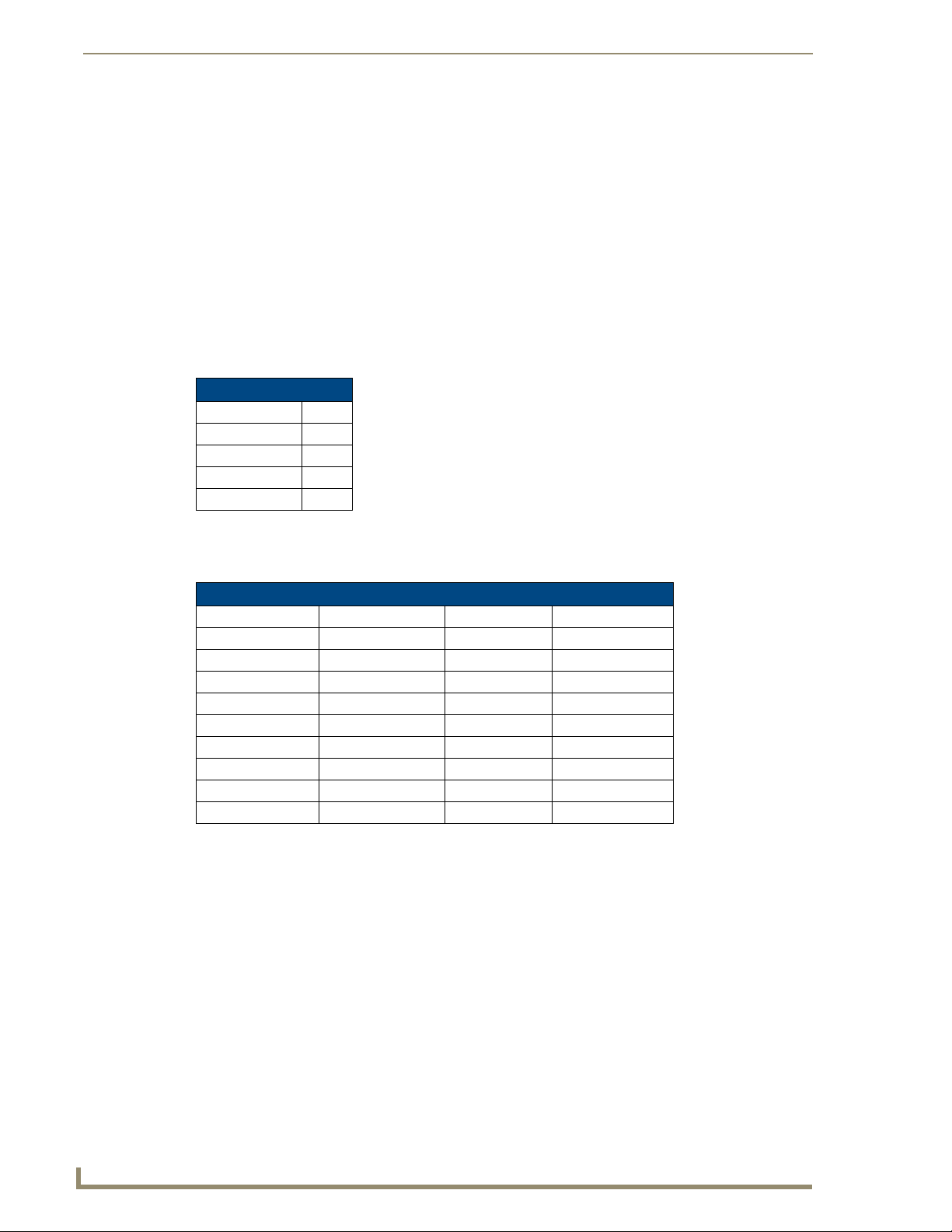
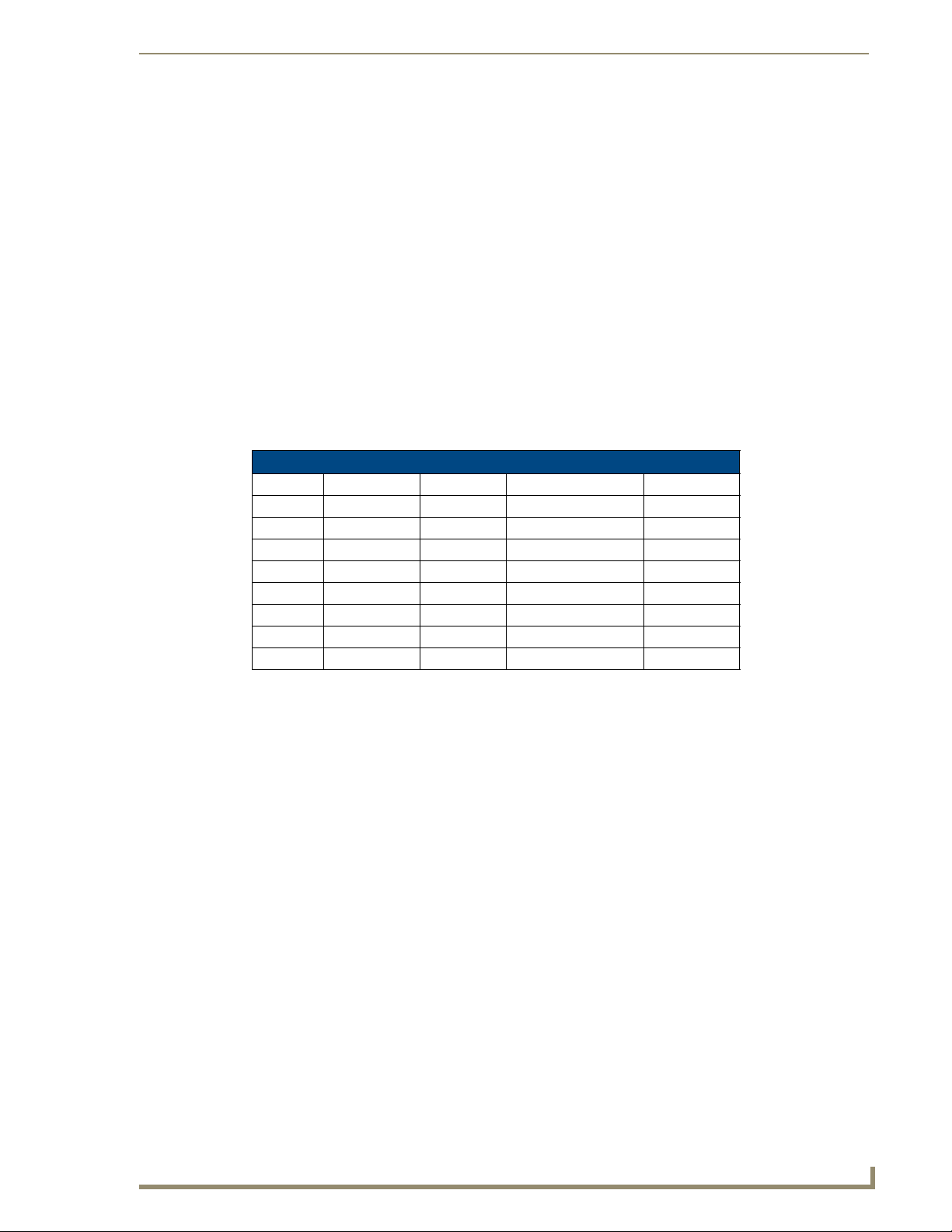
Audio & Video Formats/Resolutions/Distance
The following table provides recommended maximum distances for cable runs, based on video class
type at various resolutions:
Audio & Video Formats/Resolutions/Distance
Class Format Name Distance (m) Distance (ft.)
Composite 720x480 NTSC 300 1000
Component 720x480 480p 300 1000
VGA 640x480 VGA 200 650
Digital Audio Input (SPDIF)
RCA Audio Inputs (L/R)
Video Input (female HD15)
720x756 PAL 300 1000
720x756 576p 300 1000
1280x720 720p 200 650
1920x1080 1080i 150 500
1920x1080 1080p 120 400
800x600 SVGA 200 650
1024x768 XGA 200 650
1280x1024 SXGA 150 500
1600x1200 UXGA 120 400
12
It is important to note that the maximum distances indicated above are not absolute, but are
recommended distances that have been tested to deliver video at the specified resolutions, without
significant signal degradation. In particular, lower resolutions (640 x 480, 720 x 480 and 800 x 600) can
often be delivered significantly further than what is indicated in the table.
Several factors affect the overall quality of the displayed video, including the quality of the twisted pair
cable and connectors used, the nature of the video image itself, as well as the particulars of the
installation and how the video is displayed and viewed.
Two major factors affect the quality of signal transmission include:
Cable Distance: Naturally, long distances cable runs (in excess of 300 meters/1000 feet) are
always subject to resistance and capacitance losses which can negatively impact the quality of
the image.
Skew: "Skew" represents the slight delay that results from the variation in wiring lengths for
each of the twisted pairs. The effects of skew on A/V signals increases with cable length.
Excessive skew can adversely affect video image quality, especially at long cable lengths and
high signal resolutions.
UDM-1604 Endeleo Multi-Format Distribution Hub
Page 25
Wiring and Connections
UDM Hubs allow you to compensate brightness, sharpness and skew delay via options in the Status page
of the UDM’s built-in WebConsole (see the Video Compensation section on page 21).
VIDEO IN Connectors (HD15)
FIG. 11 provides the pin layout for the VIDEO IN HD15 Connectors:
12345
67891
1112131415
FIG. 11 VIDEO IN HD15 Connector
The table below describes the pinout configuration on the VIDEO IN HD15 connector for VGA,
Component, S-Video and Composite connections:
VIDEO IN HD15 Pinout Configuration
Input Pin VGA Component S-Video Composite
1 Red Y Luminance CVBS1
6 Red - Ground Y - Ground Luminance - Ground CVBS1 Ground
2 Green Pb - CVBS2
7 Green - Ground Pb - Ground - CVBS2 Ground
3 Blue Pr Chrominance CVBS3
8 Blue - Ground Pr - Ground Chrominance - Ground CVBS3 Ground
13 Horizontal Sync - - -
14 Vertical Sync - - -
The UDM-HD15RCA3F Endeleo HD15 to 3x RCA Breakout Cable
(FG-HD15RCA3F) referenced in the table above is different from a standard RCA
cable, and an RCA cable cannot be used in its place (the Y, Pb, and Pr connections
are shifted from the VESA standard). If a standard cable is to be used, you will have
to swap the connectors. Contact AMX Technical Support for details.
Connecting a VGA Video Input
Connect one end of a VGA cable to the source device’s VGA output port.
1.
2. Attach the other end of the cable to the appropriate VIDEO IN connection (A or B) on the UDM.
For example, connect to the Video In connection on Input A of the Hub.
3. Connect any audio to the analog (RCA) audio connectors or digital (SPDIF) connector.
Ensure Input A is configured as a “VGA Input” and named appropriately within the
“Inputs” section of the UDM’s built-in WebConsole. Also ensure the correct Audio
Type (Analog L/R or S/PDIF) is selected for the relevant input. Refer to the
Configuration section on page 21 for details.
UDM-1604 Endeleo Multi-Format Distribution Hub
13
Page 26

Wiring and Connections
Connecting a Composite Video Input
1.
2. Attach the other end of the cable to the appropriate VIDEO IN connection (A or B) on the UDM.
3. Connect any audio to the analog (RCA) audio connectors or digital (SPDIF) connector.
Connecting a Component Video Input
1.
2. Attach the other end of the cable to the appropriate VIDEO IN connection (A or B) on the UDM.
3. Connect any audio to the analog (RCA) audio connectors or digital (SPDIF) connector.
Connecting an S-Video Input
1.
2. Attach the other end of the cable to the appropriate VIDEO IN connection (A or B) on the UDM.
3. Connect any audio to the analog (RCA) audio connectors or digital (SPDIF) connector.
Connect the UDM-HD15RCA3F Breakout Cable (FG-HD15RCA3F, not included) to the source
device’s Composite output ports:
A1 = red RCA
A2 = green RCA
A3 = blue RCA
Connect the UDM-HD15RCA3F Breakout Cable (FG-HD15RCA3F, not included) to the video
source device’s Component video output connectors (Red, Green and Blue).
Connect the UDM-SVID01 HD15 to SVideo cable (FG-UDM-SVID01, not included) to the video
source’s S-Video connection.
Cascade IN/OUT Ports
The Cascade IN and Cascade Out ports allow UDM Hubs to be chained together to increase the number
of inputs which can be delivered to the end points (FIG. 12). This is known as "cascading" the hubs.
FIG. 12 Cascade IN/OUT Ports
The Cascade In and Cascade Out ports are used to cascade two UDM hubs.
A UDM-EXP-01 cascade cable (optional) is required to connect the UDM hubs together.
Refer to the Cascading Hubs section on page 49 for details on configuring cascaded Hubs.
14
UDM-1604 Endeleo Multi-Format Distribution Hub
Page 27

Wiring and Connections
IEC Power Connector
The UDM-1604 uses a universal switch-mode power supply, which operates from 90-264V AC,
50/60Hz, with a power consumption of 130W fully loaded.
The rating label found to the bottom left of the hub, beneath the IEC connector, contains
important information applicable to the Hub's installation environment.
The Power On/Off switch is located beside the IEC power connector.
As a Class 1 appliance the UDM-1604 should be connected to a mains supply with a
protective earthing connection.
Powering the UDM-1604 Hub On
1.
Ensure a standard PC mains lead has been connected to the 3-pin power connection, and then
connected to a mains power source.
2. Flip the power switch down to its On (|) position.
Powering the UDM-1604 Hub Off
Where a mains plug (or appliance coupler) is used in the event of a fault, the hub can
be disconnected from the mains by removing the lead from the IEC inlet or from the
mains socket.
It is important that the hub is installed in such a way that this method remains readily
operable.
The user should have easy access to either the IEC inlet or the mains socket in the
event of a fault.
To turn the UDM-1604 off, flip the Power switch to it’s Off (0) position.
UDM-1604 Endeleo Multi-Format Distribution Hub
15
Page 28

Wiring and Connections
16
UDM-1604 Endeleo Multi-Format Distribution Hub
Page 29

Hub Configuration
Connecting to the Multi Format Video Hub
1. The default IP address of the UDM-1604 Hub is 192.168.0.96.
2. Enter the IP address into the address field within a browser window (FIG. 13).
FIG. 13 Default IP address of the Multi Format Video Hub
Hub Login
1. Upon connection to the hub authentication (username and password) is required (FIG. 14).
Hub Configuration
FIG. 14 Endeleo Login screen
2. The username should be left blank.
3. The password is admin.
The password is case sensitive.
4. On initial connection the hub Status page is displayed.
UDM-1604 Endeleo Multi-Format Distribution Hub
17
Page 30

Hub Configuration
Configuring the Hub
Each Hub can be configured for the correct network environment. It is also possible to configure each
Hub for the correct date and time.
Network configuration
Hubs can be configured for the network environment using the Setup page.
1. Click on the Setup option to the left of the screen.
2. The following Hub options should be configured from this page (FIG. 15):
FIG. 15 The Setup Page
a. Hub IP Address, Subnet Mask and Default Gateway;
b. UDP Port (default is 2008) and
c. Hub name (maximum of 30 characters).
The UDM1604 does not support DHCP. Please configure a static IP Address.
3. Once the network environment has been configured, click on Update.
All changes are immediate - once the IP address of the hub has been changed
redirect the web browser to the changed address.
Date and Time configuration
The Setup page is also used to set up the hub date and time, which is used for scheduling.
1. To configure the Hub’s Date and Time, ensure the Setup page is displayed.
2. Configure the Hub by typing in the correct values for the Time and Date.
3. Click on Update when all configuration changes have been completed.
Checking the Hub Time
Clicking on the date and time on the screen simply refreshes the clock to the current time. This can be
useful before creating a scheduled event (FIG. 16).
18
FIG. 16 Hub Date and Time
UDM-1604 Endeleo Multi-Format Distribution Hub
Page 31

Hub Configuration
Restoring Hub Configuration and Connections
To ensure the configuration settings for the Hub are retained each time the hub boots it is advisable to
ensure the following options have been enabled.
FIG. 17 Restoring configuration on power up
Failure to select the Restore Configuration and Connection options will mean if the
Hub is reset the Hub configuration and connections will need to be re-configured.
Restoring configuration and connections
To ensure network configuration and port configuration are restored on boot up select the Restore
configuration on power up.
1. Select the Setup option from the options available.
2. Ensure the checkbox beside Restore configuration on power up has been selected (FIG. 17).
Restoring connections on power up
To ensure inputs are transmitted to the outputs (or ports) on boot up select the Restore connections on
power up.
1. Select the Setup option from the options available.
2. Ensure the checkbox beside Restore connections on power up has been selected.
Hub Reset
Where appropriate the Hub can be reset from the Browser interface. Use the Setup option to reset the
Hub.
1. To reset the Hub click on the Setup option from the left side of the screen.
2. Towards the bottom of the Setup screen the Hub Reset button will be visible (FIG. 17).
3. Click the Hub reset button to reset the hub. The Hub’s network connection will be lost temporarily
and video displays will switch off then on again very quickly.
A power down of the Hub should now be performed to complete the reset procedure.
UDM-1604 Endeleo Multi-Format Distribution Hub
19
Page 32

Hub Configuration
20
UDM-1604 Endeleo Multi-Format Distribution Hub
Page 33

Input Configuration
The second stage in configuring a Hub is to set up the video types and audio sources being presented to
each input port and where appropriate renaming these. This is all achieved through the Inputs page.
Configuring Inputs A-D
1. Select the Inputs option from the available options to the left of screen. The main Inputs screen is
displayed (FIG. 18).
Input Configuration
FIG. 18 Input configuration page
2. An input port can be set to accept (a) a local source or (b) the equivalent source from the previous
hub in a cascaded system (Cascade option enabled).
3. Select the appropriate Input Type. For RGB, VGA, Component or SVideo inputs, only one
connection is possible per input port (FIG. 19).
FIG. 19 Input configuration page - Selecting the Input Type
4. Name the Input Type appropriately.
UDM-1604 Endeleo Multi-Format Distribution Hub
21
Page 34

Input Configuration
5. If the Input Type is Composite, then the screen will refresh and enable the administrator to name
each of the 3 available composite sources separately (FIG. 20).
FIG. 20 Possible Composite Video sources
6. Name the Composite Video types appropriately.
Configuring TVM (AV) Inputs
TV Inputs from an Endeleo TVM hub can also be fed into the UDM hub for display at screens
throughout the location.
The power at the relevant TVM port will have to be disabled using the <k> <port no>
command or through the TVM Web Browser before being connected to a UDM Hub.
Refer to the TVM1600 User Guide.
Configuring TVM inputs for a UDM Hub
Ensure the port on the TVM is configured to display the correct channel – refer to the TVM
1.
documentation.
2. Ensure the power on the TVM port which will transmit the TV feed has been switched off using the
[k] [port no] command (or using the Web Browser).
3. Connect a Cat5 cable from the TVM port to the relevant TVM port on the front of the UDM hub
(FIG. 21).
FIG. 21 TVM (AV) inputs
4. Click on the Inputs option and in the Inputs section configure the TVM input - Name the port
accordingly (FIG. 22).
22
UDM-1604 Endeleo Multi-Format Distribution Hub
Page 35

Input Configuration
FIG. 22 Configuring TVM inputs for a UDM-1604
5. Configure the default channels for each TVM input. For example if you enter "12" in the text field
for TVM-AV1, then every time a UDM user selected TVM-AV1 then they would be initially
switched through to TV channel 12. The channel name is manually entered and helps the user
recognize this from the input selection drop down box on the status page.
If through the user selection page you have enabled pass through (i.e. the ability for
the user to send commands through to the TVM hub to change the channel), then
you may find that the text no longer reflects channel being viewed. If this feature is to
be used, try using a generic channel name such as "TVM port X".
Configuring Audio Types For Inputs
Audio types (Analog L/R or S/PDIF) can be configured for each Input. To configure audio for individual
Inputs;
1. Click on Inputs.
2. In the audio section of the Inputs option, under the Type column, select the type of audio (Analog L/
R or S/PDIF) for the relevant input (FIG. 23).
FIG. 23 Configuring audio types for inputs
Ensure audio has been connected from the Input to the rear of the hub. Ensure the
connections are sound and fixed correctly.
UDM-1604 Endeleo Multi-Format Distribution Hub
23
Page 36

Input Configuration
Cascaded Inputs
UDM Hubs can transmit inputs from other UDM Hubs if cascaded together.
1. To display an input from a cascaded Multi Format Video Hub, click on the checkbox beneath the
Cascade column beside the relevant input.
2. For example if an Administrator selects Cascade beside Input A in this Hub, then Input A from the
Hub(s) interconnected (cascaded) above will be displayed through Input A of this Hub.
The Endeleo cascade cable (UDM-EXP-01) will be connected to the relevant UDM
hubs to permit input cascading. Refer to the Advanced Administration & Technical
Data section on page 31 to configure a cascaded system.
Cascaded Audio
UDM Hubs can transmit audio (and video) from other UDM Hubs if cascaded together. To cascade
audio;
1. Click on the Inputs option.
2. In the Audio section click on the checkbox beneath the Cascade column beside the relevant audio
for the correct input (A, B, C or D).
Renaming Output Ports
1. For easier management the system allows the Administrator to rename any of the Output ports.
2. Click on the Status option from the left hand side of the screen. The 16 output ports should now be
visible (FIG. 24).
FIG. 24 Output Ports
3. Simply click on the relevant Port Name hyperlink on the Status page.
4. The Port Configuration page will now be displayed (FIG. 25).
24
FIG. 25 Configuration options for Output ports
5. Name the port appropriately.
UDM-1604 Endeleo Multi-Format Distribution Hub
Page 37

Input Configuration
Compensating Video at the output ports
Video Compensation Guidelines
Some guidelines on compensating video are listed below, as well as information on compensating video
on LCD panels.
The guidelines focus on;
Skew Endeleo recommends that the video compensation is first adjusted to eliminate
Brightness Once any skew has been eliminated the video should be adjusted for brightness
Sharpness Finally the sharpness of the video should be adjusted eliminating any over or
LCD screens have a tendency to automatically try and compensate the video,
presenting issues when adjusting for skew. Using a CRT monitor to adjust video
quality is often the best way around this.
any skew, using vertical red / green / blue lines.
using a grey scale or equivalent test card.
under shoot of the video. Horizontal black and white bars are one useful method
of tuning sharpness.
Video Compensation Modes
Two modes of compensation are possible, Basic and Advanced.
Basic Mode
1.
Select the Status option from the main options.
2. Select the relevant output port name hyperlink.
3. In Basic mode the system will automatically set up the brightness and sharpness in relation to the
distance entered in the Cable Distance field. Such values are based on a look up table within the hub
(FIG. 26).
FIG. 26 Basic Video Compensation
4. Fine tuning can be achieved by varying the distance entered.
UDM-1604 Endeleo Multi-Format Distribution Hub
25
Page 38

Input Configuration
Advanced Mode
Select the Status option from the main options.
1.
2. Select the relevant port name hyperlink. Click on Advanced.
3. In Advanced mode each of the parameters can be adjusted separately;
Bright (Brightness) adjusts the brightness of the image.
Sharp (Sharpness) adjusts the sharpness of the image (FIG. 27).
FIG. 27 Advanced Video Compensation
4. To add skew delay into any of the video colors simply click on the appropriate color hyperlink.
5. The skew delay rotates through red then green then blue and back to red again – configure
appropriately. Each radio button is equivalent to 2ns delay (FIG. 28).
FIG. 28 Cable distance and Skew controls
26
UDM-1604 Endeleo Multi-Format Distribution Hub
Page 39
Input Configuration
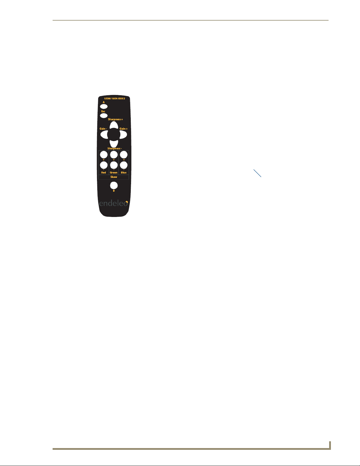
Compensating Video Using the UDM-RC02 Remote Control
Video can also be compensated using the UDM-RC02 Endeleo Multi-Format IR Remote Control
(FG-UDM-RC02).
To compensate video using the UDM-RC02 remote control;
1. Ensure the Endeleo RX Infrared bud is attached to the receiver at the IRRX port (FIG. 29).
Infrared RX port
UDM-RC02
FIG. 29 UDM-RC02 Endeleo Multi-Format IR Remote Control
Infrared RX bud
2. To enter compensation mode push button A then button B on the UDM-RX02 remote control.
3. The amber LED at the Cat5 port on the RX unit will start to flash – indicating the RX is in
compensation mode.
4. Use the buttons on the RX02 remote control to adjust appropriately the following up or down;
Sharpness;
Gain and
Red, Green and Blue.
5. Once the image displayed is of an acceptable quality push the Esc button on the RX02 remote
control to exit compensation mode.
The compensation settings will be specific to this RX unit and stored internally i.e. if
this RX unit is replaced or swapped out the compensation settings will travel with the
RX unit. It may therefore be necessary to re-compensate the RX / replacement RX if
this RX unit is to be used elsewhere or is being replaced.
UDM-1604 Endeleo Multi-Format Distribution Hub
27
Page 40

Input Configuration
28
UDM-1604 Endeleo Multi-Format Distribution Hub
Page 41

Device Configuration and Control
The system allows "centrally located" devices connected to the rear of the UDM Hub e.g. VCR, DVD,
DVR or Satellite Decoders to be managed from the user port. This is performed through the Devices
page.
FIG. 30 UDM-1604 rear panel - IR TX ports
"Centrally Located "means the device is connected directly to the rear of the UDM
hub via the UDM IR ports (Tx1 – Tx4) using an Endeleo IR Tx bud.
The IR Tx bud will then transmit the IR signal from the UDM hub to the device.
An Endeleo IR splitter will be needed for each of the IR ports if using 2 devices per IR port.
If only one device connected to IR TX port 1/2 it will by default be Device 1.
If only one device connected to IR TX port 3/4 it will by default be Device 3.
Device Configuration and Control
Adding Centrally Located Devices
1. Select the Devices option from the options to the left of the screen (FIG. 31).
FIG. 31 Devices screen
2. Name the Device accordingly e.g. DVD Rack2.
Ensure the correct port is selected. Device 1 refers to IR TX1 at the rear of the UDM
Hub, Device 4 refers to IR TX4 at the rear of the UDM hub.
3. Configure the Device with the relevant IR protocol if appropriate.
Refer to the Protocols and IR Learning section on page 31 for details on creating or learning IR
protocols.
4. Configure the Device with the correct Associated Input (i.e. where the Device, as an Input type, is
physically cabled to on the Hub);
If the Device is connected to an input at the rear of the Hub select the relevant associated input
(A-D).
If the Device is connected to a TVM-AV input at the front of the UDM Hub select the relevant
TVM-AV (1-4) associated input.
UDM-1604 Endeleo Multi-Format Distribution Hub
29
Page 42

Device Configuration and Control
Issuing controls to a centrally located IR device
The UDM hub needs to learn the device’s IR protocol i.e. which button on its remote
performs which function. Refer to the Protocols and IR Learning section of this
manual.
1. The control bar at the bottom of the browser screen enables specific controls to be executed via the
browser connection(FIG. 32).
FIG. 32 Command bar for issuing commands to a Device
2. Select the control(s) to be performed for this device. Two controls can be issued to a device 1
nd
(FIG. 33).
2
FIG. 33 Optional controls for a device
The first command is limited to Power On, Off and A/V Select.
st
and
3. Click the tickbox beside the relevant device to select the device to be sent a control. It will highlight
in orange.
4. Click on Send to Included to send the control to the device.
5. Alternatively such controls can be scheduled to occur later. Refer to the Scheduling Events section
on page 43 for details.
30
Custom Controls
Custom Controls permits the Administrator to specify custom IR controls which can sent to the device or
display. A list of custom controls and their IR value can be found in Appendix A of this guide.
To issue a custom control;
1. Select the custom option within the 2
nd
list of commands.
2. Type in the value of the IR code which is to be sent in the relevant box.
3. Execute the custom control or schedule it to occur later.
UDM-1604 Endeleo Multi-Format Distribution Hub
Page 43

Protocols and IR Learning
Overview
Protocols for serial and infrared devices used in the system can be created from the Protocols option.
These protocols will allow the UDM Hub to control serial and infrared devices connected via the Hub.
For serial devices the following information is key to the successful function of the serial device;
Serial cable and pinouts;
Serial settings for correct communication with the device and
Manufacturer’s command strings equivalent to the command to be executed from the UDM
Hub.
For IR devices the device’s Infrared controls (remote control key presses) will have to be learned by the
UDM Hub.
Creating a Serial Protocol
1. Click on the Protocols option.
2. If a serial protocol is required click on the downward arrow beside the Serial Protocol field. Click
on New.
3. Name the serial protocol appropriately and assign the protocol a setting (baud rate, parity etc.).
Protocols and IR Learning
FIG. 34 Creating a new serial protocol
When configuring the serial settings OP means Odd, Parity and EP means Even,
Parity.
4. Once the protocol has been named and a setting (baud rate, Parity) configured, click on Initialise –
this will clear the RX of any pre-loaded serial commands.
5. Select an Action to be performed from the Action drop down menu e.g. Power off or Power on
(FIG. 35).
FIG. 35 Creating a serial command for the action
6. Key in the Serial command (serial string) equivalent for this action.
The serial string which reflects the action has to be accurate for the serial command
to work. Consult the Manufacturer’s web site or documentation to ascertain the
correct string for this serial device.
7. Click on Add to create the new protocol.
8. Repeat if necessary for other serial commands which are to be stored under this protocol name.
9. Once completed the protocol can now be assigned to relevant devices.
UDM-1604 Endeleo Multi-Format Distribution Hub
31
Page 44

Protocols and IR Learning
It is presumed that the serial device connected to the Endeleo RX has the
appropriate serial settings as described and the correct serial cable/pinouts
configured in order to function correctly with the Endeleo RX unit.
Updating the UDM Receiver With the Serial Protocol
A UDM-RX01/02 Receiver, which will issue the relevant serial commands to the
device, must be connected to the relevant port via a Cat5/e/6 cable. Remember the
serial commands are stored within the Receiver.
1. Ensure the Serial Protocol and commands have been created previously.
2. Click on the Status page.
3. Click on the port number hyperlink which the serial device is attached to. (It is the Endeleo RX
4. Once the port properties become visible click on the arrow to the right of the Protocol field.
5. Select the Serial protocol which this RX unit will download. This may take a few minutes
6. A message will appear saying “Loading Protocol – Please wait” once this has disappeared the
unit which will issue the serial command over the serial cable connected between the RX unit and
the device).
depending on how many commands are within the protocol.
Serial protocol has been downloaded to the RX device. Commands can now be sent from the Hub
Web pages to the serial device.
A new table for this device’s Serial control is what is actually being created. When the
administrator decides to create further commands particular to this serial device they
will be stored within this table e.g power off, power on. If new commands are to be
created in future ensure the correct Serial Protocol has been selected before defining
new commands to ensure commands are stored in the correct table. There is one
protocol/table per UDM Receiver.
Creating and Learning an IR Protocol
Infrared (IR) protocols can be learned by the UDM Hub by using the device’s remote control to
programme its commands into the UDM Hub. This is performed by using the Protocols section of the
web pages.
The device’s own remote control can still be used locally at the device to control the
device.
The UDM Hub can learn between 8 and 25 IR commands depending on the actual command length and
protocol used.
IR Learning with a Device’s Remote Control
Click on the Protocols option.
1.
2. Click on the downward arrow beside the IR protocol field. Click on New.
32
UDM-1604 Endeleo Multi-Format Distribution Hub
Page 45

Protocols and IR Learning
A new table for this device’s remote control is what is actually being created. When
the administrator decides to create further commands e.g power off, power on
particular to this remote control they will be stored within this table. If new commands
are to be created in future ensure the correct IR Protocol has been selected before
recording new commands to ensure commands are stored in the correct table. There
is one protocol/table per UDM Receiver.
3. Name the Infrared protocol appropriately and click on Initialise (FIG. 36).
FIG. 36 Creating a new IR protocol (table)
4. The hub prompts for the relevant action which is to be performed (e.g. vol up). Select the relevant
action from the Action drop down menu (e.g. vol up - FIG. 37).
FIG. 37 Creating a new action for an IR protocol
Ensure the device’s remote control is pointing to the IR sensor located at the front of
the UDM Hub when performing key presses. If not the key presses may not be stored
in the UDM Hub.
5. Click on Step 1. A message saying Press key on remote will appear. Click the key on the device’s
remote control which will manage the action vol up (FIG. 38).
FIG. 38 Configuring the device’s remote Step 1
6. Click on Step 2. A message saying Press key on remote will appear. Click the key on the device’s
remote control which will manage the action vol up (FIG. 39).
FIG. 39 Configuring the device’s remote Step 2
The IR learning process requires that the command on the device’s remote is learned
twice i.e the same remote control command needs to be repeated at Step 2.
UDM-1604 Endeleo Multi-Format Distribution Hub
33
Page 46

Protocols and IR Learning
Updating the UDM Receiver With the IR Protocol
A UDM-RX01/02 Receiver, which will issue the relevant IR commands to the device,
must be connected to the relevant port via a Cat5/e/6 cable. Remember the IR
commands are stored within the Receiver.
1. Ensure the Infrared Protocol has been created previously.
2. Click on the Status page.
3. Click on the port number hyperlink which the device is attached to. It is the Endeleo RX unit
4. Once the port properties become visible click on the arrow to the right of the Protocol field.
5. Select the IR protocol which this RX unit will download. This may take a few minutes depending on
6. A message will appear saying “Loading Protocol – Please wait” once this has disappeared the IR
Deleting Protocols
Protocols can be deleted individually by type (Delete) or all protocols can be removed from the UDM
Hub (Delete all) i.e. all serial and all Infrared protocols can be deleted using Delete All.
1. Click on the Protocols option.
2. To delete a protocol click the Delete hyperlink in the serial section to delete a serial protocol or click
which will transmit the IR command to the devices IR interface.
how many commands are within the table.
protocol has been downloaded to the RX device. IR commands can now be sent from the Hub Web
pages to the device.
the Delete hyperlink in the Infrared section to delete an infrared protocol.
The last created or currently highlighted serial or infrared protocol will be deleted
when using the Delete hyperlink.
Deleting All Protocols (Serial and IR)
All protocols can be deleted from the UDM Hub.
1. Click on the Protocols option.
2. To delete all protocols click the Delete all hyperlink in the Serial section i.e. the top half of the
screen. This deletes all Serial and all Infrared protocols.
34
UDM-1604 Endeleo Multi-Format Distribution Hub
Page 47

Operating the UDM Hub
Hub Status
All of the system control is handled using the Status page. From this page it is possible to control:
Which input is displayed on which output;
Send device control messages to the display device and
Create an event for management via the scheduling engine (FIG. 40).
Operating the UDM Hub
FIG. 40 Main Status page
Selecting Inputs For Display
1. Click on the Status option.
2. Each port on the hub has a drop down box, in which will be displayed all of the inputs (configured
in the Inputs option) available to this particular Port (FIG. 41).
FIG. 41 Inputs available for a port
"Inputs" mean inputs directly connected to the rear of the chassis e.g. Inputs A-D,
devices connected to IRTx ports 1 – 4 or TVM (Managed TV) ports connected to the
front of the UDM Hub at the AV Inputs ports.
3. Select the appropriate Input (VGA display, DVD, TV Channel) which this port will display.
UDM-1604 Endeleo Multi-Format Distribution Hub
35
Page 48

Operating the UDM Hub
Selecting Multiple Inputs For Display
An input can be assigned to multiple ports to save administration time.
1. Click on the Status option.
2. To change more than one port to display a particular input, select the input name from the drop
3. Select the check boxes (beneath the Include column) beside the relevant ports which are to display
4. The selected ports will be highlighted in Orange.
The Include All link toggles all the channels to be included on or off.
5. Select the Execute hyperlink button at the top of the screen to configure the ports to display the
down list beside the Included option. This is located towards the top of the status page on the top
toolbar.
the input visible beside Included.
Included input (FIG. 42).
FIG. 42 Execute button
6. If configuration changes are complete then deselect the relevant ports by clicking their relevant
tickbox. The orange highlight will now disappear.
Changing an Input
The input being displayed at a port can be changed at any time. Simply select the new input to be
displayed at this port. To change multiple ports select/include those ports appropriately (FIG. 43).
FIG. 43 Changing an Input
36
UDM-1604 Endeleo Multi-Format Distribution Hub
Page 49

Operating the UDM Hub
User Control
Administrators can issue commands from the UDM Browser Interface. These commands are issued
from;
The toolbar located at the bottom of the web browser to the selected ports;
The user control drop down options from the Status page for the relevant port or
The user control section from within a selected port i.e. once a port’s hyperlink has been
clicked the User Control option will be visible.
Schedules are also used to issue commands at a pre-determined time to inputs and
devices.
Issuing Commands To a Port
Ensure the device’s Infrared commands have been learned by the Hub first. Refer to
the Protocols and IR Learning section.
Control of the input is performed in a similar way to changing the input to be displayed. A Control or
command can either be issued per Input or issued across all or groups of ports.
1. Click on the Status option. Ensure the relevant port is known.
2. Click on the downward arrow to the right of the Control field. Refer to (FIG. 44).
FIG. 44 Selecting a control to be executed at the port(s)
3. A standard list of controls programmed into the web interface will be displayed. Select the required
control (FIG. 45).
FIG. 45 Standard list of Controls
Where a custom control is required type in the IR code for the command. Refer to the
Appendix B – Endeleo IR Codes section on page 65.
4. Once selected click on the Execute button (FIG. 46). The command will be executed for the
relevant port.
FIG. 46 Execute button
UDM-1604 Endeleo Multi-Format Distribution Hub
37
Page 50

Operating the UDM Hub
Ensure a TX Infrared bud (smaller of the IR buds) is connected to the Endeleo RX
unit’s IRTX port. Attach it to the Device’s IR sensor before issuing a command. This
Infrared TX bud is used to transmit the command from the RX unit to the device’s
infrared sensor
Issuing Commands To Multiple Ports
As with the input selection it is also possible to send multiple control commands to all or selected ports.
1. Click on the Status option.
2. Select the check boxes for the outputs to be changed (the Include All link simply toggles all the
Because the control strings are stored in the receiver units, a global command across
multiple ports will allow any range of display devices to be controlled simultaneously.
3. Click on the downward arrow to the right of a Control field in one of the selected ports. Select the
4. Select the Execute button (FIG. 46).
Issuing Commands to Centrally Located Devices
channels to be included on or off). The ports will now be highlighted in orange.
control to be executed.
It is also possible to control centrally located hardware such as DVD players, using the Devices page.
Remember an IR-TX bud coming from the rear of the UDM Hub will sit over the Device’s IR sensor.
1. Click on the Devices option from the main options (FIG. 47).
FIG. 47 Controls available for a device
2. First select the device(s) you wish to control by clicking on its tick box beneath the Include column.
3. From the dark grey toolbar at the bottom of the screen select the control(s) that you wish to send.
2 commands (1st and 2nd, if necessary) can be sent.
4. Now click the Send to included hyperlink to issue the control(s).
The Device’s commands must have been learned by the UDM hub in order to
function. Refer to the Protocols and IR Learning section on page 31.
38
UDM-1604 Endeleo Multi-Format Distribution Hub
Page 51

Operating the UDM Hub
Assigning a Command to an Endeleo UDM-RC02 Remote Control
Ensure the Infrared command which the UDM-RC02 Remote control will issue has
been learned by the Hub first. Refer to the Protocols and IR learning section of this
manual.
Click on the Status page. Click the appropriate Port name hyperlink.
1.
2. Click on User Control at the top right of the screen (FIG. 48).
FIG. 48 User Control option
From the main status screen click on User Control at the correct port to access the
User Control screen also.
3. Look at the keys (0 to F, which represent the keys on the UDM-RC02 Remote Control) to the left of
screen.
4. In line with the Key (e.g. key F) move the mouse across to the Control field and select the command
from the drop down list which this key (key F) on the UDM-RC02 Remote Control will issue. For
Example choose Play (FIG. 49).
FIG. 49 Assigning Play to key F on the Endeleo remote control
Ensure the correct key on the Endeleo Remote RX01 corresponds with the correct
command.
5. Now select whether this button (on the remote control) should be associated with the Port (display
device) or an actual Device (e.g. a DVD player added to the system as a device) when it is pushed.
6. The Endeleo RX unit will now accept the relevant command from the UDM-RC02 Remote Control
i.e. key F on the UDM-RC02 Remote Control will play the device (DVD).
UDM-1604 Endeleo Multi-Format Distribution Hub
39
Page 52

Operating the UDM Hub
Passthrough Mode (Inputs A – D)
Devices can also be placed into Passthrough Mode. Passthrough Mode allows an Endeleo TVM remote
control (or Sky remote control) to be used to control TV channels being viewed through the UDM Hub
or devices connected to the UDM Hub e.g. a DVD player.
A device e.g. a DVD player can be stopped, paused and started etc. using the TVM
remote control or a Sky plus remote control.
The following steps must be taken if Passthrough Mode is to function correctly;
Configuring a Device for Passthrough Mode
The device needs to be added to the system as both an input and as a device.
1. Cable the device as an input coming into the rear of the chassis e.g. into Input A as for a normal
2. Add the device as an input in the Inputs option.
3. Learn the device’s protocol using IR Learning – refer to the Protocols section and Advanced
4. Add the device into the Devices option as normal and assign it its IR protocol.
Device must be added to the system as an Input.
IR blaster (correct IR port) at the rear of the chassis must be connected to the device.
Device must be added to the system as a Device and be assigned its learned protocol.
Port must be configured for Passthrough Mode.
input.
Administration section of this manual.
Ensure the relevant IR blaster port is cabled up to the device also e.g. if the device is
connected to Input A cable IR port 1 to the device, if Input B cable IR port 2 to the
device etc.
5. The device has now been added as an Input (and as a device).
Configuring a Port for Passthrough Mode
To configure a port to access a Device in Passthrough Mode;
1. Select the Status option.
2. Once the main Status screen is visible click on User Control for the correct port (FIG. 50).
FIG. 50 Placing a port into Passthrough Mode
3. Select the relevant Remote Control from the Remote Type, which will be used to put the device into
passthrough mode e.g. key 0 on the UDM-RX01 remote control will put the device into passthrough
mode.
4. Click on the Passthrough checkbox to the right of the key dedicated to putting the RX into
Passthrough Mode e.g. key 0 on the remote.
5. The device (Sky box, DVD Player) can now be controlled directly at the RX end.
40
UDM-1604 Endeleo Multi-Format Distribution Hub
Page 53

Operating the UDM Hub
6. To exit Passthrough Mode press the TV key on the Sky remote or a non-passthrough key on the
remote control.
Passthrough Mode (Inputs TVM-AV1 – TVM-AV4)
Similarly a TVM Input (TVM-AV1 – TVM-AV4) can be configured for Passthrough Mode.
Observe the following guidelines;
Ensure the IR Blaster is connected to the correct IR port at the rear of the UDM Hub. For
example IR Port 1 – which will be associated with Device 1 and input TVM-AV1.
The relevant Device Number is selected to reflect the relevant IR Port (same Device number as
IR port on the rear of the UDM Hub).
Ensure the Device number is associated with the relevant TVM-AV port. For example Device
1 is associated with TVM-AV1.
The protocol for the Device (for example a Sky box) has been learned. Refer to Advanced
Administration in this guide.
Relevant key has been assigned in User Control to enter Passthrough Mode for the TVM-AV
input.
The TVM-AV Input has been enabled for Passthrough Mode.
If a TVM Hub is directly connected to port TVM-AV1 on the UDM Hub and an IR
Blaster connected to IR Port 1 (at the rear of the UDM Hub) is associated with Input
A, then only channel changes will be permitted on the TVM Hub – i.e. NON-
Passthrough Mode.
Using Passthrough Mode
Once a device has been configured for Passthrough Mode the relevant remote control is used to control
the device.
Press the previously configured key on the relevant remote control (UDM-RX01 or Sky remote control)
to enter passthrough mode.
If accessing a Sky Box through passthrough, click on the Sky button on the Sky remote
control. Now use the Sky Remote control as normal. (Press TV on the Sky remote to exit
passthrough mode).
If accessing a DVD player through passthrough, click on the relevant button on the DVD
remote control to play, pause, stop eject etc. Use the DVD Remote control as normal.
If accessing an Endeleo TVM Hub through passthrough, click on the Up or Down channel on
the TVM remote control, to toggle between channels.
Exiting Passthrough Mode
To exit passthrough mode, click on any key on the remote control (which accessed passthrough mode)
which is not configured as a control enabled key. If accessing a Sky box press TV on the Sky remote to
exit passthrough mode.
UDM-1604 Endeleo Multi-Format Distribution Hub
41
Page 54

Operating the UDM Hub
Dual Output
"Dual output" permits a single input to be viewed as 2 separate output types. For example a port could be
configured for the Dual Output of VGA and Component video. This means at the RX end the input could
be delivered to two separate display devices over the relevant connections at the RX.
To place a port into Dual Output mode;
1. Click on the Status screen.
2. Click on the relevant port hyperlink.
3. Click on the Dual Output checkbox to permit the port to display the single input as 2 separate types
FIG. 51 Enabling Dual Output
Ensure the correct cabling is in place at the RX to accommodate the 2 separate
signals.
Locking One or More Ports
at the RX (FIG. 51).
Locking a port(s) will prevent any user interaction at that port(s).
1. Click on the Status option.
2. To lock any or all output ports to a specific source thus preventing any user control simply select the
Locked check box beside the relevant port(s) (FIG. 52).
FIG. 52 Locking a port
3. Once selected click on the Execute button at the top of the screen. The port is now locked to that
display.
Multiple ports can be locked by clicking on the Include check box relevant to the port,
then clicking on Execute to lock the ports.
42
UDM-1604 Endeleo Multi-Format Distribution Hub
Page 55

Scheduling Events
Scheduling Events for Inputs and Devices
The hub has an on board clock enabling scheduled events to be created at a predetermined time in the
future. Up to 16 events can be scheduled at a time.
Creating a scheduled event requires two actions and uses the global control toolbars at the top (Inputs)
and bottom (Commands) of the pages;
Schedule Link at the top of the page is to schedule Inputs, Devices or TVM to be displayed at
a particular time and
The Schedule Link at the bottom of the page is to schedule commands to be executed at a
particular time.
The event (channel changing, port locking or device control) is selected in the same way as described
previously, as are the ports that this is to be applied to.
If Execute had been selected, the command would be issued immediately. The
Schedule option is used to run the command at a later date.
Scheduling Events
Scheduling an Input
Inputs can be scheduled to appear on certain screens if necessary. For example flight information coming
in on Input A to ports 1 and 2 can be changed to Train information at a specific time.
1. From the top toolbar, select the name of the input which the schedule is to be applied to e.g. Flights
(FIG. 53).
FIG. 53 Selecting an input for a scheduled event
2. Select the ports which the input will be displayed on by clicking on the Include check box at the
relevant ports. The ports are highlighted in orange.
3. Click on the Schedule button at the top of the page. The Schedule page should now be visible
(FIG. 54).
FIG. 54 Main Schedule page
UDM-1604 Endeleo Multi-Format Distribution Hub
43
Page 56
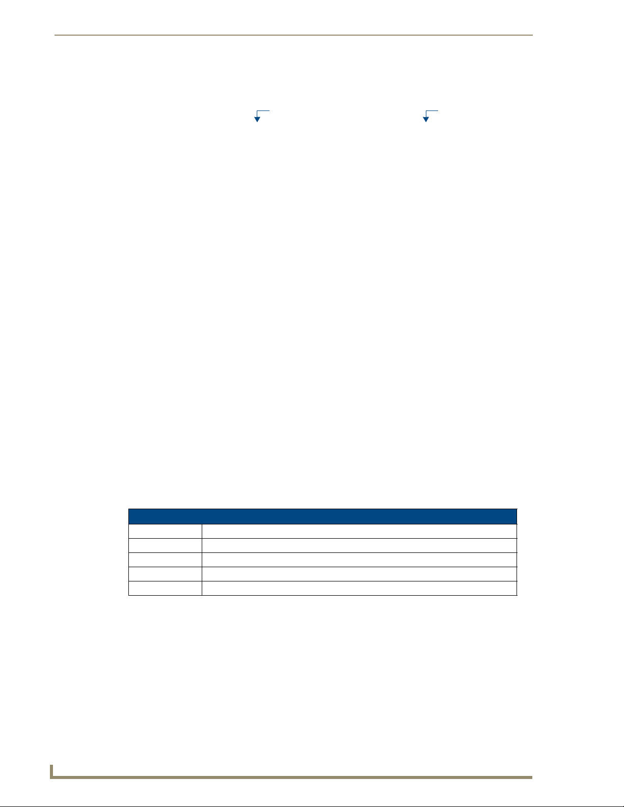
Scheduling Events
4. The Input(s) and port(s) selected from the Status page will automatically appear in the scheduled
event (FIG. 55).
Input
FIG. 55 Input and Ports within schedule
Ports
5. Name the scheduled event in the field provided (FIG. 56).
FIG. 56 Naming the scheduled event
6. Select the frequency (Day, Hour etc.) of the event and the time for the event to occur (FIG. 57).
Refer to Event Times below to configure the correct time.
FIG. 57 Selecting the event frequency and time
Event Times specify when an event will occur (FIG. 58).
FIG. 58 Possible event times
A scheduled event can execute in a number of ways;
Scheduled Events
Hour Event happens at a specified time and then every 60 minutes.
Day Event happens at a specified time and then every 24 hours.
Weekday Event happens at a specified time and then every 24 hours (Monday through Friday).
Sunday Event happens every Sunday at specified time.
Monday-Saturday As with Sunday.
7. Once the frequency of the event has been configured click on Add to add the schedule to the list of
scheduled events.
The event must now be enabled. Click the event’s Enabled tickbox beneath the Enabled
column (FIG. 59). The event will execute at the specified time.
44
UDM-1604 Endeleo Multi-Format Distribution Hub
Page 57

Scheduling Events
Enabled Scheduled Event
FIG. 59 An enabled schedule
Scheduling an Event(s) for Device(s)
Using the Devices page it is also possible to create device control events to happen on a scheduled basis.
As with the Status page the event is created in the normal manner.
1. Select the control or controls (1
bottom of the screen.
FIG. 60 Controls to be executed
2. Select or include the device(s) which the control should be sent to by clicking on its tick box. The
device(s) will be highlighted in orange.
3. Instead of selecting the Send to included hyperlink select the Schedule link (at the bottom of the
page).
4. Select the frequency (Day, Hour etc.) of the event and the time for the event to occur. Refer to
Event Times below (FIG. 61) to configure the correct time.
st
or 2nd) to be executed (FIG. 60) from the grey toolbars at the
FIG. 61 Event Times
Event Times specify when an event will occur (FIG. 62).
FIG. 62 Possible event times
A scheduled event can execute in a number of ways;
Scheduled Event
Hour Event happens at a specified time and then every 60 minutes.
Day Event happens at a specified time and then every 24 hours.
Weekday Event happens at a specified time and then every 24 hours (Monday through Friday).
Sunday Event happens every Sunday at specified time.
Monday-Saturday As with Sunday.
UDM-1604 Endeleo Multi-Format Distribution Hub
45
Page 58

Scheduling Events
5. Once the frequency of the event has been configured click on Add to add the schedule to the list of
scheduled events.
6. The event must now be enabled. Click the event’s Enabled tickbox beneath the Enabled column
(FIG. 63). The event will execute at the specified time.
Enabled Scheduled Event
FIG. 63 An enabled schedule
Configuring the UDM-RC02 Remote Control for Scheduling
Ensure the relevant schedules have been defined before assigning schedules to the
UDM-RC02 Remote Control.
1. Click on the Status page. Click the appropriate Port name hyperlink and click on User Control at
the top right of the screen (FIG. 64). Alternatively, click on User Control from the main Status
screen.
46
FIG. 64 User Control option in Port Details
2. Look at the keys (0 to F, which represent the keys on the UDM-RC02 Remote Control) to the left of
screen.
3. In line with the Key (e.g. key F) move the mouse across to the Schedule field and select the
appropriate schedule from the drop down list (FIG. 65) which this key (key F) on the UDM-RC02
Remote Control will issue. For Example choose Flat Panels on.
FIG. 65 Assigning a schedule to key F on the Endeleo RX01
Ensure the correct key on the UDM-RC02 Remote Control corresponds with the
correct schedule.
UDM-1604 Endeleo Multi-Format Distribution Hub
Page 59

Scheduling Events
4. The Endeleo RX unit will now accept the relevant command from the UDM-RC02 Remote Control
(i.e. key F on the UDM-RC02 will power on the Flat Panels).
Preset Scheduling
From the Schedule page it is possible to create a Preset scheduled i.e. events based on schedules already
created i.e. combining 2 or more existing events to create a Preset event (FIG. 66).
FIG. 66 Main Schedule screen
1. Click on the Schedule page. To create a combination event simply click each schedule’s Preset link
(FIG. 67) - the individual schedule numbers appear in the Preset bar at the bottom of the screen.
FIG. 67 Selecting individual schedules
2. Define a frequency / time for the Preset schedule to happen. This overrides any previously created
frequency / times used in the Preset schedule.
3. Assign the Preset schedule a unique name by replacing the default text (FIG. 68).
FIG. 68 Naming a Preset schedule
4. If an interval is required between each individual schedule within the Preset schedule, specify a time
interval (in minutes) in the interval field.
5. Finally click the Add hyperlink button. The Preset event should now appear in the event list.
6. Enable the event also by clicking on the tick box beneath the Enable column beside the
combination event (FIG. 69).
FIG. 69 Enabling a Preset schedule
UDM-1604 Endeleo Multi-Format Distribution Hub
Enabled Scheduled Event
47
Page 60

Scheduling Events
No tick box appears to the left of the combined event as several combined events can
not be added together.
48
UDM-1604 Endeleo Multi-Format Distribution Hub
Page 61

Cascading Hubs
Overview
UDM Hubs can be connected (cascaded) together to increase the number of inputs which can be
delivered to the end points. This is known as cascading hubs together.
The Cascade In port and Cascade Out ports will be used when cascading 2 Hubs together.
A cascade cable UDM-EXP-01 will be required to connect Hubs together. This cable can be purchased
from AMX, as it is not shipped with the Hub.
Configuring a Master Hub
A Master Hub will have to be configured (to synchronize audio) in any cascaded system. This will
normally be the first Hub in the system and should follow a top (Master) to bottom (Slave) configuration.
In theory there is no limit to the amount of Hubs cascaded i.e. one Master only but multiple Slaves.
To configure a hub as a Master Hub;
1. Click on the Setup option.
2. Click on the Cascade master option (FIG. 70) to configure the Hub as a Master Hub.
Cascading Hubs
FIG. 70 Configuring a Master Hub
Cascading 2 Hubs
1. To cascade 2 hubs together, ensure the hubs are located within distance of the Endeleo UDM-EXP-
01 cascade cable.
2. Attach one end of the UDM-EXP-01 cable to the Cascade Out port on the Hub whose video source
is to be cascaded to another hub.(FIG. 71)
FIG. 71 Hub which will forward (Cascade Out) video source
3. Ensure the connection clips are fixed securely to ensure a good connection on the Cascade Out port.
4. Attach the other end of the UDM-EXP-01 cable to the Cascade In port on the Hub (FIG. 72), which
will transmit this cascaded video source to a display device (Rx) or indeed to another hub if using
more than 2 hubs for cascading.
FIG. 72 Hub which will display (Cascade In) video source
UDM-1604 Endeleo Multi-Format Distribution Hub
49
Page 62

Cascading Hubs
5. Ensure the connection clips are fixed securely to ensure a good connection on the Cascade In port.
(FIG. 73)
FIG. 73 Two Hubs cascaded together
Cascading three Hubs
1.
To cascade 3 hubs together ensure the hubs are located within distance of the Endeleo UDM-EXP01 cascade cables.
2. Attach one end of the UDM-EXP-01 cable to the Cascade Out port on the Hub whose video source
is to be cascaded to another hub.
3. Ensure the connection clips are fixed securely to ensure a good connection on the Cascade Out port.
4. Attach the other end of the UDM-EXP-01 cable to the Cascade In port on the second Hub, which
will transmit this cascaded video source to the third hub.
Ensure the connection clips are fixed securely to ensure a good connection on the
Cascade In port.
5. Finally, connect the Endeleo UDM-EXP-01 cable to the Cascade Out port on the second hub and
connect it to the Cascade In port on the third Hub. (FIG. 74).
FIG. 74 Three Hubs cascaded together
50
UDM-1604 Endeleo Multi-Format Distribution Hub
Page 63

Cascading Hubs
Software Configuration For Cascading Hubs
Once the cabling has been connected, it is necessary to perform some minor software configuration
within the UDM Web Browser.
2 Hub Software Configuration
On the hub which will actually display the video source, a check box needs to be activated.
1.
2. Click on the Inputs option.
3. The Input on this Hub which corresponds to the Input being cascaded from the other cascaded hub
is the one which needs to be configured. For example if Input A is being cascaded from Hub 1 then
on Hub 2 in the Inputs section Input A will be configured as Cascade.
4. To configure the cascaded video source to be displayed through this Hub, click on Cascade beside
the relevant Input, in the example above Input A.
The Cascade option on the corresponding Input which is actually being cascaded
does not need to be checked in its Hub. Only the Input which will actually display the
video source needs to be configured as Cascade.
3 Hub Software Configuration
1.
On the hub which will actually display the video source a check box needs to be activated.
2. Click on the Inputs option.
3. The Input on this Hub which corresponds to the Input being cascaded from the other hubs is the one
which needs to be configured. For example if Input A is being cascaded from Hub 1 and Hub 2 in
the Inputs section on Hubs 2 and 3 Input A will be configured as Cascade.
4. To configure the cascaded video source to be displayed through these Hubs, click on Cascade
beside the relevant Input, in the example above Input A in Hubs 2 and 3.
The Cascade option on the corresponding Input which is actually being cascaded
does not need to be checked in its Hub. Only the Inputs through which the signal will
cascade need to be configured as Cascade i.e. Input A in Hubs 2 and 3.
UDM-1604 Endeleo Multi-Format Distribution Hub
51
Page 64

Cascading Hubs
52
UDM-1604 Endeleo Multi-Format Distribution Hub
Page 65

Advanced Administration
Overview
System upgrades of the UDM Hub can be performed following consultation with Endeleo support.
Upgrade files can be downloaded from the Endeleo web site.
Tools required to perform system upgrades include;
TFTP client;
Necessary files (e.g. RX firmware, Hub Firmware, Port Controller, Web Pages, Input Ports,
EPLDs)
Working knowledge of UDM Hub.
Due to changes in Web page and hub files since a previous download, loading new
web page, configuration, or hub files may require a complete reinstallation of all
pertinent firmware. If the latest Web page or hub file version number does not match
the UDM’s firmware version number, reloading the latest firmware file, configuration
file, and web page file may be necessary
Advanced Administration
Upgrading Firmware and Web Pages On a UDM Hub
The following procedures can also be used to upgrade the Web Page archive on the UDM Hub. Replace
filenames appropriately.
Firmware Update
Windows XP Pro has a built in TFTP client program. If you are using another
operating system, or have an alternate TFTP client, follow the directions of your OS
and install TFTP client if necessary. Consult with AMX Technical Support as to the
appropriate client for your OS.
Obtain the firmware and Web Pages files and store them in a directory or folder on your PC. For
example, create C:\UDM\Hub.
1. Run your TFTP client. If using the Windows client, move to step 2.
2. For the Windows TFTP client, start a command session on the PC. Change to the directory where
the .ROM files are stored on the PC (e.g. cd\udm and cd\hub).
3. Type in the following command at the prompt, observing the parameters below:
TFTP -i [ip address of UDM Hub] PUT [filename.ROM]
For example, typing in TFTP -i 192.168.0.96 PUT F03121614300.ROM will upload the file
F03121614300.ROM to the UDM hub with IP address 192.168.0.96.
FIG. 75 Issuing TFTP commands to the Hub
4. Press Enter to execute the command.
5. A successful transfer message should be returned. This may appear after a minute or so, depending
on the network environment and the size of the file.
UDM-1604 Endeleo Multi-Format Distribution Hub
53
Page 66

Advanced Administration
6. The network connection to the hub will be broken as the hub will reset. It is recommended that the
7. The command window can be closed, or you may continue on to the Web Interface file.
Web Interface Update
Windows XP Pro has a built in TFTP client program. If you are using another
operating system, or have an alternate TFTP client, follow the directions of your OS
and install TFTP client if necessary. Consult with AMX Technical Support as to the
appropriate client for your OS.
Obtain the firmware and Web Pages files and store them in a directory or folder on your PC. For
example, create C:\UDM\Hub.
1. Run your TFTP client. If using the Windows client, move to step 2.
2. For the Windows TFTP client, start a command session on the PC. Change to the directory where
3. Type in the following command at the prompt, observing the parameters below;
4. Press Enter to execute the command.
5. A successful transfer message should be returned. This may appear after a minute or so, depending
6. The network connection to the hub will be broken as the hub will reset. It is recommended that the
7. The command window can be closed, or you may continue on to the Web Interface file.
hub is powered off and then powered on at this point.
the .ROM files are stored on the PC:
e.g. cd\udn and cd\hub.
TFTP -i [ip address of UDM Hub] PUT [filename.ROM]
For example, typing in TFTP -i 192.168.0.96 PUT C03121614300.ROM will upload the file
C03121614300.ROM to the UDM hub with IP address 192.168.0.96.
on the network environment and the size of the file.
hub is powered off and then powered on at this point.
Upgrading Port Controllers
Windows XP Pro has a built in TFTP client program. If you are using another
operating system, or have an alternate TFTP client, follow the directions of your OS
and install TFTP client if necessary. Consult with AMX Technical Support as to the
appropriate client for your OS.
1. Obtain the Port Controller file and store it in a directory or folder on your PC. For example, create
C:\UDM\Port.
2. Run your TFTP client. If using the Windows client, move to step 2.
3. Start a command session on the PC. Change to the directory where the .ROM files are stored on the
PC:
e.g. cd\udm and cd\port
4. Type in the following command at the prompt, observing the parameters below;
TFTP -i [IP address] PUT [filename].[portnumber]
For example, typing in TFTP -i 192.168.0.96 PUT R26201610800.001 will upload the file
R26201610800 to port 1 on the UDM hub with IP address 192.168.0.96.
5. Push Enter to execute the command.
6. Upload the file to any other ports requiring this upgrade by changing the last 3 digits of the
command to the relevant port number. For example, enter TFTP -i 192.168.0.96 PUT
R26201610800.002 to upload the file to port 2 on the UDM hub with IP address 192.168.0.96.
54
UDM-1604 Endeleo Multi-Format Distribution Hub
Page 67

Advanced Administration
FIG. 76 Issuing TFTP commands to the UDM Receiver via the UDM Hub
7. The command window can be closed.
Copying the Hub Configuration File
Copying the Hub Configuration file permits the Administrator to make backups of key data entered by
Administrators, such as Input names, Port names, Devices and the Hub setup.
Windows XP Pro has a built in TFTP client program. If you are using another
operating system, or have an alternate TFTP client, follow the directions of your OS
and install TFTP client if necessary. Consult with AMX Technical Support as to the
appropriate client for your OS.
Create a directory or folder on the PC to store the configuration file. For example, create
C:\UDM\Config.
To backup the Hub Configuration file:
1. Run your TFTP client. If using the Windows client, move to step 2.
2. Start a command session on the PC. Change to the directory where the Hub Configuration file is to
be stored on the PC:
e.g. cd\udm and cd\config.
3. Type in the following command at the prompt, observing the parameters below:
TFTP -i [IP address] get hxxxxx.hub
Where hxxxxxx.hub is the name of the hub configuration file.
The file name must start with an h.
If the name of the Hub Configuration file is not known, typing in h followed by any logical
characters will find the file, as only one file beginning with h is in the UDM Hub.
Use a name that will identify the hub configuration file for the project. For example,
hmyproject.hub is an acceptable name.
4. When complete, close the command window.
UDM-1604 Endeleo Multi-Format Distribution Hub
55
Page 68

Advanced Administration
Restoring the UDM-1604 Configuration file
1.
2. Start a command session on the PC. Change to the directory where the Hub Configuration file is to
3. Type in the following command at the prompt, observing the parameters below:
Restoring the hub configuration file can cause the UDM hub web pages to be
damaged. Follow the direction for loading the web pages to restore the damaged file.
4. When complete, close the command window.
Loading the Hub Configuration File On the UDM-1604
1.
2. Start a command session on the PC. Change to the directory where the .ROM files are stored on the
3. Type in the following command at the prompt, observing the parameters below;:
4. Once the command has been typed in, push Enter to execute the command.
5. Upload the file to any other ports requiring this upgrade by changing the last 3 digits of the
6. The command window can be closed.
Run your TFTP client. If using the Windows client, move to step 2.
be stored on the PC:
e.g. cd\udm and cd\config.
TFTP -i [IP address] put hxxxxx.hub
Where hxxxxxx.hub is the name of the hub configuration file.
Hub configuration file names start with an h.
Run your TFTP client. If using the Windows client, move to step 2.
PC:
e.g. cd\hub.
TFTP –i [ip address of UDM Hub] PUT [filename.ROM].
For example, typing in TFTP –i 192.168.0.96 PUT FUDM129.ROM
will upload the file FUDM129.ROM to the UDM hub with IP address 192.168.0.96.
command to the relevant port number.
For example, type TFTP –i 192.168.0.96 PUT R26201610800.002 to upload the file to port 2 on
the UDM hub with IP address 192.168.0.96.
56
Copying Protocols Between UDM Receivers
Once protocols have been learned by the Hub through the Web browser, they will remain on the Hub.
Protocols are assigned to individual UDM Receivers (UDM-RX01) by using the Web interface pages.
The protocols can be transferred between UDM hubs by using the TFTP file transfer utility.
All learned protocols are stored in the hub in a file starting with either an i or an s.
Windows XP Pro has a built in TFTP client program. If you are using another
operating system, or have an alternate TFTP client, follow the directions of your OS
and install TFTP client if necessary. Consult with AMX Technical Support as to the
appropriate client for your OS.
UDM-1604 Endeleo Multi-Format Distribution Hub
Page 69

Advanced Administration
Retrieving IR Files From the UDM Ports
Run your TFTP client. If using the Windows client, move to step 2.
1.
2. Create a folder on the C: drive named RX.
3. Browse the new RX folder with your TFTP client.
4. At the command prompt, type the following command to retrieve an IR/Serial file from the
UDM Receiver connected to port 1:
C:\RX\ TFTP –i <ip address of hub> get iname.001 <enter>
Example:
C:\RX\ TFTP –i 192.168.0.96 get isony.001 <enter>
5. To get a file off the RX connected to port 16 use this command:
C:\RX\ TFTP –i 192.168.0.96 get isony.016 <enter>
The file name you create must start with an “i” and end in an extension from .001 to .016.
6. To put the file onto another RX unit on the same hub you must first copy the newly created file to all
extensions (.001 - .016), or at least the extension of the port to which the RX is connected.
C:\RX\ copy isony.001 isony.002 <enter>
7. Repeat for other extensions:
C:\RX\ copy isony.001 isony.003 <enter>
C:\RX\ copy isony.001 isony.004 <enter>
8. Use the put command to send to the RX units on the other hub ports that need the IR/Serial file.
C:\RX\ TFTP –i 192.168.0.96 put isony.002 <enter>
Once an IR protocol has been learned for a specific port, it can simply be copied across to other
ports using the TFTP application and the network port. To copy an IR protocol to another port:
9. Create a directory or folder on the PC to store the protocol file. For example, create
C:\UDM\Protocol
10. You must GET the IR file from the Receiver via the hub. IR files all start with an I and use a file
extension to indicate number. These could therefore take the form isonymode1.001, IRtable.001 etc.
11. At the command prompt use the following command:
TFTP –I [IP address of hub] GET irtable.hub
Entering the extension ".hub" will download the hub configuration file, which will
capture such data as the input configuration, setup information, input and port
names, and the protocol files. The same file is used for serial (s) or IR (i) protocols.
Backing up the Hub Configuration File
Run your TFTP client. If using the Windows client, move to step 2.
1.
2. Start a command session on the PC. Change to the directory where the Hub Protocol file is to be
stored on the PC:
e.g. cd\udm and cd\protocol.
3. Type in the following command at the prompt, observing the parameters below:
TFTP -i [IP address] get ixxxxx.hub or TFTP -i [IP address] get sxxxxx.hub
Where ixxxxxx.hub is the name of the hub configuration file.
The file name must start with an i or an s.
UDM-1604 Endeleo Multi-Format Distribution Hub
57
Page 70

Advanced Administration
4. When complete, close the command window.
Restoring the Hub Configuration File
1.
2. Start a command session on the PC. Change to the directory where the Hub Configuration file is to
3. Type in the following command at the prompt, observing the parameters below:
4. When complete, close the command window.
5. When the protocol file is restored, it will usually automatically associate correctly with the
If the name of the Hub Protocol file is not known typing in i or s followed by any logical characters
will find the file, as there is only one protocol file in the UDM Hub.
A file name starting with either i or s will retrieve that file. Use a name that will identify the protocol
file for the project. For example: imyprotocol.hub is an acceptable name.
Run your TFTP client. If using the Windows client, move to step 2.
be stored on the PC:
e.g. cd\udm and cd\protocol.
TFTP -i [IP address] put ixxxxx.hub
-or-
TFTP -i [IP address] put sxxxxx.hub
Where ixxxxxx.hub is the name of the hub protocol file.
All hub protocol file names start with an i or s.
configuration file when it is restored. However, it is wise to check each UDM port using the Web
interface to verify the correct protocol is assigned.
Upgrading Input Controllers
Input Controllers are numbered .001 to .004 and identified by the letter u before the
filename.
1. Run the TFTP client.
2. Start a command session on the PC and change to the directory where the .ROM files are stored on
the PC e.g. cd\hub.
3. Type in the following command at the prompt observing the parameters below;
TFTP –i [IP address] PUT u[filename].[portnumber]
For example typing in TFTP –i 192.168.0.96 PUT ufilename.001 will upload the Input controller
file to Input 1 on the UDM hub with IP address 192.168.0.96.
4. Push Enter to execute the command.
58
UDM-1604 Endeleo Multi-Format Distribution Hub
Page 71
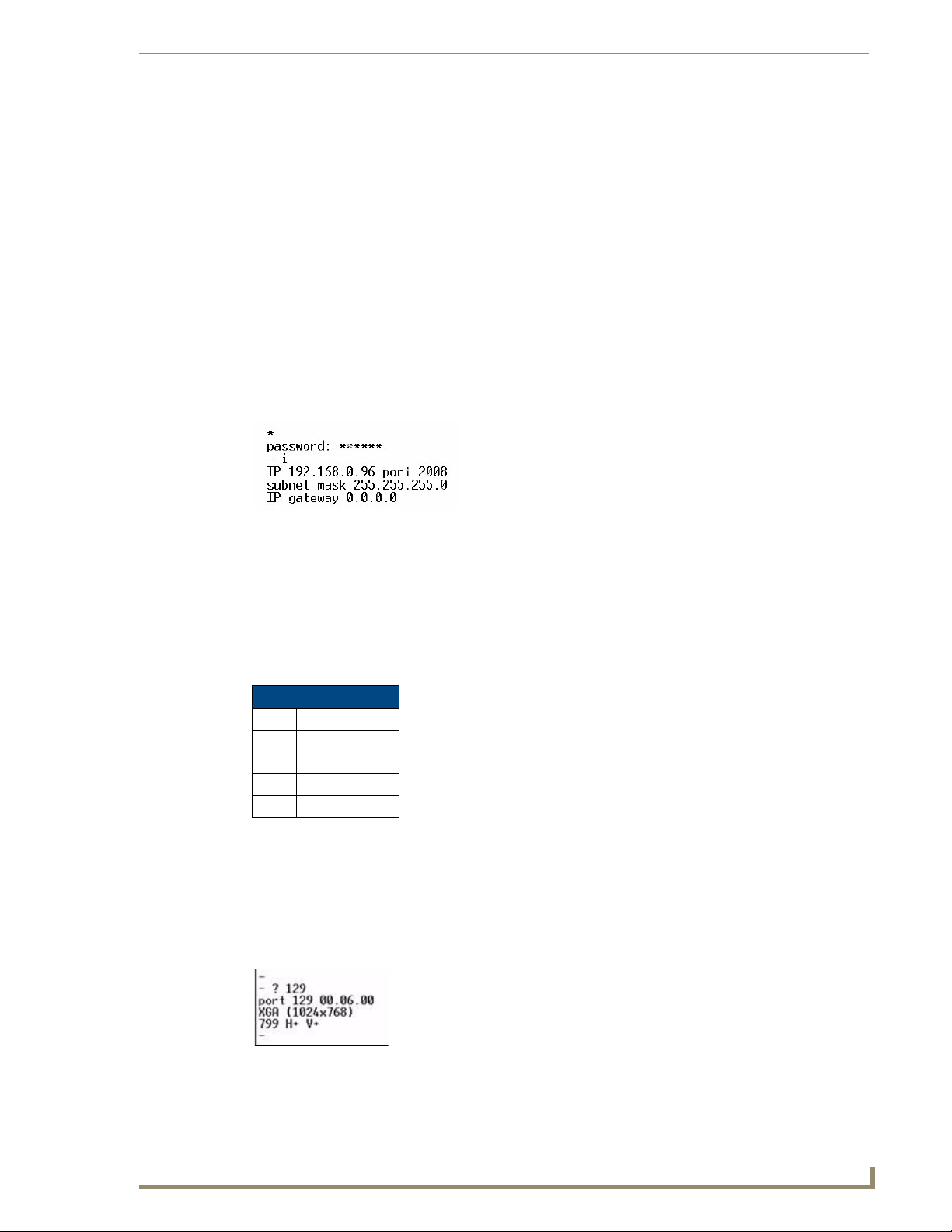
Advanced Administration
Backend Commands
In case of human error the Command Line can be used to perform several Administrative tasks on the
multi format video hub.
Changing the Login Password
Create a hyperterminal session with the UDM hub using default serial connections.
1.
2. To change the password enter the original password and new password separated by a colon at the
login prompt.
For Example type in admin:endeleo at the login prompt, to change the password from admin to
endeleo.
3. Reset the Hub. A power off then on is now required.
Obtaining the Hub’s IP Address Via the Command Line
Type i at the command prompt. (FIG. 77) Push enter.
1.
FIG. 77 Issuing the i command
Checking Port Details
Port details (resolution, port firmware) can be checked via the command line also.
Multi Format Inputs
The multi format inputs located at the rear of the Hub are numbered 129 through to 132 for
administrative purposes.
Multi format inputs
Input Input Number
A 129
B 130
C 131
D 132
1. To check the input port configuration, type in the following – a question mark followed by the Input
Number (129, 130, 131 or 132):
Example: ? 129
2. Push Enter.
3. The following information will be displayed (FIG. 78);
FIG. 78
UDM-1604 Endeleo Multi-Format Distribution Hub
Querying a multi format input port
59
Page 72
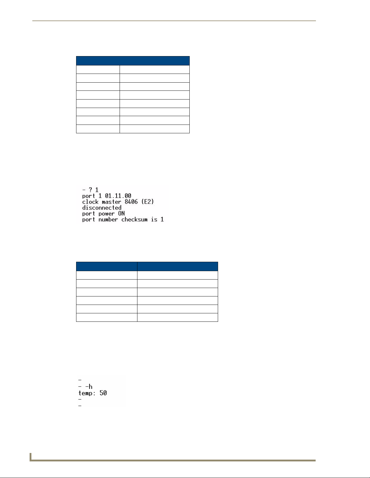
Advanced Administration
The table below describes typical values returned when using the ? command on an input port.
Multi-Format Input Configuration
Value Description
129 Input A
00.06.00 Input Controller Version
XGA Extended Graphics Array
1024x768 Screen Resolution
799 Vertical lines on screen
H+ Horizontal polarity (+/-)
V+ Vertical polarity (+/-)
User Outputs
1.
To view a port’s properties, type a question mark before the port number.
Ensure there is a space between the question mark and the number. (FIG. 79)
For example ? 1 will display Port 1 properties.
FIG. 79
Querying a port
2. Push Enter once the command has been entered.
3. The table below describes typical values returned when using the ? command on a Hub port.
Value Description
Port 1 Port number on UDM Hub
01.11.00 Port Controller version
Clock Master 8406 Master (version)
Disconnected / Connected Connected to RX
Port Power On or Off
Port Number Checksum Port in Master or Slave hub
Hub Temperature
To view the Hub’s internal temperature;
1. Connect to the UDM Hub using an appropriate tool (e.g. Hyperterminal).
2. At the command prompt type in –h to view the Hub’s internal temperature. (FIG. 80)
60
FIG. 80
Displaying the Hub temperature
UDM-1604 Endeleo Multi-Format Distribution Hub
Page 73
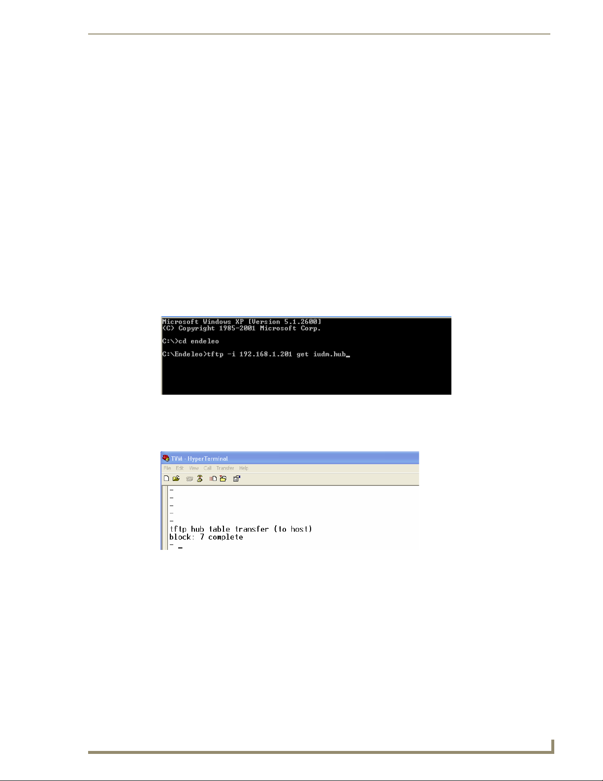
Advanced Administration
Copying IR/Serial Tables
To copy the IR/Serial tables from a UDM hub:
Windows XP Pro has a built in TFTP client program. If you are using another
operating system, or have an alternate TFTP client, follow the directions of your OS
and install TFTP client if necessary. Consult with AMX Technical Support as to the
appropriate client for your OS.
1. Run your TFTP client. If using the Windows client, move to step 2.
2. Create a folder on the C: drive named Endeleo.
3. Open a command prompt (Start, Run, type "cmd" <enter>) and change it to the C:\Endeleo
directory.
4. Connect the serial cable (RJ12 to DB9) that is supplied with the UDM Hub.
5. Open a Hyperterminal session and connect to the UDM hub (9600, 8, None,1, None)
6. Type the following command at the prompt:
TFTP -i <ip address of the udm hub> get ixxxx.hub <enter>
Example:
C:\Endeleo\TFTP -i 192.168.1.201 get iudm.hub <enter>
FIG. 81 GET iudm.hub prompt
7. After hitting Enter, you should watch the Hyperterminal session window to see the file download
from the UDM hub.
FIG. 82 File download from the UDM hub
8. The transfer is now complete.
UDM-1604 Endeleo Multi-Format Distribution Hub
61
Page 74

Advanced Administration
Endeleo UDM Receiver commands
Several Receiver-specific commands can be used for information purposes.
Viewing Video Compensation Settings
The z command will report the current compensation settings configured within the UDM Receiver.
1. Use Hyperterminal to connect to the Receiver via its serial port.
2. At the command prompt type in setup.
3. Once in setup mode to view the compensation settings, type in z. (FIG. 83)
FIG. 83 Video Compensation Settings
Resetting Video Compensation Settings
The x command resets all compensation settings at the Receiver back to default.
1. Use Hyperterminal to connect to the Receiver via its serial port.
2. At the command prompt type in setup.
3. Once in setup mode type in x to reset the compensation settings if required.
62
UDM-1604 Endeleo Multi-Format Distribution Hub
Page 75

Appendix A: Ascii / Hex Conversion
Appendix A: Ascii / Hex Conversion
Overview
Devices are typically controlled either using ascii text strings or using the HEX equivalent.
Control codes can be entered into the Endeleo hardware using ASCII, HEX or a combination of both.
(Where certain ASCII codes are difficult to enter (e.g. carriage return).
Char Hex Char Hex Char Hex Char Hex
(nul) 00 (sp) 20 @ 40 ` 60
(soh) 01 ! 21 A 41 a 61
(stx) 02 " 22 B 42 b 62
(etx) 03 # 23 C 43 c 63
(eot) 04 $ 24 D 44 d 64
(enq) 05 % 25 E 45 e 65
(ack) 06 & 26 F 46 f 66
(bel) 07 ' 27 G 47 g 67
(bs) 08 ( 28 H 48 h 68
(ht) 09 ) 29 I 49 I 69
(nl) 0a * 2a J 4a J 6a
(vt) 0b + 2b K 4b k 6b
(np) 0c , 2c L 4c l 6c
(cr) 0d - 2d M 4d m 6d
(so) 0e . 2e N 4e n 6e
(si) 0f / 2f O 4f o 6f
(dle) 10 0 30 P 50 p 70
(dc1)11131 Q51q71
(dc2) 12 2 32 R 52 r 72
(dc3) 13 3 33 S 53 s 73
(dc4) 14 4 34 T 54 T 74
(nak) 15 5 35 U 55 u 75
(syn) 16 6 36 V 56 v 76
(etb) 17 7 37 W 57 w 77
(can) 18 8 38 X 58 x 78
(em) 19 9 39 Y 59 y 79
(sub) 1a : 3a Z 5a z 7a
(esc) 1b ; 3b [ 5b { 7b
(fs) 1c < 3c \ 5c | 7c
(gs) 1d = 3d ] 5d } 7d
(rs) 1e > 3e ^ 5e ~ 7e
(us) 1f ? 3f _ 5f (del) 7f
UDM-1604 Endeleo Multi-Format Distribution Hub
63
Page 76

Appendix A: Ascii / Hex Conversion
64
UDM-1604 Endeleo Multi-Format Distribution Hub
Page 77

Appendix B – Endeleo IR Codes
Overview
The following is a list of IR Codes used by Endeleo in learning serial or IR controls for display devices.
Note that several of the items in the following table are not represented in the Action drop-down menus
for IR and Serial protocols (in the Web Configuration Interface).
For example, “AV SELECT 1" is available in the Action drop-down menu (see “A/V Sel”), and needs no
custom code reference. However, a custom command like “AV SELECT 2" would be only be accessed
by Custom 31, since this command is not represented in the Action drop-down menu options.
IR code Description IR code Description
0-9 Keys 0 to 9 52 Cursor up *
10 Channel up * 53 Cursor down *
11 Channel down * 54 Cursor left *
12 Power Off 55 Cursor right *
13 Mute 56 Esc
14 Volume up 57 Info
15 Volume down 58 Help
16 Program up 59 Teletext *
17 Program down 60 Services *
18 10+ key (for two digit channel entry) 61 Box office *
20 Channel restore (back) * 62 Interactive *
21 Power On 63 TV guide *
30 A/V select 1 64 Red *
31 A/V select 2 * 65 Green *
32 A/V select 3 * 66 Blue *
40 Device select (DVD/VCR) * 67 Yellow *
41 Enter * 70 Play
42 Clear
44 TV Input
45 TV Power
46 Live TV
47 Thumbs up
48 Thumbs down
50 Menu 80 Select pass through *
51 Select Function 81 Cancel pass through *
* 71 Pause
* 72 Stop
* 73 Record
* 74 Fast forward
* 75 Rewind
* 76 Slow *
90 -99 Custom 1... through to Custom 10
Appendix B – Endeleo IR Codes
*
An asterisk in the Description column for any IR Code in this table indicates that the
command will require custom code (since the command is not represented in the
Actions list.
UDM-1604 Endeleo Multi-Format Distribution Hub
65
Page 78

Appendix B – Endeleo IR Codes
66
UDM-1604 Endeleo Multi-Format Distribution Hub
Page 79

Appendix B – Endeleo IR Codes
DM-1604 Endeleo Multi-Format Distribution Hub
67
Page 80

It’s Your World - Take Control™
3000 RESEARCH DRIVE, RICHARDSON, TX 75082 USA • 800.222.0193 • 469.624.8000 • 469-624-7153 fax • 800.932.6993 technical support • www.amx.com
2008 AMX. All rights reserved. AMX and the AMX logo are registered trademarks of AMX. AMX reserves the right to alter specifications without notice at any time.
©
1/08
 Loading...