

Page 1

Operation/Reference Guide
UDM-0102
Endeleo Multi-Format Distribution Mini-Hub
UDM-RX02
Endeleo Multi-Format Receiver
Endeleo Distributed Media
Last Updated: 12/29/2008
Page 2

AMX Limited Warranty and Disclaimer
All products returned to AMX require a Return Material Authorization (RMA) number. The RMA number is
obtained from the AMX RMA Department. The RMA number must be clearly marked on the outside of each
box. The RMA is valid for a 30-day period. After the 30-day period the RMA will be cancelled. Any shipments
received not consistent with the RMA, or after the RMA is cancelled, will be refused. AMX is not responsible
for products returned without a valid RMA number.
Warranty Repair Policy
• AMX will repair any defect due to material or workmanship issues during the applicable warranty period at no cost to the AMX
Authorized Partner., provided that the AMX Authorized Partner is responsible for in-bound freight and AMX is responsible for
out-bound ground freight expenses.
• The AMX Authorized Partner must contact AMX Technical Support to validate the failure before pursuing this service.
• AMX will complete the repair and ship the product within five (5) business days after receipt of the product by AMX. The AMX
Authorized Partner will be notified if repair cannot be completed within five (5) business days.
• Products repaired will carry a ninety (90) day warranty or the balance of the remaining warranty, whichever is greater.
• Products that are returned and exhibit signs of damage or unauthorized use will be processed under the Non-Warranty Repair
Policy.
• AMX will continue to provide Warranty Repair Services for products discontinued or replaced by a Product Discontinuance
Notice.
Non-Warranty Repair Policy
• Products that do not qualify to be repaired under the Warranty Repair Policy due to age of the product or Condition of the product may be repaired utilizing this service.
• The AMX Authorized Partner must contact AMX Technical Support to validate the failure before pursuing this service.
• Non-warranty repair is a billable service.
• Products repaired under this policy will carry a ninety (90) day warranty on material and labor.
• AMX will notify the AMX Authorized Partner with the cost of repair, if cost is greater than the Standard Repair Fee, within five (5)
days of receipt.
• The AMX Authorized Partner must provide a Purchase Order or credit card number within five (5) days of notification, or the
product will be returned to the AMX Authorized Partner.
• The AMX Authorized Partner will be responsible for in-bound and out-bound freight expenses.
• Products will be repaired within ten (10) business days after AMX Authorized Partner approval is obtained.
• Non-repairable products will be returned to the AMX Authorized Partner with an explanation.
• See AMX Non-Warranty Repair Price List for minimum and Standard Repair Fees and policies.
Page 3

Software License and Warranty Agreement
• LICENSE GRANT. AMX grants to Licensee the non-exclusive right to use the AMX Software in the manner described in this
License. The AMX Software is licensed, not sold. This license does not grant Licensee the right to create derivative works of the
AMX Software. The AMX Software consists of generally available programming and development software, product documentation, sample applications, tools and utilities, and miscellaneous technical information. Please refer to the README.TXT file on
the compact disc or download for further information regarding the components of the AMX Software. The AMX Software is subject to restrictions on distribution described in this License Agreement. AMX Dealer, Distributor, VIP or other AMX authorized
entity shall not, and shall not permit any other person to, disclose, display, loan, publish, transfer (whether by sale, assignment,
exchange, gift, operation of law or otherwise), license, sublicense, copy, or otherwise disseminate the AMX Software. Licensee
may not reverse engineer, decompile, or disassemble the AMX Software.
• ACKNOWLEDGEMENT. You hereby acknowledge that you are an authorized AMX dealer, distributor, VIP or other AMX authorized entity in good standing and have the right to enter into and be bound by the terms of this Agreement.
• INTELLECTUAL PROPERTY. The AMX Software is owned by AMX and is protected by United States copyright laws, patent
laws, international treaty provisions, and/or state of Texas trade secret laws. Licensee may make copies of the AMX Software
solely for backup or archival purposes. Licensee may not copy the written materials accompanying the AMX Software.
• TERMINATION. AMX RESERVES THE RIGHT, IN ITS SOLE DISCRETION, TO TERMINATE THIS LICENSE FOR ANY REASON UPON WRITTEN NOTICE TO LICENSEE. In the event that AMX terminates this License, the Licensee shall return or
destroy all originals and copies of the AMX Software to AMX and certify in writing that all originals and copies have been
returned or destroyed.
• PRE-RELEASE CODE. Portions of the AMX Software may, from time to time, as identified in the AMX Software, include PRERELEASE CODE and such code may not be at the level of performance, compatibility and functionality of the GA code. The
PRE-RELEASE CODE may not operate correctly and may be substantially modified prior to final release or certain features may
not be generally released. AMX is not obligated to make or support any PRE-RELEASE CODE. ALL PRE-RELEASE CODE IS
PROVIDED "AS IS" WITH NO WARRANTIES.
• LIMITED WARRANTY. AMX warrants that the AMX Software (other than pre-release code) will perform substantially in accordance with the accompanying written materials for a period of ninety (90) days from the date of receipt. AMX DISCLAIMS ALL
OTHER WARRANTIES, EITHER EXPRESS OR IMPLIED, INCLUDING, BUT NOT LIMITED TO IMPLIED WARRANTIES OF
MERCHANTABILITY AND FITNESS FOR A PARTICULAR PURPOSE, WITH REGARD TO THE AMX SOFTWARE. THIS LIMITED WARRANTY GIVES LICENSEE SPECIFIC LEGAL RIGHTS. Any supplements or updates to the AMX SOFTWARE,
including without limitation, any (if any) service packs or hot fixes provided to Licensee after the expiration of the ninety (90) day
Limited Warranty period are not covered by any warranty or condition, express, implied or statutory.
• LICENSEE REMEDIES. AMX's entire liability and Licensee's exclusive remedy shall be repair or replacement of the AMX Software that does not meet AMX's Limited Warranty and which is returned to AMX in accordance with AMX's current return policy.
This Limited Warranty is void if failure of the AMX Software has resulted from accident, abuse, or misapplication. Any replacement AMX Software will be warranted for the remainder of the original warranty period or thirty (30) days, whichever is longer.
Outside the United States, these remedies may not available. NO LIABILITY FOR CONSEQUENTIAL DAMAGES. IN NO
EVENT SHALL AMX BE LIABLE FOR ANY DAMAGES WHATSOEVER (INCLUDING, WITHOUT LIMITATION, DAMAGES
FOR LOSS OF BUSINESS PROFITS, BUSINESS INTERRUPTION, LOSS OF BUSINESS INFORMATION, OR ANY OTHER
PECUNIARY LOSS) ARISING OUT OF THE USE OF OR INABILITY TO USE THIS AMX SOFTWARE, EVEN IF AMX HAS
BEEN ADVISED OF THE POSSIBILITY OF SUCH DAMAGES. BECAUSE SOME STATES/COUNTRIES DO NOT ALLOW
THE EXCLUSION OR LIMITATION OF LIABILITY FOR CONSEQUENTIAL OR INCIDENTAL DAMAGES, THE ABOVE LIMITATION MAY NOT APPLY TO LICENSEE.
• U.S. GOVERNMENT RESTRICTED RIGHTS. The AMX Software is provided with RESTRICTED RIGHTS. Use, duplication, or
disclosure by the Government is subject to restrictions as set forth in subparagraph ©(1)(ii) of The Rights in Technical Data and
Computer Software clause at DFARS 252.227-7013 or subparagraphs ©(1) and (2) of the Commercial Computer Software
Restricted Rights at 48 CFR 52.227-19, as applicable.
• SOFTWARE AND OTHER MATERIALS FROM AMX.COM MAY BE SUBJECT TO EXPORT CONTROL. The United States
Export Control laws prohibit the export of certain technical data and software to certain territories. No software from this Site may
be downloaded or exported (i) into (or to a national or resident of) Cuba, Iraq, Libya, North Korea, Iran, Syria, or any other country to which the United States has embargoed goods; or (ii) anyone on the United States Treasury Department's list of Specially
Designated Nationals or the U.S. Commerce Department's Table of Deny Orders. AMX does not authorize the downloading or
exporting of any software or technical data from this site to any jurisdiction prohibited by the United States Export Laws.
This Agreement replaces and supersedes all previous AMX Software License Agreements and is governed by
the laws of the State of Texas, and all disputes will be resolved in the courts in Collin County, Texas, USA. For
any questions concerning this Agreement, or to contact AMX for any reason, please write: AMX License and
Warranty Department, 3000 Research Drive, Richardson, TX 75082.
Page 4

Page 5
Important Safety Markings
Markings Used In This Manual
The following symbols are used on the UDM hardware and throughout this Installation Guide to advise
you of important instructions. All maintenance must be carried out by an AMX trained and qualified
installer.
Voltage
This symbol (FIG. 1) warns the presence of a voltage of sufficient magnitude to cause a severe or fatal
electric shock. Follow the appropriate instructions carefully to avoid the risk of injury.
FIG. 1 Voltage symbol
There are NO user serviceable parts within the UDM-0102 or UDM-RX02.
Important Safety Markings
Rating Label
The rating label, containing important safety information, is found on the underside of the UDM-0102
and UDM-RX02. Symbols used on this label are explained below;
The UDM is powered from a suitable 24 VDC supply.
FCC (Federal Communications Commission) Standards;
TESTED TO COMPLY
WITH FCC STANDARDS
FOR HOME OR OFFICE USE
This device complies with part 15 of the FCC rules.
Operation is subject to the following two conditions:
(1) This device may not cause harmful interference.
(2) This device must accept any interference received
including interference that may cause undesirable operation.
Conforms to particular European Directives.
FIG. 2 Rating Label
UDM-0102 and UDM-RX02 Operation/Reference Guide
Page 6
Important Safety Markings
Important Instructions
This symbol, used within this manual, indicates an important instruction for the
correct and safe installation, operation or maintenance of your UDM-0102 and
UDM-RX02.
Failure to comply with such instruction may result in injury to person or damage to the
UDM hardware.
Compliance
FCC and IEC
Compliance with FCC and IEC standards are found within the rating label; see above.
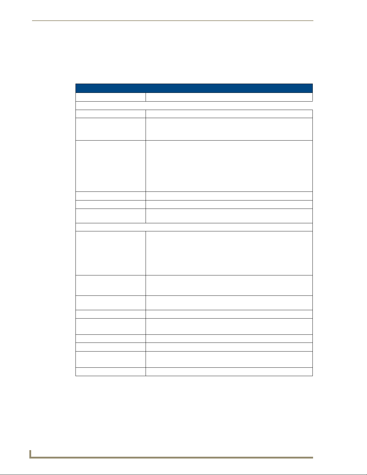
Date of Manufacture
For US customers, the date of manufacture is also found underneath the UDM-0102 and UDM-RX02.
Model Number Vendor ID Date Code
(WW/Y)
FIG. 3 Date Of Manufacture Sticker (on bottom panel)
UDM-0102/RX02 Date of Manufacture Sticker
Model Number Model number and designation, comprised of up to seven characters.
Vendor ID One- or two-character ID code.
Date Code Three-digit date code, comprised of week of year (1-52) and last digit of year.
Consecutive number Starting at “0001” and continuing to “9999”.
Consecutive Number
(4 digits)
UDM-0102 and UDM-RX02 Operation/Reference Guide
Page 7

Important Safety Markings
Environmental Conditions
The criteria on this page must be observed for the installation of the UDM-0102 and
UDM-RX02.
Temperature
DO NOT install or operate the UDM-0102 or UDM-RX02 in an area where the ambient temperature
exceeds 35ºC (95ºF) or falls below 5ºC (35ºF).
Humidity
DO NOT install or operate the UDM-0102 or UDM-RX02 in an area in which the ambient relative
humidity exceeds 85% or an area that is prone to condensation.
Water / Liquids
DO NOT install or operate the UDM-0102 or UDM-RX02 near water or in a location which may be
prone to water seepage, dripping or splashing.
DO NOT place objects containing liquids on the appliance.
The hub is not waterproof.
External use
DO NOT operate the UDM-0102 or UDM-RX02 outdoors.
UDM-0102 and UDM-RX02 Operation/Reference Guide
Page 8

Important Safety Markings
UDM-0102 and UDM-RX02 Operation/Reference Guide
Page 9

Table of Contents
Table of Contents
Important Safety Markings ................................................................................. a
Markings Used In This Manual .................................................................................. a
Voltage............................................................................................................................ a
Rating Label.............................................................................................................. a
Important Instructions .............................................................................................. b
Compliance ............................................................................................................... b
FCC and IEC .................................................................................................................... b
Date of Manufacture ....................................................................................................... b
Environmental Conditions......................................................................................... c
Temperature .................................................................................................................... c
Humidity........................................................................................................................... c
Water / Liquids................................................................................................................. c
External use ..................................................................................................................... c
UDM-0102 1x2 Multi-Format Distribution Mini-Hub ..........................................1
Overview .................................................................................................................. 1
Common Application....................................................................................................... 1
Features .......................................................................................................................... 1
Compatibility................................................................................................................... 2
Product Specifications .................................................................................................... 2
Front Panel Controls ................................................................................................. 3
SELECT Pushbutton (Switching Sources) ......................................................................... 3
PRESETS 1/2 Pushbuttons (Executing Presets)................................................................ 3
Powering The UDM-0102 On/Off.................................................................................... 3
Front Panel LEDs ...................................................................................................... 3
Power Status LED............................................................................................................ 3
Active Source LEDs ......................................................................................................... 3
Status LED....................................................................................................................... 3
UDM-0102 Wiring and Connections ...................................................................5
Overview .................................................................................................................. 5
UDM-0102 Front Panel Components ........................................................................ 5
Power LED ...................................................................................................................... 6
ETHERNET Port (RJ45).............................................................................................. 6
Pinout Configuration ....................................................................................................... 6
Default IP Address .......................................................................................................... 6
Serial (RJ12) Port ...................................................................................................... 7
Serial Port - Default Communication Settings ................................................................. 7
DB9-to-RJ12 Adapter Cable Pinouts ............................................................................... 7
UDM-0102 and UDM-RX02 Operation/Reference Guide
i
Page 10

Table of Contents
Active Input (A/B) and STATUS LEDs............................................................................... 7
SELECT and PRESETS 1/2 Pushbuttons ........................................................................... 7
UDM Port (RJ45)....................................................................................................... 8
UDM Port Pinouts ........................................................................................................... 8
UDM Port Transmission Details ....................................................................................... 8
UDM-0102 Rear Panel Components ......................................................................... 9
A/V Source Input Connectors ................................................................................... 9
VIDEO IN Connectors (HD15).......................................................................................... 9
Connecting a VGA Video Input ..................................................................................... 10
Connecting a Component Video Input .......................................................................... 10
Connecting an S-Video Input......................................................................................... 10
Connecting a Composite Video Input............................................................................ 10
Endeleo Video Adapter Cables ..................................................................................... 10
Audio & Video Formats/Resolutions/Distance............................................................... 11
IRTX (IR Transmit) Ports .......................................................................................... 11
Connecting an IR Device to an IRTX Port ...................................................................... 12
IR Receiver (IRRX) Port............................................................................................ 12
UDM-RX02 Multi-Format Receiver ....................................................................13
Overview ................................................................................................................ 13
Common Application..................................................................................................... 13
Features ........................................................................................................................ 13
UDM-RX02 Product Specifications ............................................................................... 13
Powering On the UDM-RX02 ........................................................................................ 14
UDM-RX02 Wiring and Connections .................................................................15
UDM-RX02 Front Panel Components...................................................................... 15
Rear Panel Components.......................................................................................... 15
Using an External Power Supply.................................................................................... 15
UDM Hub Port (RJ45) ............................................................................................. 15
Default IP Address ........................................................................................................ 15
SERIAL Port............................................................................................................. 16
IR Rx (IR Receiver) Port ........................................................................................... 16
Connecting an External IR Receiver Module.................................................................. 16
IR Transmit (IR Tx) Port ........................................................................................... 16
Connecting an IR Device to the IR Tx Port .................................................................... 16
AUDIO Connectors ................................................................................................. 17
VIDEO Connectors .................................................................................................. 17
VGA Connector (HD15) ................................................................................................. 17
Connecting a VGA Video Input ..................................................................................... 17
Connecting a Composite Video Input............................................................................ 17
ii
UDM-0102 and UDM-RX02 Operation/Reference Guide
Page 11

Table of Contents
Connecting an S-Video Input ........................................................................................ 17
Connecting a Component Video Input .......................................................................... 18
Connecting the UDM-RX02 Receiver to the UDM-0102 Hub.................................. 18
UDM HUB Port LEDs ..................................................................................................... 18
Video Compensation (UDM-RX02).......................................................................... 19
Serial Connection to Display Device ....................................................................... 19
RJ-11 Connection to Display Device ............................................................................. 19
Configuration ...................................................................................................21
WebConsole Overview ........................................................................................... 21
Connecting to the UDM-0102................................................................................. 21
Status Page............................................................................................................. 22
Input Configuration ....................................................................................................... 22
Configuring Audio Types For Inputs ............................................................................. 24
Selecting Inputs for Display .......................................................................................... 24
Changing an Input ......................................................................................................... 25
User Control.................................................................................................................. 25
Issuing Commands To a Selected Port .......................................................................... 26
Issuing IR Commands to Centrally Located Devices ...................................................... 27
Assigning an IR Command To an UDM-RC02 Remote Control ...................................... 28
Passthrough Mode (Inputs A – B) .................................................................................. 30
Configuring a Device for Passthrough Mode ................................................................ 30
Configuring a Port for Passthrough Mode .................................................................... 30
Using Passthrough Mode .............................................................................................. 31
Dual Output Mode ........................................................................................................ 31
Renaming the Output Ports .......................................................................................... 32
Video Compensation Guidelines ................................................................................... 32
Video Compensation - Basic Mode ............................................................................... 32
Video Compensation - Advanced Mode ........................................................................ 33
Compensating Video Via the UDM-RC10 Remote Control............................................ 34
Testing Serial Control Commands ................................................................................. 35
Examples of Serial Controls .......................................................................................... 36
Adding Centrally Located Devices ................................................................................ 37
Device Configuration and Control................................................................................. 37
Custom Controls ........................................................................................................... 37
To Issue a Custom Control ............................................................................................ 38
Setup Page ............................................................................................................. 38
Network Configuration ................................................................................................. 39
Date and Time Configuration ........................................................................................ 39
Checking the Hub Time ................................................................................................. 39
Restoring Hub Configuration and Connections on Power Up ....................................... 40
UDM-0102 and UDM-RX02 Operation/Reference Guide
iii
Page 12

Table of Contents
Hub Reset...................................................................................................................... 40
Schedule Page ........................................................................................................ 41
Scheduling an Input....................................................................................................... 41
Scheduling a Control ..................................................................................................... 43
Scheduling Events for Devices ...................................................................................... 44
Preset Scheduling.......................................................................................................... 45
Protocols Page........................................................................................................ 47
Serial Protocols ............................................................................................................. 48
IR Protocols ................................................................................................................... 48
Protocols and IR Learning .................................................................................49
Overview ................................................................................................................ 49
Creating a Serial Protocol ....................................................................................... 49
Updating the UDM-RX02 With the Serial Protocol ................................................. 51
Creating and Learning an IR Protocol ..................................................................... 51
Creating an IR Protocol ................................................................................................. 51
IR Learning With a Device’s Remote Control................................................................. 53
Updating the UDM-RX02 With the IR Protocol ....................................................... 55
Deleting Protocols .................................................................................................. 55
Advanced Administration .................................................................................57
Overview ................................................................................................................ 57
Establishing a TFTP Session with the Hub and/or Receiver .................................... 57
Determining the Current Firmware Versions .......................................................... 58
Upgrading Firmware and Web Pages On a UDM-0102 .......................................... 58
Upgrading Port Controllers .................................................................................... 59
Copying the Hub Configuration file ........................................................................ 60
Copying Protocols Between UDM-0102s................................................................ 61
Upgrading Input Controllers ................................................................................... 61
Backend Commands ............................................................................................... 62
Changing the Login Password ....................................................................................... 62
Obtaining the Hub’s IP Address Via the Command Line ............................................... 62
Setting the Hub’s IP Address Via the Command Line.................................................... 62
UDM-RX02 Commands ........................................................................................... 63
Viewing the Video Compensation Settings ................................................................... 63
Resetting Video Compensation Settings ....................................................................... 63
Appendix A: Ascii / Hex Conversion .................................................................65
Overview ................................................................................................................ 65
Appendix B – Endeleo IR Codes .......................................................................67
Overview ................................................................................................................ 67
iv
UDM-0102 and UDM-RX02 Operation/Reference Guide
Page 13

UDM-0102 1x2 Multi-Format Distribution Mini-Hub
UDM-0102 1x2 Multi-Format Distribution
Mini-Hub
Overview
The UDM-0102 (FG-UDM-0102) is designed for smaller installations with long video/audio cable runs. It
supports two high-resolution input ports and one UDM output port, making it an ideal solution for distributing
audio/video content to a classroom, conference room or other presentation room.
FIG. 1 UDM-0102
Advanced, yet cost-effective, the UDM-0102 delivers media over easily-installed, dedicated Cat5/5e/6, which
de-couples distribution of the media from the corporate backbone. Users can quickly switch and transmit any
video source to any display device, power on/off display devices, and permission user control to select and
play video sources and media servers on demand.
The UDM-0102 supports any combination of the following: two RGBHV sources, two Component
video sources, two S-Video sources or six Composite video sources.
Supported source inputs to the UDM include standard VGA, Composite, Component or S-Video feed,
and output is presented as an RJ45 port for connection to Cat5, 5e or 6 twisted-pair Ethernet cable.
Video inputs are connected via the HD15 VIDEO IN Input connectors on the rear of the UDM. Adapters
are used to bring the different types of video source into the UDM.
To use Component or Composite input, you will need the Endeleo HD-15 to 3x RCA
Breakout Cable: UDM-HD15RCA3F (FG-HD15RCA3F, not included).
To use SVideo input, you will need the Endeleo HD-15 to S-Video Cable Breakout Cable:
UDM-SVID01 (FG-UDM-SVID01, not included).
Each UDM has an Ethernet network port to provide connectivity to a central management system, or can
be controlled by the onboard configuration pages. A Serial connection is also provided for CLI
administration and diagnostic purposes.
The UDM-0102 can deliver all content and control up to 2300 feet. See the Audio & Video Formats/
Resolutions/Distance section on page 11 for tested and confirmed distances.
Common Application
Ideal for distributing audio/video content to classrooms, conference rooms or other presentation rooms.
Features
2 multi-format inputs x 1 RJ-45 output
Digital audio support
Central device control
Switched manually, centrally (browser) and/or via remote control
UDM-0102 and UDM-RX02 Operation/Reference Guide
1
Page 14
UDM-0102 1x2 Multi-Format Distribution Mini-Hub
Compatibility
The UDM-0102 is compatible for use with UDM-RX02 (FG-UDM-RX02) Endeleo Multi-Format Receivers.
See the UDM-RX02 Multi-Format Receiver section on page 13 for details.
Product Specifications
UDM-0102 Specifications
Power Requirements: 24VDC @ .75A
Front Panel Components
Ethernet (RJ-45) port: Provides 10 BaseT network connectivity
Serial (RJ-12) port
(labelled “10101”):
LEDs: The front LEDs are grouped by control type and are labeled according to their
SELECT (A/B) Pushbutton: Pushbutton switches between Source A / Source B.
PRESETS (1/2) Pushbuttons: Two pushbuttons execute user-defined presets.
UDM (RJ-45) port: Provides audio/video transport as well as control via Cat5, Cat5e or Cat6 to a
Rear Panel Connectors:
Source Inputs (A, B): Two sets of input connectors for A/V source devices (labelled A and B):
IRTX Ports: Two 3.5mm stereo IR Transmitter output ports allow up to two IR-controlled
IRRX Port: 3.5mm stereo input port, allows connecting an IR receiver to allow learning IR
Power Socket: 2.1mm barrel-style DC power socket (female)
Operating Environment: • 35°F - 95°F (5°C - 35°C)
Dimensions (HWD):
Weight:
Certifications: • CE
Included Accessories: Power Supply, 24VDC, 750 mA with cable (FG-UDM-PS)
Enables an administrator to control the various functions to the UDM-0102
from a command line prompt and terminal connection.
Requires a DB9-to-RJ12 adapter cable (FG-RS01) to connect to a PC.
corresponding port (connector) numbers on the rear of the unit.
• Power - device is receiving power
• A - Source A is currently selected
• B - Source B is currently selected
• Status - changes from red to green when it receives a valid UDP command,
and returns to red after 30 seconds if it has not received anything.
UDM-RX02 Receiver.
• VIDEO IN: HD-15 input connector (female) - supports VGA, Component, SVideo and Composite formats.
• Analog Audio: Left (white) and Right (red) stereo RCA input connectors
(female).
• Digital Audio: SPDIF (female) input connector.
devices (such as a DVD or VCR player) to be controlled via optional wired IR
emitters.
commands.
• Max. relative humidity - 85% (non-condensing)
• 1.61" x 8.63" x 3.66" (40.89 mm x 219.08 mm x 93.04 mm)
• 1.60 lb. (730 g)
• FCC part 15 Class A
2
UDM-0102 and UDM-RX02 Operation/Reference Guide
Page 15
UDM-0102 1x2 Multi-Format Distribution Mini-Hub
UDM-0102 Specifications (Cont.)
Other AMX Equipment: • Endeleo HD-15 to S-Video Cable (FG-UDM-SVID01)
• Endeleo HD-15 to 3x RCA Breakout Cable (FG-HD15RCA3F)
• RS232 DB9/RJ12 Connection Cable (FG-RS01)
• UDM-RX02 Endeleo Multi-Format Receiver (FG-UDM-RX02)
• UDM-RC10 Endeleo Multi-Format IR Engineering Remote Control
(FG-UDM-RC10)
• UDM-RC02 Multi-Format IR Remote Control (FG-UDM-RC02)
• IR Emitter Module (FG-IR01)
• External IR Receiver Module (FG-IR03)
Front Panel Controls
SELECT Pushbutton (Switching Sources)
The UDM-0102 supports 2 AV input sources that can be switched manually.
To switch the inputs at the device, press the SELECT pushbutton on the front of the device.
PRESETS 1/2 Pushbuttons (Executing Presets)
The UDM-0102 supports a total of 2 presets.
1. Select the AV input source (1 or 2), via the SELECT pushbutton.
2. Select either PRESET 1 or PRESET 2 to execute.
Powering The UDM-0102 On/Off
Powering on the Hub: Insert the barrel connector of the power supply into the power
connector on the UDM.
Powering off the Hub: Remove the barrel connector of the power supply from the power
connector on the UDM.
Front Panel LEDs
Power Status LED
Yellow LED on front panel indicates unit is powered.
Active Source LEDs
The front LEDs are grouped by control type and are labeled according to their corresponding port
(connector) numbers on the rear of the unit.
A - Source A is currently selected
B - Source B is currently selected
Status LED
This LED changes from red to green when it receives a valid UDP command, and returns to red after 30
seconds if it has not received anything.
UDM-0102 and UDM-RX02 Operation/Reference Guide
3
Page 16

UDM-0102 1x2 Multi-Format Distribution Mini-Hub
4
UDM-0102 and UDM-RX02 Operation/Reference Guide
Page 17

UDM-0102 Wiring and Connections
UDM-0102 Wiring and Connections
Overview
The system diagram in FIG. 2 illustrates a basic installation using the UDM-0102 Hub, UDM-RX02
receivers, and attached display and audio playback devices:
LCD
UDM-RX02
UDM-0102
UDM-RC02
Ethernet
Serial
Audio/Video
Cat5
IR Control
SWT
FIG. 2 UDM-0102 System Diagram
UDM-0102
Internet
UDM-0102 Front Panel Components
FIG. 3 shows the components on the front panel of the UDM-0102:
HDTV Satellite Receiver
Laptop
ETHERNET port (RJ45)
Power LED
Active input (A/B) LED
FIG. 3 UDM-0102 - front panel components
UDM-0102 and UDM-RX02 Operation/Reference Guide
Serial port (RJ12)
Source
Select
button
Preset buttons (1/2)
Status LED
RJ45 port for connection
to an UDM-RX02 Receiver
5
Page 18
UDM-0102 Wiring and Connections
Power LED
Refer to the Front Panel LEDs section on page 3 for descriptions of the front panel LEDs.
ETHERNET Port (RJ45)
The RJ45 port on the front panel of the UDM (labelled “ETHERNET”) provides 10 BaseT network
connectivity.
Pinout Configuration
The following table lists the pinouts, signals, and pairing for the Ethernet port.
RJ45 Ethernet Port Pinouts and Signals
Pin Signals Connections Pairing Color
1 TX + 1 --------- 1 1 --------- 2 Orange-White
2 TX - 2 --------- 2 Orange
3 RX + 3 --------- 3 3 --------- 6 Green-White
4 no connection 4 --------- 4 Blue
5 no connection 5 --------- 5 Blue-White
6 RX - 6 --------- 6 Green
7 no connection 7 --------- 7 Brown-White
8 no connection 8 --------- 8 Brown
FIG. 4 diagrams the pinouts and signals for the Ethernet RJ45 connector and cable.
RJ45 wiring diagram
FIG. 4
Consult the Network Administrator for correct cabling from the UDM-0102 onto the
network. For remote connectivity, the Firewall may have to be configured to open port
2008 for remote connectivity over UDP
Default IP Address
The default IP address of the UDM-0102 is 192.168.0.96.
Once the UDM-0102 is switched on, use the Setup option in the UDM WebConsole to configure the
Hub’s correct IP address (see the Setup Page section on page 38).
The IP address may also be configured via the serial port (refer to the Backend Commands section on
page 62).
6
UDM-0102 and UDM-RX02 Operation/Reference Guide
Page 19
UDM-0102 Wiring and Connections
Serial (RJ12) Port
Connecting the Serial port on the UDM-0102 is not an essential step in the
installation process.
The SERIAL (RJ12) port on the front panel (labelled “10101”) is available for diagnostic and
troubleshooting purposes.
The Serial port on the UDM-0102 requires a DB9-to-RJ12 adapter cable (FG-RS01, not included) to
connect to a PC for Terminal control.
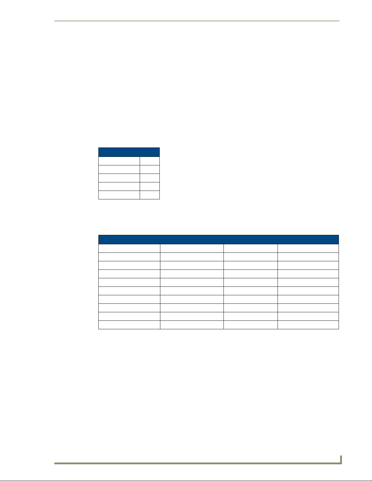
Serial Port - Default Communication Settings
Use hyper terminal with default serial settings to communicate with the UDM-0102 (and UDM-RX02):
Default Serial Settings
Baud Rate: 9600
Data Bits: 8
Parity: None
Stop B its: 1
Flow Control: None
DB9-to-RJ12 Adapter Cable Pinouts
The following table provides the pinout configuration for the DB9-to-RJ12 (FG-RS01, not included)
adapter cable (:
DB9-to-RJ12 Adapter Cable Pinouts
DB9 connector Function Abbreviation RJ12 connector
Pin 1 Not used NC
Pin 2 Transmit Data TD or TX or TXD Pin 1
Pin 3 Receive Data RD or RX or RXD Pin 2
Pin 4 Data Set Ready DSR Pin 3
Pin 5 Signal Ground GND Pin 4
Pin 6 Data Terminal Ready DTR Pin 5
Pin 7 Not Used NC Pin 6
Pin 8 Not Used NC
Pin 9 Not Used NC
Active Input (A/B) and STATUS LEDs
Refer to the Front Panel LEDs section on page 3 for descriptions of the front panel LEDs.
SELECT and PRESETS 1/2 Pushbuttons
Refer to the Front Panel Controls section on page 3 for descriptions of the front panel control
pushbuttons.
UDM-0102 and UDM-RX02 Operation/Reference Guide
7
Page 20
UDM-0102 Wiring and Connections
UDM Port (RJ45)
The RJ45 port on the front panel of the UDM-0102 labelled “UDM” provides connectivity to a UDMRX02 Multi-Format Receiver. This is a standard RJ45 connector, and the UDM-RX02 can be connected
via either Cat5, Cat5e or Cat6 cabling.
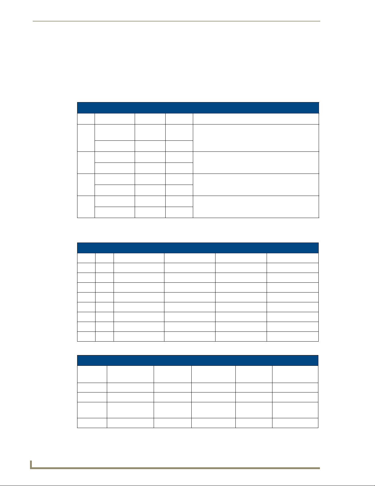
UDM Port Pinouts
The following table describes the pinout configuration of the UDM port:
UDM Port Pinouts
Pair Color RJ45 Pin Polarity Endeleo Function
White / Blue 5 -
1
Blue 4 +
White / Orange 1 +
2
Orange 2 -
White / Green 3 +
3
Green 6 -
White / Brown 7 +
4
Brown 8 -, Gnd
Green
Red
Blue
Bi-Directional Control, Digital Audio, Phantom Power
UDM Port Transmission Details
The following table provides transmission details for the UDM port:
Transmission on UDM Port
Pair Pin UDM (CVBS) UDM (SVideo) UDM (YPbPr) UDM (RGB)
1 1 CVBS + Luma + Y+ Red +
1 2 CVBS - Luma - Y- Red -
2 3 Chroma + Pr+ Blue+
3 4 Pb+ Green +
3 5 Pb- Green -
2 6 Chroma - Pr- Blue -
4 7 Power, Data, Audio Power, Data, Audio Power, Data, Audio Power, Data, Audio
4 8 Power, Data, Audio Power, Data, Audio Power, Data, Audio Power, Data, Audio
An incorrectly terminated cable will result in the following scenarios:
Incorrectly terminated cable results
Pair Composite
Video
1 No Video 1 No Luma No Y No RED LIT
2 No Video 3 No Chroma No Pr No BLUE LIT
3 No Video 2 NONE No Pb NONE No GREEN
4
SVideo Component
Video
NONE
RGBHV
Video
User Port
LINK LED
LIT NONE
8
UDM-0102 and UDM-RX02 Operation/Reference Guide
Page 21
UDM-0102 Rear Panel Components
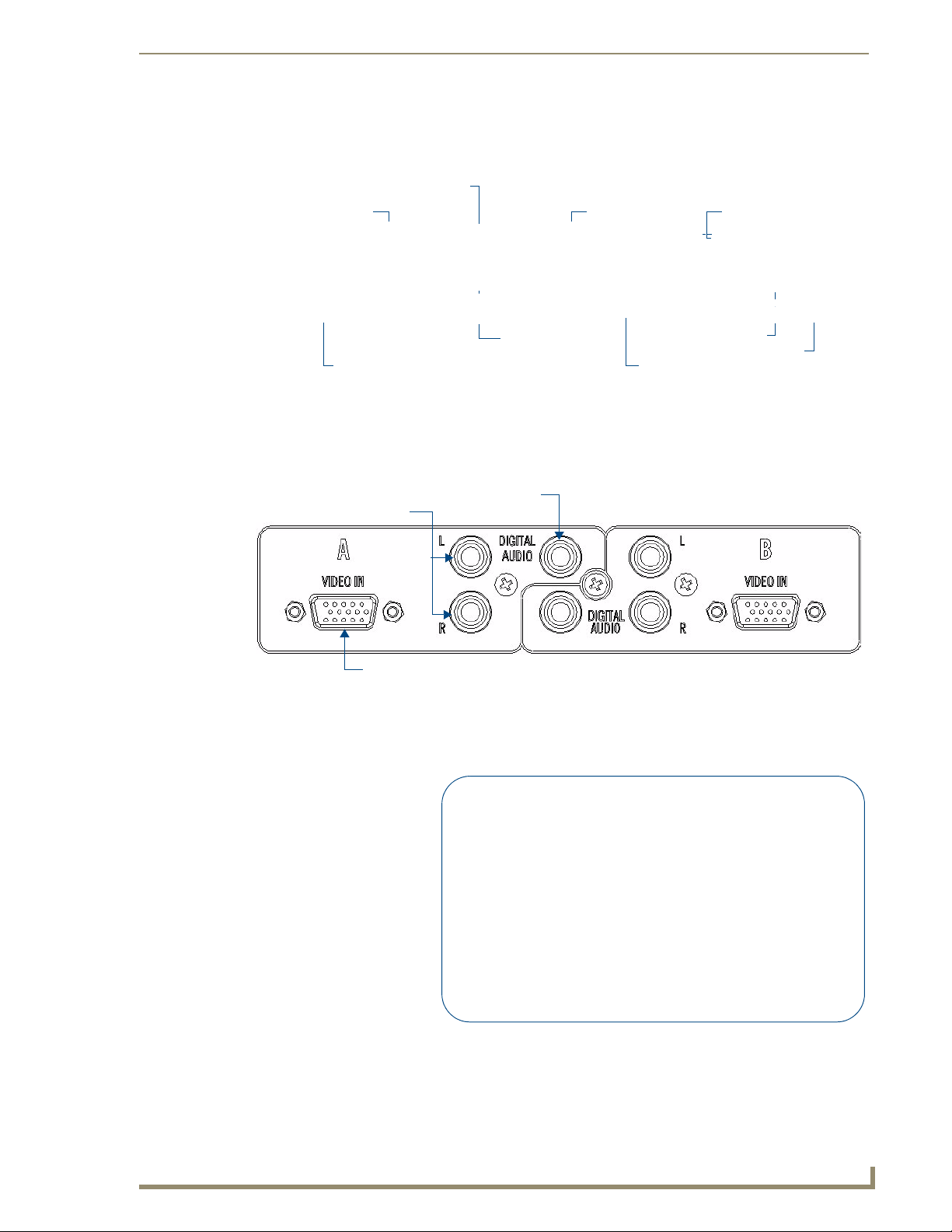
FIG. 5 shows the components on the rear panel of the UDM-0102:
SPDIF Digital Audio
connector (A)
RCA Audio (A) RCA Audio (B)
UDM-0102 Wiring and Connections
IRTX ports
SPDIF Digital Audio
HD15 female connector (A) HD15 female connector (B)
connector (B)
IRRX port
Power connector
FIG. 5 UDM-0102 - rear panel components
A/V Source Input Connectors
There are two sets of input connectors to the rear panel of the UDM-0102, labelled A and B (FIG. 6).
Digital Audio Input (SPDIF)
RCA Audio Inputs (L/R)
Video Input (female HD15)
FIG. 6 A/V Source Input connectors
VIDEO IN Connectors (HD15)
FIG. 7 provides the pin layout for the VIDEO IN HD15 Connectors:
12345
678910
1112131415
FIG. 7 VIDEO IN HD15 Connector
UDM-0102 and UDM-RX02 Operation/Reference Guide
Input Pin
1
2
3
4
5
6
7
8
9
10
11
12
13
14
15
VGA
Red
Green
Blue
n/c
n/c
Red - Ground
Green - Ground
Blue - Ground
n/c
n/c
n/c
n/c
Horz. Synch
Vert. Sy nch
n/c
HD15 Pinouts
Component
Y
Pb
Pr
n/c
n/c
Y - Ground
Pb - Ground
Pr - Ground
n/c
n/c
n/c
n/c
n/c
n/c
n/c
S-Video
Luminance
n/c
Chrominance
n/c
n/c
Luminance - Ground
n/c
Chrominance - Ground
n/c
n/c
n/c
n/c
n/c
n/c
n/c
Composite
CVBS1
CVBS2
CVBS3
n/c
n/c
CVBS1 - Ground
CVBS2 - Ground
CVBS3 - Ground
n/c
n/c
n/c
n/c
n/c
n/c
n/c
9
Page 22

UDM-0102 Wiring and Connections
The UDM-HD15RCA3F Endeleo HD15 to 3x RCA Breakout Cable
(FG-HD15RCA3F) referenced in the table above is different from a standard RCA
cable, and an RCA cable cannot be used in its place (the Y, Pb, and Pr connections
are shifted from the VESA standard). If a standard cable is to be used, you will have
to swap the connectors. Contact AMX Technical Support for details.
Connecting a VGA Video Input
1.
Connect one end of a VGA cable to the source device’s VGA output port.
2. Attach the other end of the cable to the appropriate VIDEO IN connection (A or B) on the UDM.
For example, connect to the Video In connection on Input A of the Hub.
3. Connect any audio to the analog (RCA) audio connectors or digital (SPDIF) connector.
Ensure Input A is configured as a “VGA Input” and named appropriately within the
“Inputs” section of the UDM’s built-in WebConsole. Also ensure the correct Audio
Type (Analog L/R or S/PDIF) is selected for the relevant input. Refer to the
Configuration section on page 21 for details.
Connecting a Component Video Input
Connect the UDM-HD15RCA3F Breakout Cable (FG-HD15RCA3F, not included) to the video
1.
source device’s Component video output connectors (Red, Green and Blue).
2. Attach the other end of the cable to the appropriate VIDEO IN connection (A or B) on the UDM.
3. Connect any audio to the analog (RCA) audio connectors or digital (SPDIF) connector.
Connecting an S-Video Input
1.
Connect the UDM-SVID01 HD15 to SVideo cable (FG-UDM-SVID01, not included) to the video
source’s S-Video connection.
2. Attach the other end of the cable to the appropriate VIDEO IN connection (A or B) on the UDM.
3. Connect any audio to the analog (RCA) audio connectors or digital (SPDIF) connector.
Connecting a Composite Video Input
1.
Connect the UDM-HD15RCA3F Breakout Cable (FG-HD15RCA3F, not included) to the source
device’s Composite output ports:
A1 = red RCA
A2 = green RCA
A3 = blue RCA
2. Attach the other end of the cable to the appropriate VIDEO IN connection (A or B) on the UDM.
3. Connect any audio to the analog (RCA) audio connectors or digital (SPDIF) connector.
Endeleo Video Adapter Cables
The following adapter cables are available from AMX, to allow connecting various video input types to
the UDM-0102:
Endeleo Adapter Cables
Name FG # Description
UDM-HD15RCA3 FG-HD15RCA3 Endeleo HD-15 to 3x RCA Breakout Cable
UDM-SVID01 FG-UDM-SVID01 Endeleo HD-15 to S-Video Cable Breakout Cable
10
UDM-0102 and UDM-RX02 Operation/Reference Guide
Page 23
UDM-0102 Wiring and Connections
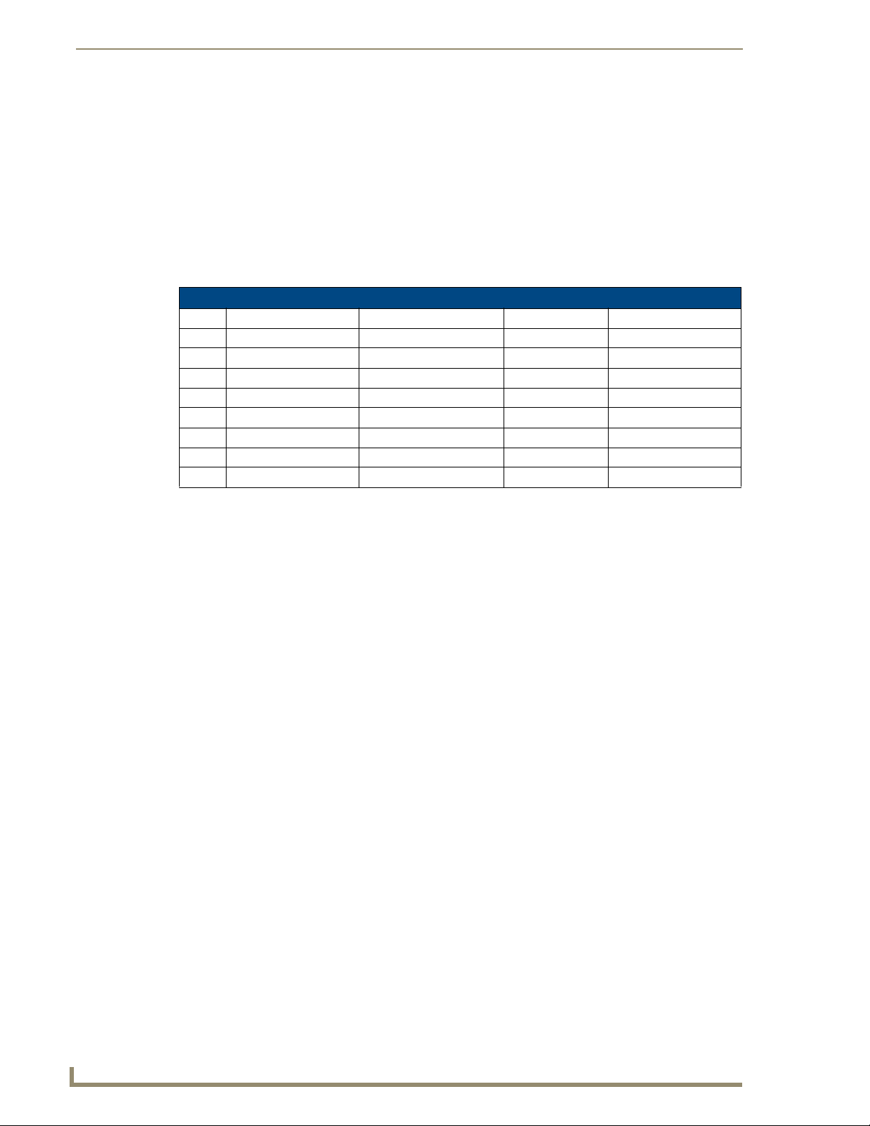
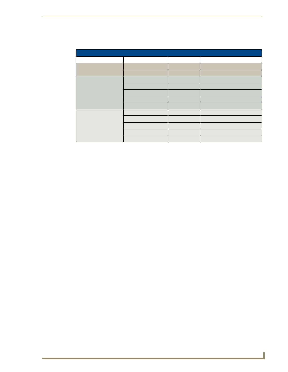
Audio & Video Formats/Resolutions/Distance
The following table provides allowed distances for video cable runs of various classes and formats: l
Audio & Video Formats/Resolutions/Distance
Class Format Name Max Distance
Composite 720x480 NTSC 2300’ (700m)
720x756 PAL 2300’ (700m)
Component 720x480 480p 2300’ (700m)
720x756 576p 2300’ (700m)
1280x720 720p 650’ (200m)
1920x1080 1080i 500’ (150m)
1920x1080 1080p 400’ (120m)
VGA 640x480 VGA 650’ (200m)
800x600 SVGA 650’ (200m)
1024x768 XGA 650’ (200m)
1280x1024 SXGA 500’ (150m)
1600x1200 UXGA 400’ (120m)
It is important to note that the maximum distances indicated above are not absolute, but are recommended
distances that have been tested to deliver video at the specified resolutions, without significant signal
degradation. In particular, lower resolutions (640 x 480, 720 x 480 and 800 x 600) can often be delivered
significantly further than what is indicated in the table.
Several factors affect the overall quality of the displayed video, including the quality of the twisted pair cable
and connectors used, the nature of the video image itself, as well as the particulars of the installation and how
the video is displayed and viewed.
Two major factors affect the quality of signal transmission include:
Cable Distance: Naturally, long distance cable runs (in excess of 300 meters/1000 feet) are always
subject to resistance and capacitance losses which can negatively impact the quality of the image.
Skew: "Skew" represents the slight delay that results from the variation in wiring lengths for each
of the twisted pairs. The effects of skew on A/V signals increases with cable length. Excessive skew
can adversely affect video image quality, especially at long cable lengths and high signal
resolutions.
IRTX (IR Transmit) Ports
Two 3.5mm stereo IRTX connections issue IR commands from the UDM hub to the controlled device(s):
IRTX1 – Transmits IR commands to Device 1
IRTX2 – Transmits IR commands to Device 2
A maximum of two IR devices (such as DVD players or VCRs) can be connected to the UDM via the
IRTX ports on the rear panel (FIG. 8), and controlled via the WebConsole or remote control.
UDM-0102 and UDM-RX02 Operation/Reference Guide
11
Page 24
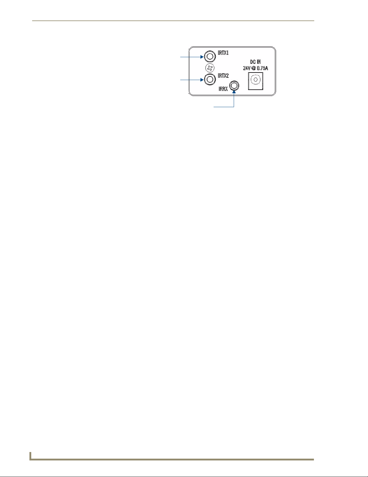
UDM-0102 Wiring and Connections
IRTX1 IR Transmitter port (3.5mm stereo output)
IRTX2 IR Transmitter port (3.5mm stereo output)
FIG. 8 IR Transmit/Receive Ports
IR devices controlled via the IRTX ports are typically installed within the same
equipment rack as the UDM.
Connecting an IR Device to an IRTX Port
To issue IR commands to the display device such as power on or power off, an IR01 Endeleo IR Emitter
Module (FG-IR01) is needed:
IRRX IR Receiver port (3.5mm stereo input)
FIG. 9 IR01 Endeleo IR Emitter Module
Ensure the position of the device corresponds to the position assigned in the Devices
option of the UDM-0102’s WebConsole.
1. Connect the IR Emitter Module cable to the appropriate IRTX port on the UDM-0102.
2. Run the other end of the cable to the display device, and attach the IR Emitter over the device’s IR
sensor by removing the cover on the reverse side of the IR Emitter.
3. The UDM-0102 is now capable of issuing IR commands to the display device.
IR commands for each device on the system have to be learned by the UDM-0102 in order to function
properly. Refer to the Protocols and IR Learning section on page 49 on how to learn a device’s IR
commands.
IR Receiver (IRRX) Port
The IR RX port has two purposes:
It is used for devices utilizing Passthrough Mode. Refer to the Passthrough Mode (Inputs A –
B) section on page 30 for information.
Also used for learning and creating new IR protocols. Refer to the Creating and Learning an
IR Protocol section on page 51 for details.
12
UDM-0102 and UDM-RX02 Operation/Reference Guide
Page 25
UDM-RX02 Multi-Format Receiver
Overview
Installed at the display device, the UDM-RX02 (FG-UDM-RX02) converts the signal received from the
UDM-1604 or UDM-0102 Multi-Format Distribution Hub to standard audio/video signals (FIG. 10).
FIG. 10 UDM-RX02
The UDM-RX02 includes support for Common Mode Sync, found in the latest display devices, to synchronize
color images being displayed. The UDM-RX02 also allows an optional local power supply to be added for
long cable runs. With intelligent receiver technology, each UDM-RX02 is powered remotely from the MultiFormat Distribution Hub via the Cat 5, 5e or 6 cable. As the hub is switched from one video/audio source to
another, the receiver detects a change in signal and automatically switches the Plasma or LCD screen to its
new video format.
Distances of 1,000 feet/300 meters are supported at 1280x1024; higher resolutions are supported at shorter
distances.
UDM-RX02 Multi-Format Receiver
Common Application
Perfect for the receiving end of sources to be displayed in classrooms, conference rooms or other presentation
rooms.
Features
Video Support for 1600 x 1200 (UXGA), 1920 x 1080 (HDTV), Component (Y/Pb/Pr), S-Video,
CVBS-PAL/NTSC
S/PDIF, Digital and analog stereo audio support
IR blaster and receiver ports
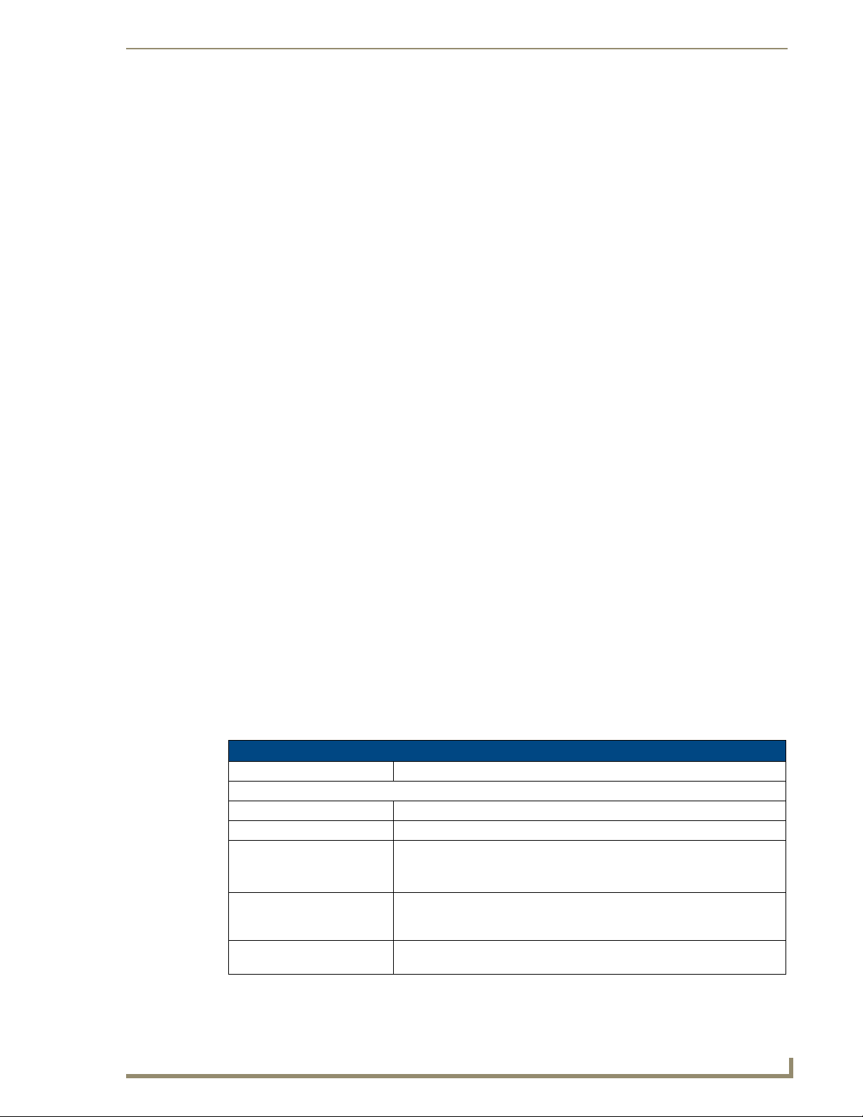
UDM-RX02 Product Specifications
UDM-RX02 Specifications
Power Requirements: 24VDC @ .75A
Rear Panel Connectors:
Power Socket: 2.1mm barrel-style DC power socket (female)
UDM Hub Port: Provides audio/video transport via Cat5, Cat5e or Cat6 to an UDM-0102 Hub.
Serial (RJ12) port: Enables an administrator to control the various functions to the UDM-RX02
from a command line prompt and terminal connection.
Requires a DB9-to-RJ12 adapter cable (FG-RS01) to connect to a PC.
IR Rx Port: 3.5mm stereo input port, for connection of an IR receiver to allow setup of the
IR Tx Port: 3.5mm stereo IR Transmitter output port allows one IR-controlled device
UDM-RX02, local compensation controls, and remote control of centrally
located IR devices.
(such as a DVD or VCR player) to be controlled via optional wired IR emitter.
UDM-0102 and UDM-RX02 Operation/Reference Guide
13
Page 26

UDM-RX02 Multi-Format Receiver
UDM-RX02 Specifications (Cont.)
Audio Connectors: • Black RCA female connector - Digital audio
Video Connectors: • Yellow RCA female connector - CVBS (supports composite video)
Operating Environment: • 35°F - 95°F (5°C - 35°C)
Dimensions (HWD):
Weight:
Certifications: • CE
Other AMX Equipment: • RS232 DB9/RJ12 Connection Cable (FG-RS01)
• White RCA female connector - Analog audio Left
• Red RCA female connector - Analog audio Right
• S-Video - S-video female connector
• VGA - HD15 female connector (supports VGA video)
• Green RCA female connector - Component output: Y
• Blue RCA female connector - Component output: Pb
• Red RCA female connector - Component output: Pr
• Max. relative humidity - 85% (non-condensing)
• 1" x 8 15/16" x 3 3/8” (25 mm x 227 mm x 85 mm)
• 1.45 lb. (658 g)
• FCC part 15 Class A
• UDM-RC02 Multi-Format IR Remote Control (FG-UDM-RC02)
• IR01 IR Emitter Module (FG-IR01)
• IR03 External IR Receiver Module (FG-IR03)
• UDM-PS 24VDC, 750mA Power Supply (FG-UDM-PS)
Powering On the UDM-RX02
As a Class 1 appliance, ensure the device is connected to a main socket outlet with a
protective grounding connection.
The UDM-RX02 may be powered by its hub device through a standard CAT5 cable, but it may also be
powered through an optional 24 VDC power supply (FG-UDM-PS) intended to augment power for very
long cable runs. To connect the UDM-RX02 to the optional power supply, insert the barrel connector of
the power supply into the power connector on the UDM-RX02 (illustrated in FIG. 1).
To power down the UDM-RX02, remove the barrel connector of the power supply from the power
connector and then remove the Ethernet cable from the UDM Hub connector.
Disconnecting the optional power supply will not power down the UDM-RX02 if its
Ethernet connection to the UDM Hub is intact. Remove the CAT5 cable from the
device, powering the unit down then add the power supply and reconnect the CAT5.
14
UDM-0102 and UDM-RX02 Operation/Reference Guide
Page 27

UDM-RX02 Wiring and Connections
UDM-RX02 Wiring and Connections
UDM-RX02 Front Panel Components
There are no components on the front panel of the UDM-RX02 (FIG. 11).
FIG. 11 UDM-RX02 - front panel
Rear Panel Components
All of the connectors and ports are located on the rear panel of the UDM-RX02 (FIG. 12):
Composite (Pr) port
UDM HUB port (RJ45) - from an
“OUTPUT” port on the UDM-0102
Serial port (RJ12)
CVBS port
VGA (HD15) port
S-Video port
Composite (Pb) port
Composite (Y) port
IR Rx port
IR Tx port
Power connector
FIG. 12 UDM-RX02 - rear panel components
RCA audio
(left/right)
SPDIF female Digital Audio port
Using an External Power Supply
Normally, the UDM-RX02 is powered remotely by the UDM-0102 Hub. However, in some cases
involving very long cable runs, it may be necessary to power the RX02 via the UDM-PS power supply.
The best way to determine wether the external power supply is needed is to observe the image received.
If there is noticeable distortion, then adding an external power supply may give a visible improvement.
Generally, the quality of image received depends mainly on distance and resolution.
Typically, the external power supply is not needed for cable runs of approximately 650’ (200m) or less,
but at greater distances it may improve image quality.
UDM Hub Port (RJ45)
The UDM-RX02 connects to the network through a connection to a UDM-0102 Hub. Refer to the UDM0102 Multi-Format Distribution Hub Operation/Reference Guide (available at www.amx.com) for
information on connecting the UDM-0102 to the network.
Refer to the Pinout Configuration section on page 6 for details.
Default IP Address
The default IP address of the UDM-RX02 is 192.168.0.96.
UDM-0102 and UDM-RX02 Operation/Reference Guide
15
Page 28

UDM-RX02 Wiring and Connections
Once the UDM-RX02 is switched on, use the Setup option in the UDM Browser Interface to configure
the Hub’s correct IP address.
The IP address may also be configured directly on the UDM-RX02, via the Serial port (refer to the
Backend Commands section on page 62).
SERIAL Port
The SERIAL port is available for diagnostic and troubleshooting purposes.
The Serial port on the UDM-RX02 is an RJ12 connector, and requires a DB9-to-RJ12 adapter cable (FGRS01) to connect to a PC for Terminal control.
Refer to the Serial (RJ12) Port section on page 7 for pinout and transmission details.
IR Rx (IR Receiver) Port
The IR Rx port (see FIG. 12 on page 15) is used for creating new IR protocols, for use with centrallylocated IR devices.
Refer to the Protocols and IR Learning section on page 49 for details.
Connecting an External IR Receiver Module
If pass-through mode (where a device such as a DVD or VCR can be controlled via an Endeleo RC-02
remote control) is required then an IR03 Endeleo External IR Receiver Module will be needed to pick up
IR controls from the remote control.
Alternatively if the UDM-RX02 is to be compensated via a remote control, then an IR Receiver Module
is also needed.
IR Transmit (IR Tx) Port
The IR Tx port (see FIG. 12 on page 15) issues IR commands from the UDM-RX02 to a controlled
device. One IR device (such as DVD player or VCR) can be connected to the UDM-RX02 via the IR Tx
port, and controlled via the UDM-0102’s WebConsole or via remote control.
IR devices controlled via the IRTX ports are typically installed within the same
equipment rack as the UDM-RX02.
Connecting an IR Device to the IR Tx Port
To issue IR commands to the display device such as power on or power off, an IR01 Endeleo IR Emitter
Module (FG-IR01) is needed.
Ensure the position of the device corresponds to the position assigned in the Devices
option of the UDM-0102’s WebConsole.
1. Connect the IR Emitter Module cable to the IR Tx connector on the UDM-RX02.
2. Run the other end of the cable to the display device, and attach the IR Emitter over the device’s IR
sensor by removing the cover on the reverse side of the IR Emitter.
3. The UDM-RX02 is now capable of issuing IR commands to the display device.
IR commands for each device on the system have to be learned by the UDM-0102 in order to function
properly. Refer to the Protocols and IR Learning section on page 49 on how to learn a device’s IR
commands.
16
UDM-0102 and UDM-RX02 Operation/Reference Guide
Page 29

UDM-RX02 Wiring and Connections
AUDIO Connectors
The UDM-RX02 provides standard Audio RCA output connectors for S/PDIF for digital audio, and
LEFT/RIGHT for analog audio output (see FIG. 12 on page 15).
VIDEO Connectors
VGA Connector (HD15)
FIG. 13 provides the pin layout for the VGA connector:
12345
67891
1112131415
FIG. 13 VGA (HD15) Connector
Refer to VIDEO IN Connectors (HD15) section on page 9 for pinout details.
Connecting a VGA Video Input
Attach one end of the Endeleo VGA to VGA cable to the VGA connector on the UDM-RX02 (see
1.
FIG. 12 on page 15).
2. Run the other end to the VGA connector on the display device. Connect firmly.
3. If appropriate connect audio to the audio connectors on the UDM-RX02.
Ensure Input A is configured as a “VGA Input” and named appropriately within the
“Inputs” section of the Hub’s Configuration software. Also ensure the correct Audio
Type (Analog L/R or S/PDIF) is selected for the relevant input.
Connecting a Composite Video Input
1.
Attach the composite cable (normally yellow) to the CVBS connector on the UDM-RX02 (see
FIG. 12 on page 15).
2. Run the other end of the composite cable to the Composite connector (normally yellow) on the
display device. Connect firmly.
3. If appropriate connect audio to the audio connectors on the UDM-RX02.
Connecting an S-Video Input
Input Pin
1 2
1
2
3
4
3
4
FIG. 14 S-Video Pinouts
1.
Attach the SVideo cable to the S-VIDEO connector on the UDM-RX02 (see FIG. 12 on page 15).
VGA
1
Ground Y
2
Ground C
3
Chrominance (Color)
4
Luminance (Intensity)
2. Run the other end of the SVideo cable to the SVideo connector on the display device. Connect
firmly.
3. If appropriate connect audio to the audio connectors on the UDM-RX02.
UDM-0102 and UDM-RX02 Operation/Reference Guide
17
Page 30

UDM-RX02 Wiring and Connections
Connecting a Component Video Input
Attach the Component cables (normally green, blue and red) to the Y (green), Pb (blue) and Pr
1.
(red) connectors on the UDM-RX02 (see FIG. 12 on page 15).
2. Run the other end of the Component cable to the Component connectors (normally green, blue and
red) on the display device. Connect firmly.
3. If appropriate connect audio to the audio connectors on the UDM-RX02.
Connecting the UDM-RX02 Receiver to the UDM-0102 Hub
The RJ45 port on the front panel of the UDM-0102 Hub labelled “UDM” supports one UDM-RX02
Receiver. The UDM-RX02 is then be connected to a display device (FIG. 15).
Ethernet cable
FIG. 15 UDM-0102 - front panel
1. Connect a standard Cat5/6 Ethernet cable to the RJ45 port labelled UDM on the front panel of the
UDM hub.
2. Connect the other end of the Ethernet cable to the RJ45 port labelled UDM Hub on the rear panel of
the UDM-RX02.
Ensure the port the UDM-RX02 is attached to is configured correctly within the Status
option of the WebConsole (for example, if a UDM-RX02 is connected to the Hub,
ensure the port in the Status option is configured likewise.
UDM HUB Port LEDs
2 LEDs are visible at the UDM Hub port (on the UDM-RX02) when the UDM-0102 is switched on:
Green – Connection to UDM-0102 (if Cat 5 removed, LED switches off)
Amber – Power (as well as comms if uploading protocols etc. the Amber LED may flicker)
18
UDM-0102 and UDM-RX02 Operation/Reference Guide
Page 31

UDM-RX02 Wiring and Connections
Video Compensation (UDM-RX02)
Video at the Receive end can be compensated using three main methods;
Using the WebConsole to compensate each port individually in the Status option
Using the Endeleo Remote Control to compensate video.
Using a hyper terminal session via the serial connector on the UDM-RX02 (especially
effective setup method when using long runs). See the Advanced Administration section on
page 57 for details.
Serial Connection to Display Device
The UDM-0102 and UDM-RX02 both behave as DTE equipment and both can therefore be connected
to/from a laptop (DCE) using a straight cable. The Endeleo serial cable is a straight through cable and is
pinned out as shown in FIG. 16:
12345
6789
FIG. 16 DB9 pin female Connector
The following table describes the pinouts for the D-Sub-9 connector:
DB9 connector pinouts
Pin Function Description
Pin 1 DCD Data Carrier Detect
Pin 2 TD Transmit Data
Pin 3 RD Receive Data
Pin 4 DSR Data Set Ready
Pin 5 SGND Ground
Pin 6 DTR Data Terminal Ready
Pin 7 RCS Clear To Send
Pin 8 RTS Request To Send
Pin 9 RI Ring Indicator
The Serial connectors on the UDM-0102 and UDM-RX02 are RJ12 connectors, so you will need an
RJ12-to DB9 adapter cable (FG-RS01).
RJ-11 Connection to Display Device
If a display device is controlled using a serial connection instead of IR, then a serial cable is connected
from the UDM-RX02 to the serial port on the display device.
Depending on the screen manufacturer, it may be necessary to introduce a cross into this connection
either using a null modem DB9-DB9 adaptor, or in some cases creating a link between RTS /CTS at the
DB9 end.
For example, NEC LCD panels act as DTE equipment and work with the standard Endeleo serial cable,
Fujitsu and Panasonic Plasma screens act as DCE equipment and therefore require cross connections.
UDM-0102 and UDM-RX02 Operation/Reference Guide
19
Page 32

UDM-RX02 Wiring and Connections
The following table describes the pinouts for the RJ-11 connector:
RJ-11 connector pinouts
Pin Function Description
Pin 1 DCD Data Carrier Detect
Pin 2 TD Transmit Data
Pin 3 RD Receive Data
Pin 6 DSR Data Set Ready
Pins 4 & 5 SGND Ground
Pin 1 DTR Data Terminal Ready
Pin 7 RCS Clear To Send
not used RTS Request To Send
not used RI Ring Indicator
20
UDM-0102 and UDM-RX02 Operation/Reference Guide
Page 33

Configuration
WebConsole Overview
Each UDM-0102 Hub can be configured for the correct network environment. It is also possible to
configure each Hub for the correct date and time. Configuration options are available via the UDM Hubs
built-in WebConsole, as described in this section.
The UDM-RX02 receiver connected to the UDM-0102 is also configured via the Hub’s WebConsole.
This section describes the pages that comprise the UDM-0102’s WebConsole
interface in the order that they are presented (“Status”, “Setup”, “Schedule” and
“Protocol”). However, on initial connection, you’ll probably need to visit the Setup
page first, to specify network configuration and other basic device setup options for
the Hub.
See the Setup Page section on page 36 for details.
Connecting to the UDM-0102
1. With the TCP/IP address configured, connect the UDM-0102 to your network equipment (switch,
hub, or serial port) - or if required use an Ethernet Crossover cable to connect your PC directly.
2. Enter the IP address into the address field within a browser window.
Configuration
The default IP address of the UDM-0102 is 192.168.0.96.
3. To connect to the UDM-0102, a password is required (FIG. 17).
FIG. 17 UDM-0102 Login screen
The username should be left blank.
The password is admin.
The password is case sensitive.
UDM-0102 and UDM-RX02 Operation/Reference Guide
21
Page 34

Configuration
4. On initial connection, the Status page is displayed (FIG. 18).
Device Selection
Click to access the three areas
of the Status page
Click links to access the four main
areas of the WebConsole
(initial view is Status)
FIG. 18 Status page (Initial View)
Status Page
All of the system control is handled using the Status page (FIG. 19). From this page it is possible to
control:
Which input is displayed
Send device control messages to the display device
Create an event for management via the scheduling engine
22
FIG. 19 Status page
Click the Status link on the left side of the WebConsole to invoke or return to the main Status page.
Input Configuration
The options on the Inputs page allow you to specify the video types and audio sources being presented to
each input port and where appropriate renaming these.
1. Select the Inputs link at the top of the Status page to invoke the Input Configuration page (FIG. 20).
FIG. 20 Input Configuration page
UDM-0102 and UDM-RX02 Operation/Reference Guide
Page 35

Configuration
2. Use the Type drop-down menus to select the appropriate Input Type for each input (FIG. 21).
FIG. 21 Selecting the (Video) Input Type
For VGA, Component, S-Video, and Composite inputs, only one connection is possible per
input port (FIG. 22).
FIG. 22 Naming the Input
If the Input Type is Composite, then the screen will refresh and enable the administrator to
name each of the 3 available composite sources separately (FIG. 23).
FIG. 23 Naming the Composite Inputs
3. Name the input Type(s) appropriately.
UDM-0102 and UDM-RX02 Operation/Reference Guide
23
Page 36

Configuration
Configuring Audio Types For Inputs
Audio types (Analog L/R or S/PDIF) can be configured for each Input. To configure audio for individual
Inputs;
1. Select the Inputs option from the available options at the top of the Status page.
2. Select the appropriate Audio type Analog L/R or S/PDIF (FIG. 24).
FIG. 24 Selecting the Audio Input Type
If “Composite” is selected as the Input type, only one audio source will be available.
Ensure audio has been connected from the Input to the rear of the hub. Ensure the
connections are sound and fixed correctly.
Selecting Inputs for Display
Select the Control option from the available options at the top of the Status page.
1.
2. Each port on the hub has a drop-down menu, in which will be displayed all of the inputs available to
this particular Port (FIG. 25).
FIG. 25 Inputs available for a port
“Inputs” refers to device inputs connected directly to the UDM hub (Inputs A-B,
devices connected to IRTX ports 1 – 2).
3. Select the appropriate Input which this port will display.
24
UDM-0102 and UDM-RX02 Operation/Reference Guide
Page 37

Configuration
Changing an Input
The input being displayed at a port can be changed at any time. Simply select the new input to be
displayed at this port via the Input drop-down.
User Control
Administrators can issue commands from the UDM WebConsole. These commands can be issued in two
ways (FIG. 26):
The Control drop-down menu from the Status page for the relevant port, or
The User control section from within a selected port (for example, once a port’s hyperlink has
been clicked the User control option will be visible).
Click to access User control
page for the selected Port
FIG. 26 User Control options
Control drop-down menu
Schedules are also used to issue commands at a pre-determined time to inputs and
devices. Refer to the Schedule Page section on page 41 for details.
UDM-0102 and UDM-RX02 Operation/Reference Guide
25
Page 38

Configuration
Issuing Commands To a Selected Port
Ensure the device’s IR commands have been learned by the Hub first. Refer to the
Protocols and IR Learning section on page 49 for details.
Select the Control option from the available options at the top of the Status page.
1.
2. Click the down arrow on the Control drop-down menu to access a listing of supported commands
(FIG. 27).
Execute button
FIG. 27 Control drop-down menu
3. Select the required control.
The command is sent as soon as it is selected.
The Execute button re-sends the selected command.
Where a custom control is required, type in the IR code for the command. Refer to
the Appendix B – Endeleo IR Codes section on page 67.
Ensure that an IR01 IR Emitter Module is connected to the UDM-RX02’s IRTX port.
Attach it to the device’s IR sensor before issuing a command. This IR Emitter Module
is used to transmit the command from the UDM-RX02 to the device’s IR sensor
26
UDM-0102 and UDM-RX02 Operation/Reference Guide
Page 39

Configuration
Issuing IR Commands to Centrally Located Devices
It is also possible to control centrally located hardware such as DVD players, via options on the Devices
page. Remember that an IR01 IR Emitter Module from the UDM-0102 sits over the device’s IR sensor.
1. Select the Devices option from the available options at the top of the Status page to invoke the
Device Control options, as shown in FIG. 28.
Execute button (Device 1)
Execute button (Device 2)
Controls available for Device 1
FIG. 28 Controls Available for a Centrally Located Device
2. Click the down-arrow to access the Controls drop-down menu, and select the IR command that you
wish to send.
The IR command is sent as soon as it is selected.
The Execute button re-sends the selected IR command.
The device’s commands must have been learned by the UDM hub in order to
function. Refer to the Protocols and IR Learning section on page 49 for details.
UDM-0102 and UDM-RX02 Operation/Reference Guide
27
Page 40

Configuration
Assigning an IR Command To an UDM-RC02 Remote Control
Ensure that the IR command which the UDM-RC02 Remote control will issue has
been learned by the Hub first. Refer to the Protocols and IR Learning section on
page 49 for details.
Select the Control option from the available options at the top of the Status page to access the
1.
Control page.
2. In the Control page, click on the User control link (FIG. 29).
Click to access User Control options
FIG. 29 User Control link
3. This invokes the User Control page (FIG. 30).
28
FIG. 30 User Control page
UDM-0102 and UDM-RX02 Operation/Reference Guide
Page 41

Configuration
The list of Keys along the left of the screen (1 to F) represent the keys on the UDM-RC02 Remote
Control). The following table describes the key layout for the RC02:
UDM-RC02 Keys Description
1, 2 Select UDM-0102 Inputs 1 and 2
0, 3-9 Pass-through
C0-C8 Programmed as needed to control the display or the input source
pause, play, stop, rwd and fwd Pass-through
4. In line with a Key, go to the Control column and select an IR command from the drop-down menu
which this key on the UDM-RC02 Remote Control will issue (FIG. 31).
Control options for Key 1 on the
UDM-RC02 remote control
FIG. 31
User Control drop-down menu
Ensure the correct key on the UDM-RC02 corresponds with the correct command.
5. Select whether this button (on the remote control) should be associated with the Po rt (display
device) or an actual Device (e.g. a DVD player added to the system as a device) when it is pushed.
6. The UDM-RX02 will now accept the relevant command from the UDM-RC10.
For example, key C0 on the UDM-RC10 will Play the device (FIG. 32).
FIG. 32 Example: Key “CO” assigned to Play the device
UDM-0102 and UDM-RX02 Operation/Reference Guide
29
Page 42

Configuration
Passthrough Mode (Inputs A – B)
Devices can also be placed into Passthrough mode. Passthrough Mode allows an UDM-RC02 Remote
Control (or SKY or SKY+ remotes) to be used to control TV channels being viewed through the
UDM-0102 or devices connected to the UDM-0102 such as a DVD player.
The following steps must be taken if Passthrough Mode is to function correctly;
1. The device must be added to the system as an Input.
2. The device must be added to the system (as a Device) on the Devices page and be assigned its
learned protocol.
3. An IR blaster connected to the correct IR port at the rear of the UDM-0102 must be connected to the
device.
4. The port must be configured for Passthrough Mode (see below).
Configuring a Device for Passthrough Mode
The device needs to be added to the system as both an Input and as a Device on the Devices page:
1. Cable the device as an input coming into the rear of the chassis (e.g. into Input A for a normal
input).
2. Add the device as an input in the Inputs option. See Input Configuration section on page 22.
3. Learn the device’s protocol using IR Learning – refer to the Creating a Serial Protocol section on
page 49.
4. Add the device into the Devices option as normal and assign it its IR protocol.
Ensure the relevant IR blaster port is cabled up to the device. For example, if the
device is connected to Input A, cable IR port 1 to the device, if connected to Input B
then cable IR port 2 to the device.
5. The device has now been added as an Input and as a Device.
Configuring a Port for Passthrough Mode
To configure a port to access a device in Passthrough Mode:
1. Select the Control option from the options at the top of the Status page to access the Control page
(see FIG. 26 on page 25).
2. In the Control page, click on the User control link for the correct port to invoke the User Control
page (see FIG. 30 on page 28).
3. Select the Remote (control) type which will be used to put the device into Passthrough mode from
the Remote Type drop-down (FIG. 33).
Click to select the Remote Controller that will be used
to put the selected device into Passthrough mode
Passthrough enabled for this key
FIG. 33 Remote type drop-down and Passthrough option
30
4. Click on the Passthrough checkbox to the right of the key dedicated to the input. This will enable
the user to have passthrough control of the source device for any learned functions.
UDM-0102 and UDM-RX02 Operation/Reference Guide
Page 43

Configuration
The example in FIG. 33 indicates that Key 1 on the UDM-RC02 remote control will put device
“A1” into Passthrough mode. Alternatively, selecting Input A on the UDM-RC02 will also enable
passthrough control of the source.
5. The device can now be controlled directly at the UDM-RX02 end.
To exit Passthrough mode, press the “UDM” key on the remote control.
Using Passthrough Mode
Once a device has been configured for Passthrough Mode the relevant remote control is used to control
the device.
1. Press the previously configured key on the relevant remote control (UDM-RC02 or satellite remote
control) to enter Passthrough mode.
If accessing a Sky Box through Passthrough Mode, click on the “Sky” button on the Sky
remote control. Now use the Sky Remote control as normal. Press “TV” on the Sky remote to
exit Passthrough Mode.
If accessing a DVD player through Passthrough, click on the relevant button on the
UDM-RC02 remote control to play, pause, stop, eject, etc.
To exit Passthrough mode click on any key on the remote control (which accessed
Passthrough mode) which is not configured as a control enabled key.
If accessing a Sky box press “TV” on the Sky remote to exit Passthrough mode.
Dual Output Mode
Dual Output mode permits a single input to be viewed as two separate output types. For example a port
could be configured for the dual output of VGA and Component video. This means at the UDM-RX02
end the input could be delivered to two separate display devices over the relevant connections at the
UDM-RX02. However, the output via the component connectors can only be RGBs; separate syncs are
not available on this connection.
To place a port into Dual Output mode:
1. Click on the Port hyperlink on the Status page to invoke the Port Configuration page
2. Click on the Dual Output checkbox to permit the port to display the single input as 2 separate types
at the UDM-RX02 (FIG. 34).
Dual Output enabled for this Port
FIG. 34 Enabling Dual Output for a selected port
Ensure the correct cabling is in place at the UDM-RX02 to accommodate the 2
separate signals.
UDM-0102 and UDM-RX02 Operation/Reference Guide
31
Page 44

Configuration
Renaming the Output Ports
For easier management, the system allows the Administrator to rename the Output ports.
1. Click on the Port hyperlink on the Status page to invoke the Port Configuration page.
2. Name the port as desired, via the Port Name text field (FIG. 35).
FIG. 35 Renaming a Port
Video Compensation Guidelines
Some guidelines on compensating video are listed below, as well as information on compensating video
on LCD panels. The guidelines focus on;
Skew Endeleo recommends that the video compensation is first adjusted to eliminate
Brightness Once any skew has been eliminated the video should be adjusted for brightness
Sharpness Finally the sharpness of the video should be adjusted eliminating any over or
any skew, using vertical red / green / blue lines.
using a grey scale or equivalent test card.
under shoot of the video. Horizontal black and white bars are one useful method
of tuning sharpness.
LCD screens have a tendency to automatically try and compensate the video,
presenting issues when adjusting for skew. Using a CRT monitor to adjust video
quality is often the best way around this.
Video Compensation - Basic Mode
1.
Select Control from the options at the top of the Status page to access the Control page (see
FIG. 26 on page 25).
2. Select the Port hyperlink to access the basic video compensation options shown in FIG. 36.
Enter Cable Distance for the source
device here (in meters)
32
FIG. 36 Basic Video Compensation Options (Port Configuration Page)
UDM-0102 and UDM-RX02 Operation/Reference Guide
Page 45

Configuration
3. Enter the Cable distance for the selected source device (in meters). In Basic mode, the system
automatically configures brightness and sharpness in relation to the distance entered in the Cable
distance field.
Fine tuning can be achieved by varying the distance entered.
Video Compensation - Advanced Mode
1.
Select Control from the options at the top of the Status page to access the Control page (see
FIG. 26 on page 25).
2. Select the Port hyperlink to access the video compensation options (see FIG. 36 on page 32).
Click to enable Advanced Video
Compensation options
FIG. 37 Advanced Video Compensation Options (Port Configuration Page)
3. Click the Advanced checkbox to enable additional video compensation options. In Advanced mode,
each of the parameters can be adjusted separately;
Bright (Brightness) adjusts the brightness of the image.
Sharp (Sharpness) adjusts the sharpness of the image.
4. To add skew delay into any of the video colors, click on the appropriate color hyperlink (FIG. 38).
Click the Color hyperlinks to cycle through
each color (Red, Green and Blue)
FIG. 38 Cable distance and Skew controls
The skew delay cycles through red, green and blue.
Each radio button is equivalent to 2ns delay.
UDM-0102 and UDM-RX02 Operation/Reference Guide
33
Page 46

Configuration
Video compensation settings can also be configured via hyper terminal session. See
the Advanced Administration section on page 57 for details.
Compensating Video Via the UDM-RC10 Remote Control
Video can also be compensated using the Endeleo UDM-RC10 IR Engineering Remote Control
(FIG. 39).
Amber LED indicates that UDM-RX02 is in Compensation mode
IR RX port
IR03 IR Receiver Module (FG-IR03)
FIG. 39 UDM-RX02 with IR03 IR Receiver Module
UDM-RX02
1. Ensure the IR03 Endeleo External IR Receiver Module (FG-IR03) is attached to the UDM-RX02 at
the IRRX port (FIG. 39).
2. To enter compensation mode, push button A then button B on the remote control.
3. The amber LED at the Cat5 port on the UDM-RX02 will start to flash, indicating the UDM-RX02 is
in compensation mode.
4. Use the buttons on the remote control to adjust appropriately the following up or down;
Sharpness
Gain
Red, Green and Blue.
5. Once the image displayed is of an acceptable quality, push the Esc button on the remote control to
exit compensation mode.
The compensation settings will be specific to this UDM-RX02 and stored internally
(for example, if this UDM-RX02 is replaced or swapped out the compensation
settings will travel with the UDM-RX02). It may therefore be necessary to recompensate the UDM-RX02 / replacement UDM-RX02 if this UDM-RX02 is to be
used elsewhere or is being replaced.
34
UDM-0102 and UDM-RX02 Operation/Reference Guide
Page 47

Configuration
Testing Serial Control Commands
Device serial codes can be tested via options in the Status page, before they are added to the protocol
library.
Serial commands are stored in the UDM-RX02, and care should be taken to keep any
serially programmed units associated with the correct display device type.
The UDM-RX02 can store approximately eight serial commands per device, depending on the length of
the serial string.
1. Select Control from the options at the top of the Status page to access the Control page (see
FIG. 26 on page 25).
2. Select the Port hyperlink to access the Port Configuration page (FIG. 40).
Select control protocol (Serial) here
FIG. 40 Port Configuration Page
3. Click on the Protocol drop-down menu and select Serial from the list of supported protocols to
enable the Serial-specific configuration options shown in FIG. 41.
Select Baud Rate
Click to initialize the UDM-RX02
Enter Serial command string
Test the entered command
FIG. 41 Serial configuration options
Any serial protocols that have been created previously are also available via this
drop-down menu. Refer to the Creating a Serial Protocol section on page 49 for
details.
4. Select the appropriate baud rate from the drop-down menu.
5. Click on Initialize to initialize the UDM-RX02.
UDM-0102 and UDM-RX02 Operation/Reference Guide
35
Page 48

Configuration
6. Enter the serial string equivalent to perform the desired control function in the Serial Command text
field (see FIG. 41 on page 35).
The UDM-0102 supports a predetermined set of actions (commands), against which you can
associate serial strings. For a listing of supported commands, check the Control drop-down menu.
Either enter ASCII text directly into the serial command box or where a HEX code is required.
Precede the double-digit HEX code with a “%” symbol.
The example below (FIG. 42) is from a Panasonic screen where the actual command string requires
a “Start of Text” header (stx), the character command POF (Power Off) and a “End of Text” header
(etx).
Both the headers have therefore been added in HEX and the character string uses ASCII.
FIG. 42 Panasonic screen - command screen
7. Once you have finished entering the string you can test that it operates as expected, via the Te st
hyperlink. This sends the string typed into the Serial Command text box to the device connected.
Repeat the process as many times as required to test a complete set of controls before saving them to the
protocol library.
Examples of Serial Controls
Screen Type Command Ascii code Hex code
NEC 30/40” LCD Power Off 00!%0D %00%00%21%0D
Power On 00”%0D %00%00%22%0D
CVBS Input Select 00_v1%0D %00%00%5f%76%31%0D
DSR Data Set Ready
Panasonic Power Off %02POF%03 %02%50%4F%46%03
The video mode select commands (VGA select etc.) are extremely useful commands and enable a serial
string to be associated with a change of input type, allowing a display automatically switched to the
appropriate input port on a change of the video type from the UDM hub.
See the Appendix A: Ascii / Hex Conversion section on page 65 for details.
36
UDM-0102 and UDM-RX02 Operation/Reference Guide
Page 49

Configuration
Adding Centrally Located Devices
Select Devices from the options at the top of the Status page to access the Device Configuration
1.
options (FIG. 43).
FIG. 43 Device Configuration options
2. Name the device accordingly by typing in the Name text field.
Ensure the correct port is selected.
3. Configure the device with the relevant IR protocol if appropriate.
Refer to the Creating and Learning an IR Protocol section on page 51 for details.
4. Configure the device with the correct Associated Input (for example, where the device, as an Input
type, is physically cabled to on the Hub).
If the device is connected to an input at the rear of the Hub select the relevant associated input
(A-B).
Device Configuration and Control
The system allows centrally located devices connected to the rear of the UDM-0102 (e.g. VCR, DVD,
DVR or Satellite Decoders) to be managed from the user port. This is performed through the Devices
page.
IRTX ports
IRRX port
FIG. 44 UDM-0102 - IRTX and IRRX ports
Custom Controls
Custom Controls permit the Administrator to specify custom IR controls which can be sent to the device
or display.
Note that commands listed in the Actions drop-down menu do not require custom
code. See the Appendix B – Endeleo IR Codes section on page 67.
UDM-0102 and UDM-RX02 Operation/Reference Guide
37
Page 50

Configuration
To Issue a Custom Control
Select Custom in the Control drop-down menu (FIG. 45).
1.
Enter the value of the desired custom IR code here
FIG. 45 Custom Control selected
2. Type in the value of the IR code which is to be sent in the relevant box.
3. Execute the custom control or schedule it to occur later.
Setup Page
Click the Setup link on the left side of the WebConsole to invoke the main Setup page (FIG. 46). Use the
options on this page to configure the Hub for the network environment.
FIG. 46 Setup Page
38
UDM-0102 and UDM-RX02 Operation/Reference Guide
Page 51

Network Configuration
Hubs can be configured for the network environment using the Setup page.
The UDM-0102 does not support DHCP. Always configure a static IP Address.
1. Specify the following network options for the Hub:
a. Hub IP Address, Subnet Mask and Default Gateway;
b. UDP Port (default = 2008)
c. Hub name (maximum of 30 characters).
2. Click on Update to save the new settings to the Hub (FIG. 47).
Click to save network setting
FIG. 47 Network Settings
Configuration
All changes are immediate - once the IP address of the hub has been changed
redirect the web browser to the changed address.
Date and Time Configuration
To configure the Hub’s Date and Time settings:
1. Click on the Set Time option on the left of the page.
2. Configure the Hub by typing in the correct values for the Date and Time (FIG. 48).
Click to save Time settings
FIG. 48 Date and Time Settings
3. Click on Update to save the new settings to the Hub (see FIG. 47 on page 39).
Checking the Hub Time
Clicking on the date and time displayed at the top of the screen refreshes the clock to the current time.
This can be useful before creating a scheduled event (FIG. 49).
Click to refresh Date and Time display
FIG. 49 Hub Date and Time display
UDM-0102 and UDM-RX02 Operation/Reference Guide
39
Page 52

Configuration
Restoring Hub Configuration and Connections on Power Up
To ensure the configuration settings for the Hub are retained each time the hub boots, ensure the Restore
configuration on power up and Restore connections on power up options (at the bottom of the Setup
page) have been enabled (FIG. 50).
FIG. 50 Restoring configuration on power up
Failure to select the Restore Configuration and Connection options will mean the Hub
configuration and connections will need to be re-configured if the Hub is reset.
Hub Reset
To reset the Hub, Click the Hub reset button (see FIG. 50).
A power down of the Hub is required to complete the reset procedure.
40
UDM-0102 and UDM-RX02 Operation/Reference Guide
Page 53

Configuration
Schedule Page
Click the Schedule link on the left side of the WebConsole to invoke the main Schedule page (FIG. 51).
Use the options on this page to create a scheduled event.
FIG. 51 Schedule Page
Scheduling an Input
Inputs can be scheduled to appear on certain screens if necessary. For example, flight information
coming in on Input A to the output port can be changed to train information at a specific time. This is
accomplished via the Schedule option in the Control configuration page:
1. Open the main Status page.
2. Click on the Control option on the top of the Status page to access the Control Configuration
options shown in FIG. 52.
Click to access the Input
Schedule options
Select the Input that you want to schedule
FIG. 52 Control Configuration options
Select the Input that
you want to schedule
3. In the Input drop-down menu, select the input that you would like to schedule (this selects the input
immediately).
4. Click on the first Schedule link (from the left) to invoke the Schedule options shown in FIG. 53.
Input Schedule name (default = “Connect”) Select frequency for this event
FIG. 53 Input Schedule options
The default name for the schedule is “Connect”, but it can be edited in the text field.
5. Set the frequency details; select one of the following from the Frequency drop-down menu
(FIG. 54):
UDM-0102 and UDM-RX02 Operation/Reference Guide
41
Page 54

Configuration
Select frequency for this event
FIG. 54 Input Schedule - Frequency and Time options
Hour Event happens at a specified time and then every 60 minutes.
Day Event happens at a specified time and then every 24 hours.
Weekday Event happens at a specified time and then every 24 hours (Mon. through Fri.).
Sunday Event happens every Sunday at the specified time.
Monday Event happens every Monday at the specified time.
Tuesday Event happens every Tuesday at the specified time.
Wednesday Event happens every Wednesday at the specified time.
Thursday Event happens every Thursday at the specified time.
Friday Event happens every Friday at the specified time.
Enter Hour for this event
Enter Minute for this event
Click to add
this event to
the Hub
6. Enter the Hour and Minute for this event in the text fields to the right of the Frequency drop-down
menu (see FIG. 54 on page 42).
7. Click Add to save this scheduled event to the Hub. The new event information is displayed as shown
in FIG. 55:
42
Click here to test this
scheduled event
Click here to enable this
scheduled event for use
FIG. 55
Displayed Scheduled Event
8. Click on the checkbox shown in FIG. 55 to enable this scheduled event for use. Each scheduled
event must be enabled before it can be used.
You can test the schedule at any time by pressing the Execute link.
UDM-0102 and UDM-RX02 Operation/Reference Guide
Page 55

Configuration
f
Scheduling a Control
Controls can be scheduled to execute as desired. For example, monitors can be scheduled to power down
at 6:00 P.M.
1. Click on the Control option on the top of the Status page to access the Control Configuration
options shown in FIG. 56.
Click to access theSelect the Control that you want to schedule
Control Schedule
options
FIG. 56 Control Configuration options
2. In the Control drop-down menu, select the control that you would like to schedule (this selects the
control immediately).
3. Click on the second Schedule link (from the left) to invoke the Schedule options shown in FIG. 57.
Control Schedule name (default = “Control”) Select frequency for this event
FIG. 57 Control Schedule options
The default name for the schedule is “Control”, but it can be edited in the text field.
4. Set the frequency details; select one of the following from the Frequency drop-down menu
(FIG. 58):
Select frequency for this event
FIG. 58 Control Schedule - Frequency and Time options
Hour Event happens at a specified time and then every 60 minutes.
Day Event happens at a specified time and then every 24 hours.
Weekday Event happens at a specified time and then every 24 hours (Mon. through Fri.).
Sunday Event happens every Sunday at the specified time.
Monday Event happens every Monday at the specified time.
Tuesday Event happens every Tuesday at the specified time.
Wednesday Event happens every Wednesday at the specified time.
Thursday Event happens every Thursday at the specified time.
Friday Event happens every Friday at the specified time.
Enter Hour
Enter Minute for this event
or this event
Click to add
this event to
the Hub
UDM-0102 and UDM-RX02 Operation/Reference Guide
43
Page 56

Configuration
5. Enter the Hour and Minute for this event in the text fields to the right of the Frequency drop-down
menu (see FIG. 58).
6. Click Add to save this scheduled event to the Hub. The new event information is displayed as shown
in FIG. 55:
Click here to enable this
scheduled event for use
FIG. 59 Displayed Scheduled Event
7. Click on the checkbox shown in FIG. 59 to enable this scheduled event for use. Each scheduled
event must be enabled before it can be used.
Scheduling Events for Devices
It is also possible to create device control events to happen on a scheduled basis:
1. Click on the Devices option at the top of the Status page to access the Device Configuration options
shown in FIG. 60.
Select the Control that you want
to schedule for each device
Click to access the Control Schedule
options for each device separately
Click to access the Control Schedule
FIG. 60 Device Configuration options
options for both devices
2. In the Control drop-down menus, select the control for either device 1 or 2. A control can be set for
both devices if you intend to schedule both.
3. Click on the Schedule link for the appropriate device, or click Schedule Both to schedule both
devices (see FIG. 60). This invokes the Schedule options shown in FIG. 61.
Control Schedule name (default = “Control”) Select frequency for this event
FIG. 61 Device Schedule options
The default name for the schedule is “Device”, but it can be edited in the text field.
44
UDM-0102 and UDM-RX02 Operation/Reference Guide
Page 57

Configuration
f
4. Set the frequency details; select one of the following from the Frequency drop-down menu
(FIG. 58):
Select frequency for this event
FIG. 62 Device Schedule - Frequency and Time options
Hour Event happens at a specified time and then every 60 minutes.
Day Event happens at a specified time and then every 24 hours.
Weekday Event happens at a specified time and then every 24 hours (Mon. through Fri.).
Sunday Event happens every Sunday at the specified time.
Monday Event happens every Monday at the specified time.
Tuesday Event happens every Tuesday at the specified time.
Wednesday Event happens every Wednesday at the specified time.
Thursday Event happens every Thursday at the specified time.
Friday Event happens every Friday at the specified time.
Enter Hour
Enter Minute for this event
or this event
Click to add
this event to
the Hub
5. Enter the Hour and Minute for this event in the text fields to the right of the Frequency drop-down
menu (see FIG. 62).
6. Click Add to save this scheduled event to the Hub. The new event information is displayed as shown
in FIG. 63:
FIG. 63
Displayed Scheduled Event
7. Click on the checkbox shown in FIG. 63 to enable this scheduled event for use. Each scheduled
event must be enabled before it can be used.
Preset Scheduling
Presets are created by combining two or more pre-defined Scheduled events. Presets are triggered via the
Preset 1/2 pushbuttons on the front panel of the UDM-0102 (see the PRESETS 1/2 Pushbuttons
(Executing Presets) section on page 3).
The Preset buttons execute the last two saved presets.
UDM-0102 and UDM-RX02 Operation/Reference Guide
Click here to enable this
scheduled event for use
45
Page 58

Configuration
1. Click on the Schedule option (on the left of the page) to access a listing of all scheduled events that
have already been created (FIG. 64).
Preset links
Preset bar
FIG. 64 Main Schedule page (indicating previously created scheduled events)
2. To create a combination event, click each schedule’s Preset link - the individual schedule numbers
appear in the Preset bar at the bottom of the screen.
3. Set the frequency details; select one of the following from the Frequency drop-down menu
(FIG. 58):
Default preset name
Specify an interval
(minutes between
individual events in
this Preset)
FIG. 65 Preset Schedule - Frequency and Time options
Hour Event happens at a specified time and then every 60 minutes.
Day Event happens at a specified time and then every 24 hours.
Weekday Event happens at a specified time and then every 24 hours (Mon. through Fri.).
Sunday Event happens every Sunday at the specified time.
Monday Event happens every Monday at the specified time.
Tuesday Event happens every Tuesday at the specified time.
Wednesday Event happens every Wednesday at the specified time.
Thursday Event happens every Thursday at the specified time.
Friday Event happens every Friday at the specified time.
Select frequency for this Preset
Enter Minute for this Preset
Enter Hour for this Preset
These Frequency settings override any previously created frequency / times used in
the Preset schedule.
Click to add
this Preset to
the Hub
46
4. Enter the Hour and Minute for this event in the text fields to the right of the Frequency drop-down
menu (see FIG. 65).
5. Assign the Preset schedule a unique name by replacing the default text (FIG. 65).
UDM-0102 and UDM-RX02 Operation/Reference Guide
Page 59

Configuration
6. If an interval is required between each individual schedule within the Preset schedule, specify a time
interval (in minutes) in the Interval field (FIG. 65).
7. Click Add to save this Preset to the Hub. The new event information is displayed as shown in
FIG. 63:
These numbers indicate the scheduled events
in this Preset, and the ore in which they will
occur (based on the numbers assigned to each
scheduled event)
FIG. 66 Displayed Scheduled Event and Presets
Click here to enable this
Preset for use
8. Click on the checkbox shown in FIG. 66 to enable this scheduled event for use. Each scheduled
event must be enabled before it can be used.
No checkbox appears to the left of the combined event as several combined events
can not be added together.
Protocols Page
Click the Protocols link on the left side of the WebConsole to invoke the main Protocols page (FIG. 67).
Use the options on this page to create protocols for serial and IR devices used in the system. These
protocols will allow the UDM-0102 to control serial and IR devices connected via the Hub.
FIG. 67 Protocols Page
UDM-0102 and UDM-RX02 Operation/Reference Guide
47
Page 60

Configuration
Serial Protocols
For Serial devices the following information is key to the successful function of the serial device;
Serial cable and pinouts;
Serial settings for correct communication with the device
Manufacturer’s command strings equivalent to the command to be executed from the
UDM-0102.
Refer to the Creating a Serial Protocol section on page 49.
IR Protocols
For IR devices the device’s IR controls (remote control key presses) will have to be learned by the
UDM-0102.
Refer to the Creating and Learning an IR Protocol section on page 51.
48
UDM-0102 and UDM-RX02 Operation/Reference Guide
Page 61

Protocols and IR Learning
Overview
Protocols for serial and IR devices used in the system can be created from the Protocols option. These
protocols will allow the UDM-0102 to control serial and IR devices connected via the Hub.
For serial devices the following information is key to the successful function of the serial device;
Serial cable and pinouts;
Serial settings for correct communication with the device and
Manufacturer’s command strings equivalent to the command to be executed from the
UDM-0102.
For IR devices the device’s IR controls (remote control key presses) will have to be learned by the UDM-
0102.
Creating a Serial Protocol
1. Click on the Protocols option on the left of the page to access the main Protocols page.
2. Click on the Serial Protocol drop-down menu and select New (FIG. 68). This invokes the Name text
field and Settings drop-down menu.
Protocols and IR Learning
FIG. 68 Serial Protocol drop-down menu
3. Name the serial protocol appropriately via the Name field (FIG. 69).
4. Select the Serial Settings (baud rate/parity) from the Settings drop-down menu (FIG. 69).
Enter a Name for this Serial protocol
Select a baud rate/parity setting
FIG. 69 Serial Protocol Settings
When configuring the serial settings, “OP” means Odd, Parity and “EP” means Even,
Parity.
5. Click on Initialize to invoke the Action drop-down menu and Serial Command text field (FIG. 70).
6. Select an action to be performed from the Action drop-down menu (e.g. Power off or Pow e r o n).
7. Enter the serial string equivalent for this action in the Serial command text field.
UDM-0102 and UDM-RX02 Operation/Reference Guide
49
Page 62

Protocols and IR Learning
FIG. 70 Assigning an Action and command string
The serial string which reflects the action must be accurate for the serial command to
work. Consult the Manufacturer’s web site or documentation to ascertain the correct
string for this serial device.
Enter the Serial command string
associated with the selected Action
(consult device manufacturer’s
product documentation)
Select an Action for this Serial command
Click to create
the new
protocol
8. Click on Add to create the new protocol.
9. Repeat if necessary for other serial commands which are to be stored under this protocol name.
10. Once completed the protocol can now be assigned to relevant devices, via the Protocol drop-down
menu in the Device Configuration page.
It is presumed that the serial device connected to the UDM-RX02 has the appropriate
serial settings as described and the correct serial cable/pinouts configured in order to
function correctly with the UDM-RX02.
50
UDM-0102 and UDM-RX02 Operation/Reference Guide
Page 63

Protocols and IR Learning
Updating the UDM-RX02 With the Serial Protocol
The UDM-RX02 which will issue the relevant serial commands to the device must be
connected to the relevant port via a Cat5/e/6 cable.
Remember that serial commands are stored within the UDM-RX02.
1. Click on the Status page.
2. Click on the port number hyperlink which the serial device is attached to. (It is the UDM-RX02
which will issue the serial command over the serial cable connected between the UDM-RX02 and
the device).
3. Once the port properties become visible click on the arrow to the right of the Protocol field.
4. Select the Serial protocol which this UDM-RX02 will download. This may take a few minutes
depending on how many commands are within the protocol.
5. A message will appear saying “Loading Protocol – Please wait” once this has disappeared the
Serial protocol has been downloaded to the UDM-RX02. Commands can now be sent from the Hub
Web pages to the serial device.
A new table for this device’s Serial control is what is actually being created. When the
administrator decides to create further commands particular to this serial device they
will be stored within this table e.g power off, power on. If new commands are to be
created in future ensure the correct Serial protocol has been selected before defining
new commands to ensure commands are stored in the correct table. There is one
protocol/table per UDM-RX02.
Creating and Learning an IR Protocol
Creating an IR Protocol
Connect the 3.5mm jack of the IR03 External IR Receiver Module to the IR Rx connection on the
1.
Hub (FIG. 71).
IR receive port
FIG. 71 IRRX port
2. Run the cable and attach the IR Receiver Module within IR range of any remote control devices to
be used.
3. Open the Protocols page.
4. Click on the IR Protocol drop-down menu and select New (FIG. 72). This invokes the Name text
field.
FIG. 72 IR Protocol drop-down menu
UDM-0102 and UDM-RX02 Operation/Reference Guide
51
Page 64

Protocols and IR Learning
5. Enter a name for the IR protocol in the Name text field (FIG. 73).
FIG. 73 Naming the new IR Protocol
6. Click Initialize. This invokes the Action drop-down menu (FIG. 74).
FIG. 74 Creating an IR command for the action
7. Select an action to be performed from the Action drop-down menu. This invokes the Step 1 option
(FIG. 75).
Click here to prepare the device to
receive the IR code
FIG. 75 Creating an IR command for the action
8. Click Step 1 to ready the device to receive the IR code (the system prompts you to press the desired
key on the remote control).
9. Press the corresponding button on the remote.
10. Click Step 2 on the page to begin the IR code confirmation.
11. Press the corresponding button on the remote again. The IR code has now been added and assigned
an action.
The UDM-0102 can learn a maximum of 128 IR commands depending on the actual command length
and protocol used.
52
UDM-0102 and UDM-RX02 Operation/Reference Guide
Page 65

Protocols and IR Learning
IR Learning With a Device’s Remote Control
IR protocols can be learned by the UDM-0102 by using the device’s remote control to program its
commands into the UDM-0102. This is performed by using the Protocols section of the web pages.
The device’s own remote control can still be used locally at the device to control the
device.
1. Connect the 3.5mm jack of the IR03 External IR Receiver Module to the IR Rx connection on the
Hub (FIG. 71).
IR receive port
FIG. 76 IRRX port
2. Run the cable and attach the IR Receiver Module within IR range of any remote control devices to
be used.
3. Open the Protocols page.
4. Click on the IR Protocol drop-down menu and select New (FIG. 72). This invokes the Name text
field.
FIG. 77 IR Protocol drop-down menu
A new table for this device’s remote control is what is actually being created. When
the administrator decides to create further commands e.g power off, power on
particular to this remote control they will be stored within this table. If new commands
are to be created in future ensure the correct IR Protocol has been selected before
recording new commands to ensure commands are stored in the correct table. There
is one protocol/table per UDM-RX02.
5. Enter a name for the IR protocol in the Name text field (FIG. 73).
FIG. 78 Naming the new IR Protocol
UDM-0102 and UDM-RX02 Operation/Reference Guide
53
Page 66

Protocols and IR Learning
6. Click Initialize. This invokes the Action drop-down menu (FIG. 74).
FIG. 79 Creating an IR command for the action
7. Select an action to be performed from the Action drop-down menu. This invokes the Step 1 option
(FIG. 75).
Click here to prepare the device to
receive the IR code
FIG. 80 Creating an IR command for the action
8. Click Step 1 to ready the device to receive the IR code (the system prompts you to press the desired
key on the remote control).
Ensure the device’s remote control is pointing to the IR sensor located at the front of
the UDM-0102 when performing key presses. If not the key presses may not be
stored in the UDM-0102.
9. Press the corresponding button on the remote.
10. Click Step 2 on the page to begin the IR code confirmation.
11. Press the corresponding button on the remote again. The IR code has now been added and assigned
an action.
The IR learning process requires that the command on the device’s remote is learned
twice i.e the same remote control command needs to be repeated at step 2.
The UDM-0102 can learn a maximum of 128 IR commands depending on the actual command length
and protocol used.
54
UDM-0102 and UDM-RX02 Operation/Reference Guide
Page 67

Protocols and IR Learning
Updating the UDM-RX02 With the IR Protocol
A UDM-RX02, which will issue the relevant IR commands to the device, must be
connected to the relevant port via a Cat5/e/6 cable. Remember the IR commands are
stored within the UDM-RX02.
1. Ensure the IR protocol has been created previously.
2. In the Status page, click on the port number hyperlink which the device is attached to. It is the
UDM-RX02 which will transmit the IR command to the device’s IR interface.
3. Once the Port properties become visible, select the IR protocol which this UDM-RX02 will
download from the Protocol drop-down menu. This may take a few minutes depending on how
many commands are within the table.
4. A message will appear saying “Loading Protocol – Please wait” once this has disappeared the IR
protocol has been downloaded to the UDM-RX02. IR commands can now be sent from the
UDM-0102 to the device.
Deleting Protocols
1. Click on the Protocols option.
2. To delete a protocol:
Serial protocol: Click the Delete hyperlink in the Serial section.
IR protocol: click the Delete hyperlink in the IR section.
The last created or currently highlighted serial or IR protocol will be deleted when
using the Delete hyperlink.
Click Delete all to delete all (Serial and IR) protocols.
UDM-0102 and UDM-RX02 Operation/Reference Guide
55
Page 68

Protocols and IR Learning
56
UDM-0102 and UDM-RX02 Operation/Reference Guide
Page 69

Advanced Administration
Overview
System upgrades of the UDM-0102 can be performed following consultation with AMX support.
Upgrade files can be downloaded from the AMX web site.
Tools required to perform system upgrades include;
TFTP client
Necessary files. Files that represent possible firmware updates include:
UDM-0102 Firmware (file format = c<id>.rom)
Web Firmware (file format = f<id>.rom or f<id>.dat)
Port Firmware (for output ports, not input ports - file format = p<id><3 digit port #>.rom)
Bootloader Firmware (file format = b<id>.rom)
UDM-RX02 Firmware (file format = c<id>.rom)
Working knowledge of UDM-0102 and UDM-RX02.
Advanced Administration
The Controller Firmware and the Web Firmware must always be the same version.
Never upgrade one without also upgrading the other to the same version number.
Establishing a TFTP Session with the Hub and/or Receiver
The Serial port on the UDM-0102 and UDM-RX02 is an RJ12 connector, and requires a RS01
DB9-to-RJ12 adapter cable (FG-RS01) to connect to a PC for Terminal control.
On the UDM-0102, the Serial port is located on the front panel, and is labelled "10101".
On the UDM-RX02, the Serial port is located on the rear panel, and is labelled “SERIAL”.
1. Use the RS01 DB9-to-RJ12 adapter cable to connect an available DB9 Serial port on the PC to the
RJ12 Serial port on either the UDM-0102 or the UDM-RX02.
2. Ensure the TFTP client software has been installed on the PC, and is configured to use default Serial
communication settings:
Default Serial Settings
Baud Rate: 9600
Data Bits: 8
Parity: None
Stop B its: 1
Flow Control: None
3. Start a Command Line session on the PC and run the TFTP client.
UDM-0102 and UDM-RX02 Operation/Reference Guide
57
Page 70

Advanced Administration
Determining the Current Firmware Versions
Before upgrading firmware, be sure to determine which firmware version is currently loaded on the
UDM hub and receiver.
Open the UDM-0102’s WebConsole, and click on the Setup link to invoke the main Setup page. The
firmware version currently loaded n the UDM-0102 is indicated at the top of the page (FIG. 81).
FIG. 81 Firmware Version Information (Setup page)
Alternatively, you can retrieve firmware version information in a Command Line session:
Establish a Command Line session with either the UDM-0102 or UDM-RX02 and type a period (“.”).
This will return the current firmware version.
Alternatively, type ?<port#> from the UDM-0102 Command Line interface to return the Port Firmware
version and UDM-RX02 Firmware version (if one is attached).
Firmware version info
Since the UDM-RX02 does not have it’s own WebConsole, a Command Line session
is the only way to view current firmware version information for the receiver.
You can also type Setup at the UDM-0102 Command Line prompt to enter Setup mode to view firmware
information.
Upgrading Firmware and Web Pages On a UDM-0102
The following procedures can also be used to upgrade the Web Page archive on the
UDM-0102. Replace filenames appropriately.
1. Ensure the TFTP client has been installed on the PC which will be used to send files to the hub.
Install tftp client if necessary, consulting with Endeleo support as to the appropriate client.
2. Run the TFTP client.
3. Start a command session on the PC. Change to the directory where the .ROM files are stored on the
PC e.g. cd\hub.
4. Type in the following command at the prompt observing the parameters below;
tftp –i [ip address of UDM-0102] PUT [filename.ROM] (FIG. 82)
For example, typing in tftp –i 192.168.0.96 PUT FUDM129.ROM will upload the file
FUDM129.ROM to the UDM hub with IP address 192.168.0.96.
5. Once the command has been typed in, push Enter to execute the command.
58
UDM-0102 and UDM-RX02 Operation/Reference Guide
Page 71

Advanced Administration
FIG. 82 Issuing tftp commands to the Hub
6. A successful transfer message should be returned. This may appear after a minute or so depending
on network environment and size of file.
If you experience problems with TFTP, try opening a hyperterminal session to the
UDM at the same time, so that you can see the bytes loading.
7. The command window can be closed.
8. The network connection to the hub will be broken as the hub will reset. It is recommended that the
hub is powered off then powered on at this point.
Upgrading Port Controllers
Ensure the TFTP client has been installed on the PC which will be used to send files to the hub. Install
tftp client: if necessary, consult with Endeleo support as to the appropriate client.
1. Run the client.
2. Start a command session on the PC. Change to the directory where the .ROM files are stored on the
PC e.g. cd\hub.
3. Type in the following command at the prompt observing the parameters below;
tftp –i [IP address] PUT [filename].[portnumber]
4. For example, typing in tftp –i 192.168.0.96 PUT R26201610800.001 will upload the
file R26201610800 to the UDM hub with IP address 192.168.0.96 (FIG. 83).
UDM-0102 and UDM-RX02 Operation/Reference Guide
59
Page 72

Advanced Administration
FIG. 83 Issuing tftp commands to the UDM-RX02 via the Hub
5. Push Enter to execute the command.
6. The command window can be closed.
Copying the Hub Configuration file
Copying the Hub Configuration file permits the Administrator to backup key data entered by
Administrators such as Input names, Port names, Devices and the Hub setup.
To backup the Hub Configuration file;
Ensure the tftp client has been installed on the PC which will be used to send files to
the hub. Install tftp client if necessary, consult with Endeleo support as to the
appropriate client.
1. Run the TFTP client.
2. Start a command session on the PC. Change to the directory where the Hub Configuration file is to
be stored on the PC e.g. cd\hub.
3. Type in the following command at the prompt observing the parameters below;
tftp –i [IP address] get hxxxxx.hub
Where hxxxxxx.hub is the name of the hub configuration file.
If the name of the Hub Configuration file is not known, typing in h followed by xxx will find the
file, as there is only one file beginning with "h" in the UDM-0102.
60
UDM-0102 and UDM-RX02 Operation/Reference Guide
Page 73

Advanced Administration
Copying Protocols Between UDM-0102s
Once protocols have been learned by the Hub through the Web Browser, they will
remain on the Hub. AMX recommends the Web Browser be used at all times to
allocate protocols to UDM-0102s.
1. Once an IR protocol has been learned for a specific port it can simply be copied across to other ports
using the TFTP application and the network port.
2. First, you must retrieve the IR file from the UDM-0102. IR files all start with an I and use a file
extension to indicate number. These could therefore take the form isonymode1.001, IRtable.001 etc.
3. At the command prompt use the following command.
tftp –I [IP address of hub] GET irtable.001
Where irtable is the user defined name given to the IR code on port 1 and where the .001 file
extension relates to the port number.
The same command structure and method is used to copy and paste serial
commands between ports. In this instance the filename will begin with the letter S.
The IR protocol can be loaded to an UDM-RX02 by using the following command at the hub:
tftp –I [IP address of hub] GET irtable.hub
and the following command at the receiver:
tftp –I [IP address of hub] PUT irtable.hub
Upgrading Input Controllers
1. Run the TFTP client.
2. Start a command session on the PC. Change to the directory where the .ROM files are stored on the
PC e.g. cd\hub.
3. Type in the following command at the prompt observing the parameters below;
tftp –i [IP address] PUT uXXXXXXX.022
UDM-0102 and UDM-RX02 Operation/Reference Guide
61
Page 74

Advanced Administration
Backend Commands
In case of human error the Command Line can be used to perform several Administrative tasks on the
UDM-0102.
Changing the Login Password
1.
2. To change the password enter the original password and new password separated by a full colon at
3. Reset the Hub. A power off then on is now required.
Obtaining the Hub’s IP Address Via the Command Line
1.
2. Push Enter.
Create a hyperterminal session with the UDM hub using default serial connections.
the login prompt.
For example type in admin:endeleo at the login prompt, to change the password from admin to
endeleo.
Type i at the command prompt (FIG. 84).
FIG. 84 Issuing the i command
Setting the Hub’s IP Address Via the Command Line
1.
Type i <ip address> at the command prompt.
2. Push Enter.
62
UDM-0102 and UDM-RX02 Operation/Reference Guide
Page 75

Advanced Administration
UDM-RX02 Commands
Several UDM-RX02 commands can be used for information purposes.
Viewing the Video Compensation Settings
The z command will report the current compensation settings configured within the UDM-RX02.
1. Use hyper terminal to connect to the UDM-RX02 via its serial port.
2. At the command prompt type in setup. Once in setup mode to view the compensation settings, type
in z. (FIG. 85)
FIG. 85 Video Compensation Settings
When in Setup mode, the UDM’s current firmware version is displayed.
Resetting Video Compensation Settings
The x command resets all compensation settings at the UDM-RX02 back to default.
1. Use hyper terminal to connect to the UDM-RX02 via its serial port.
2. At the command prompt type in setup. Once in setup mode type in x to reset the compensation
settings if required.
UDM-0102 and UDM-RX02 Operation/Reference Guide
63
Page 76

Advanced Administration
64
UDM-0102 and UDM-RX02 Operation/Reference Guide
Page 77

Appendix A: Ascii / Hex Conversion
Appendix A: Ascii / Hex Conversion
Overview
Devices are typically controlled either using ascii text strings or using the HEX equivalent.
Control codes can be entered into the Endeleo hardware using ASCII, HEX or a combination of both.
(Where certain ASCII codes are difficult to enter (e.g. carriage return).
Char Hex Char Hex Char Hex Char Hex
(nul) 00 (sp) 20 @ 40 ` 60
(soh) 01 ! 21 A 41 a 61
(stx) 02 " 22 B 42 b 62
(etx) 03 # 23 C 43 c 63
(eot) 04 $ 24 D 44 d 64
(enq) 05 % 25 E 45 e 65
(ack) 06 & 26 F 46 f 66
(bel) 07 ' 27 G 47 g 67
(bs) 08 ( 28 H 48 h 68
(ht) 09 ) 29 I 49 I 69
(nl) 0a * 2a J 4a J 6a
(vt) 0b + 2b K 4b k 6b
(np) 0c , 2c L 4c l 6c
(cr) 0d - 2d M 4d m 6d
(so) 0e . 2e N 4e n 6e
(si) 0f / 2f O 4f o 6f
(dle) 10 0 30 P 50 p 70
(dc1) 11 1 31 Q 51 q 71
(dc2) 12 2 32 R 52 r 72
(dc3) 13 3 33 S 53 s 73
(dc4) 14 4 34 T 54 T 74
(nak) 15 5 35 U 55 u 75
(syn) 16 6 36 V 56 v 76
(etb) 17 7 37 W 57 w 77
(can) 18 8 38 X 58 x 78
(em) 19 9 39 Y 59 y 79
(sub) 1a : 3a Z 5a z 7a
(esc) 1b ; 3b [ 5b { 7b
(fs) 1c < 3c \ 5c | 7c
(gs) 1d = 3d ] 5d } 7d
(rs) 1e > 3e ^ 5e ~ 7e
(us) 1f ? 3f _ 5f (del) 7f
UDM-0102 and UDM-RX02 Operation/Reference Guide
65
Page 78

Appendix A: Ascii / Hex Conversion
66
UDM-0102 and UDM-RX02 Operation/Reference Guide
Page 79

Appendix B – Endeleo IR Codes
Overview
The following is a list of IR Codes used by Endeleo in learning serial or IR controls for display devices.
Note that several of the items in the following table are not represented in the Action drop-down menus
for IR and Serial protocols (in the Web Configuration Interface).
For example, “AV SELECT 1" is available in the Action drop-down menu (see “A/V Sel”), and needs no
custom code reference. However, a custom command like “AV SELECT 2" would be only be accessed
by Custom 31, since this command is not represented in the Action drop-down menu options.
IR code Description IR code Description
0-9 Keys 0 to 9 52 Cursor up *
10 Channel up * 53 Cursor down *
11 Channel down * 54 Cursor left *
12 Power Off 55 Cursor right *
13 Mute 56 Esc
14 Volume up 57 Info
15 Volume down 58 Help
16 Program up 59 Teletext *
17 Program down 60 Services *
18 10+ key (for two digit channel entry) 61 Box office *
20 Channel restore (back) * 62 Interactive *
21 Power On 63 TV guide *
30 A/V select 1 64 Red *
31 A/V select 2 * 65 Green *
32 A/V select 3 * 66 Blue *
40 Device select (DVD/VCR) * 67 Yellow *
41 Enter * 70 Play
42 Clear
44 TV Input
45 TV Power
46 Live TV
47 Thumbs up
48 Thumbs down
50 Menu 80 Select pass through *
51 Select Function 81 Cancel pass through *
* 71 Pause
* 72 Stop
* 73 Record
* 74 Fast forward
* 75 Rewind
* 76 Slow *
90 -99 Custom 1... through to Custom 10
Appendix B – Endeleo IR Codes
*
An asterisk in the Description column for any IR Code in this table indicates that the
command will require custom code (since the command is not represented in the
Actions list.
UDM-0102 and UDM-RX02 Operation/Reference Guide
67
Page 80

Appendix B – Endeleo IR Codes
68
UDM-0102 and UDM-RX02 Operation/Reference Guide
Page 81

Appendix B – Endeleo IR Codes
UDM-0102 and UDM-RX02 Operation/Reference Guide
69
Page 82

It’s Your World - Take Control™
3000 RESEARCH DRIVE, RICHARDSON, TX 75082 USA • 800.222.0193 • 469.624.8000 • 469-624-7153 fax • 800.932.6993 technical support • www.amx.com
2008 AMX. All rights reserved. AMX and the AMX logo are registered trademarks of AMX. AMX reserves the right to alter specifications without notice at any time.
©
12/08
 Loading...