

Page 1

Operation/Reference Guide
NXP-TPI/4
NetLinx Touch Panel Interface 4
Firmware version G4
Touch Panels
Document ID: 060-004-2602
Initial Release: / Last Revised: 06/19/2006
Page 2

AMX Limited Warranty and Disclaimer
AMX warrants its products to be free of defects in material and workmanship under normal use for three (3) years from
the date of purchase from AMX, with the following exceptions:
• Electroluminescent and LCD Control Panels are warranted for three (3) years, except for the display and touch
overlay components that are warranted for a period of one (1) year.
• Disk drive mechanisms, pan/tilt heads, power supplies, and MX Series products are warranted for a period of one
(1) year.
• AMX Lighting products are guaranteed to switch on and off any load that is properly connected to our lighting
products, as long as the AMX Lighting products are under warranty. AMX does guarantee the control of dimmable
loads that are properly connected to our lighting products. The dimming performance or quality cannot be guaranteed due to the random combinations of dimmers, lamps and ballasts or transformers.
• Unless otherwise specified, OEM and custom products are warranted for a period of one (1) year.
• AMX Software is warranted for a period of ninety (90) days.
• Batteries and incandescent lamps are not covered under the warranty.
This warranty extends only to products purchased directly from AMX or an Authorized AMX Dealer.
All products returned to AMX require a Return Material Authorization (RMA) number. The RMA number is obtained
from the AMX RMA Department. The RMA number must be clearly marked on the outside of each box. The RMA is
valid for a 30-day period. After the 30-day period the RMA will be cancelled. Any shipments received not consistent
with the RMA, or after the RMA is cancelled, will be refused. AMX is not responsible for products returned without a
valid RMA number.
AMX is not liable for any damages caused by its products or for the failure of its products to perform. This includes any
lost profits, lost savings, incidental damages, or consequential damages. AMX is not liable for any claim made by a
third party or by an AMX Dealer for a third party.
This limitation of liability applies whether damages are sought, or a claim is made, under this warranty or as a tort claim
(including negligence and strict product liability), a contract claim, or any other claim. This limitation of liability cannot
be waived or amended by any person. This limitation of liability will be effective even if AMX or an authorized representative of AMX has been advised of the possibility of any such damages. This limitation of liability, however, will not
apply to claims for personal injury.
Some states do not allow a limitation of how long an implied warranty last. Some states do not allow the limitation or
exclusion of incidental or consequential damages for consumer products. In such states, the limitation or exclusion of
the Limited Warranty may not apply. This Limited Warranty gives the owner specific legal rights. The owner may also
have other rights that vary from state to state. The owner is advised to consult applicable state laws for full determination of rights.
EXCEPT AS EXPRESSLY SET FORTH IN THIS WARRANTY, AMX MAKES NO OTHER WARRANTIES,
EXPRESSED OR IMPLIED, INCLUDING ANY IMPLIED WARRANTIES OF MERCHANTABILITY OR FITNESS FOR
A PARTICULAR PURPOSE. AMX EXPRESSLY DISCLAIMS ALL WARRANTIES NOT STATED IN THIS LIMITED
WARRANTY. ANY IMPLIED WARRANTIES THAT MAY BE IMPOSED BY LAW ARE LIMITED TO THE TERMS OF
THIS LIMITED WARRANTY.
Page 3

Table of Contents
Table of Contents
Product Information ...........................................................................................1
Specifications............................................................................................................ 2
TPI/4 Front and Rear Components ........................................................................... 7
Ethernet ports used by the TPI/4 ................................................................................... 8
Connecting and Using USB Input Devices................................................................. 8
Installation ..........................................................................................................9
Upgrading the Memory and Compact Flash ............................................................. 9
Step 1: Removing Input Card Covers ............................................................................ 10
Step 2: Removing the Outer TPI/4 Housing .................................................................. 10
Step 3: Upgrading the internal EXM memory module .................................................. 11
Step 4: Upgrading the internal Compact Flash card ..................................................... 12
Step 5: Re-Installing the TPI/4 Outer Housing............................................................... 13
Step 6: Re-Installing TP4 Input Cards ............................................................................ 13
Removing TP4 Input Cards ..................................................................................... 15
Wiring Guidelines for the NXP-TPI/4 ...................................................................... 15
Grounding the TPI/4 Unit .............................................................................................. 16
Preparing captive wires................................................................................................. 16
Wiring a power connection ........................................................................................... 16
RS232 Serial Program Port: Connections and Wiring ............................................. 17
DB9 Port: Connections and Wiring ......................................................................... 17
Using a DB9 for Touch Input Connection and Panel Control......................................... 17
Using a DB9 for Mouse Pass-Thru Control (Hardware Handshaking) ............................ 17
VGA Port: Connections and Wiring......................................................................... 18
Using the VGA OUT HD-15 high-density connector ...................................................... 18
ICSNet Port: Connections and Wiring..................................................................... 19
Ethernet/RJ-45 Port: Connections/Wiring............................................................... 19
Hooking-up the TPI/4 Rear Cable Connections....................................................... 20
Using the TP4-RGB card for Pass-Thru Control ....................................................... 21
Using a CRT (Non-Touch Panel) for Mouse Pass-Thru Control ....................................... 21
Using a Touch Panel for both Mouse and Touch Pass-Thru Control .............................. 23
Mounting the TPI/4 into an Equipment Rack .......................................................... 25
Other Mounting Options ........................................................................................ 26
NXP-TPI/4 NetLinx Touch Panel Interface
i
Page 4

Table of Contents
TPI/4 and Panel Interface Setup .......................................................................27
TPI/4 Startup Routine and Initial Panel Response ................................................... 27
Step 1: Setting the Output Resolution on the TPI/4 ............................................... 28
Step 2: Setting the Touch Drivers........................................................................... 29
Step 3: Calibrating the TPI/4 .................................................................................. 31
Step 4: Accessing the Firmware Setup Pages ......................................................... 31
Configuring Communication .............................................................................33
Setting up the TPI/4 Device Number ...................................................................... 33
Master Connection - Using ICSNet ......................................................................... 35
Configuring a Wired Ethernet Connection.............................................................. 36
Step 1: Configuring the Panel’s IP Settings ............................................................ 36
IP Settings section - Configuring a DHCP Address over Ethernet ................................. 36
IP Settings section - Configuring a Static IP Address over Ethernet.............................. 36
Step 2: Choosing a Master Connection Mode Setting ............................................ 37
Step 3: Configuring the Ethernet Connection Type................................................ 37
Master Connection - Virtual Master communication over Ethernet............................... 38
Master Connection section - NetLinx Master Ethernet IP Address - URL Mode ............ 40
Master Connection section - NetLinx Master Ethernet IP Address - Listen Mode ......... 41
Master Connection section - NetLinx Master Ethernet IP Address - Auto Mode........... 42
Using G4 Web Control to Interact with a G4 Panel ................................................ 42
Using your NetLinx Master to Control the Unit ...................................................... 44
Upgrading TPI/4 Firmware ...............................................................................47
Upgrading the TPI/4 Firmware through an IP Address ........................................... 47
Step 1: Prepare the Master for communication through an IP ...................................... 47
Step 2: Prepare the TPI/4 for communication via an IP ................................................. 49
Step 3: Verify and Upgrade the TPI/4 firmware via an IP.............................................. 49
Upgrading the TP4 Input Cards via an IP Address .................................................. 51
Step 1: Prepare the cards for firmware transfer............................................................ 51
Step 2: Upgrade the input card firmware via an IP ....................................................... 52
ii
NXP-TPI/4 NetLinx Touch Panel Interface
Page 5

Table of Contents
Firmware Pages and Descriptions ....................................................................55
Setup Navigation Buttons....................................................................................... 55
Setup Page ............................................................................................................. 56
Project Information Page .............................................................................................. 58
Panel Information Page ................................................................................................. 59
Time & Date Setup Page ............................................................................................... 60
Volume Page ................................................................................................................. 61
Supported sampling rates for WAV .............................................................................. 62
Protected Setup Page ................................................................................................... 62
Video Adjustment Slide-Out Option Bar ....................................................................... 62
Video Adjustment - Video Adjustment.......................................................................... 63
Video Adjustment - RGB Setup ..................................................................................... 64
Adjusting the Incoming Image on the RGB Adjustment Page ....................................... 66
Protected Setup Navigation Buttons ...................................................................... 68
Protected Setup Page............................................................................................. 69
G4 Web Control Page ................................................................................................... 72
Password Setup Page.................................................................................................... 74
Calibration Page............................................................................................................ 74
System Connection Page............................................................................................... 75
Programming ....................................................................................................77
Button Assignments ............................................................................................... 77
Page Commands‘ .................................................................................................... 77
Programming Numbers........................................................................................... 83
RGB triplets and names for basic 88 colors .................................................................. 83
Font styles and ID numbers........................................................................................... 85
Border styles and Programming numbers ..................................................................... 86
"^" Button Commands ........................................................................................... 88
Text Effect Names ................................................................................................ 108
Button Query Commands ..................................................................................... 109
Panel Runtime Operations .................................................................................... 118
Input Commands................................................................................................... 122
Embedded Codes ................................................................................................. 124
Panel Setup Commands ........................................................................................ 125
Dynamic Image Commands................................................................................... 126
NXP-TPI/4 NetLinx Touch Panel Interface
iii
Page 6

Table of Contents
Troubleshooting .............................................................................................129
Appendix ........................................................................................................133
Power Requirements............................................................................................. 133
Text Formatting Codes for Bargraphs/Joysticks................................................... 134
Text Area Input Masking....................................................................................... 135
Input mask character types ......................................................................................... 135
Input mask ranges ....................................................................................................... 136
Input mask next field characters.................................................................................. 136
Input mask operations................................................................................................. 136
Input mask literals ....................................................................................................... 136
Input mask output examples ....................................................................................... 137
URL Resources ...................................................................................................... 138
Special escape sequences ........................................................................................... 138
List of Touch Monitors tested with the TPI4 ......................................................... 139
iv
NXP-TPI/4 NetLinx Touch Panel Interface
Page 7

Product Information
The NXP-TPI/4 (FIG. 1) is a touch panel interface that supports AMX’s 4th generation graphics (G4)
consisting of both rich colors and support for high-contrast images. This G4 interface device is capable
of mixing Video/RGB inputs and then combining those inputs with graphics, which can then be
displayed on a variety of monitors. The TPI/4 can support upgradeable memory modules of up to 256
MB and Compact Flash cards of up to 1 GB for more graphics-intensive TPD4 files.
Product Information
FIG. 1 NXP-TPI/4 (shown with two available TP4 input cards)
The rear HD-15 VGA connector can output a maximum resolution of 1280 x 1024 pixels. The
TPI/4 allows for up to four resizeable media windows; each displaying 24-bit real-time
RGB/Video/S-Video. AMX G4 graphics are available using 32-bit touch panel images (16 million
colors). An 8-bit alpha-channel feature is used for alpha blending and opacity.
The four slots on the rear of the panel interface can accept VGA and Composite/S-Video input signals.
The NXP-TPI/4 (TPI/4) can use any combination of up to four TP4 input cards.
FIG. 2 shows the two available TP4 cards:
TP4-RGB - HD-15 RGB input and USB host port for mouse/keyboard control.
TP4-VID - Composite and S-Video input.
The TPI/4 receives control and touch point information from a variety of pointing devices such as a
touch screen, mouse, and keyboard. The unit connects to a control system through either an ICSNet
(direct connect) or Ethernet port (via a network or over the Internet). The TPI/4 acts as a video switcher
and allows users to incorporate large-scale touch-screen technology from a variety of manufactures into
an AMX NetLinx controlled system.
NXP-TPI/4 NetLinx Touch Panel Interface
1
Page 8

Product Information
BNC Composite Video input connector
S-Video input connector
TP4-RGB
Input Card
TP4-VID
Input Card
Front View
HD-15 RGB input connector
Type-B USB host port input connector
Rear View
Input Card Board Connectors
FIG. 2 TP4 Input Card connectors (front and rear views)
Specifications
The following table lists the specifications for the NXP-TPI/4 and its available input modules.
Specifications
Dimensions (HWD):
NXP-TPI/4 (FG2275-01)
TP4-VID (FG2275-10)
TP4-RGB (FG2275-20)
Weight:
NXP-TPI4 base unit:
TP4 cards:
Enclosure: • Metal with black matte finish
Certifications: • FCC Part 15 Class B and CE
Power Requirements: • Constant current draw: 750 mA @ 12 VDC - base unit with no input
Minimum power supply
required:
• 2.24" x 17.00" x 10.27" (5.69 cm x 43.18 cm x 26.09 cm)
• 1.05" x 2.79" x 8.60" (depth with connector - 9.34")
(2.67 cm x 7.09 cm x 21.84 cm (depth with connector - 23.72 cm))
• 1.05" x 2.79" x 8.60" (with connector - 8.76")
(2.67 cm x 7.09 cm x 21.84 cm (with connector - 22.25 cm))
• 4.80 lbs (2.18 kg)
• TP4-RGB = 0.97 lbs (0.44 kg) or TP4-VID = 1.11 lbs (0.50 kg)
modules (cards)
(different settings and additional cards can increase power requirements)
• Refer to the Appendix section on page 133 for more detailed power draw
information using the different input card combinations.
• PSN4.4: Power Supply (FG423-45)
- using accessories can increase the power draw requirements
• The PSN6.5 Power Supply is recommended to accommodate all
possible configurations and their respective power draws.
2
NXP-TPI/4 NetLinx Touch Panel Interface
Page 9

Product Information
Specifications (Cont.)
Memory: • 64 MB SDRAM (upgradeable to 256 MB)
• 64 MB Compact Flash (upgradeable to 1 GB - factory programmed)
• See the Other AMX Equipment: section on page 6 for component upgrade
information.
Supported Audio
Sample Rates:
Certifications: • FCC (Class A) and CE
Touch Drivers: Displays the touch driver used by the TPI/4 to interact with the touch device.
• 48000Hz, 44100Hz, 32000Hz, 24000Hz, 22050Hz, 16000Hz, 12000Hz,
11025Hz, and 8000Hz.
The following list shows the series of available touch input drivers that are
selectable by using the TOUCH button on the front panel of the TPI/4:
- AMXDL15A: Selected when using an AMX DL15A touch panel.
®
- Cirque: Selected when using a Cirque
touch panel or other
compatible touch device driver.
- DynaPro: Selected when using either a DynaPro
®
touch panel or
other compatible DynaPro touch device driver.
- EloTouch: Selected when using either an ELO
®
touch panel or other
compatible ELO touch device driver (default).
®
- Elo19Touch: Selected when using a 19-inch ELO
touch panel or other
compatible ELO touch device driver.
®
- Eyegonomic: Selected when using either an Eyegonomic
touch panel
or other compatible Eyegonomic touch device driver.
- EZScreen: Selected when using either an EZScreen
®
touch panel or
other compatible EZScreen touch device driver.
®
- EZScreenV6: Selected when using either an EZScreenV6
touch panel
or other compatible EZScreen touch device driver.
- ISTTouch: Selected when using either an ISTTouch
®
touch panel or
other compatible IST touch device driver.
®
- MicroTouch: Selected when using either a MicroTouch
touch panel
or other compatible MicroTouch device driver.
- MicroTouchMT3000: Selected when using either a MicroTouchMT3000
model touch panel or other compatible MicroTouch device driver.
®
- MicroTouchPen: Selected when using either a MicroTouchPen
touch
device or other serial SMT3(R)/TouchPen4(+) driver.
- NullTouch: Selected when no touch driver is being used.
Use this option when working with a CRT monitor.
®
- SanyoTouch: Selected when using either a SanyoTouch
touch panel
or other compatible SanyoTouch device driver.
- SerialMouse: Selected when using a Microsoft
- SmartTech: Selected when using either a SmartTech
®
compatible serial mouse.
®
touch panel or
other compatible SmartTech touch device driver.
- SyncMaster173v: Selected when using either a SyncMaster173v
®
touch panel or other compatible SyncMaster device driver.
®
- Wacom: Selected when using either a Wacom
touch panel or other
compatible Wacom touch device driver.
®
- Wacom2: Selected when using a Wacom
touch panel which requires the
use of additionally compatible Wacom touch device drivers.
• For updated touch driver information, visit www.amx.com
• Refer to List of Touch Monitors tested with the TPI4 section on page 139 for a
more detailed list of Touch Monitors that have been tested with the TPI4
• Refer to the Step 2: Setting the Touch Drivers section on page 29 for more
information.
®
NXP-TPI/4 NetLinx Touch Panel Interface
3
Page 10

Product Information
Specifications (Cont.)
Button Assignments: Button assignments can only be adjusted in TPD4 and not on the TPI/4s.
• Button channel range: 1 - 4000 button push and feedback (per address port)
• Button variable text range: 1 - 4000 (per address port)
• Button states range: 1 - 256 (General Button; 1 = Off State, 2 = On State)
• Level range: 1 - 600 (Default level value 0-255, can be set up to 1-65535)
• Address port range: 1 - 100
Front Components:
PWR LED • Green LED indicates power status.
Serial port • DB9 connector (male) is used for connection to a DB9 serial port on a PC
(used for serial communication).
ICSP LED • Green LED indicates ICSNet communication is detected.
Input LEDs (1 - 4) • 4 yellow LEDs indicates a valid input signal on a respective card slot.
Pushbuttons Four white pushbuttons located on the front of the interface give access to:
• RESOLUTION: Opens a screen used to select the TPI/4 output video signal
resolution, ranging from 600 x 800@60Hz to 1280 x 1024@60Hz. This
output resolution can’t be greater than the resolution on the connected panel.
Refer to the Step 1: Setting the Output Resolution on the TPI/4 section on
page 28 for more information.
• TOUCH: Opens the Protected Setup page where you can select (from a
series of touch panel drivers - page 3) and set the driver that corresponds to
the panel connected to the TOUCH INPUT connector on the rear of the
TPI/4 unit. Refer to the Step 2: Setting the Touch Drivers section on page 29
for more information.
• CALIBRATE: Opens a panel page displaying a series of crosshairs. These
crosshairs are used to calibrate the touch device being used. Refer to the
Step 3: Calibrating the TPI/4 section on page 31 for more information.
• SETUP: Opens the TPI/4 firmware setup menu. Refer to the Firmware Pages
and Descriptions section on page 55 for more information.
Rear Components:
Card Slots: • Equipped with any combination of input modules (TP4-VID S-Video/
Composite or TP4-RGB VGA Input module).
Outputs: • VGA (HD-15 VGA Output Port of TPI/4) and RGB (HD-15 port on TP4-RGB)
Input Card Slots Any combination of four TPI/4 input cards:
• TP4-RGB Card: HD-15 D-Sub and USB host port for computer control
(through either a mouse or keyboard).
• TP4-VID Video Card: Switchable Composite and S-Video input.
• Refer to the TP4 Input Cards section for more detailed information on these
cards.
Note: Input slots are universal. You can use any combination of input modules
in any of the four input slots. The NXP-TPI/4 handles multiple input resolutions
and refresh rates.
Touch Input port: • RS-232 (DB9) 9-pin serial port. Used to connect a pointer device such as a
touch screen.
4
NXP-TPI/4 NetLinx Touch Panel Interface
Page 11

Product Information
Specifications (Cont.)
Rear Panel Components
(Cont.):
PC control: • 2 PS/2 ports for Keyboard and Mouse control.
• 2 USB ports for Keyboard and Mouse control. The two Type-A USB ports can
connect up to two external keyboard or mouse devices for use with Virtual
PC applications.
- These ports can be used to communicate to a PC and transfer pass-thru
touch control from the external devices, thru the TPI/4, through the TP4-RGB
Type-B USB connection, to the target PC, and then back again.
VGA output: • HD-15 VGA output connector with a maximum resolution of 1280 x 1024.
Ethernet 10/100 port: • RJ-45 port for 10/100 Mbps communication. The Ethernet port automatically
negotiates the connection speed (10 Mbps or 100 Mbps), and whether to use
half duplex or full duplex mode.
• This device communicates with the NetLinx Master using the ICSP protocol
over Ethernet. This communication is reflected via the front ICSP LED.
Ethernet 10/100 LEDs: LEDs that show communication activity, connections, speeds, and mode
information:
• A-activity - Yellow LED lights when receiving Ethernet data packets.
• L-link - Green LED lights when the Ethernet cables are connected and
terminated correctly.
ICSNet connectors: • Two RJ-45 connectors that allow connection to an ICSNet Hub.
Stereo Output connector: • Stereo output through a 3.5mm mini-jack (for use with external speakers).
PWR connector: • 2-pin 3.5 mm mini-Phoenix connector.
TP4 Input Cards: • Refer to Appendix section on page 133 for more detailed power consumption
TP4-VID: Install the TP4-VID input module into any input slot to connect video sources,
TP4-RGB: Install the TP4-RGB input module into any input slot to connect RGB-type
information.
such as VCRs and DVDs. Four screws secure the module.
• Accepts Composite or S-Video input signals for scalable video windows.
• Input video types are: NTSC, PAL, and SECAM.
• Composite LED indicator (turns On when composite video input is detected).
• S-Video LED indicator (turns On when S-Video input is detected).
• Connectors include:
- BNC Composite Video Input
- S-Video video input
sources such as VGA, SVGA, etc. Two black screws secure the module.
• Accepts RGBHV, RGBS (H/V), and RG
B.
s
• Accepts computer-level graphics for scalable video windows.
• USB used for pass-through computer control.
- Pass-thru must be enabled to control devices on the RGB card when
other control devices are connected to the PS/2 and USB connectors on
the rear of the TPI/4 unit.
Refer to the commands in the ^KPS and ^MPS section on page 122.
• Connectors include:
- HD-15 D-Sub graphics input: This connector used to route an RGB
(computer) signal to a target monitor or panel by using the connected
TP4-RGB card.
- USB Mouse/Keyboard port: Type-B USB device port input connector
for pass-thru computer control (by connecting an external keyboard or
mouse device for use with different PC applications). The touch signal
information is sent to and from the PC via this two-way connector.
• Refer to the following Pixel Input field information for the supported
resolutions and refresh rates via the TP4-RGB card.
NXP-TPI/4 NetLinx Touch Panel Interface
5
Page 12

Product Information
Specifications (Cont.)
Pixel Output and
Refresh Rates per
Resolution:
Pixel Input and Refresh
Rates per Resolution
(via the TP4-RGB card):
Communication/
Programming:
Operating/Storage
Environment:
Included Accessories: • 2-pin PWR connector (41-5025)
Other AMX Equipment: • PSN2.8 Power Supply with 3.5 mm mini-Phoenix connector (FG423-17)
• 640 x 480 (VGA): 60 Hz, 72 Hz, and 75 Hz
• 800 x 600 (SVGA): 60 Hz, 72 Hz, and 75 Hz
• 1024 x 768 (XGA): 60 Hz, 70 Hz, and 75 Hz
• 1280 x 1024 (SXGA): 60 Hz
• 640 x 480 (VGA): 60 Hz, 72 Hz, 75 Hz, and 85 Hz
• 800 x 600 (SVGA): 60 Hz, 72 Hz, 75 Hz, and 85 Hz
• 1024 x 768 (XGA): 60 Hz, 70 Hz, 75 Hz, and 85 Hz
• 1280 x 1024 (SXGA): 60 Hz, 75 Hz, and 85 Hz
• 1600 x 1200 (UXGA): 60 Hz
The current TP4 RGB card can lock onto other available VESA
resolutions within the range of 640 x 480 thru 1600 x 1200.
The incoming PC screen area can be resized to a max of 1600 by 1200 pixels.
There are two methods of Master communication and programming available:
• DHCP - Refer to the Step 3: Configuring the Ethernet Connection
Typ e section on page 37.
• ICSNet - Refer to the Master Connection - Using ICSNet section on page 35.
There are two methods of TPI/4 communication and programming available:
• DHCP - Refer to the IP Settings section - Configuring a DHCP Address over
Ethernet section on page 36 for more information.
• Static IP - Refer to the IP Settings section - Configuring a Static IP Address
over Ethernet section on page 36 for more information.
• Operating Temperature: 0° C (32° F) to 40° C (104° F)
• Operating Humidity: 5% to 85% RH Non-Condensing
• Storage Temperature: -20° C (-4° F) to +70° C (158° F)
• Storage Humidity: 0% to 85% RH Non-Condensing
• Assembly Kit (Four-#10-32 screws and Four-#10 washers) (KA0001)
• NXF Bezel with AMX Logo (MA2001-11)
• NXP-TPI/4 Faceplate (MA2001-11)
• NXP-TPI/4 Quick Start Guide (93-2275)
• Rack Ear brackets (Left/Right) for shelf, wall, and under-table mounting
(62-2275-07)
• PSN4.4: Power Supply with 3.5 mm mini-Phoenix connector (FG423-45)
• PSN6.5 Power Supply with 3.5 mm mini-Phoenix connector (FG423-40)
• TP4-RGB Input Cards (with 4 Phillips-head screws) (FG2275-20)
• TP4-VID Input Cards (with 4 Phillips-head screws) (FG2275-10)
• TP4-RGBCBL - RGB Breakout Cable, 15-pin HD female to 5x BNC male
connector (FG2275-30)
• TP4-RGBCBL BNC to RGB adapter cable (FG2275-30)
• Upgrade SDRAM memory:
NXA-EXM128M - 128 MB memory card (FG079-01)
NXA-EXM256M - 256 MB memory card (FG079-01)
• Upgrade Compact Flash (factory programmed with firmware):
NXA-CFTPI128M - 128 MB compact flash card (FG2116-12)
NXA-CFTPI256M - 256 MB compact flash card (FG2116-13)
NXA-CFTPI512M - 512 MB compact flash card (FG2116-14)
NXA-CFTPI1G - 1 GB compact flash card (FG2116-15)
6
NXP-TPI/4 NetLinx Touch Panel Interface
Page 13

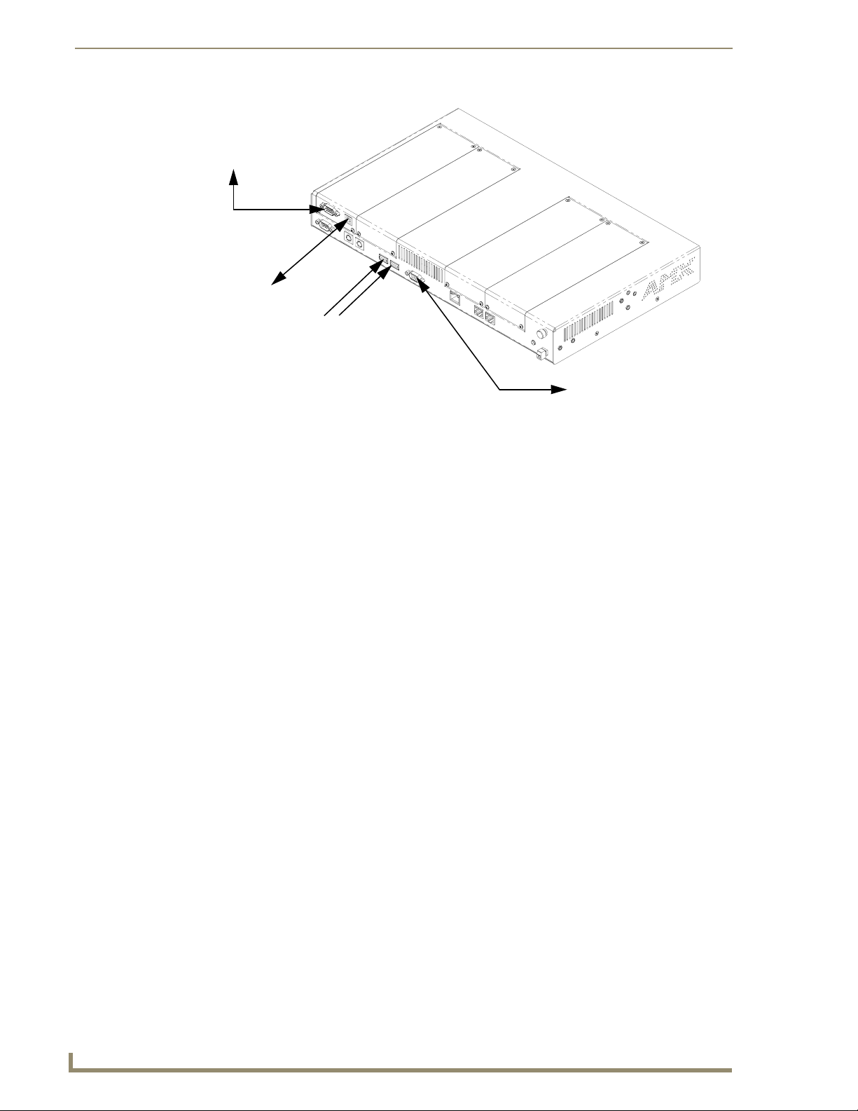
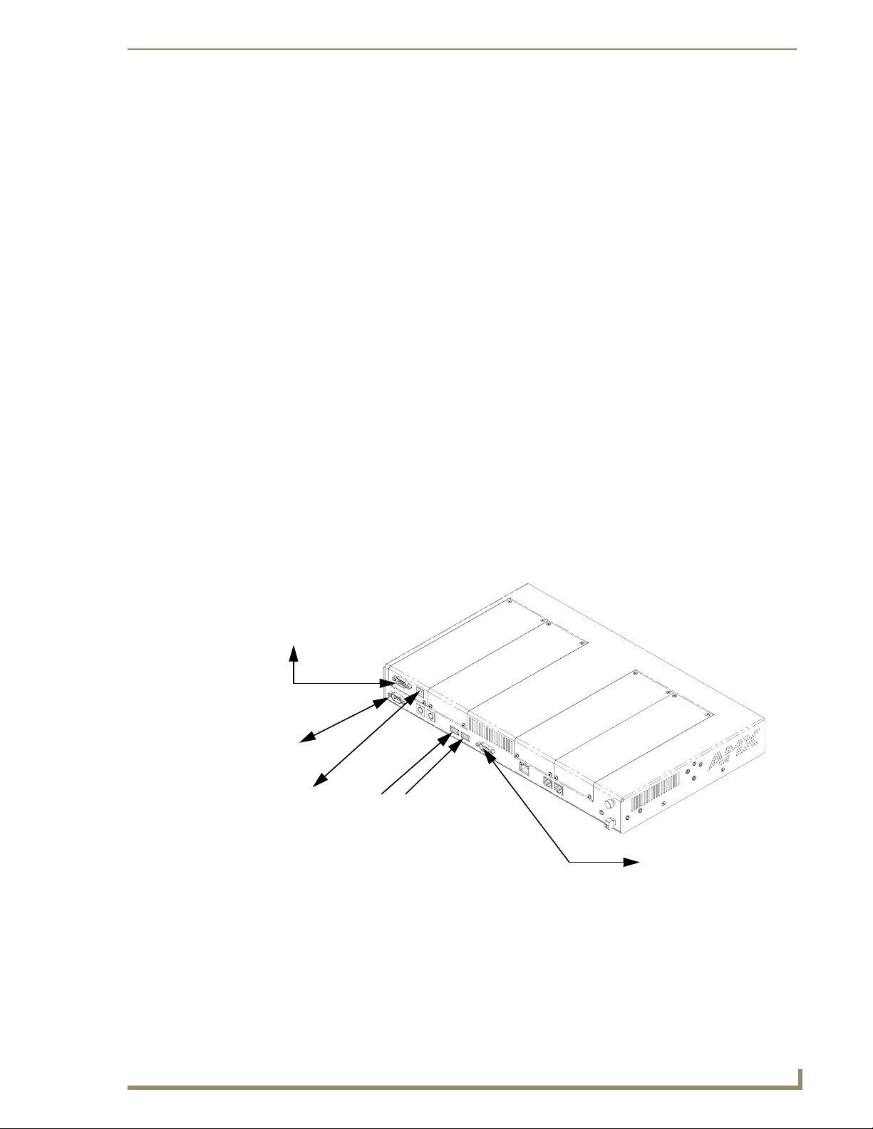
TPI/4 Front and Rear Components
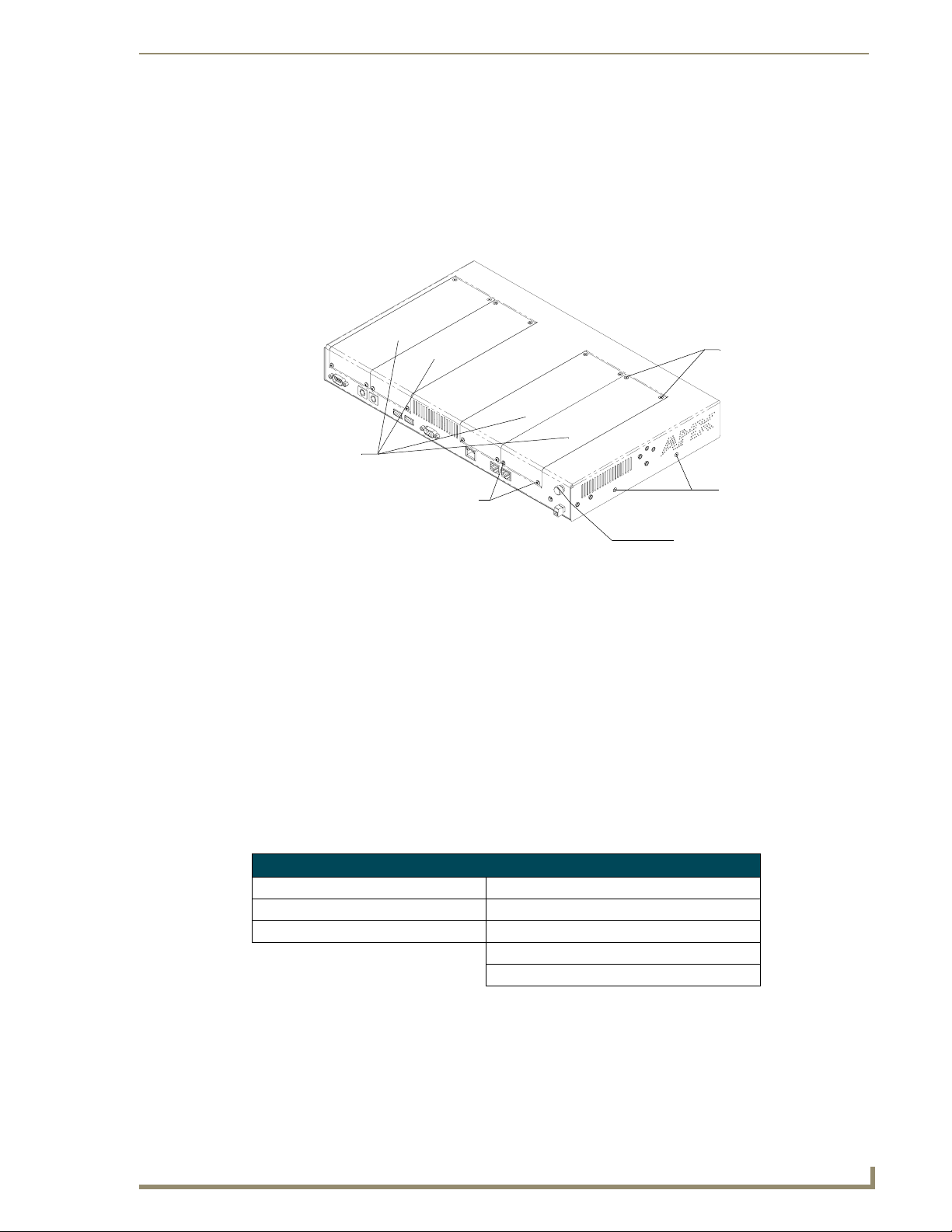
FIG. 3 shows the components on both the front and rear of the NXP-TPI/4.
Rack and under-table bracket locations
Product Information
PWR LED
DB9 SERIAL
port
Front View
Rear View
Input Slot 4
DB9 Touch
Input port
FIG. 3 NXP-TPI/4 (front and rear views)
ICSP LED
INPUT 1 LED
INPUT 2 LED
INPUT 3 LED
INPUT 4 LED
Input Slot 3
Keyboard PS/2 Connector port
Mouse PS/2 Connector port
HD-15 VGA
Output port
USB
Por ts ( 2)
RJ-45 10/100baseT
Ethernet Connector port
Input Slot 2
Audio
connector
Input Slot 1
SETUP button
CALIBRATE
button
TOUCH button
RESOLUTION
button
Grounding
bolt
12 VDC
PWR
connector
RJ-45 ICSNet
Connector
ports (2)
NXP-TPI/4 NetLinx Touch Panel Interface
7
Page 14

Product Information
Ethernet ports used by the TPI/4
Ethernet Ports Used by the TPI/4
Port type Description Standard Port #
ICSP Peer-to-peer protocol used for both Master-to-Master and Master-to-
device communications.
For maximum flexibility, the NetLinx Master can be configured to utilize a
different port than 1319, or disable ICSP over Ethernet completely from
either Telnet or the Program Port located on the NetLinx Master itself.
ICMP You must be able to PING an NetLinx Master to be able to connect to it
over a network.
TELNET There is a Telnet server that is used to configure and diagnose a NetLinx
system.
For maximum flexibility, the NetLinx Master can be configured to utilize a
different port than 23, or disable Telnet completely from either Telnet or the
Program Port located on the NetLinx Master itself. Once disabled, the only
way to enable Telnet again is from the NetLinx Master’s program port.
1319 (UDP/TCP)
ICMP
23 (TCP)
Connecting and Using USB Input Devices
This unit can have up to two USB-capable input devices connected for use both on its different firmware
and TPD4 panel pages. These input devices can consist of a keyboard or mouse.
USB-connected input devices are detected and recognized by the unit upon
connection.
1. Insert the input device USB connectors into the appropriate USB connector on the TPI/4.
2. Press the on-screen Reboot button from the Protected Setup page to save any changes and restart
the unit.
3. After the splash-screen disappears:
If a USB mouse has been connected, a mouse cursor appears on the screen and its location
corresponds to the mouse cursor position sent by the external USB mouse.
If a USB keyboard has been connected, only on-screen keyboards and keypads will reflect any
external keystrokes sent from the external USB keyboard.
8
NXP-TPI/4 NetLinx Touch Panel Interface
Page 15
Installation
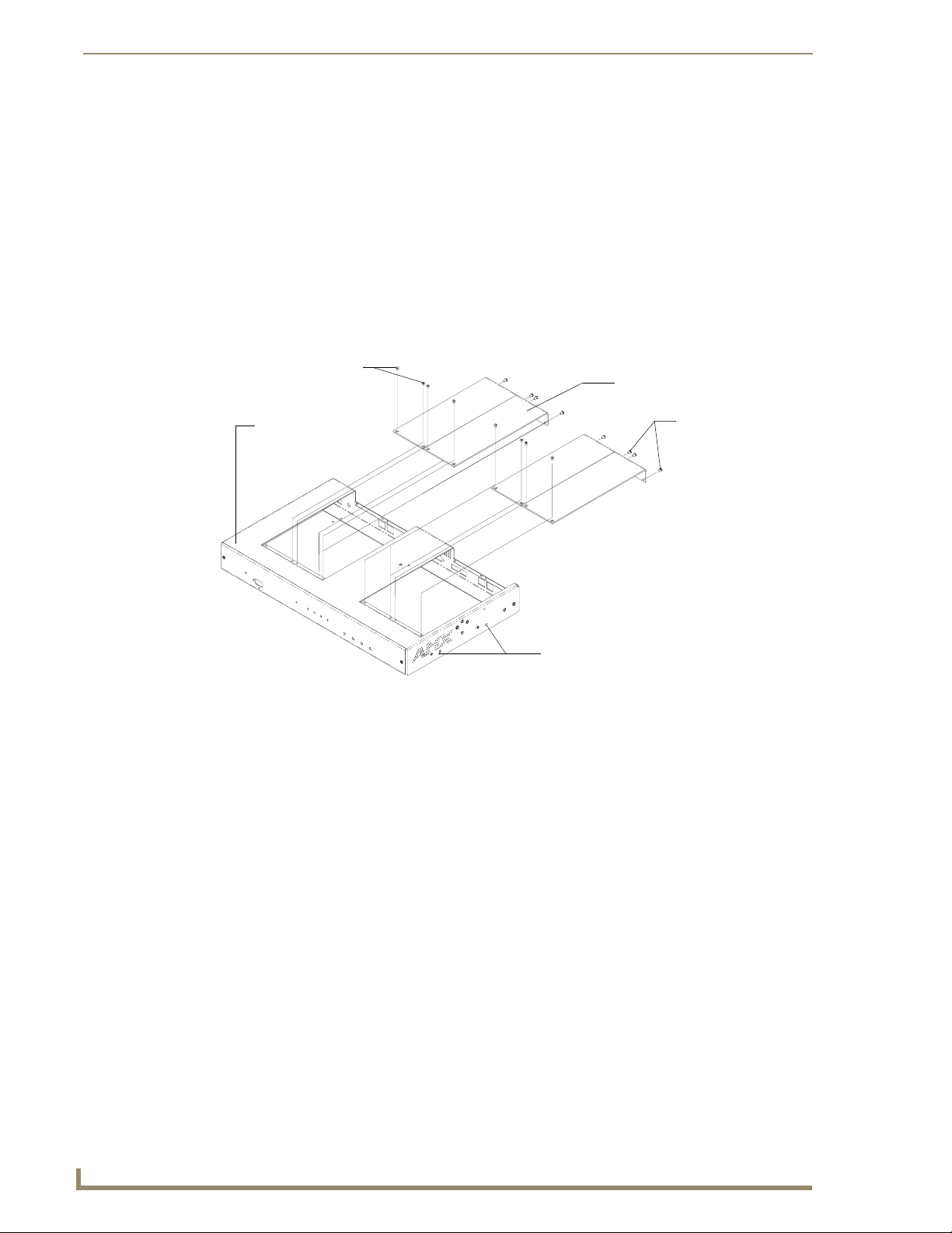
The NXP-TPI/4 is delivered from the factory with four installed input card covers (FIG. 4). The unit is
capable of supporting any combination of up to four TP4 input cards. The two different types of input
modules are the TP4-RGB and TP4-VID.
Input card covers
Installation
Flat-head screws
Round screws
FIG. 4 Factory default NXP-TPI/4
Housing screws
Grounding Bolt
Upgrading the Memory and Compact Flash
The TPI/4 unit is shipped with two default modules (an EXM memory module and a Compact Flash
card). Each module has a storage size of 64 MB.
These components are on the internal circuit board. ANY MEMORY UPGRADE
should be done after the removal of the factory installed card covers and
housing.
The best method of accessing the modules is to remove the outer TPI/4 housing,
replace the modules, then reinstall the housing. Refer to the Step 2: Removing the
Outer TPI/4 Housing section on page 10 for more details.
The Compact Flash card is factory programmed with specific TPI/4 firmware. These components can be
ordered from AMX in several different upgrade sizes (as listed in the following table):
Optional Module Upgrades
EXM Memory Module Compact Flash
NXA-EXM128M - 128 MB memory card NXA-CFTPI128M - 128 MB compact flash card
NXA-EXM256M - 256 MB memory card NXA-CFTPI256M - 256 MB compact flash card
NXA-CFTPI512M - 512 MB compact flash card
NXA-CFTPI1G - 1 GB compact flash card
Carefully remove the components from the shipping box. Refer to the Specifications table on page 2 for
more information on the unit and the available input cards.
NXP-TPI/4 NetLinx Touch Panel Interface
9
Page 16
Installation
Step 1: Removing Input Card Covers
Detach all connectors from the TPI/4 unit.
1.
Always power-down the unit before attempting to remove or install input modules.
Failure to do so could result in damage to the TPI/4 and input cards.
Do not to allow the card covers to fall through the housing and onto the circuit board
during the removal process.
2. Discharge any static electricity from your body by touching a grounded metal object or the
grounding bolt shown in FIG. 4.
3. Carefully remove each card by unscrewing both the two flat-head (top of each cover) and round
Phillips-head screws (rear of each cover) as shown in FIG. 5.
Flat-head screws
Outer housing
Housing screws
FIG. 5 Removing input card covers
Blank card covers
Round screws
4. Securely grasp the input card cover.
5. Remove the screws from the input card cover and repeat this removal process for each cover.
6. Once the screws are removed, pull the cards upwards and away from the main TPI/4 unit.
Step 2: Removing the Outer TPI/4 Housing
10
1.
Detach all connectors from the TPI/4 unit.
2. Verify the removal of all input card covers from the housing.
3. Carefully remove the housing by unscrewing the four flat Phillips-head screws from both sides of
the TPI/4 outer housing (2 per side as seen in FIG. 5 and FIG. 6) and the three flat
Phillips-head screws from along the rear-underside of the unit.
4. Unscrew the two connector bolts (four total) from either side of the rear TOUCH INPUT and VGA
OUTPUT connectors.
5. Carefully unscrew the grounding bolt from the rear of the TPI/4 unit.
6. Carefully remove the outer housing by gently sliding the top housing away from the front of the
unit. The removal allows you to view the internal memory located on the main board (FIG. 6).
NXP-TPI/4 NetLinx Touch Panel Interface
Page 17

Installation
Compact Flash card
Input card
connectors
Extended memory
module
FIG. 6 Location of the memory modules
Battery
EMI gasket
location
Housing screws
Step 3: Upgrading the internal EXM memory module
With the housing removed, locate the EXM memory module on the main board. Refer to FIG. 6 for
1.
location information.
2. Discharge any static electricity from your body by touching a grounded metal object or the
grounding bolt shown in FIG. 4 on page 9.
3. Firmly grip the metallic braces (located on each side of the memory module) and pull them both
outwards until the previous module pops-up.
Pull tabs outward
Connector
Alignment
groove
Metallic
braces
FIG. 7 Removing the memory module
Module flips upwards
Pull memory
out at a 45° angle
4. Firmly grasp the existing memory module and pull it out at a 45° angle away from the connector
location on the main board.
5. Remove the memory module upgrade from the anti-static bag.
6. Firmly grasp the new memory module (from the edges) and insert the pins (at a 45° angle) into the
opening on the connector.
NXP-TPI/4 NetLinx Touch Panel Interface
11
Page 18

Installation
Verify the new EXM memory module is correctly positioned using the alignment
groove located on the connector (as seen in FIG. 7 above).
7. While maintaining the 45° angle alignment on the new module, push it in firmly until the contact
pins are completely inside the connector.
8. Push the card downward (to the main board) until the metallic braces snap around the memory
module and hold it in place.
9. To complete the upgrade process, continue with the following step and/or re-install the outer
housing. Refer to the following sections for related procedures.
Step 4: Upgrading the internal Compact Flash card
1.
Discharge any static electricity from your body by touching a grounded metal object or the
grounding bolt shown in FIG. 4 on page 9.
2. With the housing removed, locate the 64 MB Compact Flash card on the main board (for location
information, see FIG. 6 on page 11).
3. Insert a grounded flat-head screwdriver into one of the card removal grooves (located on either side
of the card), and gently pry the card up and off the connector pins (FIG. 8). This alternating action
causes the card to "wiggle" away from the on-board connector pins.
Under-side indention
located below
On-board Compact
Flash connector
Insert with arrow
facing towards the pins
FIG. 8 Removing the Compact Flash card
4. Slip your finger into the opening between the connector pins and the card, and push the card out to
remove it.
5. Remove the upgrade card from its’ anti-static bag.
6. Insert the upgrade card into the connector opening with the arrow facing towards the pins, then push
it in firmly until the contact pins are completely inside the Compact Flash card and securely
attached to the connector.
7. Follow the procedures outlined in the following section to complete the upgrade process and
resecure the outer housing back onto the TPI/4.
12
NXP-TPI/4 NetLinx Touch Panel Interface
Page 19

Installation
Step 5: Re-Installing the TPI/4 Outer Housing
Slide this previously removed cover gently back towards the rear of the unit until the housing is
1.
flush with the rear connectors.
When installing the TPI/4 housing, verify the EMI gasket (FIG. 6 on page 11) remains
flush against the rear of the housing. This gasket (and its corresponding location) is
necessary to maintain FCC compliance.
2. Carefully install the housing by screwing-in the four flat Phillips-head screws into both sides of the
TPI/4 outer housing (2 per side as seen in FIG. 9) and the three flat Phillips-head screws into the
openings along the rear-underside of the unit.
3. Screw-in the two connector bolts (four total) to each side of both the TOUCH INPUT and VGA
OUTPUT connectors. DO NOT OVERTIGHTEN.
4. Carefully insert and screw-in the grounding bolt to the rear of the TPI/4 unit.
5. Reinstall any blank input card covers to their desired locations.
The internal circuit board must not be exposed. DO NOT LEAVE ANY OPEN GAPS IN THE
HOUSING.
Step 6: Re-Installing TP4 Input Cards
Always power down the unit before attempting to remove or install input modules.
Failure to do so could result in damage to the TPI/4 and input cards.
Do not to allow the input cards to fall through the housing and onto the circuit board
during the installation process.
Detach all connectors from the TPI/4 unit.
1.
2. Discharge any static electricity from your body by touching a grounded metal object or the
grounding bolt shown in FIG. 9.
3. If there are any input card covers present on the unit, follow the steps outlined in the Step 1:
Removing Input Card Covers section on page 10 to safely remove any pre-installed blank input card
covers, as shown below in FIG. 9.
4. Carefully remove the input cards from their static-free bag and note the location of the
accompanying four Phillips-head screws (used in securing the card to the housing).
5. Carefully align the male pins (on the card) and female (on the TPI/4 circuit board) connector.
6. Connect the input card by inserting the male pins vertically down onto the female input connectors
on the motherboard, as shown in FIG. 9.
NXP-TPI/4 NetLinx Touch Panel Interface
13
Page 20
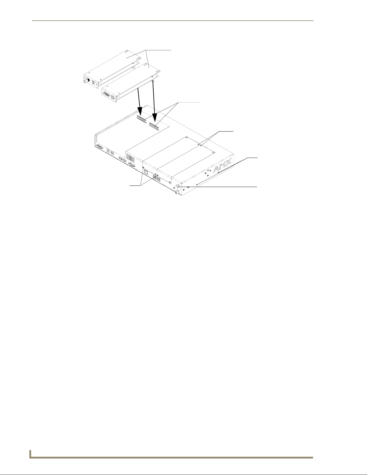
Installation
Input card
connectors (male)
TP4-VID
TP4-RGB
Motherboard
card
connectors (female)
Flat phillips-head screws
Housing screws
Round-head screws
FIG. 9 Inserting input modules
Grounding bolt
Be sure that each input card connector is attached to the corresponding set of pins
on the motherboard. FORCING A CONNECTION TO THE MOTHERBOARD CAN
DAMAGE OR BREAK CONNECTOR PINS and require the replacement of the entire
input card.
7. Gently push down on the input card (on the location above the pins) until it is securely connected to
the motherboard and fits into a card connector location.
8. Once secure, align the input card into the provided "slot" and verify that the TPD4 card holes
(2 on top and 2 at the rear) align with those located on the TPI/4 housing.
The flat Phillips-head screws must be used on top (flush against housing) and the
rounded Phillips-head screws must be used on the rear of the unit.
9. Repeat steps 2 through 8 to insert other input cards, if necessary.
It may be necessary to loosen and slightly move adjacent cards in order to maintain
the required "tight-seal" for both input cards. After the cards are adjusted to fit
together, tighten the connector screws to secure each cards’ location.
14
10. Screw-in (clockwise) the four screws (per card) to both the top and rear of the unit to secure each
card firmly to the TPI/4 (along the ends of the inserted input card) (FIG. 9).
NXP-TPI/4 NetLinx Touch Panel Interface
Page 21

Installation
Removing TP4 Input Cards
1. Detach all connectors from the TPI/4 unit.
Always power-down the unit before attempting to remove or install input cards.
Failure to do so could result in damage to the TPI/4 and/or input cards.
2. Discharge any static electricity from your body by touching a grounded metal object or the
grounding bolt shown in FIG. 9 on page 14.
3. Carefully unscrew the two flat Phillips-head (top of each card) and round Phillips-head screws
(adjacent to each card connectors, as shown in FIG. 9 on page 14.
4. Carefully insert a grounded flat-head screwdriver into the groove located at the top of the unit
(above the input connector location).
5. Apply a slight vertical pressure (push-up) to loosen the pins connected to the main board.
6. Gently pull-up (vertically from the TPI/4) on the input card using a slight rocking motion to loosen
the connector pin attachments.
7. Once the card is removed, cover the empty slot with an input card cover (FIG. 9 on page 14).
It may be necessary to loosen and slightly move adjacent cards in order to maintain
the required "tight-seal" for both input cards. After the cards are adjusted to fit
together, tighten the connector screws to secure each card location.
8. Screw-in (clockwise) the two rounded screws at the rear and two (2) flat screws on top of the unit to
secure each blank card cover firmly to the TPI/4.
9. Repeat steps 2 through 8 to remove other cards, as required.
10. Ensure that all screws are secured, reconnect all rear TPI/4 connectors, and apply power.
Before installing the TPI/4 unit into an equipment rack, confirm that ALL REAR
CONNECTORS ARE PROPERLY ATTACHED AND ALL INPUT CARDS ARE
SECURED. CONFIRM THERE IS ACTIVE ICSNET and ETHERNET
COMMUNICATION.
Wiring Guidelines for the NXP-TPI/4
The NXP-TPI/4 requires a 12 VDC-compliant power supply to provide power to the TPI/4 via the
2-pin 3.5 mm mini-Phoenix PWR connector.
The incoming PWR and GND wires from the power supply must be connected to the corresponding
locations within the PWR connector.
Do not connect power to the TPI/4 until wiring is complete. These units should only
have one source of incoming power. Using more than source of power to the panel
can result in damage to the internal components and a possible burn out.
Apply power to the panels only after installation is complete.
NXP-TPI/4 NetLinx Touch Panel Interface
15
Page 22
Installation
Grounding the TPI/4 Unit
Attach an earth-ground wire (typically from the equipment rack) to the grounding bolt located above the
PWR connector on the rear of the TPI/4.
Grounding the chassis ensures proper operation.
These units should only have one source of incoming power. Using more than one
source of power to the touch panel can result in damage to the internal components
and a possible burn out.
Apply power to the TPI/4 only after installation is complete.
Preparing captive wires
You will need a wire stripper and flat-blade screwdriver to prepare and connect the captive wires.
Never pre-tin wires for compression-type connections.
1. Strip 0.25 inch (6.35 mm) of insulation off all wires.
2. Insert each wire into the appropriate opening on the connector (according to the wiring diagrams
and connector types described in this section).
3. Tighten the screws to secure the wire in the connector. Do not tighten the screws excessively; doing
so may strip the threads and damage the connector.
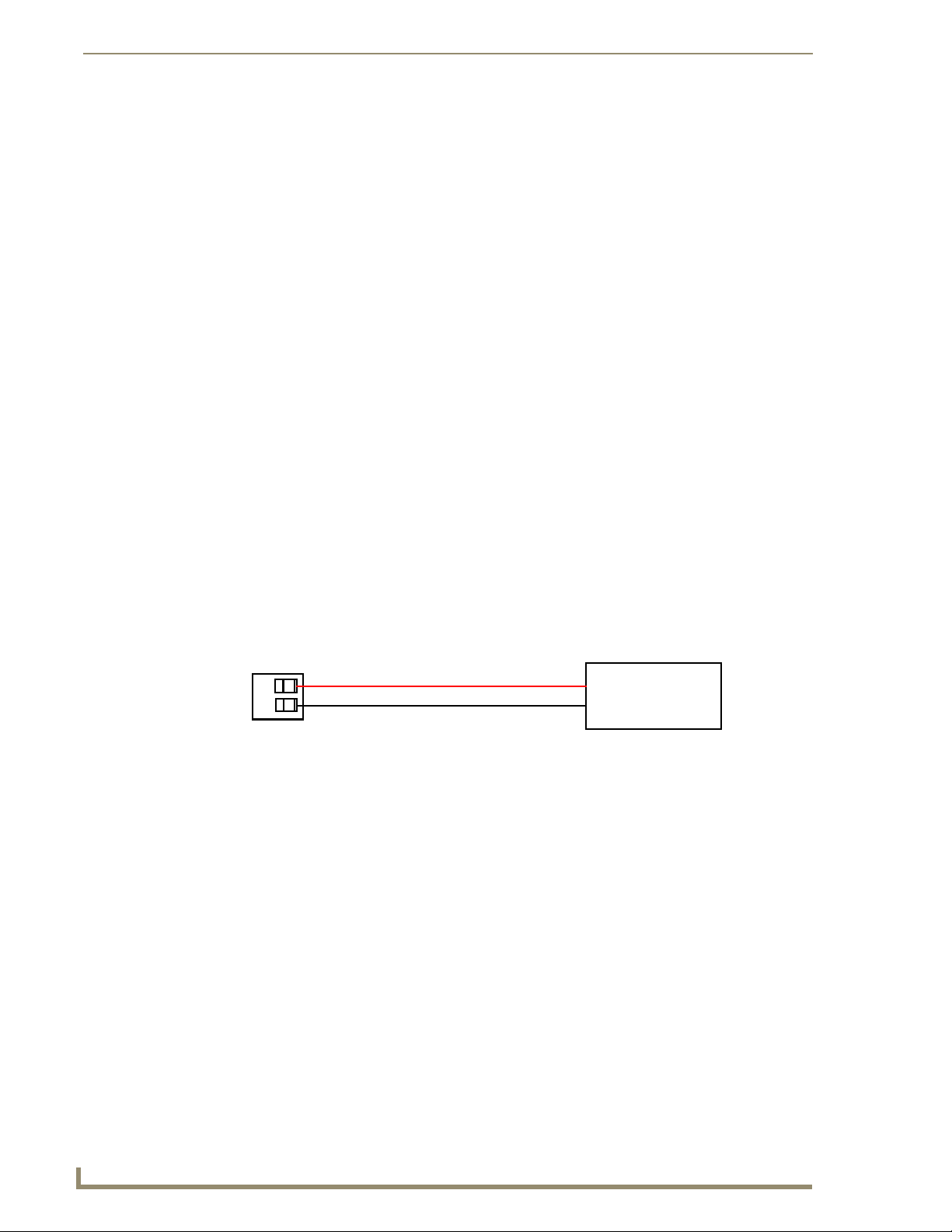
Wiring a power connection
To use the 2-pin 3.5 mm mini-Phoenix connector for use with a 12 VDC-compliant power supply, the
incoming PWR and GND wires from the external source must be connected to their corresponding
locations on the connector (FIG. 10).
PWR +
GND -
To the NXP-TPI/4
FIG. 10 NetLinx power connector wiring diagram
Power Supply
1. Insert the PWR and GND wires on the terminal end of the 2-pin 3.5 mm mini-Phoenix cable. Match
the wiring locations of the +/- on both the power supply and the terminal connector.
2. Tighten the clamp to secure the two wires. Do not tighten the screws excessively; doing so may strip
the threads and damage the connector.
3. Verify the connection of the 2-pin 3.5 mm mini-Phoenix to the external 12 VDC-compliant power
supply.
16
NXP-TPI/4 NetLinx Touch Panel Interface
Page 23
Installation
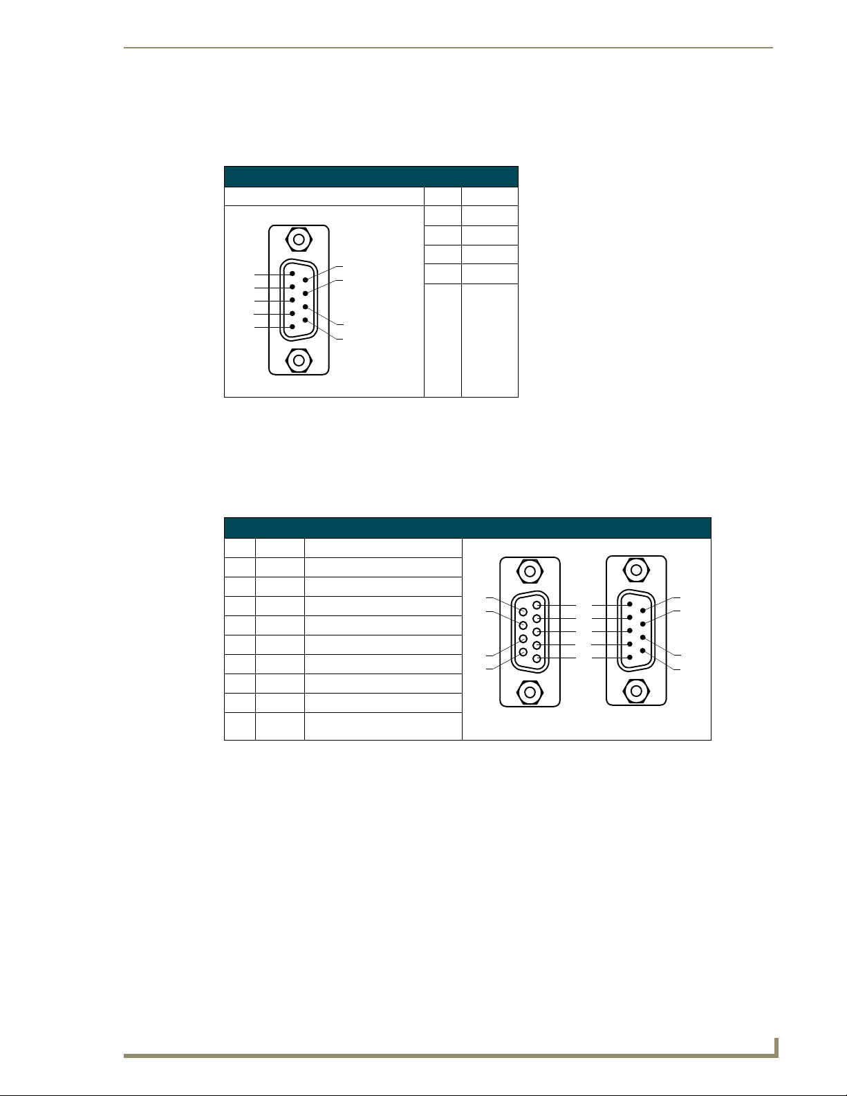
RS232 Serial Program Port: Connections and Wiring
The following table shows the front panel RS232 (DB9) Serial Program Port connector (male), pinouts,
and signals.
RS232 Program Port, Pinouts, and Signals
Program Port Connector Pin Signal
2RX
3TX
5GND
5
4
3
2
1
Male
9
8
7
6
7RTS
8CTS
DB9 Port: Connections and Wiring
Using a DB9 for Touch Input Connection and Panel Control
Attach the DB9 touch panel cable (male) to the 9-pin TOUCH INPUT connector (male) on the rear of
the TPI/4. The following table lists the (DB9) RS-232 connector pinouts.
(DB9) RS-232 Connector Pinouts
Pin Signal Function
1 N/A Not used
2 RXD Receive data
3 TXD Transmit data
4 DTR Data terminal ready
5 GND Signal ground
6 DSR Data set ready
7 RTS Request to send
8 CTS Clear to send
9 N/A Not used
9
8
7
6
Female
from touch device
5
4
3
2
1
Male
on TPI/4
9
8
7
6
Using a DB9 for Mouse Pass-Thru Control (Hardware Handshaking)
Hardware handshaking describes the interaction occurring between the TPI/4 and a PC which allows
mouse pass-thru control of the PC. This feature is enabled by using the ^TPS command on page 123 to
either enable or disable the pass-thru feature through the TPI/4 front Program port. Use a DB9 cable
(female) to DB9 NullModem (female) cable to connect the Program port on the TPI/4 to the rear RS-232
COM port on the PC. Another option is to use a Full NullModem (male/male) connector to bridge the
gap between to DB9 female connectors.
NXP-TPI/4 NetLinx Touch Panel Interface
17
Page 24
Installation
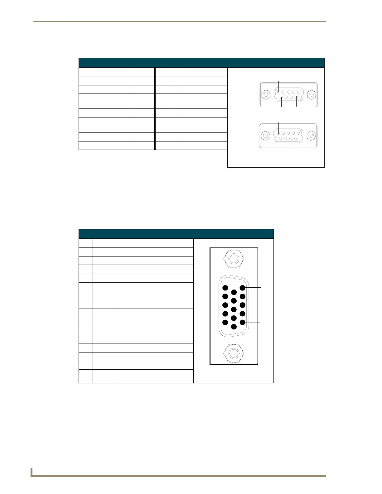
The following table lists the DB9 connector pinouts.
DB9 (female to female) Null Modem Pinouts
DB9 A Signal DB9 A DB9 B DB9 B Signal
Receive Data (RXD) 2 3 TXD
Transmit Data (TXD) 3 2 RXD
Data Terminal Ready
(DTR)
System Ground (GND) 5 5 GND
Data Set Ready (DSR)
+ Carrier Detect
Request to Send (RTS) 7 8 CTS
Clear to Send (CTS) 8 7 RTS
4 6 + 1 DSR + Carrier Detect
6 +1 4 DTR
DB9 female
connector
side A
DB9 female
connector
side B
51
96
51
9
6
VGA Port: Connections and Wiring
Using the VGA OUT HD-15 high-density connector
Connect the VGA source equipment HD-15 (male) connector (from the touch device) to the
VGA OUT HD-15 high-density connector (female) on the rear panel of the TPI/4. The following table
below lists the VGA OUT HD-15 connector pinouts.
VGA IN HD-15 Connector Pinouts
Pin Signal Function
1 Red Red signals
2 Green Green signals
3 Blue Blue signals
4 N/A Not used
5 GND Signal Ground
6 RAGND Red analog ground
7 GAGND Green analog ground
8 BAGND Blue analog ground
9 N/A Not used
10 SAGND Synchronization analog ground
11 N/A Not used
12 N/A Not used
13 HSYNC Horizontal synchronization signal
14 VSYNC Vertical synchronization signal
15 N/A Not used
5
1
VGA HD-15 (male)
connector
10
15
11
6
18
NXP-TPI/4 NetLinx Touch Panel Interface
Page 25
Installation
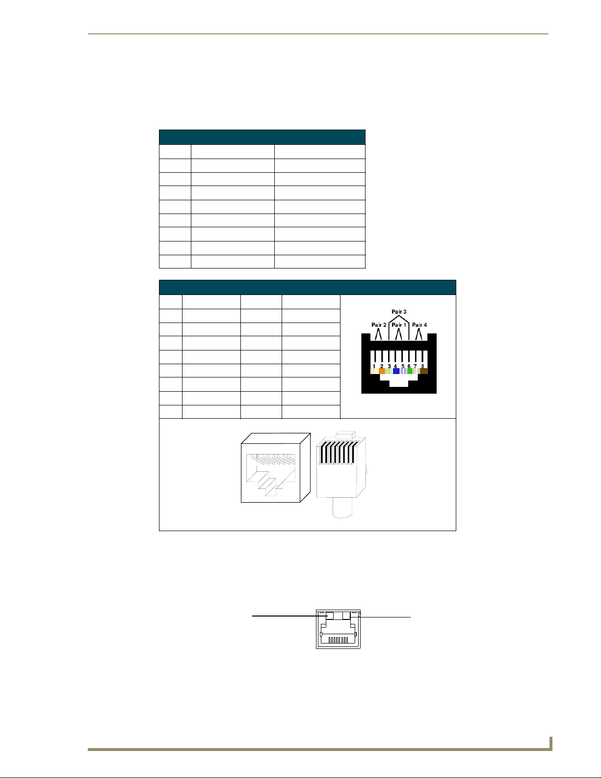
ICSNet Port: Connections and Wiring
The following tables show the signal and pinout/pairing information used for ICSNet RJ-45 data
connections. ICSNet uses a standard CAT5 Ethernet cable to provide communication between the
NXP-TPI/4 touch panel interface and the NetLinx Master.
ICSNet RJ-45 Signals
Pin Signal-Master Signal-TPI/4
1 TX + RX +
2 TX - RX -
3N/A N/A
4GND GND
5N/A N/A
6N/A N/A
7 RX + TX +
8 RX - TX -
RJ-45 Pinout Information (EIA/TIA 568 B)
Pin Wire Color Polarity Function
1 Orange/White + Transmit
2 Orange - Transmit
3 Green/White - Mic
4 Blue - Ground
5 White/Blue + 12 VDC
6 Green + Mic
7 White/Brown + Receive
8 Brown - Receive
TIA 568B
1 2 3 4 5 6 7 8
1 2 3 4 5 6 7 8
(female) (male)
RJ-45 connector - pin configurations
Ethernet/RJ-45 Port: Connections/Wiring
FIG. 11 describes the blink activity for the Ethernet 10/100 Base-T RJ-45 connector and cable. The
Ethernet cable is connected to the rear of the TPI/4.
A - Activity LED (yellow)
lights when receiving or
transmitting Ethernet
data packets
FIG. 11
Ethernet connector (showing communication and connection LEDs)
A L
ETHERNET
10/100
L - Link LED (green) lights when
the Ethernet cables are connected
and terminated correctly.
NXP-TPI/4 NetLinx Touch Panel Interface
19
Page 26

Installation
The following table lists the pinouts, signals, and pairing associated with the Ethernet connector.
Ethernet RJ-45 Pinouts and Signals
Pin Signals Connections Pairing Color
1 TX + 1 --------- 1 1 --------- 2 Orange-White
2 TX - 2 --------- 2 Orange
3 RX + 3 --------- 3 3 --------- 6 Green-White
4 no connection 4 --------- 4 Blue
5 no connection 5 --------- 5 4 --------- 5 Blue-White
6 RX - 6 --------- 6 Green
7 no connection 7 --------- 7 7 --------- 8 Brown-White
8 no connection 8 --------- 8 Brown
12 3 45 6 78
12 3 45 6 78
FIG. 12 diagrams the RJ-45 pinouts and signals for the Ethernet RJ-45 connector and cable.
FIG. 12
RJ-45 wiring diagram
Hooking-up the TPI/4 Rear Cable Connections
1. Discharge any acquired static electricity by touching a grounded metal object or by touching the
grounded bolt attached to the rear of TPI/4 unit.
2. Verify the connection of the touch input cables from the touch monitor into the Touch Input Port on
the rear of the unit. This cable sends the touch input coordinates from the touch panel to the TPI/4.
Instead of a touch input device (such as from a touch panel-ELO, Wacom, etc...)
being connected to the rear of the TPI/4 for touch input; a monitor can be connected
to the unit without providing touch input.
When a monitor (or other non-touch device) is connected, choose NullTouch
for the touch driver.
3. Verify the connection of the monitor HD-15 video cable from the touch monitor to the
HD-15 VGA Output Port on the rear of the TPI/4.
4. Verify the connection of related PS/2 and USB cables to the rear of the unit.
5. Connect the power cable to the touch monitor (or other monitor type).
6. Connect the terminal-end of the power cable into an outlet to power-up the touch device.
7. Connect either an RJ-45 10/100baseT Ethernet connector to the Ethernet port or an ICSNet
connector to the ICSNet port on the rear of the unit. Communication can be achieved through either
method although not through both at the same time.
20
NXP-TPI/4 NetLinx Touch Panel Interface
Page 27

Installation
8. Connect the terminal end of either the Ethernet (to an Ethernet Hub) or ICSNet (to the powered
NetLinx Master being used for communication) cables to their respective locations.
Communication to the TPI/4 is always done thru the NetLinx Master and never
directly to the TPI/4.
9. Connect the incoming PSN power connector to the 12 VDC power connector on the rear of the unit.
DO NOT CONNECT POWER UNTIL THE UNIT IS COMPLETELY INSTALLED.
Using the TP4-RGB card for Pass-Thru Control
To enable a touch response on a panel page being routed through a computer; a pass-thru enabling must
be done. Pass-thru control allows the TPI/4 to act as a control bridge between a computer and a monitor
(typically with no touch features such as a CRT computer monitor). The pass-thru is enabled on the
TP4-RGB card.
The two PS/2 and two USB connectors on the rear of the TPI/4 are used to provide signals from a
Keyboard and/or Mouse (you are no longer limited to one mouse and one keyboard. You can use
USB hubs and multiple mice/keyboards in any configuration). The Type-B USB connection on the
TP4-RGB card is used for communication between the TPI/4 and the computer.
Pass-thru must be enabled to control devices through the RGB card when using
control devices that are connected to either the PS/2 and USB connectors on the rear
of the TPI/4 unit.
Refer to the commands in the ^MPS section on page 122 for the Mouse Pass-thru
command enabling pass-thru on the RGB card.
Using a CRT (Non-Touch Panel) for Mouse Pass-Thru Control
Computer control can be done by routing the Mouse control through the TPI/4 and displaying the results
on a CRT or non-touch enabled panel. In this scenario, the TPI/4 is virtually nonexistent as is akin to
connecting the monitor and mouse directly to the rear of the computer.
The PS/2 or USB mouse must be connected before the initial power-up cycle. If
connected after the unit is powered, the TPI/4 must then have power cycled so that it
can detect the newly connected mouse. This detection is most useful when using a
CRT monitor.
The computer views the TPI/4 and RGB card combo as an adapter connected to a USB mouse device.
This method only allows for mouse control of the computer (as seen in FIG. 13).
1. Discharge any acquired static electricity by touching a grounded metal object or by touching the
grounded bolt attached to the rear of TPI/4 unit
2. Disconnect any incoming power connector from the rear of the TPI/4.
3. Connect either a PS/2 or USB mouse to the rear of the TPI/4 unit (as seen in FIG. 13).
NXP-TPI/4 NetLinx Touch Panel Interface
21
Page 28
Installation
Signal video feed
from the computer
to the monitor (RGB)
through the TPI/4
Type-B USB cable
between PC
and TPI/4
(control is on
panel pages
found on the
computer and
displayed on
non-touch monitor)
FIG. 13 Using the TP4-RGB card for mouse/keyboard pass-thru control
From USB Mouse
input device
(used to control
actions on computer
pages routed for viewing
through monitor)
Connect to CRT/monitor
VGA output
4. Connect a USB cable from a rear USB connector port (on the computer) to the Type-B USB host
port input connector on the TP4-RGB card
.
5. Connect a HD-15 cable from the rear video port (on the computer) to the VGA/RGB 15-pin male
HD-15 RGB input connector on the TP4-RGB card.
6. Connect the monitor’s HD-15 video cable to the VGA OUTPUT port on the rear of the TPI/4.
7. Cycle power to the unit. This cycling allows the unit to detect the new configuration.
8. Code a button on the touch panel page to enable the pass-thru feature on a selected input card slot.
Refer to the ^MPS section on page 122 for the specific command parameters to enable the Mouse
Pass-thru command on the RGB card. Toggling this coded panel button can
enable/disable the pass-thru feature.
22
The TPI/4 must first be set to match the resolution of the computers’ video output
resolution (page 28) and then must be adjusted to fit the available screen on the CRT
monitor. There could be a case where the image being generated from the
TPI/4 is slightly "off" and should be adjusted using the CRT’s on-board video
adjustment buttons.
9. Setup the TPI/4 output resolution using the procedures in the Step 1: Setting the Output Resolution
on the TPI/4 section on page 28.
If the TPI/4 is turned Off and then has power re-applied (power cycling), video
alignment settings done through the Video and/or RGB pages could be rest unless
the adjusted values have been previously saved. Refer to the Video Adjustment Video Adjustment section on page 63 for more information.
10. Use the CRT’s video adjust buttons to align the incoming video signal to fit into the available screen
area. Initially positioning the TPI/4 incoming video can reduce any later adjustments of the video
through the RGB Setup page (H-position, V-position, H-size, etc.).
NXP-TPI/4 NetLinx Touch Panel Interface
Page 29
Installation
Using a Touch Panel for both Mouse and Touch Pass-Thru Control
To enable a touch response on a panel page being routed through a computer; pass-thru enabling must
be done. Pass-thru control allows the TPI/4 to act as a control bridge between a computer and a touch
panel. The pass-thru is enabled on the TP4-RGB card.
This touch panel control option is available only if a Video Fill has been selected (select Yes from the
Windows >> Properties >> States TPD4 drop-down menu to enable). With Video Pass-Thru enabled,
the panel's touch coordinates are passed from the RGB card on a TPI/4 to the connected PC as USB
commands. This feature works only if the TP4-RGB card is connected directly to the PC, via the USB
port on the RGB card. The touch coordinates are scaled to fit the resulting window. This allows you to
"synch" the touch actions from the panel to those on the connected computer.
There is another way to allow touch pass-thru via the TPI4 RGB card instead of
issuing the ^MPS (Mouse pass-thru) and ^KPS (Keyboard pass-thru) send
commands.
The keyboard that is connected to the rear of the TPI/4 can assist in sending different
types of data by using the following keystrokes:
Ctrl+Alt+0 -> sends mouse and Keyboard data to TPI/4
Ctrl+Alt+1 -> sends mouse and Keyboard data to slot card 1
Ctrl+Alt+2 -> sends mouse and Keyboard data to slot card 2
Ctrl+Alt+3 -> sends mouse and Keyboard data to slot card 3
Ctrl+Alt+4 -> sends mouse and Keyboard data to slot card 4
Computer control can be done by routing the Mouse and touch panel input control through the
TPI/4. In this scenario, the TPI/4 is virtually nonexistent as is akin to connecting the touch panel and
mouse directly to the rear of the computer. The computer views the TPI/4 and RGB card combo as an
adapter connected to a USB mouse device. This method allows for both mouse and touch panel input
control of the computer (as seen in FIG. 14).
Signal video feed
from the computer
to the monitor (RGB)
through the TPI/4
Touch Input
from touch
panel
Type-B USB cable
between PC
and TPI/4
(control is on
panel pages
found on the
computer and
displayed on
touch panel)
FIG. 14 Using the TP4-RGB card for touch panel and mouse pass-thru control
From USB Mouse
input device
(used to control actions
on computer pages
being viewed on touch panel)
Connect to touch panel
VGA output
The PS/2 or USB mouse must be connected before the initial power-up cycle. If
connected after the unit is powered, the TPI/4 must then have power cycled so that it
can detect the newly connected mouse. This detection is most useful when using a
CRT monitor.
NXP-TPI/4 NetLinx Touch Panel Interface
23
Page 30

Installation
1. Discharge any acquired static electricity by touching a grounded metal object or by touching the
grounded bolt attached to the rear of TPI/4 unit.
2. Disconnect any incoming power connector from the rear of the TPI/4.
3. Connect either a PS/2 or USB mouse to the rear of the TPI/4 unit (as seen in FIG. 13).
4. Connect a USB cable from a rear USB connector port (on the computer) to the Type-B USB host
port input connector on the TP4-RGB card
.
5. Connect a HD-15 cable from the rear video port (on the computer) to the VGA/RGB 15-pin male
HD-15 RGB input connector on the TP4-RGB card.
6. Connect a DB9 touch input cable from the touch panel to the DB9 TOUCH INPUT connector on
the rear of the TPI/4 unit.
7. Connect the touch panels’ HD-15 video cable to the VGA OUTPUT port on the rear of the TPI/4.
8. Cycle power to the unit. This cycling allows the unit to detect the new configuration.
9. Code a button on the touch panel page to enable the pass-thru feature on a selected input card slot.
Refer to the ^MPS section on page 122 for the specific command parameters to enable the Mouse
Pass-thru command on the RGB card. Toggling this coded panel button can enable/disable the
pass-thru feature.
The TPI/4 must first be set to match the resolution of the touch panels’ video output
resolution (page 28), then select a Touch Driver (page 29). The video should
automatically fill-in the available screen area on the touch panel. There could be a
case where the image being generated from the TPI/4 is slightly "off" and should be
adjusted using the panel’s on-board video adjustment buttons.
10. Setup the TPI/4 output resolution using the procedures in the Step 1: Setting the Output Resolution
on the TPI/4 section on page 28.
If the TPI/4 is turned Off and then has power re-applied (power cycling), video
alignment settings done through the Video and/or RGB pages could be rest unless
the adjusted values have been previously saved. Refer to the Video Adjustment Video Adjustment section on page 63 for more information.
11. Setup the touch drivers for the connected touch panel by using the procedures in the Step 2: Setting
the Touch Drivers section on page 29.
12. If necessary, use the panel’s video adjust buttons to align the incoming video signal to fit into the
available screen area. Initially positioning the TPI/4 incoming video can reduce any later
adjustments of the video through the RGB Setup page (H-position, V-position, H-size, etc.).
24
NXP-TPI/4 NetLinx Touch Panel Interface
Page 31

Installation
Mounting the TPI/4 into an Equipment Rack
Use the supplied Rack Mounting Kit (includes the Rack Mount unit, attachment screws, bezel, and
magnetic faceplate) for 19" equipment rack installations. You will need a Phillips screwdriver to install
the TPI/4.
Before installing the TPI/4 unit into an equipment rack, confirm that ALL REAR
CONNECTORS ARE PROPERLY ATTACHED AND ALL INPUT CARDS ARE
SECURE. CONFIRM THERE IS ACTIVE ICSNET and ETHERNET
COMMUNICATION.
1. Discharge any static electricity from your body by touching a grounded metal object or the
grounding bolt shown in FIG. 15.
2. Position the mounting brackets (rack-ears), as shown in FIG. 15, and secure them to the chassis
using the four Phillips-head screws supplied with the unit. The mounting brackets (62-2275-07) can
be rotated to accommodate your mounting needs.
Grounding Bolt
Top v i e w
Faceplate
alignment
screw holes (2)
Rack Mount securing
holes (4 per side)
Front view
Screw attachment locations between
rack ears and equipment rack
FIG. 15 Installing the NXP-TPI/4 into an equipment rack
Side view
3. Connect any applicable wires to the NXP-TPI/4. Refer to the Hooking-up the TPI/4 Rear Cable
Connections section on page 20 for wiring diagrams and pinout descriptions.
4. Connect the terminal NetLinx wiring to the Central Controller, RS-232, Ethernet, ICSNet, USB,
and optional video/graphic wiring to the source equipment.
5. Carefully slide the entire Rack Mount - TPI/4 combo into an open slot in an equipment rack until
the screw attachment brackets lie flush against the equipment rack.
6. Secure the Rack Mount to the equipment rack by screwing in (clockwise) the four-#10-32 screws
and four-#10 washers supplied in the Assembly Kit.
7. Mount the Faceplate (MA2001-11) to the front of the unit by first inserting two Phillips-head screws
(included) into the front Faceplate alignment screw holes and then securing the it to the chassis.
NXP-TPI/4 NetLinx Touch Panel Interface
25
Page 32

Installation
8. The transparent plastic AMX cover can be removed to gain better access and visibility of the front
LEDs and pushbuttons.
Other Mounting Options
The TPI/4 comes included with rack ears that can be rotated 90° in any direction to accommodate several
different mounting options, including tabletop, under/over the table, and vertical wall mounting. Rotate
the mounting brackets to mount the NXP-TPI/4 on top of a flat surface, under-table, or vertically. The
following steps apply to all of these mounting options.
1. Discharge any static electricity from your body by touching a grounded metal object or the
grounding bolt shown in FIG. 15.
2. Disconnect the NetLinx connector from the Central Controller, the RS-232, Ethernet, USB, audio,
and optional video/graphic wiring from the source equipment.
3. Position and install the mounting brackets, as shown in FIG. 16, using the screws supplied with the
unit. The mounting brackets can be rotated to accommodate your mounting needs.
Mounting brackets (rack ears)
Four Phillips flat-head
screws
FIG. 16 Installing mounting brackets
4. Connect any applicable wires to the NXP-TPI/4.
Refer to theWiring Guidelines for the NXP-TPI/4 section on page 15 for wiring diagrams and pinout
descriptions.
5. Connect the terminal NetLinx wiring to the Central Controller, RS-232, Ethernet, ICSNet, USB,
and optional video/graphic wiring to the source equipment.
26
NXP-TPI/4 NetLinx Touch Panel Interface
Page 33

TPI/4 and Panel Interface Setup
The information contained within this section refers to the procedures necessary to setup the TPI/4
resolution, assign a touch driver, and calibrate that driver for use with a connected touch panel.
The PS/2 or USB mouse must be connected before the initial TPI/4 power-up.
If connected after the unit is powered, the TPI/4 must have power cycled so that it
can detect the newly connected mouse. This detection is most useful when using a
CRT monitor.
Verify you are using the latest NetLinx Master firmware.
Verify you are using the latest TPI/4 firmware (currently is using build 67 or higher.
The TP4 input cards are using the upgraded (version 2) card firmware.
Verify the NetLinx Studio program being used is Version 2.4 or higher.
Verify the TPDesign4 program being used is Version 2.6 or higher.
The TPI/4 has not been factory setup with specific touch panel pages. The first splash screen that appears
(FIG. 17) indicates the TPI/4 is receiving power, loading firmware, and preparing to display the default
touch panel page. When the panel is ready, the AMX Splash Screen is replaced by the Initial Panel Setup
page.
TPI/4 and Panel Interface Setup
AMX Splash Screen
(appears during power-up)
FIG. 17 Default AMX splash screen and Initial panel page
TPI/4 Startup Routine and Initial Panel Response
1. Discharge any acquired static electricity by touching a grounded metal object or by touching the
grounded bolt attached to the rear of TPI/4 unit.
2. Verify the rear connections are secure and active. Refer to the Hooking-up the TPI/4 Rear Cable
Connections section on page 20 for more detailed cable connector information.
3. Connect the terminal-end of the PSN into an outlet to begin powering-up the unit and initialize the
startup routine.
Upon start-up, the panel displays a default page that explains the functions of the four
buttons located on the front of the TPI/4 unit. These on-screen push-buttons
ARE NOT ACTIVE and are displayed only for descriptive purposes. Refer to the
following section for more detailed explanations on the use of the front panel buttons.
4. The initial panel page that appears on the LCD breaks-down the four steps necessary to properly
setup the TPI/4 and use it with either a touch panel or CRT monitor.
NXP-TPI/4 NetLinx Touch Panel Interface
Initial Panel Page
(General TPI/4 Setup procedures)
27
Page 34

TPI/4 and Panel Interface Setup
5. After the startup routine, the connected touch panel displays one of two possible screens:
If the resolution of the TPI/4 matches the supported resolution of the panel, continue by
If the TPI/4 output resolution does not match the resolution of the connected panel, an OUT
Step 1: Setting the Output Resolution on the TPI/4
To correct the problem of an OUT OF RANGE message, the TPI/4 output resolution must be set to
match the same output pixel resolution and refresh rate set on the connected panel/monitor.
The default TPI/4 output resolution is 640 x 480 @60Hz. Use the front panel RESOLUTION button to
alter the outgoing resolution (for a maximum of 1280 x 1024 @60 Hz).
1. Press and firmly hold-down the front panel RESOLUTION button. This single press opens the
Resolution Setup page (FIG. 18).
setting the touch drivers associated with the LCD (if any). Refer to the Step 2: Setting the
Touch Drivers section on page 29.
OF RANGE message appears, and you must use the following steps to adjust the output
resolution of the TPI/4 to match the panel.
This feature is monitor dependant and the range message is generated by the monitor (not by
the TPI/4). LCD monitors do not display a message but appear blank.
Previously saved output resolution
Currently selected output resolution
FIG. 18 Resolution Setup page (showing comparative resolutions)
Setting the resolution begins by displaying a comparison of the current/original output
resolution of the TPI/4 (on one line) and then displaying the first selectable display
resolution and refresh rate (on the next line). The selection process originates at a
640x480@60Hz display option and with every consecutive single push of the
RESOLUTION button, the TPI/4 resolution increases to a maximum output of
1280x1024@60Hz.
2. Firmly press the RESOLUTION button again to cycle through the available resolution settings.
Every consecutive button push cycles the output resolution to the next highest available setting. A
double-push of the RESOLUTION button adjusts the resolution to previous setting. The
following list describes the available pixel display and refresh rates.
• 640 x 480 @60Hz (default) • 800 x 600 @72Hz • 1024 x 768 @75Hz
• 640 x 480 @72Hz • 800 x 600 @75Hz • 1280 x 1024 @60Hz (highest setting)
• 640 x 480 @75Hz • 1024 x 768 @60Hz
• 800 x 600 @60Hz • 1024 x 768 @70Hz
28
NXP-TPI/4 NetLinx Touch Panel Interface
Page 35

TPI/4 and Panel Interface Setup
If your panel doesn’t match the initial TPI/4 output resolution, these manual setting
procedures must be done to "sync-up" both device settings.
Once your resolution is selected, you can use the outer screen area lines on the
Resolution Setup page to adjust your CRT monitor’s visible screen area. This could
involve using the monitor’s video control to stretch and move the incoming video so
that the borders follow the edges of the screen without disappearing. There are
normally 60 seconds before the resolution times-out, but you can press the front
panel Resolution button to continue.
3. After choosing the desired resolution, use the monitor’s video controls to stretch and move the
incoming video so the borders of the desired resolution pattern follow the edges of the screen
without disappearing. There is normally 60 seconds before the resolution times-out, but you can
press the front panel RESOLUTION button again to return to the previous resolution pattern and
continue setting-up the monitor.
4. Press and hold-down firmly the RESOLUTION button to save the resolution setting.
A message stating: "Please wait, loading new resolution..." appears to indicate the new resolution
being is saved. The Resolution Setup page then displays and exits the resolution setup process.
There is then some shifting of the defaulted Main page (which was developed for a 640 x 480
resolution).
5. Press the front panel TOUCH button to proceed with setting the Touch Drivers (next section).
Setting the touch drivers is mostly used when connected the TPI/4 to a touch panel.
If using a CRT, set the touch drivers to NullTouch.
Step 2: Setting the Touch Drivers
After matching the resolution between the TPI/4 and panel/monitor, the next step is to select the
necessary touch drivers from the available series provide through the TPI/4.
1. Press the TOUCH button on the front panel of the TPI/4 to set the touch driver and open the on-
screen Protected Setup page (FIG. 19). The default Touch Input Driver is EloTouch
Select NullTouch when using a CRT
or other non-touch monitor
®
.
FIG. 19 Protected Setup page
2. Press the front panel TOUCH button to cycle through the series of available touch input drivers
(firmware build 67 or higher) shown in the following list:
Verify that the selected touch driver matches the connected touch panel or monitor.
NXP-TPI/4 NetLinx Touch Panel Interface
29
Page 36

TPI/4 and Panel Interface Setup
NXP-TPI/4 Touch Input Drivers
Driver: Description:
AMXDL15A Selected when using an AMX DL15A touch panel.
®
Cirque
DynaPro
EloTouch
Elo19Touch
Eyegonomic
EZScreen
EZScreenV6
ISTTouch
Magnus Selected when using either a Magnus touch panel or other
MicroTouch
MicroTouchMT3000
MicroTouchPen
NullTouch
SanyoTouch
SerialMouse Selected when using a Microsoft
SmartTech
SyncMaster173v
®
Wacom
Wacom2
Selected when using a Cirque touch panel or other compatible
touch device driver.
®
Selected when using either a DynaPro touch panel or other
compatible DynaPro touch device driver.
®
Selected when using either an ELO® touch panel or other
compatible ELO touch device driver (default).
®
Selected when using a 19-inch ELO touch panel or other
compatible ELO touch device driver.
®
Selected when using either an Eyegonomic touch panel or other
compatible Eyegonomic touch device driver.
®
Selected when using either an EZScreen touch panel or other
compatible EZScreen touch device driver.
®
Selected when using either an EZScreenV6 touch panel or other
compatible EZScreen touch device driver.
®
Selected when using either an ISTTouch touch panel or other
compatible IST touch device driver.
compatible Magnus device driver.
®
Selected when using either a MicroTouch touch panel or other
compatible MicroTouch device driver.
®
Selected when using either a MicroTouchMT3000 model touch
panel or other compatible MicroTouch device driver.
®
Selected when using either a MicroTouchPen® touch device or
other serial SMT3(R)/TouchPen4(+) driver.
®
Selected when no touch driver is being used.
Use this option when working with a CRT monitor.
®
®
Selected when using either a SanyoTouch touch panel or other
compatible Sanyo
®
touch device driver.
®
compatible serial mouse.
Selected when using either a SmartTech touch panel or other
compatible SmartTech touch device driver.
®
Selected when using either a SyncMaster173v® touch panel or
other compatible SyncMaster device driver.
Selected when using either a Wacom® touch panel or other
compatible Wacom touch device driver.
®
Selected when using a Wacom® touch panel which requires the
use of additionally compatible Wacom touch device drivers.
30
3. Press the on-screen Reboot button to save your changes and reboot the connected TPI/4.
Refer to the List of Touch Monitors tested with the TPI4 section on page 139 for a comprehensive list of
Touch Monitors that have been tested with the TPI4.
NXP-TPI/4 NetLinx Touch Panel Interface
Page 37

TPI/4 and Panel Interface Setup
Step 3: Calibrating the TPI/4
1. Firmly press the front panel CALIBRATE button on the TPI/4. This process opens a calibration
page that uses a series of crosshair coordinate intersections to calibrate the touch panel (using the
newly selected touch driver).
If the wrong touch driver is selected prior to the calibration process, press any
front-panel button to exit the calibration process and re-select another touch driver.
If using a CRT monitor, DO NOT PRESS THE CALIBRATE BUTTON. Refer to the
Step 1: Setting the Output Resolution on the TPI/4 section on page 28 for detailed
CRT screen adjustment procedures.
2. If the calibration fails, return to the Protected Setup page and select another touch input driver.
3. Press the crosshairs (on the Calibration page) to set the calibration points on the LCD. A mouse
press can be used to simulate a touch on a panel.
4. After the "Calibration Successful." message appears, press anywhere to return to the Setup page.
It is recommended that you calibrate the TPI/4 before its initial use, after completing a
firmware download, and after switching touch input drivers (and touch devices).
5. Press the Protected Setup button (located on the lower-left of the panel page) to open the Protected
Setup page.
6. Enter 1988 into the Keypad’s password field and press Done when finished.
7. Press the on-screen Reboot button to cycle power to the TPI/4 and incorporate the new settings. The
touch monitor goes blank for a few seconds during the reboot process. You can also use a mouse to
press the on-screen Reboot button.
8. Upon start-up, press anywhere on the screen to return to the Protected Setup page and begin
defining the communication properties.
Step 4: Accessing the Firmware Setup Pages
1. Press the front panel SETUP button to open the Setup page.
2. Follow the procedures in the Configuring Communication section on page 33 to configure the
communication parameters for the NXP-TPI/4.
NXP-TPI/4 NetLinx Touch Panel Interface
31
Page 38

TPI/4 and Panel Interface Setup
32
NXP-TPI/4 NetLinx Touch Panel Interface
Page 39

Configuring Communication
Communication between the TPI/4 and the NetLinx Master consists of using either ETHERNET
(DHCP, Static IP) or ICSNet.
If you are currently using a static IP Address, continue with the IP Settings section Configuring a Static IP Address over Ethernet section on page 36.
Before commencing, verify you are using the latest NetLinx Master firmware.
Verify the NetLinx Studio program being used is version 2.x or higher.
Setting up the TPI/4 Device Number
1. Press the front panel SETUP button to open the Setup page.
Configuring Communication
Connection Status
Red Connection Status icon -
indicates no connection to
a Master
Green Connection Status icon -
indicates active
communication to a Master
FIG. 20 Setup page
2. Press the Protected Setup button (located on the lower-left of the page) to open the Protected Setup
page and display an on-screen keypad.
3. Enter 1988 into the Keypad’s password field and press Done when finished.
Clearing Password #5, from the initial Password Setup page, removes the need for
you to enter the default password before accessing the Protected Setup page.
4. Press the red Device Number field to open the Device Number keypad (FIG. 21).
5. Enter a Device Number value for the panel into the Device Number Keypad.
The default value is 2275 and the range is from 1 - 32000.
When using multiple TPI/4s within a NetLinx System, remember to assign unique
Device Number values to each panel so that all assigned panels appear in the
System listing for the target Master.
NXP-TPI/4 NetLinx Touch Panel Interface
33
Page 40
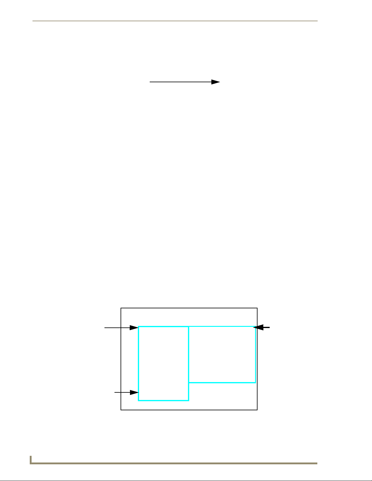
Configuring Communication
6. Press Done to close the keypad, assign the number, and return to the Protected Setup page.
FIG. 21 Protected Setup page with Keypad
7. Use the Baud Rate Up/Down arrows to cycle through the available Baud Rates for TPI/4 Serial
communication to the Master (according to the SW1 DIP switch configuration within the NetLinx
device). The default is 38400.
8. Press the on-screen Reboot button to restart the TPI/4 and incorporate any changes.
Before continuing, open NetLinx Studio. This program assists in developing a System
Number, Master IP/URL, and Master Port number. Refer to your NetLinx Master’s
instruction manual for more information.
9. Obtain the System Number and Master IP Address from NetLinx Studio. This information must be
specific for the system used with the configured TPI/4.
10. If you are not already in the Protected Setup page, either press the front panel TOUCH button or
from the Setup page press the Protected Setup button to return to the Protected Setup page.
11. Press the System Connection button (located on the Protected Setup page) to open the System
Connection page (FIG. 22) and begin configuring the communication settings on the TPI/4 to match
those of the target Master.
TPI/4
connection
information
MAC Address
from unit is
factory set to a
unique address
NetLinx Master’s
connection
information
34
FIG. 22 System Connection page
NXP-TPI/4 NetLinx Touch Panel Interface
Page 41

Configuring Communication
Master Connection - Using ICSNet
This method depends on first connecting the ICSNet cable, having the TPI/4
recognize it, and then setting up ICSNet communication.
Before beginning:
1. Ver i fy th a t a n ICSNet cable is connected from both the rear of the TPI/4 to the NetLinx Master and
from the Master to an ICSNet port.
2. Verify that the NetLinx Master is receiving power and is turned On.
If the TPI/4 was not already powered, continue with steps 3 and 4. These steps allow
the TPI/4 to cycle through its available ports and detect any attached connectors.
3. Connect the terminal end of the PSN power cable to the 12 VDC power connector on the rear of the
TPI/4 and supply power.
4. After the TPI/4 powers-up, press the SETUP button on the front of the TPI/4 unit to continue with
the setup process and proceed to the Setup page.
5. Press the Protected Setup > System Connection button (located on the lower-left) to open the
System Connection page (FIG. 23).
6. Toggle the ICSNET/Ethernet field (from the Master Connection section) until the choice cycles to
ICSNet. Refer to the System Connection Page section on page 75 for more information about the
fields on this page.
FIG. 23 System Connection page (using ICSNet)
ALL grey fields are read-only but still display the network information. Blue fields
toggle through available options. Red fields open the on-screen keyboard for
information editing.
7. Do not alter any of the fields in the IP Settings section (using DHCP as the default). These fields are
not user-editable and are used when connecting via ICSNet between the Master and the TPI/4.
8. Press the Protected Setup button on the touch panel to return to the Protected Setup page.
9. Press the on-screen Reboot button from the Protected Setup page to both save any changes and
restart the TPI/4.
NXP-TPI/4 NetLinx Touch Panel Interface
35
Page 42

Configuring Communication
After connecting the TPI/4 to the Master using ICSNet, NetLinx Studio’s Workspace
window shows both the Master and TPI/4 information in its’ System tree.
Configuring a Wired Ethernet Connection
It is necessary to tell the panel which Master it should be communicating with. This "pointing to a
Master" is done via the System Connection page where you configure the IP Address, System Number
and Username/Password information assigned to the target Master. Until those parameters are
configured, your Connection Status icon will remain red (indicating there is no current connection to a
Master).
Step 1: Configuring the Panel’s IP Settings
You can only configure the connection parameters for the TPI/4 through the System Connection page.
This type of communication can be established either via either a Dynamic IP Address (DHCP) or via a
pre-reserved Static IP Address (typically provided by your System Administrator).
IP Settings section - Configuring a DHCP Address over Ethernet
1.
Select Protected Setup > System Connection (located on the lower-left) to open the System
Connection page.
2. Locate the IP Settings section of this page.
3. Toggle the DHCP/Static field (from the IP Settings section) until the choice cycles to DHCP.
DHCP will register the unique MAC Address (factory assigned) on the TPI/4 and
once the communication setup process is complete, reserve an IP Address, Subnet
Mask, and Gateway values from the DHCP Server.
4. Press the optional Host Name field to open a Keyboard and enter the Host Name information.
5. Press Done after you are finished assigning the alpha-numeric string of the host name.
6. Do not alter any of the remaining greyed-out fields in the IP Settings section. Once the TPI/4 is
rebooted, these values are obtained by the unit and displayed in the DNS fields after power-up.
The information can be found in either the: Workspace- System name > Define
Device section of your code (that defines the properties for your panel), or in the
Device Addressing/Network Addresses in the Tools > NetLinx Diagnostics dialog.
7. Press the Back button to return to the Protected Setup page.
8. Press the on-screen Reboot button to both save any changes and restart the TPI/4.
IP Settings section - Configuring a Static IP Address over Ethernet
1.
Select Protected Setup > System Connection (located on the lower-left) to open the System
Connection page.
2. Locate the IP Settings section of this page.
Check with your System Administrator for a pre-reserved Static IP Address assigned
to the TPI/4. This address must be obtained before Static assignment of the TPI/4
continues.
36
3. Toggle the DHCP/Static field (from the IP Settings section) until the choice cycles to Static.
NXP-TPI/4 NetLinx Touch Panel Interface
Page 43

Configuring Communication
4. Press the IP Address field to open a Keyboard and enter the Static IP Address (provided by your
System Administrator).
5. Press Done after you are finished entering the IP information.
6. Repeat the same process for the Subnet Mask and Gateway fields.
7. Press the optional Host Name field to open the Keyboard and enter the Host Name information.
8. Press Done after you are finished assigning the alpha-numeric string of the host name.
9. Press the Primary DNS field to open a Keyboard, enter the Primary DNS Address (provided by your
System Administrator) and press Done when compete. Repeat this process for the Secondary DNS
field.
10. Press the Domain field to open a Keyboard, enter the resolvable domain Address (this is provided by
your System Administrator and equates to a unique Internet name for the TPI/4), and press Done
when complete.
11. Navigate to the Master Connection section of this page to begin configuring the communication
parameters for the target Master.
Step 2: Choosing a Master Connection Mode Setting
There are three Ethernet MODE settings used in the Master Connection section of the System
Connection page. URL is the most common method.
Master Connection MODE options:
• URL (Uniform Resource Locator) is the address that defines the route to a file on the Web or
any other Internet facility.
In this system, the panel acts as a "Client" and the Master acts as a Server (in that Clients attach
to it).
• LISTEN sets the TPI/4 to "listen" for broadcasts from the Master (using the panel IP from its URL
list). In this system, the TPI/4 acts as a "Server" (in that Clients attach to it) and the Master acts as
a "Client".
• AUTO is used to instruct the TPI/4 to search for a Master that uses the same System Number
(assigned within the Master Connection section) and resides on the same Subnet as itself. In this
case, the Master has its UDP feature enabled.
This UDP (User Datagram Protocol) is a protocol within the TCP/IP protocol suite that is used in
place of TCP when a reliable delivery is not required.
This UDP enabling is done through a Telnet session on the Master. Refer to the particular NetLinx
Master manual for more detailed information.
Step 3: Configuring the Ethernet Connection Type
When using Ethernet as your communication method, the NetLinx Master must first
be setup with either a Static IP or DHCP Address obtained from either NetLinx Studio
or your System Administrator.
Before beginning:
1. Verify the TPI/4 has been configured to communicate through an Ethernet cable connected from the
rear of the TPI/4 to a valid Ethernet Hub.
Before commencing, verify you are using the latest NetLinx Master firmware.
NXP-TPI/4 NetLinx Touch Panel Interface
37
Page 44

Configuring Communication
2. Verify that the NetLinx Master is receiving power and is communicating via an Ethernet connection
with the PC running NetLinx Studio.
3. Connect the terminal end of the PSN power cable to the 12 VDC power connector on the
rear of the TPI/4 unit.
If the TPI/4 was not already powered, continue with steps 4 - 7. These steps allow the
panel to cycle through its available ports and detect any attached connectors.
4. Connect the terminal end of the PSN power cable to the 12 VDC power connector on the rear of the
TPI/4.
5. Verify the green Ethernet LED (from the rear Ethernet port on both the Master and TPI/4) are
illuminated (indicating a proper connection).
6. Verify the green Ethernet LED (from the rear Ethernet port on the Master) is illuminated (indicating
a proper connection).
7. Verify the yellow LED (from the rear Ethernet port on the Master) is blinking (indicating
communication).
8. After the TPI/4 powers-up, press the front panel SETUP button to continue with the setup process
by proceeding to the Setup page.
9. Select Protected Setup > System Connection (located on the lower-left) to open the System
Connection page (FIG. 24).
Obtained
from
NetLinx
Master
FIG. 24 System Connection page
Master Connection - Virtual Master communication over Ethernet
When configuring your panel to communicate with a Virtual Master (on your PC), the
Master IP/URL field must be configured to match the IP Address of the PC and use
the Virtual System value assigned to the Virtual Master within NetLinx Studio.
Before beginning:
1. Verify the TPI/4 has been configured to communicate through an Ethernet cable connected from the
TPI/4 to a valid Ethernet Hub.
2. Launch NetLinx Studio 2 (default location is Start > Programs > AMX Control Disc > NetLinx
Studio 2 > NetLinx Studio 2).
38
NXP-TPI/4 NetLinx Touch Panel Interface
Page 45

Configuring Communication
3. Select Settings > Master Communication Settings, from the Main menu to open the Master
Communication Settings dialog (FIG. 25).
Enter this IP
into the
Master IP/URL
System Connection
FIG. 25 Assigning Communication Settings and TCP/IP Settings for a Virtual Master
field on the
page
IP Addresses of computer
(also obtained by using the
Start > Run > cmd command)
4. Click the Communications Settings button to open the Communications Settings dialog.
5. Click on the NetLinx Master radio button (from the Platform Selection section) to indicate that you
are working as a NetLinx Master.
6. Click on the Virtual Master radio box (from the Transport Connection Option section) to indicate
you are wanting to configure the PC to communicate directly with a TPI/4. Everything else such as
the Authentication is greyed-out because you are not going through the Master’s UI.
7. Click the Edit Settings button (on the Communications Settings dialog) to open the Virtual NetLinx
Master Settings dialog (FIG. 25).
8. From within this dialog enter the System number (default is 1) and note the IP Address of the target
PC being used as the Virtual Master. This IP Address can also be obtained by following these
procedures:
On your PC, click Start > Run to open the Run dialog.
Enter cmd into the Open field and click OK to open the command DOS prompt.
From the C:\> command line, enter ipconfig to display the IP Address of the PC. This
information is entered into the Master IP/URL field on the TPI/4.
9. Click OK three times to close the open dialogs, save your settings, and return to the main NetLinx
Studio application.
10. Click the OnLine Tree tab in the Workspace window to view the devices on the Virtual System.
The default System value is one.
11. Right-click on the Empty Device Tree/System entry and select Refresh System to re-populate the
list.
12. Connect the terminal end of the PSN power cable to the 12 VDC power connector on the rear of the
TPI/4.
13. After the TPI/4 powers-up, press and hold the front panel SETUP button to bring up the Protected
Setup page and continue with the setup process and proceed to the Setup page.
14. Select Protected Setup > System Connection (located on the lower-left) to open the System
Connection page (FIG. 26).
NXP-TPI/4 NetLinx Touch Panel Interface
39
Page 46

Configuring Communication
FIG. 26 Sample System Connection page (for Virtual Master communication)
15. Press the blue ICSNET/Ethernet field (from the Master Connection section) until the choice cycles
to the word Ethernet.
16. Press the Mode field until the choice cycles to the word URL.
17. Press the Master IP/URL field to open a Keyboard and enter the IP Address of the PC used as the
Virtual Master.
18. Click Done to accept the new value and return to the System Connection page.
19. Do not alter the Master Port Number value (this is the default value used by NetLinx).
20. Press the Back button to open the Protected Setup page.
21. Press the on-screen Reboot button to both save any changes and restart the TPI/4.
The System Number is
assigned to the Virtual
Master within the AMX
software application
(these must match)
Enter the IP Address
information of the PC
used as a Virtual
Master
By selecting URL, the System Number field becomes read-only (grey) because the TPI/4
pulls this value directly from the communicating target Master (virtual or not). A virtual
Master system value can be set within the active AMX software applications such as: NetLinx
Studio, TPD4, or IREdit.
Master Connection section - NetLinx Master Ethernet IP Address - URL Mode
In this mode, enter the System Number (zero for an unknown System Number) and the IP/URL of the
Master (Master Port Number is defaulted to 1319).
1. Press the ICSNET/Ethernet field (from the Master Connection section) until the choice cycles to
the word Ethernet. Refer to the System Connection Page section on page 75 for more information
about the fields on this page.
2. Press the Mode field until the choice cycles to the word URL.
By selecting URL, the System Number field becomes read-only (grey) because the panel pulls
this value directly from the communicating target Master (virtual or not). A virtual Master
system value can be set within the active AMX software applications such as: NetLinx Studio,
TPD4, or IREdit.
If the TPI/4 does not appear within the OnLine Tree tab of the Workspace window of
NetLinx Studio, check to make sure that the NetLinx Master System Number (from
within the Device Addressing dialog) is correctly assigned.
3. Press the Master IP/URL field to open a Keyboard and enter the Master IP Address (obtained from
the Diagnostics - Networking Address dialog of the NetLinx Studio application).
4. Click Done to accept the new value and return to the System Configuration page.
40
NXP-TPI/4 NetLinx Touch Panel Interface
Page 47

Configuring Communication
5. Do not alter the Master Port Number value (this is the default value used by NetLinx).
6. Enter a username and password (into their respective fields) if the target Master has been previously
secured.
7. Press the Back button to open the Protected Setup page.
8. Press the on-screen Reboot button to both save any changes and restart the TPI/4.
Master Connection section - NetLinx Master Ethernet IP Address - Listen Mode
In this mode, you must add the TPI/4 IP Address into the URL List of the Master (using NetLinx
Studio). This mode sets the TPI/4 to "listen" for broadcasts from the Master (using the TPI/4’s IP from
its URL list).
1. Obtain either a Static IP for the TPI/4 (from your System Administrator) or a DHCP Address from
the IP Settings of the System Connection page.
The DHCP/Static field (in the IP Settings section of the System Connection page) must be set
to DHCP to get Dynamic IP information for the TPI/4.
Press the on-screen Reboot button (from the Protected Setup page) to both save any changes
and restart the TPI/4.
After power-up, press the front panel SETUP button to access the Setup page.
Navigate to the Setup > Protected Setup > System Connection page and note the newly
obtained Dynamic IP Address information from the IP Settings section. This information is
then entered into the URL List for the connected NetLinx Master.
2. Toggle the ICSNET/Ethernet field until Ethernet is selected (from the Master Connection section of
the System Connection page).
3. Press the Mode field (to set the connection Mode) until the choice cycles to the word Listen.
4. Enter a username and password (into their respective fields) if the target Master has been previously
secured.
5. Select the OnLine Tree tab from the Workspace window.
6. Select Diagnostics > URL Listing from the Main menu (FIG. 27).
System Address
reflects the value
set in the Device
Addressing tab
Used to obtain an
existing URL
List from Master
Used to set the
URL List
on Master
FIG. 27 URL List dialog
7. Enter the System and Device number for the specific Master associated with your TPI/4
(as seen in the Online Tree tab).
8. Click Add and enter the IP Address of the TPI/4 into the Add URL dialog box.
9. Click OK to enter your IP Address and add it to the list.
10. Click Done once you are finished adding your TPI/4 information to the list.
NXP-TPI/4 NetLinx Touch Panel Interface
41
Page 48

Configuring Communication
11. Press the on-screen Reboot button to save any changes and restart the TPI/4.
Master Connection section - NetLinx Master Ethernet IP Address - Auto Mode
In this mode, enter the System Number of the NetLinx Master. This mode instructs the TPI/4 to search
for a Master that uses the same System Number (assigned within the Master Connection section) and
resides on the same Subnet as the TPI/4.
1. Toggle the ICSNET/Ethernet field until Ethernet is selected (from the Master Connection section of
the System Connection page).
2. Press the Mode field until the choice cycles to the word Auto .
3. Press the System Number field to launch a Keypad and enter the value for the system number of the
NetLinx Master. This value can be obtained from the NetLinx Studio program > OnLine Tree of the
Workspace window.
4. Do not alter the IP Settings on the System Connection page, as this field is not applicable to this
connection mode.
5. Enter a username and password (into their respective fields) if the target Master has been previously
secured.
6. Press the on-screen Reboot button to both save any changes and restart the TPI/4.
7. Press the front panel SETUP button to open the Setup page and confirm there is an active
connection.
The NetLinx Master and the TPI/4 must both be on the same Subnet.
Using G4 Web Control to Interact with a G4 Panel
The G4 Web Control feature allows you to use a PC to interact with a G4 enabled device via the web.
This feature works in tandem with the new browser-capable NetLinx Security firmware update
(build 300 or higher). G4 Web Control is only available with the latest TPI/4 firmware.
Refer to the G4 Web Control Page section on page 99 for more detailed information.
Verify your NetLinx Master (ME260/64 or NI-Series) has been installed with the latest
firmware KIT file from www.amx.com. Refer to your NetLinx Master Instruction
Manual for more detailed information on the use of the new web-based NetLinx
Security.
1. Press the front panel SETUP button to access the Setup page.
2. Press the Protected Setup button (located on the lower-left of the firmware page) to open the
Protected Setup page and display an on-screen keypad.
3. Enter 1988 into the Keypad’s password field (1988 is the default password).
Clearing Password #5, from the initial Password Setup page, removes the need for
you to enter the default password before accessing the Protected Setup page.
42
4. Press Done when finished.
5. Press the G4 Web Control button to open the G4 Web Control page (FIG. 28).
6. Press the Enable/Enabled button until it toggles to Enabled (light blue color).
NXP-TPI/4 NetLinx Touch Panel Interface
Page 49
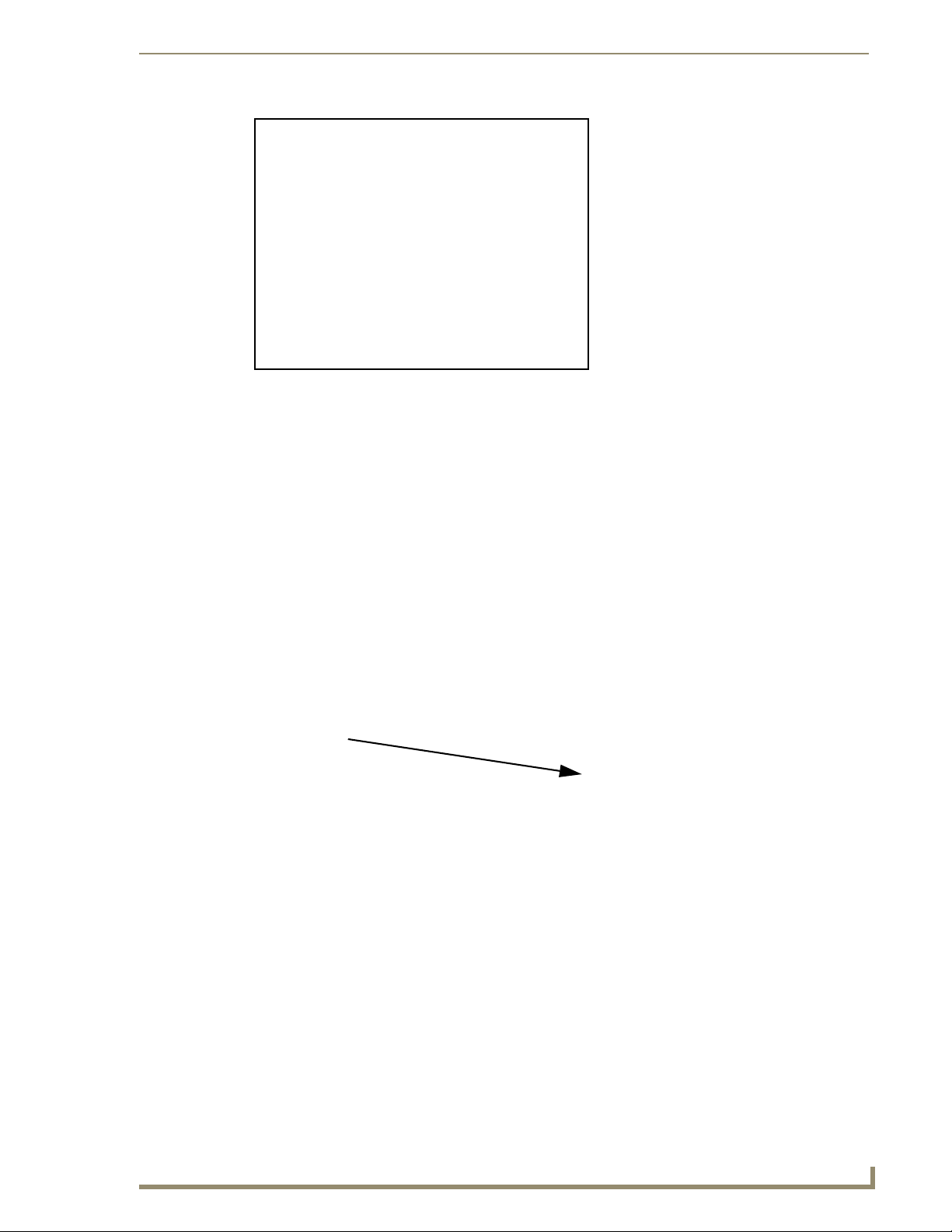
Configuring Communication
FIG. 28 G4 Web Control page
7. The Network Interface Select field is read-only for the TPI/4 and uses Wired as the default method
of communication to the web.
Wired is used when a direct Ethernet connection is being used for communication to the web.
This is the default setting if either no wireless interface card is detected or if both an Ethernet
and wireless card connection is detected by the panel.
The Wireless option is unavailable within TPI/4.
8. Press the Web Control Name field to open the Web Name keyboard.
9. From the Web Name keyboard, enter a unique alpha-numeric string to identify the TPI/4. This
information is used by the NetLinx Security Web Server to display on-screen links to the
unit.
The on-screen links use the IP Address of the panel and not the name for communication
(FIG. 29).
FIG. 29 Sample relationship between G4 Web Control and Mange WebControl Connections window
10. Press Done after you are finished assigning the alpha-numeric string for the Web Control name.
11. Press the Web Control Password field to open the Web Password keyboard.
12. From the Web Password keyboard, enter a unique alpha-numeric string to be assigned as the G4
Authentication session password associated with VNC web access of this TPI/4.
13. Press Done after you are finished assigning the alpha-numeric string for the Web Control password.
14. Press the Web Control Port field to open the Web Port Number keypad.
15. Within the keypad, enter a unique numeric value to be assigned to the port the VNC Web Server is
running on. The default value is 5900.
NXP-TPI/4 NetLinx Touch Panel Interface
43
Page 50

Configuring Communication
16. Press Done when you are finished entering the value. The remaining fields within the G4 Web
Control Settings section of this page are read-only and cannot be altered.
17. Press the Up/Down arrows on either sides of the G4 Web Control Tim eout field to increase or
decrease the amount of time the panel can remain idle (no cursor movements) before the session is
closed and the user is disconnected.
18. Press the Back button to open the Protected Setup page.
19. Press the on-screen Reboot button to save any changes and restart the TPI/4.
Verify your NetLinx Master’s IP Address and System Number have been properly
entered into the Master Connection section of the System Connection page.
Using your NetLinx Master to Control the Unit
Refer to your particular NetLinx Master’s instruction manual for detailed information on how to
download the latest firmware from www.amx.com. This firmware build enables SSL certificate
identification and encryption, HTTPS communication, ICSP data encryption, and disables the ability to
alter the Master security properties via a TELNET session.
In order to fully utilize the SSL encryption, your web browser should incorporate the
an encryption feature. This encryption level is displayed as a Cipher strength.
Once the Master’s IP Address has been set through NetLinx Studio (version 2.x or higher):
1. Launch your web browser.
2. Enter the IP Address of the target Master (ex: http://198.198.99.99) into the web browser’s Address
field.
3. Press the Enter key on your keyboard to begin the communication process between the target
Master and your computer.
Initially, the Master Security option is disabled (from within the System Security page) and
no username and password is required for access or configuration.
Both HTTP and HTTPS Ports are enabled by default (via the Manage System > Server
page).
If the Master has been previously configured for secured communication, click OK to accept
the AMX SSL certificate (if SSL is enabled) and then enter a valid username and password
into the fields within the Login dialog.
4. Click OK to enter the information and proceed to the Master’s Manage WebControl Connections
window.
5. This Manage WebControl Connections page (FIG. 30) is accessed by clicking on the Manage
connections link (within the Web Control section within the Navigation frame). Once activated, this
page displays links to G4 panels running the latest G4 Web Control feature (previously setup and
activated on the panel).
6. Click on the G4 panel name link associated with the target panel. A secondary web browser window
then appears on the screen (FIG. 31).
44
NXP-TPI/4 NetLinx Touch Panel Interface
Page 51
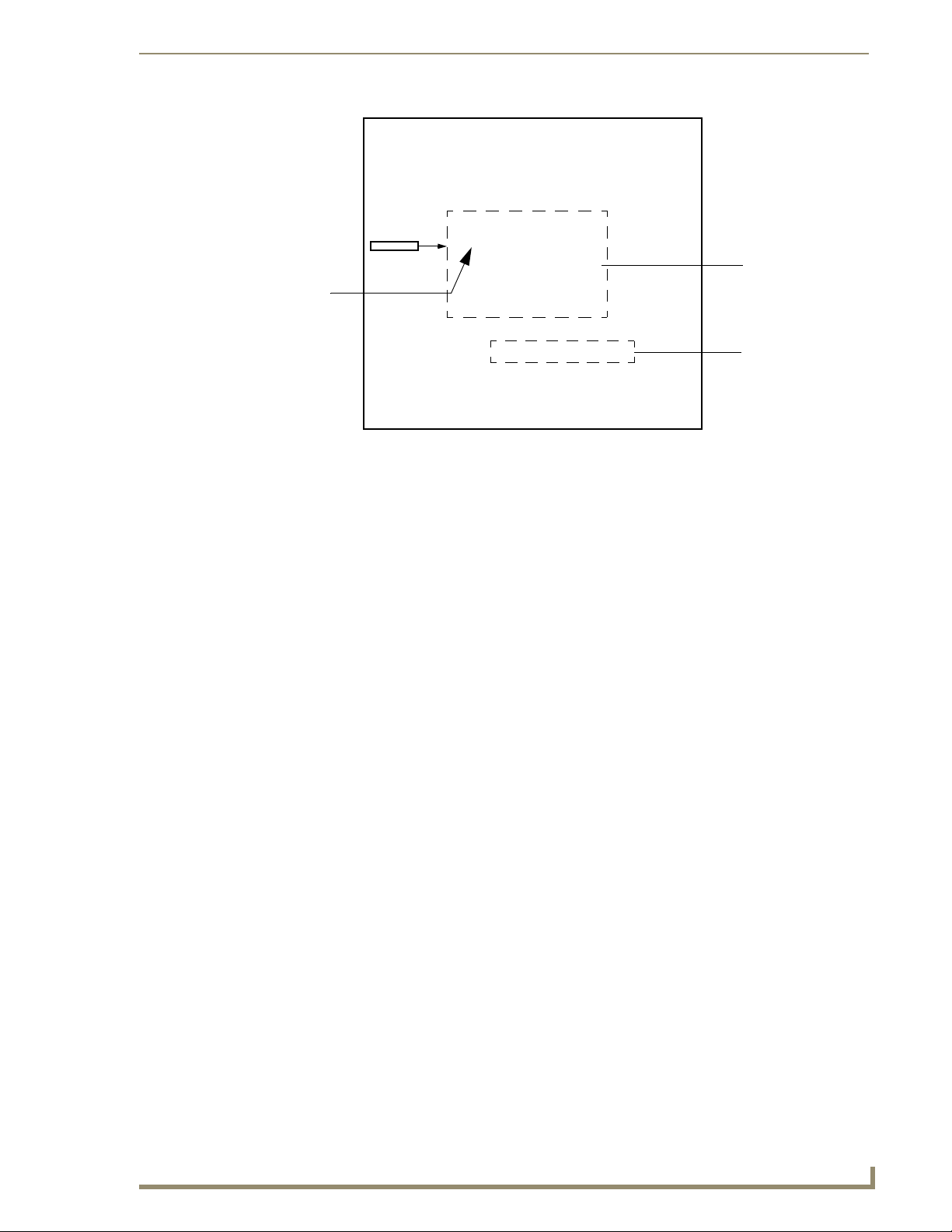
G4 panels
FIG. 30 Manage WebControl Connections page (populated with compatible panels)
Configuring Communication
Compatible
devices field
(showing G4
WebControl links)
Compression
Options
FIG. 31 Web Control VNC installation and Password entry screens
7. Click Ye s from the Security Alert popup window to agree to the installation of the G4 WebControl
application on your computer. This application contains the necessary Active X and VNC client
applications necessary to properly view and control the unit’s pages from your computer.
The G4 Web Control application is sent by the TPI/4 to the computer that is used for
communication. Once the application is installed, this popup will no longer appear.
This popup will only appear if you are connecting to the target panel using a different
computer.
8. In some cases, you might get a Connection Details dialog (FIG. 32) requesting a VNC Server IP
Address. This is the IP Address not the IP of the Master but of the target touch panel. Depending on
which method of communication you are using, it can be found in either the:
Wired Ethernet - System Connection > IP Settings section within the IP Address field.
If you do not get this field continue to step 9.
NXP-TPI/4 NetLinx Touch Panel Interface
45
Page 52

Configuring Communication
FIG. 32 Connection Details dialog
9. If a WebControl password was setup on the G4 WebControl page, a G4 Authentication Session
password dialog box appears on the screen within the secondary browser window.
10. Enter the Web Control session password into the Session password field (FIG. 31). This password
was previously entered into the Web Control Password field within the G4 Web Control page on the
TPI/4.
11. Click OK to send the password to the TPI/4 and begin the session. A confirmation message appears
stating "Please wait, Initial screen loading..".
The secondary window then becomes populated with the same G4 page being displayed on the target G4
panel. A small circle appears within the on-screen G4 panel page and corresponds to the location of the
mouse cursor. A left-mouse click on the computer-displayed panel page equates to an actual touch on the
target G4 panel page.
IP Address of touch panel
- obtained from IP Settings section of
the System Connection page
46
NXP-TPI/4 NetLinx Touch Panel Interface
Page 53

Upgrading TPI/4 Firmware
Before beginning the Upgrade process:
Setup and configure your NetLinx Master. Refer to your particular NetLinx Master instruction
manual for detailed setup procedures.
Select the correct resolution, touch drivers, and calibrate the TPI/4. Refer to the Step 3:
Calibrating the TPI/4 section on page 31.
Refer to the NetLinx Studio version 2.x or higher Help file for more information on uploading
files via Ethernet.
Configure your TPI/4 for direct communication. Refer to the Configuring
Communication section on page 33 for more detailed information about Ethernet or ICSNet
communication.
The process of updating firmware involves the use of a communicating NetLinx Master. The required
steps for updating firmware to a TPI/4 are virtually identical to those necessary for updating KIT files to
a NetLinx Master (except the target device is a panel instead of a Master). Refer to either your Master’s
literature or Studio 2.x Help file for those procedures.
Upgrading TPI/4 Firmware
A TPI/4 which is not using a valid username and password will not be able to
communicate with a secured Master. If you are updating the firmware on a TPI/4
which is not using a username or password field, you must first remove the Master
Security feature to establish an unsecured connection.
Upgrading the TPI/4 Firmware through an IP Address
Before beginning with this section, verify that your TPI/4 unit is powered and connected to the NetLinx
Master through either an Ethernet connection.
Step 1: Prepare the Master for communication through an IP
1.
Obtain the IP Address of the NetLinx Master from your System Administrator, if you do not have
an IP Address for the Master, refer to your particular Master’s instruction manual for more
information on obtaining an IP Address using NetLinx Studio 2.x or higher.
From the Online Tree tab of the Workspace window, select the NetLinx Master.
Follow steps outlined in either the Obtaining or Assigning the Master’s IP Address sections
from your particular NetLinx Master instruction manual to use an address.
Note the IP Address and Gateway information.
2. Launch NetLinx Studio 2 (default location is Start > Programs > AMX Control Disc > NetLinx
Studio 2 > NetLinx Studio 2).
3. Select Settings > Master Communication Settings, from the Main menu to open the Master
Communication Settings dialog (FIG. 33).
NXP-TPI/4 NetLinx Touch Panel Interface
47
Page 54

Upgrading TPI/4 Firmware
FIG. 33 Assigning Communication Settings and TCP/IP Settings
4. Click the Communications Settings button to open the Communications Settings dialog.
5. Click on the NetLinx Master radio button (from the Platform Selection section) to indicate that you
6. Click on the Authentication Required radio box (if the Master is secured) and then enter a
7. Click on the TCP/IP radio button (from the Transport Connection Option section) to indicate you
8. Click the Edit Settings button (on the Communications Settings dialog) to open the TCP/IP
9. From within the TCP/IP dialog click New to enter the IP information for a new IP Address or select
10. Enter the IP Address into the TCP/IP Address field. This information is obtained from either your
11. Click OK when you are done adding or editing the IP Address from the New/Edit TCP/IP Setting
12. Click OK three more times to close the open dialogs and save your settings.
13. Click Ye s to interrupt the current communication from the Master and apply the new settings.
14. Select Tools > Reboot the Master Controller to access the Reboot the Master dialog, then click
15. Once the dialog replies with "Reboot of system complete", press Done.
16. Click the OnLine Tree tab in the Workspace window to view the devices on the System. The default
17. Right-click on the Empty Device Tree/System entry and select Refresh System to re-populate the
List of previously saved IP Addresses
are working with a NetLinx Master (such as the NXC-ME260/64 or NI-Series of Integrated
Controllers).
username and password.
are connecting to the Master through an IP Address.
Settings dialog (FIG. 33).
from the list of previously entered IP Address and alter their properties by clicking the Edit button
and making your changes.
System Administrator or obtained from the Master.
dialog.
Reboot to reboot the Master and incorporate any changes.
System value is one.
list.
48
NXP-TPI/4 NetLinx Touch Panel Interface
Page 55
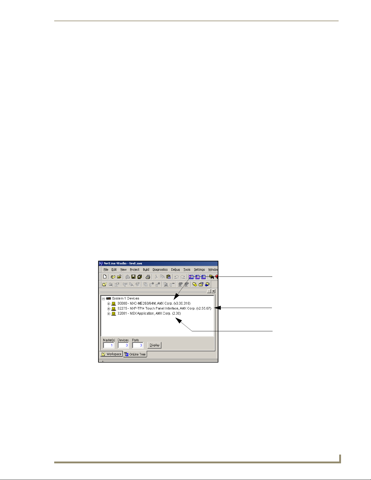
Upgrading TPI/4 Firmware
Step 2: Prepare the TPI/4 for communication via an IP
Press the blue ICSNet/Ethernet field (from the Master Connection section) until the choice cycles to
1.
the word Ethernet.
2. Press the Mode field until the choice cycles to the word URL.
By selecting URL, the System Number field becomes read-only (grey) because the panel pulls
this value directly from the communicating target Master (virtual or not). A virtual Master
system value can be set within the active AMX software applications such as: NetLinx Studio,
TPD4, or IREdit.
3. Press the blue Master IP/URL field to open a Keyboard and enter the NetLinx Master’s
IP Address (obtained from the Diagnostics - Networking Address dialog of the NetLinx Studio
application).
4. Click Done to accept the new value and return to the System Configuration page.
5. Do not alter the Master Port Number value (this is the default value used by NetLinx).
6. Press the on-screen Reboot button, from the Protected Setup page, to restart the TPI/4 and save any
changes.
Step 3: Verify and Upgrade the TPI/4 firmware via an IP
Click the OnLine Tree tab in the Workspace window to view the devices on the System. The default
1.
System value is one.
2. Right-click the associated System number (from the Workspace window) and select Refresh
System to detect of all devices on the current system, establish a new connection to the Master, and
refresh the System list with devices on that system.
3. After the Communication Verification dialog window verifies active communication between the
PC and the Master, verify the panel appears in the OnLine Tree tab of the Workspace window
(FIG. 34). The default TPI/4 panel value is 2275.
Showing a Master
firmware version and
device number
Showing the current TPI/4
firmware version and
device number
Shows NetLinx Studio
version number
FIG. 34 NetLinx Workspace window (showing connected TPI/4)
The TPI/4 firmware is shown on the right of the listed unit. New G4 firmware features
are available through firmware beginning with v2.XX.
4. If the firmware version is not the latest available; locate the latest firmware file from the
www.amx.com > Tech Center > Downloadable Files > Firmware Files > NXP-TPI/4 section of
the website.
NXP-TPI/4 NetLinx Touch Panel Interface
49
Page 56
Upgrading TPI/4 Firmware
5. Download the appropriate KIT file to your computer.
6. Verify you have downloaded the latest TPI/4 firmware (KIT) file to a known location.
7. Select Tools > Firmware Transfers > Send to NetLinx Device from the Main menu to open the
Send to NetLinx Device dialog (FIG. 35). Verify the TPI/4’s System and Device number values
match those values listed within the System folder in the OnLine Tree tab of the Workspace
window.
Selected Firmware file
FIG. 35 Select to NetLinx Device dialog (showing TPI/4 firmware update via IP)
Description field for selected KIT file
Firmware download
status
Device value and System number
must match the values
listed in the Workspace window
8. Select the TPI/4’s KIT file from the Files section (FIG. 35).
9. Enter the Device value associated with the TPI/4 and the System number associated with the Master
(listed in the OnLine Tree tab of the Workspace window). The Port field is greyed-out.
10. Click the Reboot Device checkbox. This causes the TPI/4 to reboot after the firmware update
process is complete. The reboot of the unit can take up 30 seconds after the firmware process has
finished.
11. Click Send to begin the transfer. The file transfer progress is indicated on the bottom-right of the
dialog (FIG. 35).
12. Click Close (after the unit reboots) to return to the main program.
13. Right-click the associated System number and select Refresh System. This causes a refresh of all
project systems, establishes a new connection to the Master, and populates the System list with
devices on your particular system.
50
NXP-TPI/4 NetLinx Touch Panel Interface
Page 57

Upgrading TPI/4 Firmware
Upgrading the TP4 Input Cards via an IP Address
The v 2.XX firmware KIT file (available at www.amx.com) upgrades any connected TP4 Input cards. If
there is both a TP4-RGB and TP4-VID card in a TPI/4, then the KIT file updates the firmware on both
cards. Note that if you later add additional cards, you should follow these update procedures again. The
following accessory devices are firmware upgradeable:
TP4-RGB TPI/4 Input Card (FG2275-20)
TP4-VID TPI/4 Input Card (FG2275-10)
These devices are not given unique device numbers which would ordinarily appear within the Online
Tree tab of NetLinx Studio. They appear as part of device which they are connected
(TP4-RGB and TP4-VID) as seen below in FIG. 36. Each card has its own Adjustment page: the TP4-
RGB has the RGB Adjustment page (seen below) while the TP4-VID card has the Video Adjustment
page.
Target TPI/4 Device #
TP4-RGB
firmware
NetLinx Studio Online Tree tab Accessory’s corresponding firmware page
FIG. 36 Location of Firmware version information within NetLinx Studio and Firmware page
The only way to upgrade the firmware of an accessory item is to send the accessory’s firmware through a
target G4 device (such as the TPI/4). Its the TPI/4’s device number which is entered within the Send to
NetLinx Device transfer dialog in Studio.
Step 1: Prepare the cards for firmware transfer
Before beginning this section:
Refer to the Removing TP4 Input Cards section on page 15 for installation procedures.
Verify your cards are properly installed and that all connectors are securely fastened.
1. Identify the Device number of the target TPI/4 being used for firmware routing to the accessories.
2. Complete the instructions for configuring the NetLinx Master for IP communication found in the
Step 1: Prepare the Master for communication through an IP section on page 47.
3. Press the front panel SETUP button to open the Setup page.
4. Confirm the current firmware version on the cards by pressing the Video Adjustment button and
then the corresponding Slot # button of the target TP4 card. This action opens the corresponding
Adjustment pages (FIG. 37). The slots for these cards are labeled at the rear of the unit.
NXP-TPI/4 NetLinx Touch Panel Interface
51
Page 58

Upgrading TPI/4 Firmware
Firmware version of the TP4-RGB card
Output resolution
TP4-RGB Adjustment page
Incoming signal shown in the background
Firmware version of the TP4-RGB card
TP4-VID Adjustment page
Incoming signal shown in the background
FIG. 37 RGB and Video Adjustment pages (showing the default values)
Step 2: Upgrade the input card firmware via an IP
Click the OnLine Tree tab in the Workspace window to view the devices on the System.
1.
The default System value is one.
2. Right-click the associated System number (from the Workspace) and select Refresh System to
detect of all devices on the current system, establish a new connection to the Master, and refresh the
System list with devices on that system.
3. After the Communication Verification dialog window verifies active communication between the
PC and the Master, verify the TPI/4 appears in the OnLine Tree tab of the Workspace window.
The default TPI/4 panel value is 2275. The TP4 Input Cards will not appear on the system listing.
4. Locate the latest firmware file from the www.amx.com > Tech Center > Downloadable Files >
Firmware Files > NXP-TPI/4 - Input Card Firmware section of the website.
5. Download the appropriate KIT file to your computer.
6. Verify you have downloaded the latest input card firmware (KIT) file to a known location.
7. Select Tools > Firmware Transfers > Send to NetLinx Device from the Main menu to open the
Send to NetLinx Device dialog (FIG. 38). Verify the TPI/4’s System and Device number values
match those values listed within the System folder in the OnLine Tree tab of the Workspace
window.
8. Select the TP4 Input Card’s KIT file from the Files section of the dialog.
9. Enter the Device value associated with the TPI/4 and the System number associated with the Master
(listed in the OnLine Tree tab of the Workspace window). The Port field is greyed-out.
52
NXP-TPI/4 NetLinx Touch Panel Interface
Page 59

Upgrading TPI/4 Firmware
Selected Battery Base Firmware file
FIG. 38 Send to NetLinx Device dialog (showing NXA-BASE/B firmware update via IP)
Description field for selected KIT file
Firmware download
status
Device value and System number
must match the values
listed in the Workspace window
The firmware for the input card can not be downloaded directly. Download of the KIT
file to the cards is done through the TPI/4. The procedures for updating firmware to
the cards is nearly identical to those for updating TPI/4 firmware, except that the KIT
file selected must be that of the particular card(s).
10. Click the Reboot Device checkbox. This causes the TPI/4 to reboot after the firmware update
process is complete. The reboot of the unit can take up 30 seconds after the firmware process has
finished.
11. Click Send to begin the transfer. The file transfer progress is indicated on the bottom-right of the
dialog.
12. Click Close on the Send to NetLinx dialog window (after the TPI/4 reboots) to return to the main
program.
13. Right-click the associated System number and select Refresh System. This causes a refresh of all
project systems, establishes a new connection to the Master, and populates the System list with
devices on your particular system.
14. Press the front panel SETUP button (on the TPI/4) to navigate to the Setup page.
15. Confirm the current firmware version on the cards by pressing the Video Adjustment button and
then the corresponding Slot # button of the target TP4 card.
NXP-TPI/4 NetLinx Touch Panel Interface
53
Page 60

Upgrading TPI/4 Firmware
54
NXP-TPI/4 NetLinx Touch Panel Interface
Page 61

Firmware Pages and Descriptions
This section describes each G4 firmware page and their specific functional elements. The
NXP-TPI/4 is a G4 device that utilizes specific G4 pages.
Setup Navigation Buttons
The G4 Setup Navigation Buttons (FIG. 39) appear on the left of the panel screen when the Setup page is
currently active.
NXP-TPI/4 Setup
Navigation Buttons
Firmware Pages and Descriptions
FIG. 39 G4 Setup Navigation Buttons
These Navigation Buttons are specific to the NXP-TPI/4 and include the device specific elements
described in the following table:
G4 Setup Navigation Button Elements
Project Information: Press the Project Information button to access the Project Information and view
the TPD4 project file properties currently loaded on the NXP-TPI/4 (read-only).
• Refer to the Project Information Page section on page 58 for more detailed
information.
Panel Information: Press the Panel Information button to access the Panel Information page and
Time Adjustment: Press the Time Adjustment button to access the Time Adjustment page where
Audio Adjustments: Press the Audio Adjustment button to access the Volume page where you can
Protected Setup: Press the Protected Setup button to access the Protected Setup page section
view device specific information such as resolution, memory, etc. (read-only).
• Refer to the Panel Information Page section on page 59 for more detailed
information.
you can alter the time and date settings on the Master.
• Refer to the Time & Date Setup Page section on page 60 for more detailed
information.
alter the audio parameters on the TPI/4.
• Refer to the Volume Page section on page 61 for more detailed information.
that provides access to the TPI/4’s Web Control, calibration features, and
connection settings.
• Refer to the Protected Setup Page section on page 69 for more detailed
information.
NXP-TPI/4 NetLinx Touch Panel Interface
55
Page 62

Firmware Pages and Descriptions
G4 Setup Navigation Button Elements (Cont.)
Video Adjustment: Press the Video Adjustment button to access the main video page (either Video
Setup Page
The page (FIG. 40) centers around the basic properties used by the touch device connected to the
NXP-TPI/4 such as: Connection Status of the TPI/4, Display Timeout, Inactivity Page Flip Time, and
Inactivity page file information for the TPI/4 device.
Setup for a TP4-VID or RGB Setup for a TP4-RGB) where you can set the
video properties for incoming signal.
• The displayed page is associated to the TP4 card being used on a selected
Slot ID (default = Slot 1).
• A TPI/4 can use any combination of up to four (4) TP4 cards
(TP4-RGB or TP4-VID).
• Refer to the Video Adjustment - Video Adjustment section on page 63 for
more detailed information.
Connection Status
Red Connection Status icon -
indicates no connection to
a Master
Green Connection Status icon -
indicates communication
to a Master
FIG. 40
Setup page
The elements of the Setup page are described in the table below:
Setup Page Elements
Exit: Returns you to the Main touch panel page. In this case, the previous page is the
default Main page.
Connection Status icon: This visual display of the connection status allows the user to have a current
update of the TPI/4’s connection status regardless of what page is currently
active.
• A Lock only appears on the icon if the TPI/4 has established a connection with
a currently secured target Master (requiring a username and password).
56
NXP-TPI/4 NetLinx Touch Panel Interface
Page 63

Firmware Pages and Descriptions
Setup Page Elements (Cont.)
Connection Status: Displays whether the G4 device is communicating externally, the encryption
Display/Panel Timeout: Sets the length of time the TPI/4 can remain idle before activating the sleep
Inactivity Page Flip
Timeout:
Inactivity Page Flip
Timeout:
status of the communicating Master, what connection type is being used
(Ethernet or ICSNet), and what System the unit is a part of.
This visual display of the connection status is also reflected at the upper-right of
each firmware page. This allows the user to have a current visual update of the
panel’s connection status regardless of what page is currently active.
• The message displayed is either: "Connected via Ethernet" or "Connected via
ICSNet".
• If no connection can be established by the TPI/4, it will continue to try and
establish a connection while displaying: "Attempting via ....".
• The word "Encrypted" appears only when an encrypted connection is
established with a target Master.
• The G4 device must be rebooted before incorporating any panel
communication changes and detecting any active ICSNET/Ethernet
connections.
The ICSNet or Ethernet connection is not detected until after a reboot.
mode. When the device goes into sleep mode, the LCD is powered-down.
• Press the UP/DN buttons to increase/decrease the time until the TPI/4
times out. Range = 0 - 240 minutes.
• Use this button to set the timeout value to zero and disable the sleep mode.
Sets the number of minutes of inactivity before the TPI4 automatically flips to a
pre-selected touch panel page. When the device goes into this inactivity mode,
the LCD does not power-down.
• Press the UP/DN buttons to increase/decrease the time the TPI/4 can remain
inactive before it flips to the preset page. Range = 0 - 240 minutes.
• Use this button to set the timeout value to zero and disable the sleep mode.
Sets the number of minutes of inactivity before the G4 device automatically flips
to a pre-selected touch panel page. When the device goes into this inactivity
mode, the LCD does not power-down.
• Press the UP/DN buttons to increase/decrease the time the panel can remain
inactive before it flips to the preset page. Range = 0 - 240 minutes.
• Use this button to set the timeout value to zero and disable the inactivity page
flip mode.
• The touch panel page used for the Inactivity page flip is shown within a small
Inactivity Page field.
NXP-TPI/4 NetLinx Touch Panel Interface
57
Page 64

Firmware Pages and Descriptions
Project Information Page
The Project Information page displays the TPDesign4 (TPD4) project file properties currently loaded on
the selected TPI/4 (FIG. 41). Refer to the TPDesign4 Touch Panel Program instruction manual for more
specific information on uploading TPDesign4 files to a panel.
FIG. 41 Project Information page
The elements of the Project Information page are described in the table below:
Sample TPD4 Project Properties dialog
Project Information Page Elements
Back: Returns you to the previously active touch panel page.
Connection Status icon: This visual display of the connection status allows the user to have a current
update of the TPI/4’s connection status regardless of what page is currently
active.
• A Lock only appears on the icon if the TPI/4 has established a connection with
a currently secured target Master (requiring a username and password).
File Name: Displays the name of the TPDesign4 project file downloaded to the NXP-TPI/4.
Designer ID: Displays the designer information.
File Revision: Displays the revision number of the file.
Dealer ID: Displays the dealer ID number (unique to every dealer and entered in TPD4).
Job Name: Displays the job name.
Sales Order: Displays the sales order information.
Purchase Order: Displays the purchase order information.
Build Number: Displays the build number information of the TPD4 software used to create the
Creation Date: Displays the project creation date.
Revision Date: Displays the last revision date for the project.
Last Save Date: Displays the last date the project was saved.
Blink Rate: Displays the feedback blink rate (10th of second).
Job Comments: Displays any comments associated to the job. These comments are taken from
project file.
the TPD4 project file.
58
NXP-TPI/4 NetLinx Touch Panel Interface
Page 65
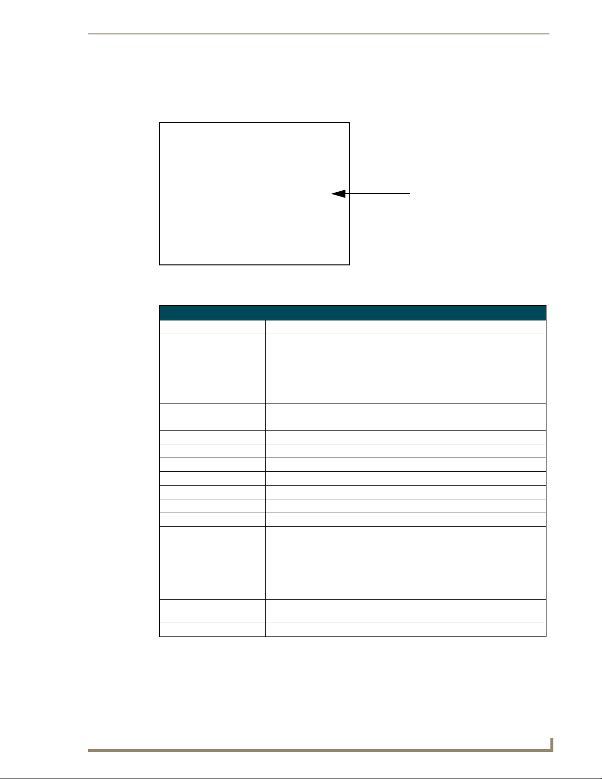
Firmware Pages and Descriptions
Panel Information Page
The Panel Information page (FIG. 42) centers around TPI/4 properties such as: resolution used,
on-board memory, firmware, address/channel information, and string information.
This information is retrieved from
the TPI/4 unit
FIG. 42 Panel Information page (takes its’ information from the TPI/4 device)
The elements of the Panel Information page are described in the table below:
Panel Information Page Elements
Back: Returns you to the previously active touch panel page.
Connection Status icon: This visual display of the connection status allows the user to have a current
update of the TPI/4’s connection status regardless of what page is currently
active.
• A Lock only appears on the icon if the TPI/4 has established a connection with
a currently secured target Master (requiring a username and password).
Panel Type: Displays the type of G4 device being used.
Firmware Version: Displays the G4 firmware version being used by the G4 device.
• Verify you have the latest version from www.amx.com.
Setup Port: Displays the setup port information/value being used by the TPI/4.
High Port: Displays the high port (port count) value for the TPI/4.
High Address: Displays the high address (address count) value for the TPI/4.
High Channel: Displays the high channel (channel count) value for the TPI/4.
High Level: Displays the high level (level count) value being used by the TPI/4.
Serial Number: Displays the specific serial number value assigned to the TPI/4.
Setup Pages Version: Displays the type and version of the Setup pages being used by the TPI/4.
Screen Width: Displays the pixel width being used to display the incoming video signal on the
G4 device.
• Maximum available screen width on a TPI/4 is 1280 pixels.
Screen Height: Displays the pixel height being used to display the incoming video signal on the
G4 device.
• Maximum available screen height on a TPI/4 is 1024 pixels.
Screen Refresh Rate: Displays the video refresh rate applied to the incoming video signal from the
Screen Rotation: Displays the degree of rotation applied to the on-screen image.
G4 device.
NXP-TPI/4 NetLinx Touch Panel Interface
59
Page 66
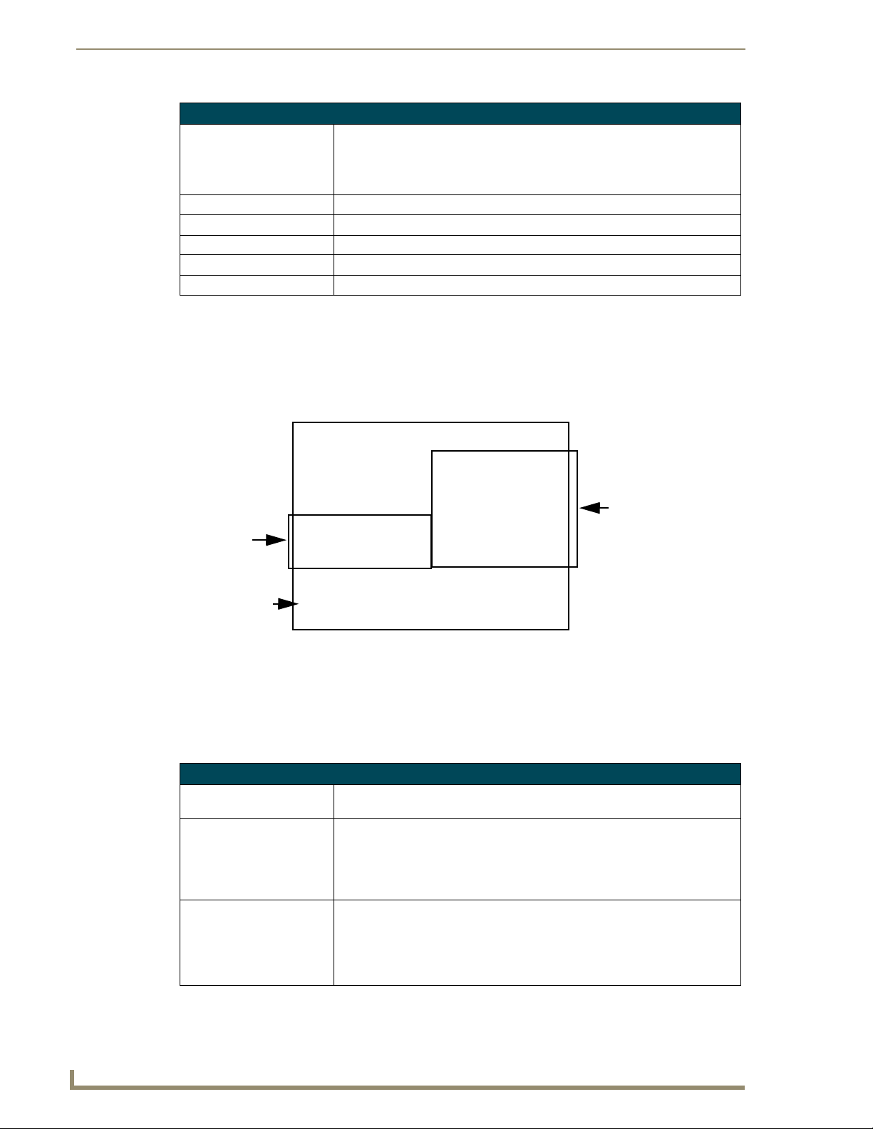
Firmware Pages and Descriptions
Panel Information Page Elements (Cont.)
Power Up Page: Displays the first touch panel page assigned for display after the device is
Start Up String: Displays the start-up string.
Wake Up String: Displays the wake up string used after an activation from a timeout.
Sleep String: Displays the sleep string used during the device’s sleep mode.
File System: Displays the amount of Compact Flash memory available on the TPI/4.
RAM: Displays the available RAM (or Extended Memory module) on the TPI/4.
Time & Date Setup Page
The Time & Date Setup page (FIG. 43) allows you to alter/set the time and date information on
the NetLinx Master. If either the Time/Date is modified on this page (then updated to the Master by
pressing the Set Time button), all devices communicating to that target Master will then be updated to
reflect the new information.
powered-up.
• This information is taken from the TPD4 project file.
• Most projects begin with a Main page.
Date Display
fields
Time Display
fields
Currently
selected
FIG. 43
Time and Date Setup page (takes its’ information from the TPI/4 device)
The only way to modify a TPI/4’s time, without altering the Master, is to use NetLinx
Code.
The elements of the Time & Date Setup page are described in the table below:
Time & Date Setup Page Elements
Back: Returns you to the previously active touch panel page without saving changes
Connection Status icon: This visual display of the connection status allows the user to have a current
Time Date Refresh/Set: This section provides you with two options:
(to save changes, use the Set Time button).
update of the TPI/4’s connection status regardless of what page is currently
active.
• A Lock only appears on the icon if the TPI/4 has established a connection with
a currently secured target Master (requiring a username and password).
• The Get Time/Date button retrieves the Time and Date information from the
Master.
• The Set Time/Date button sets the Master to retain and save any
time/date modifications made on the Time and Date Setup page.
60
NXP-TPI/4 NetLinx Touch Panel Interface
Page 67

Firmware Pages and Descriptions
Time & Date Setup Page Elements (Cont.)
Time Display fields: • These fields display the time in three formats: STANDARD, STANDARD
Date Display fields: • These fields display the calendar date information in several different formats.
Set Date/Time: This section provides a user with both UP/DN arrow buttons to alter the
AM/PM, and 24 HOUR.
Master’s calendar date and time. The blue circle indicates which field is
currently selected.
• Select the Year field and use the UP/DN buttons to alter the year value
(range = 2000 - 2037).
• Select the Month field and use the UP/DN buttons to alter the month value
(range = 1 - 12).
• Select the Day field and use the UP/DN buttons to alter the day value
(range = 1 - 31).
• Select the Hour field and use the UP/DN buttons to alter the hour value
(24-hour military).
• Select the Minute field and use the UP/DN buttons to alter the minute value
(range = 0 - 59).
• Select the Second field and use the UP/DN buttons to alter the second value
(range = 0 - 59).
The TPI/4 does not have an on-board clock. This page both receives and sets the
time/date of the NetLinx Master.
Volume Page
The Volume page (FIG. 44) (accessed by pressing the Audio Adjustments button on the Setup page)
allows you to adjust the master volume parameters and default panel sounds on the TPI/4.
FIG. 44 Volume configuration page
The elements of the Volume page are described in the table below:
Volume Page Elements
Exit: Saves the changes and returns you to the previously active touch panel page.
Connection Status icon: This visual display of the connection status allows the user to have a current
update of the TPI/4’s connection status regardless of what page is currently
active.
• A Lock only appears on the icon if the TPI/4 has established a connection with
a currently secured target Master (requiring a username and password).
NXP-TPI/4 NetLinx Touch Panel Interface
61
Page 68
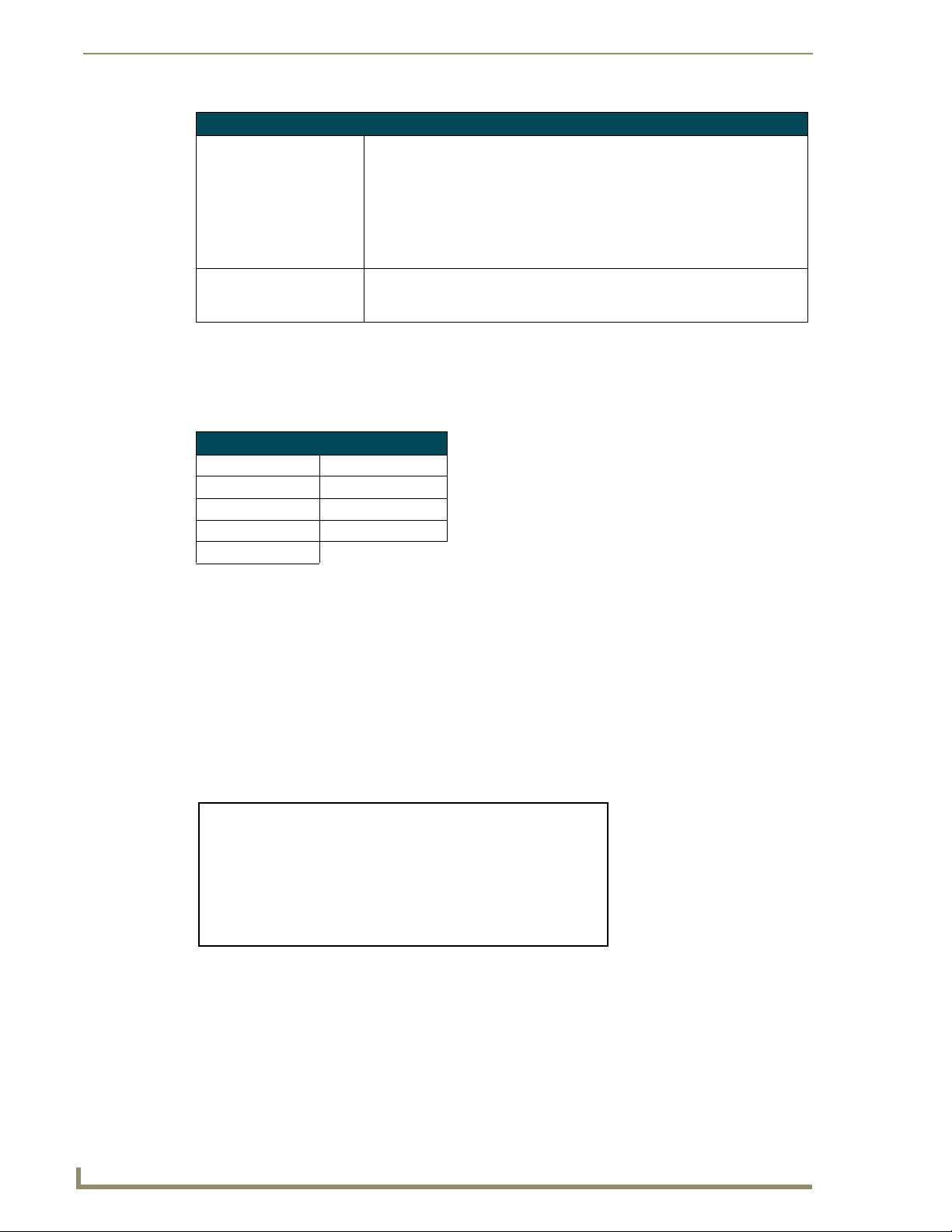
Firmware Pages and Descriptions
Volume Page Elements (Cont.)
Panel Volume: This section allows you to adjust the current sound level on the unit’s internal
Default Panel Sounds: Sets the unit to play either the default Button Hit sound (when you touch an
Supported sampling rates for WAV
The following is a listing of supported sampling rates associated for WAV files played on this G4 unit.
Some WAV files currently played on other devices may not work on this unit. The supported sampling
rates for WAV files are:
Supported WAV Sampling Rates
• 48000 Hz • 16000 Hz
• 44100 Hz • 12000 Hz
• 32000 Hz • 11025 Hz
• 24000 Hz • 8000 Hz
• 22050 Hz
speaker:
• Use the UP/DN buttons to adjust the volume output on the internal speakers
(range = 0 - 100).
• The Internal Sound Level bargraph indicates the current sound level.
• The Mute button mutes the volume.
• The Play Test button plays a test WAV/MP3 file over the internal speakers.
active button) and/or the default Button Miss sound (when you touch a
non-active button or any area outside of the active button).
Protected Setup Page
This button opens the Protected Setup page which centers around the properties used by the panel to
properly communicate with the NetLinx Master. Refer to the Protected Setup Navigation Buttons section
on page 68 for more detailed information.
Video Adjustment Slide-Out Option Bar
Pressing the on-screen Video Adjustment button causes an option bar to slide outwards from the
Navigation buttons (FIG. 45). This option bar provides you with the ability to select/adjust the properties
for the TP4 card connected to the selected slot number and displays the corresponding Adjustment page.
Refer to the following sections for detailed information.
FIG. 45
Video Adjustment Slide-Out Options Bar
The selection of a Slot # allows you to view/alter the properties of a TP4 card connected to the
TPI/4 motherboard on the selected input card slot (Slot ID). The default input slot that is first detected is
SLOT 1. The page displayed depends on the TP4 card being used in the selected Slot ID:
62
NXP-TPI/4 NetLinx Touch Panel Interface
Page 69

Firmware Pages and Descriptions
If a Slot ID contains no TP4 card the corresponding Slot buttons (FIG. 45) will be greyed-out.
The RGB Adjustment page appears when the selected (or default) input slot is using a
TP4-RGB card.
The Video Adjustment page appears when the selected (or default) input slot is using a TP4-
VID card.
Video Adjustment - Video Adjustment
The Video Adjustment page (FIG. 46) (accessed by pressing the Video Adjustment button on the Setup
page and then selecting a SLOT # from the option bar which contains a TP4-VID card) sets the Video
properties of the incoming video signal. These slots are labeled at the rear of the unit.
Incoming Video signal
Once done making your screen
adjustments, SAVE SETTINGS.
FIG. 46 Video Adjustment page (showing default values)
The elements of the Video Adjustment page are described in the table below:
Video Adjustment Page Elements
Back: Saves the changes and returns you to the previously active touch panel page.
Connection Status icon: This visual display of the connection status allows the user to have a current
Settings: • The Default Settings button sets the video settings to their default values
Video Settings: • The Black & White button toggles the Black & White display mode.
Status: Displays whether or not a video-sync signal is detected.
Ver sio n: Displays the firmware version being used by the selected TP4-VID card.
update of the TPI/4’s connection status regardless of what page is currently
active.
• A Lock only appears on the icon if the TPI/4 has established a connection with
a currently secured target Master (requiring a username and password).
(indicated in this table).
• The Undo Changes button disregards any changes made on the page since
the last settings were saved.
• The Save Settings button saves any changes made to this page.
Default = Off.
• The Sharpness button toggles the Interpolate (Sharpness) feature.
Default = Off.
•The Interlace button toggles the Interlacing feature.
Default = Off.
NXP-TPI/4 NetLinx Touch Panel Interface
63
Page 70
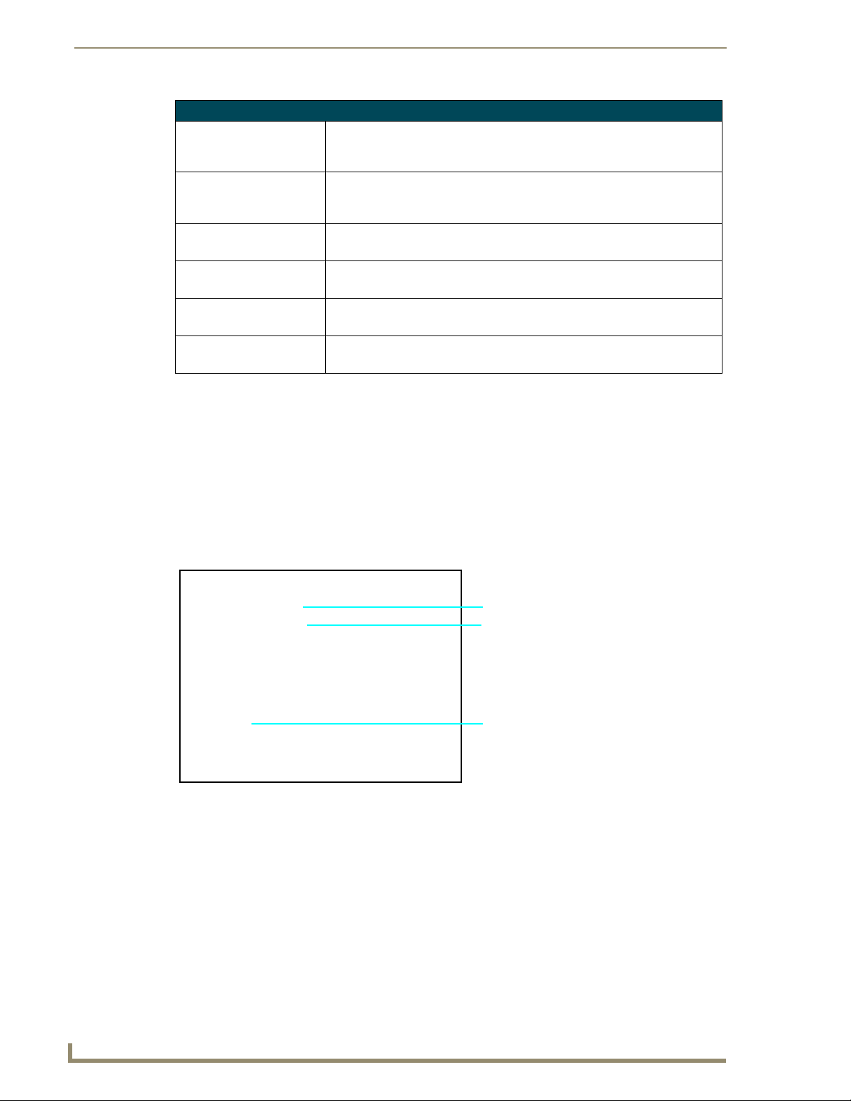
Firmware Pages and Descriptions
Video Adjustment Page Elements (Cont.)
Format: Allows you to press this blue field and cycle through a choice of available video
Input: Allows you to cycle through a choice of available video inputs
Brightness: Use the UP/DN buttons to alter the brightness level of the incoming signal.
Contrast: Use the UP/DN buttons to alter the contrast level of the incoming signal.
Saturation: Use the UP/DN buttons to alter the color saturation level of the incoming signal.
Hue: Use the UP/DN buttons to alter the hue level of the incoming signal.
If the TPI/4 is powered Off, any preset TPD4 Video pages must be reset if you are
using an S-Video input.
By default, the Input is set to Composite. If the video pages appear blank upon
restart of the unit, simply toggle the Input setting to S-Video.
formats (NTSC, PAL , SECAM, or Auto detect).
• Default = Auto.
(either Composite or S-Video).
• Default = Composite.
• Range = 0 - 255, default = 128.
• Range = 0 - 255, default = 128.
• Range = 0 - 255, default = 128.
• Range = 0 - 255, default = 128.
Video Adjustment - RGB Setup
The RGB Setup page (FIG. 47) (accessed by pressing the Video Adjustment button on the Setup page and
then selecting a SLOT # from the option bar which contains a TP4-RGB card) sets the RGB properties of
the incoming signal. These slots are labeled at the rear of the unit.
Firmware version of TP4-RGB card
Output resolution
Once you are done making your
adjustments, click SAVE SETTINGS.
Incoming signal shown in the background
Pressing this area activates the
Full Screen Edit mode
FIG. 47 RGB Adjustment page (showing the default values)
64
NXP-TPI/4 NetLinx Touch Panel Interface
Page 71

Firmware Pages and Descriptions
The elements of the RGB Adjustment page are described in the table below:
RGB Adjustment Page Elements
Back: Saves the changes and returns you to the previously active touch panel page.
Connection Status icon: This visual display of the connection status allows the user to have a current
update of the TPI/4’s connection status regardless of what page is currently
active.
• A Lock only appears on the icon if the TPI/4 has established a connection with
a currently secured target Master (requiring a username and password).
Settings: • The Default Settings button sets the RGB settings to their default values
(indicated in this table).
• The Undo Changes button disregards any changes made on the page since
the last settings were saved.
• The Save Settings button saves any changes made to the RGB Adjustment
page.
• The Sync on Green button sets the TP4-RGB card to search for the sync
signal on Green signal.
Ver sio n: Displays the firmware version currently on the internal TP4-RGB card.
Status: Displays the input signal properties of the signal routed through the internal
Phase: Use the UP/DN buttons to alter the RGB tracking/signal level.
H Position: Use the UP/DN buttons to alter the horizontal position level.
H Size: Use the UP/DN buttons to alter the horizontal size level.
V Position: Use the UP/DN buttons to alter the vertical position level.
All Brightness: Use the UP/DN buttons to alter the overall brightness level of the selected video
Red Brightness Use the UP/DN buttons to alter the brightness of the red color value.
Green Brightness Use the UP/DN buttons to alter the brightness of the green color value.
Blue Brightness Use the UP/DN buttons to alter the brightness of the blue color value.
TP4-RGB card (H-pixel x V-pixel @ Hz). An example is: 1280x1024@75Hz.
• This is the property of the incoming signal and not the resolution of the TPI/4.
• Range = 0 - 31, default = 0.
• Range = 0 - 255, default = 0.
• Range = 0 - 255, default = 0.
• Range = 0 - 255, default = 0.
input (card).
• Range = 0 - 255.
• Range = 0 - 255, default = 127.
• For more accurate control, you will have to go into the Full Screen Edit Mode
described in the following section.
• Range = 0 - 255, default = 127.
• For more accurate control, you will have to go into the Full Screen Edit Mode
described in the following section.
• Range = 0 - 255, default = 127.
• For more accurate control, you will have to go into the Full Screen Edit Mode
described in the following section.
NXP-TPI/4 NetLinx Touch Panel Interface
65
Page 72

Firmware Pages and Descriptions
RGB Adjustment Page Elements (Cont.)
All Contrast: Use the UP/DN buttons to alter the overall contrast level of the selected video
Red Contrast Use the UP/DN buttons to alter the contrast of the red color value.
Green Contrast Use the UP/DN buttons to alter the contrast of the green color value.
Blue Contrast Use the UP/DN buttons to alter the contrast of the blue color value.
Full Screen Edit Mode: Pressing the incoming signal area (seen above) activates the Full Screen Edit
input (card).
• Range = 0 - 255.
• Range = 0 - 255, default = 127.
• For more accurate control, you will have to go into the Full Screen Edit Mode
described in the following section.
• Range = 0 - 255, default = 127.
• For more accurate control, you will have to go into the Full Screen Edit Mode
described in the following section.
• Range = 0 - 255, default = 127.
• For more accurate control, you will have to go into the Full Screen Edit Mode
described in the following section.
mode. The on-screen popup provides each field with UP/DN buttons to
more accurately adjust the values for all of the above mentioned RGB
parameter fields.
• This mode causes the incoming signal to be displayed at full screen and
places an RGB Adjustments bar on the bottom of the screen.
• Pressing the bar launches a draggable popup of all Adjustment buttons over
the full screen image.
• This popup allows you to view and alter the displayed image without having
the image blocked by the upper section of settings buttons.
Adjusting the Incoming Image on the RGB Adjustment Page
After opening the RGB Adjustment page, if the selected slot is receiving an RGB image, this image is
then displayed within the incoming signal area. By pressing this area, you are provided with a more
accurate method of altering the individual fields affecting the incoming image (using UP/DN arrows vs
the slider bar). The Full Screen Edit mode also allows you to more accurately judge any modifications
made to the incoming image by viewing the image at full screen and behind the RGB Adjustments
popup.
To adjust these properties:
1. Press the incoming signal area of the RGB Adjustments page to launch the Full Screen Edit mode,
display the incoming image at full screen, and place a grey RGB Adjustments bar on the bottom of
the screen.
One of the first things to look at when trying to adjust your image, is the Phase value.
Adjustments to this value can help troubleshoot most image issues.
2. Press this grey bar to maximize the RGB Adjustments popup menu (FIG. 48) which provides you
with much more accurate adjustments of the incoming signal properties. This menu can be dragged
across the screen for a better view of the underlying image. Once you exit this menu, the grey bar is
positioned back onto its original location.
66
NXP-TPI/4 NetLinx Touch Panel Interface
Page 73

Firmware Pages and Descriptions
On-screen image controls
(activated by pressing
the RGB Adjustments bar)
Incoming RGB signal
Once done making your screen
adjustments, SAVE SETTINGS.
FIG. 48 RGB Setup page-showing the Full Edit option with controls
Although these same options are available within the main RGB Adjustments page, these
RGB image controls provide you with UP/DN arrows for accurate value entry adjustments.
These controls allow you to set the RGB properties for the incoming
image/video on the selected TP4-RGB card within the selected Slot ID.
The incoming TPI/4 image must be first be adjusted (especially if using a CRT
monitor) to fit into the visible screen area. Refer to the TPI/4 and Panel Interface
Setup section on page 27 for more detailed information on adjusting the position and
size on a CRT monitor. When using a touch panel, the TOUCH DRIVER selected
should compensate for the visible area, if not, continue with these steps.
3. Use the UP/DN Phase buttons to alter the RGB tracking/signal level of the incoming
image/video. These values cycle back thru 0 and on after reaching 31.
4. Use the UP/DN H Position buttons to adjust the horizontal location and move the image
(left-right) on the screen. These values cycle back thru 0 and on after reaching 255.
5. Use the UP/DN H Size buttons to adjust the horizontal height and stretch the image on the screen.
These values cycle back thru 0 and on after reaching 255.
6. Use the UP/DN V Position buttons to adjust the vertical location and move the image
(up-down) on the screen. These values cycle back thru 0 and on after reaching 255.
7. Use the UP/DN Brightness buttons to adjust either the overall or individual Red, Green, and Blue
brightness of the incoming image/video. The All Brightness bargraph gives a visual representation
of the overall brightness level and cycles through an entire turn.
8. Use the UP/DN Contrast buttons to adjust the overall or individual Red, Green, and Blue contrast
of the incoming image/video. Increasing the value can increase sharpness. This All Contrast
bargraph gives a visual representation of the overall contrast level and cycles through an entire
turn.
9. Once done making these adjustments, press the Done button to temporarily save these modifications
and place the grey RGB Adjustments bar back onto the bottom of the screen. Pressing the Cancel
button returns you to the RGB Adjustments page without temporarily saving your changes.
10. Press anywhere on the background image to exit from the Full Screen Edit mode and return to the
RGB Adjustment page.
11. In the RGB Adjustment Page, press the Save Settings button to save your changes to the
TP4-RGB card. Cycling power to the panel before saving your settings can cause your pages to
shift back to their original locations.
12. Press the Back button to return to the Setup page.
NXP-TPI/4 NetLinx Touch Panel Interface
67
Page 74

Firmware Pages and Descriptions
Protected Setup Navigation Buttons
The Protected Setup Navigation Buttons (FIG. 49) appear on the left of the screen when the Protected
Setup page is currently active.
NXP-TPI/4 Protected
Setup Navigation
Buttons
FIG. 49 G4 Protected Setup Navigation Buttons
These Navigation Buttons are specific to the NXP-TPI/4 device and include the device specific elements
described in the following table:
G4 Protected Setup Navigation Button Elements
G4 Web Control: Press the G4 Web Control button to access the G4 Web Control page where
you can enable or disable display and control of your panel (via the web) by a
PC running a VNC client.
• Refer to the Using G4 Web Control to Interact with a G4 Panel section on
page 42 for more detailed information.
Passwords: Press the Passwords button to access the Passwords Setup page where you
can specify up to five security passwords. Default password is 1988.
• Refer to the Password Setup Page section on page 74 for more detailed
information.
Calibrate: Press the Calibrate button to access the Calibration page where you can use
System Connection: Press the System Connection button to access the System Connection page
the displayed set of crosshairs to calibrate a touch screen/panel.
• Refer to the Calibration Page section on page 74 for more detailed
information.
where you can alter the communication parameters of both the NetLinx
Master and TPI/4.
• Refer to the System Connection Page section on page 75 for more detailed
information.
68
NXP-TPI/4 NetLinx Touch Panel Interface
Page 75

Firmware Pages and Descriptions
Protected Setup Page
The Protected Setup page (FIG. 50) centers around the properties used by the NXP-TPI/4 to
communicate with the NetLinx Master. Enter the factory default password (1988) into the password
keypad to access this page.
FIG. 50 Protected Setup page
The elements of the Protected Setup page are described in the table below:
Protected Setup Page Elements
Back: Saves the changes and returns you to the previously active touch panel page.
Connection Status icon: This visual display of the connection status allows the user to have a current
update of the TPI/4’s connection status regardless of what page is currently
active.
• A Lock only appears on the icon if the TPI/4 has established a connection with
a currently secured target Master (requiring a username and password).
Device Number: Opens a keypad that is used to set and display the current device number.
Options: Allows you to select various TPI/4 features:
• The Function Show button enables the display of the channel port and
channel code in the top left corner of the button, the level port and level code
in the bottom left corner, and the address port and address code in the
bottom right corner (see FIG. 52 for an example of the function locations).
• Use the Page Tracking button to toggle page tracking. When enabled, the
TPI/4 sends page data back to the NetLinx Master, or vice versa depending
on the touch panel settings.
• Use the Te lnet button to enable or disable the telnet server on the TPI/4.
This feature focuses on direct telnet communication to the TPI/4.
Reboot Panel: Pressing this on-screen button causes the TPI/4 to restart after saving any
changes.
Serial Port Baud Rate: Use the Baud Rate UP/DN buttons to alter the baud rate for the front serial port.
The range is from 1200 - 115200.
• Default is 38400.
NXP-TPI/4 NetLinx Touch Panel Interface
69
Page 76

Firmware Pages and Descriptions
Protected Setup Page Elements (Cont.)
Touch Input Driver:
(TPI/4 only)
Displays the touch driver used by the TPI/4 to interact with the touch device.
The following list shows the series of available touch input drivers that are
selectable by using the TOUCH button on the front panel of the TPI/4:
- AMXDL15A: Selected when using an AMX DL15A touch panel.
®
- Cirque: Selected when using a Cirque
touch panel or other
compatible touch device driver.
- DynaPro: Selected when using either a DynaPro
®
touch panel or
other compatible DynaPro touch device driver.
®
- EloTouch: Selected when using either an ELO
touch panel or other
compatible ELO touch device driver (default).
- Elo19Touch: Selected when using a 19-inch ELO
®
touch panel or other
compatible ELO touch device driver.
- Eyegonomic: Selected when using either an Eyegonomic
®
touch panel
or other compatible Eyegonomic touch device driver.
®
- EZScreen: Selected when using either an EZScreen
touch panel or
other compatible EZScreen touch device driver.
- EZScreenV6: Selected when using either an EZScreenV6
®
touch panel
or other compatible EZScreen touch device driver.
- ISTTouch: Selected when using either an ISTTouch
®
touch panel or
other compatible IST touch device driver.
- Magnus: Selected when using either a Magnus touch panel or other
compatible Magnus device driver.
- MicroTouch: Selected when using either a MicroTouch
®
touch panel
or other compatible MicroTouch device driver.
- MicroTouchMT3000: Selected when using either a MicroTouchMT3000
model touch panel or other compatible MicroTouch device driver.
®
- MicroTouchPen: Selected when using either a MicroTouchPen
touch
device or other serial SMT3(R)/TouchPen4(+) driver.
- NullTouch: Selected when no touch driver is being used.
Use this option when working with a CRT monitor.
- SanyoTouch: Selected when using either a SanyoTouch
or other compatible Sanyo
- SerialMouse: Selected when using a Microsoft
®
touch device driver.
®
- SmartTech: Selected when using either a SmartTech
®
touch panel
compatible serial mouse.
®
touch panel or
other compatible SmartTech touch device driver.
®
- SyncMaster173v: Selected when using either a SyncMaster173v
touch panel or other compatible SyncMaster device driver.
- Wacom: Selected when using either a Wacom
®
touch panel or other
compatible Wacom touch device driver.
®
- Wacom2: Selected when using a Wacom
touch panel which requires the
use of additionally compatible Wacom touch device drivers.
• For updated touch driver info., visit www.amxs.com
®
70
NXP-TPI/4 NetLinx Touch Panel Interface
Page 77

Firmware Pages and Descriptions
Protected Setup Page Elements (Cont.)
System Recovery: Allows you to either reset the TPI/4 to factory default settings and/or wipe out all
existing touch panel pages:
• The Reset System Settings button allows a user to wipe out all current
configuration parameters on the TPI/4 (such as IP Addresses, Device
Number assignments, Passwords, and other presets).
- Pressing this button launches a Confirmation dialog (FIG. 51) which asks
you to confirm your selection.
- This dialog is configured with a delay timer that does not enable the YES
button for 5 seconds. This delay provides an additional amount of time for
the user to confirm their decision.
• The Remove User Pages button allows you remove all current TPD4 touch
panel pages currently on the TPI/4 (including the pre-installed AMX Demo
pages).
- Pressing this button launches a Confirmation dialog (FIG. 51) which asks
you to confirm your selection.
- This dialog is configured with a delay timer that does not enable the YES
button for 5 seconds. This delay provides an additional amount of time for
the user to confirm their decision.
FIG. 51
FIG. 52 Button/slider Function Show example
Protected Setup page-System Recovery confirmation dialog
Channel Port
3,132
Level Port
2,8 3,50
Channel Code
Number
Channel Code
Number
Button
Address
Por t
Address Code
Number
You have a wait time of 5 seconds
before the YES option is enabled.
Channel Port
Level Port
Channel Code
Number
7,10
4,9
Slider
Channel Code
Number
Address
Por t
1,8
Address Code
Number
NXP-TPI/4 NetLinx Touch Panel Interface
71
Page 78

Firmware Pages and Descriptions
G4 Web Control Page
The G4 Web Control page (FIG. 53) centers around enabling and disabling both the display and control
of your TPI/4 (via the web). An external PC running a VNC client (installed during the initial
communication to the G4 device) makes this possible.
FIG. 53 G4 Web Control page
Each G4 device supports the open standard Virtual Network Computing (VNC) interface. This device
contains a VNC server which allows it to accept a connection from any other device running a VNC
client. Once a connection is established to that target device, the client can control the TPI/4 remotely.
The elements of the G4 Web Control page are described in the table below:
G4 Web Control Page Elements
Back: Saves the changes and returns you to the previously active touch panel page.
Connection Status icon: This visual display of the connection status allows the user to have a current
update of the TPI/4’s connection status regardless of what page is currently
active.
• A Lock only appears on the icon if the TPI/4 has established a connection with
a currently secured target Master (requiring a username and password).
72
NXP-TPI/4 NetLinx Touch Panel Interface
Page 79

Firmware Pages and Descriptions
G4 Web Control Page Elements (Cont.)
G4 Web Control Settings: Sets the IP communication values for the TPI/4 and contains:
Enable/Enabled • The Enable/Enabled button allows you to toggle between the two G4
activation settings:
- Enable - deactivates the G4 Web Control feature on the TPI/4.
- Enabled - activates the G4 Web Control feature on the TPI/4 and allows
an external PC running a VNC client to access the unit (after the remaining
fields are configured).
Network Interface Select A read-only field that displays the method of communication to web.
• Wired is selected because it is the only method of communication to the web
(via a direct Ethernet connection). This is a default setting since no wireless
interface is available.
Web Control Name Allows you to enter a unique alpha-numeric string that is used as the display
name of the TPI/4 within the Web Control tab of the new NetLinx Security
browser window.
• This Web Control tab displays a G4 icon alongside the link to the Web Control
Name given to this TPI/4 (FIG. 54).
Web Control Password Allows you to enter the G4 Authentication session password associated for
VNC web access of this TPI/4.
Web Control Port Allows you to enter the port value that the VNC Web Server runs on.
• Default value is 5900.
Maximum Number of
Connections
Current Connection Count This read-only field displays the current number of users connected to the
G4 Web Control Timeout: Sets the length of time (in minutes) the TPI/4 can remain idle (no cursor
This read-only field displays the maximum number of users that can be
simultaneously connected to the target TPI/4 via the web.
• Default value is 1.
target TPI/4 via the web. This value cannot exceed the Maximum number field.
movements) before the session is closed and the user is disconnected.
• Minimum value = 0 minutes (panel never times-out)
• Maximum value = 240 minutes (panel times-out after 240 minutes/4hours)
FIG. 54
Sample relationship between G4 Web Control and Mange WebControl Connections window
Refer to the Using G4 Web Control to Interact with a G4 Panel section on page 42 for more detailed
instructions on how to use the G4 Web Control page with the new web-based NetLinx Security
application.
NXP-TPI/4 NetLinx Touch Panel Interface
73
Page 80
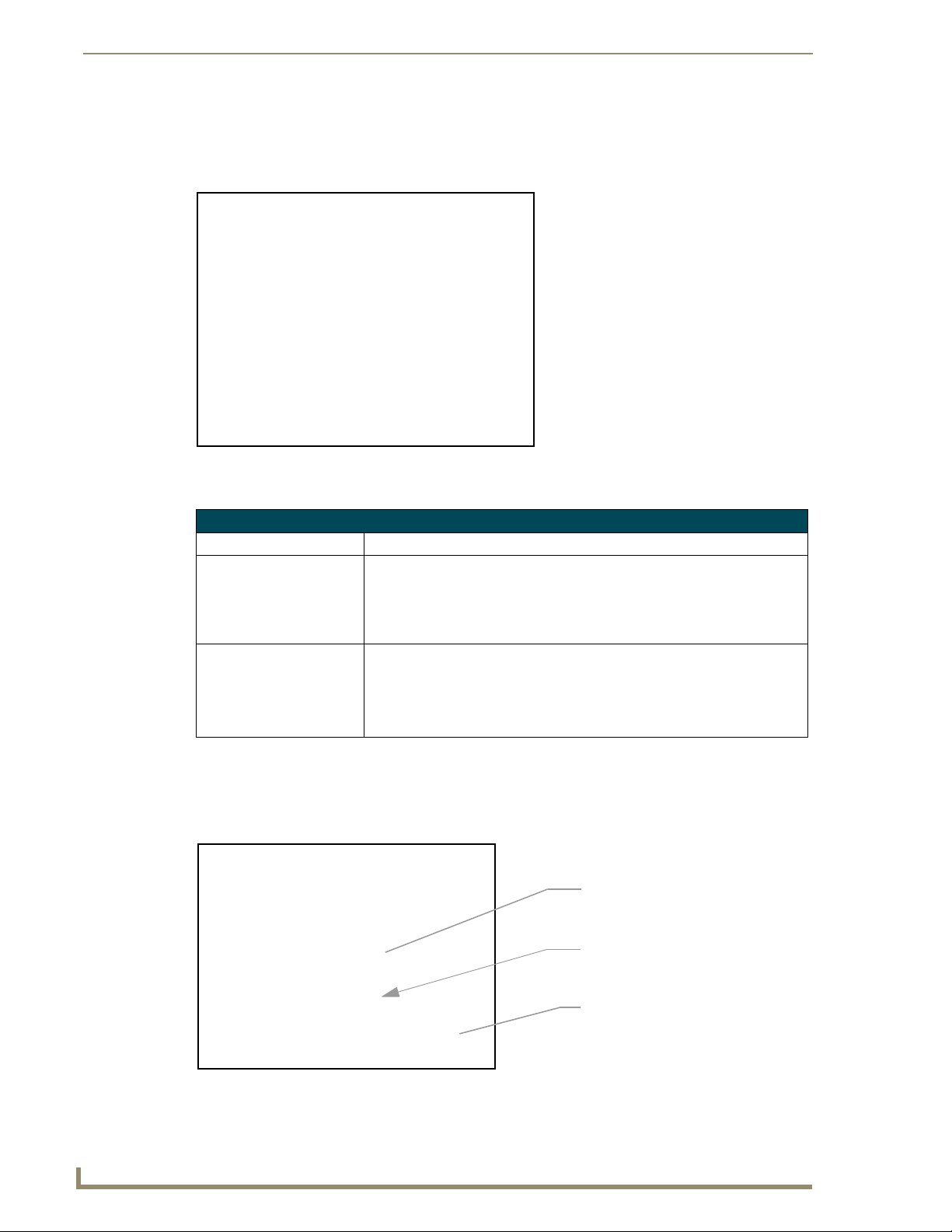
Firmware Pages and Descriptions
Password Setup Page
The Password Setup page (FIG. 55) centers around the properties used to assign passwords for the panel
pages.
FIG. 55 Password Setup page
The elements of the Password Setup page are described in the table below:
Password Setup Page Elements
Back: Saves the changes and returns you to the previously active touch panel page.
Connection Status icon: This visual display of the connection status allows the user to have a current
In Panel Password
Change:
update of the TPI/4’s connection status regardless of what page is currently
active.
• A Lock only appears on the icon if the TPI/4 has established a connection with
a currently secured target Master (requiring a username and password).
Accesses the alphanumeric values associated to particular password sets.
• PASSWORD 1, 2, 3, 4, 5 (protected) buttons open a keyboard where you can
enter alphanumeric values associated to a selected password group.
• Clearing Password #5 removes the need to enter a password before
accessing the Protected Setup page.
Calibration Page
This page (FIG. 56) allows you to calibrate the input touch device (touch panel) using the
pre-selected touch driver.
The request to touch the crosshairs
is the first on-screen message
Calibration successful is the second
on-screen message that appears
after the calibration process is
completed
74
FIG. 56
On-screen crosshairs used for
calibration of the touch device
Calibration page (actually 3 separate screens)
NXP-TPI/4 NetLinx Touch Panel Interface
Page 81
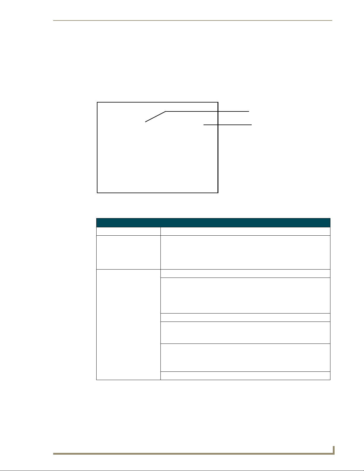
Firmware Pages and Descriptions
Press and hold the front panel CALIBRATE button to access the Calibration page.
Press the crosshairs to calibrate the panel and return to the last open firmware page.
System Connection Page
The System Connection page (FIG. 57) sets the DNS Address information with its corresponding IP
communication parameters, NetLinx Master communication settings, and reads the device number
assigned to the G4 device.
IP Settings section
Master Connection section
(NetLinx Master properties)
Master Connection features are not
saved until the panel is rebooted
Red fields are user-editable
Blue fields cycle through choices
Grey fields are read-only
FIG. 57 System Connection page (showing default values)
The elements of the System Connection page are described in the table below:
System Connection Page Elements
Back: Saves the changes and returns you to the previously active touch panel page.
Connection Status icon: This visual display of the connection status allows the user to have a current
IP Settings: Sets the IP communication values for the NXP-TPI/4 and contains:
DHCP/Static Sets the G4 device to either DHCP or Static communication modes.
IP Address Sets the IP Address assigned to the TPI/4.
Subnet Mask Sets a subnetwork address to the TPI/4.
Gateway Sets a gateway value to the TPI/4.
Host Name Sets the host name of the TPI/4.
update of the TPI/4’s connection status regardless of what page is currently
active.
• A Lock only appears on the icon if the TPI/4 has established a connection with
a currently secured target Master (requiring a username and password).
• DHCP (Dynamic Host Configuration Protocol) assigns IP Addresses from
client stations logging onto a TCP/IP network via a DHCP server.
• Static IP is a permanent IP Address that is assigned to a node in a TCP/IP
network.
• Subnetwork mask is the technique used by the IP protocol to filter messages
into a particular network segment (Subnet).
• Gateway is a computer that either performs protocol conversion between
different types of networks/applications or acts as a go-between two or more
networks that use the same protocols.
NXP-TPI/4 NetLinx Touch Panel Interface
75
Page 82

Firmware Pages and Descriptions
System Connection Page Elements (Cont.)
IP Settings (Cont.):
Primary DNS Sets the address of the primary DNS server being used by the TPI/4 for host
Secondary DNS Sets the secondary DNS value to the TPI/4.
Domain Sets the unique name on the Internet to the TPI/4 for DNS look-up.
Ethernet Mode Sets the speed of the Ethernet connection to the TPI/4.
MAC Address Displays a read-only field that is factory set by AMX for the built-in Ethernet
Master Connection: Sets the NetLinx Master communication values:
ICSNET/Ethernet Sets the NetLinx Master to communicate to the TPI/4 via either ICSNet or
Mode Cycles between the different connection modes (URL, Listen, and Auto)
System Number Allows you to enter a system number.
Master IP/URL Sets the Master IP or URL of the NetLinx Master. (ETHERNET Only)
Master Port Number Allows you to enter the port number used with the NetLinx Master.
Username/Password If the target Master has been previously secured, enter the alpha-numeric string
name lookups.
• DNS (Domain Name System) is software that lets users locate computers on
a local network or the Internet (TCP/IP network) by host and domain. The
DNS server maintains a database of host names for its’ domain and their
corresponding IP Addresses.
• The TPI/4 belongs to the DNS domain.
• Choices are: Auto, 10 Half Duplex, 10 Full Duplex, 100 Half Duplex, or
100 Full Duplex.
interface.
Ethernet. This is based on the cable connection from the rear.
• ICSNet is a CAT-5 cable (terminated in an RJ-45 connector) used to distribute
communications between the NetLinx Master and the TPI/4. ICSNet differs
from Ethernet in that ICSNet can provide power to any connected devices.
• Ethernet is a CAT-5 cable (10/100Base T terminated in an RJ-45 connector)
used to network computers together and is used in most LAN (local area
networks). This description is also used to refer to both wired and wireless
communication.
(ETHERNET Only)
• URL - In this mode, enter the IP/URL, Master Port Number, and
username/password (if used) on the Master.
- The System Number field is read-only because the TPI/4 obtains this
information from the communicating Master.
• Listen - In this mode, add the TPI/4 address into the URL List in NetLinx
Studio and set the connection mode to Listen. This mode allows the TPI/4 to
"listen" for the Master’s communication signals.
- The System Number and Master IP/URL fields are red-only.
• Auto - In this mode, enter the System Number and a username/password
(if applicable). This mode is used when both the TPI/4 and the NetLinx
Master are on the same Subnet and the Master has its UDP feature enabled.
- Master IP/URL field is read-only.
• Default value is 0 (zero). (ETHERNET Only)
• Default value is 1319. (ETHERNET Only)
(into each field) assigned to a pre-configured user profile on the Master.
This profile should have the pre-defined level of access/configuration rights.
76
Refer to the Step 2: Choosing a Master Connection Mode Setting section on page 37, Step 3:
Configuring the Ethernet Connection Type section on page 37, and Master Connection - Using
ICSNet section on page 35 for more detailed information on using the System Connection page.
NXP-TPI/4 NetLinx Touch Panel Interface
Page 83

Programming
You can program the touch panel, using the commands in this section, to perform a wide variety of
operations using Send_Commands and variable text commands. Refer to the NetLinx Programming
Language instruction manual for complete information.
Verify you are using the latest NetLinx Master firmware. Verify the NetLinx Studio
program being used is version 2.x or higher and TPD4 is version 2.6 or higher.
Button Assignments
Programming
• Button Channel Range: 1 - 4000 Button push and Feedback (per address port)
• Button Variable Text range: 1 - 4000 (per address port)
• Button States Range: 1 - 256
(0 = All states, for General buttons 1 = Off state and 2 = On state).
• Level Range: 1 - 600 (Default level value 0 - 255, can be set up to 1 - 65535)
• Address port Range: 1 - 100
Button assignments can only be adjusted in TPD4, not on the panels themselves.
You can program the TPI/4, using the commands described in this section, to perform a wide variety of
operations.
A device must first be defined in the NetLinx programming language with values for the Device:
Port: System (in all programming examples - Panel is used in place of these values and represents all
compatible G4 device).
Page Commands‘
These Page Commands are used in NetLinx Programming Language and are case insensitive.
Page Commands
@APG
Add a specific
popup page to a
specified popup
group.
Add the popup page to a group if it does not already exist. If the new popup is added to a
group which has a popup displayed on the current page along with the new pop-up, the
displayed popup will be hidden and the new popup will be displayed.
Syntax:
"'@APG-<popup page name>;<popup group name>'"
Var iable :
popup page name = 1 - 50 ASCII characters. Name of the popup page.
popup group name = 1 - 50 ASCII characters. Name of the popup group.
Example:
SEND_COMMAND Panel,"'@APG-Popup1;Group1'"
Adds the popup page ’Popup1’ to the popup group ’Group1’.
NXP-TPI/4 NetLinx Touch Panel Interface
77
Page 84

Programming
Page Commands (Cont.)
@CPG
Clear all popup
pages from
specified popup
group.
@DPG
Delete a specific
popup page from
specified popup
group if it exists.
@PDR
Set the popup
location reset flag.
@PHE
Set the hide effect
for the specified
popup page to the
named hide effect.
@PHP
Set the hide effect
position.
Syntax:
"'@CPG-<popup group>'"
Var iable :
popup group = 1 - 50 ASCII characters. Name of the popup group.
Example:
SEND_COMMAND Panel,"'@CPG-Group1'"
Clears all popup pages from the popup group ’Group1’.
Syntax:
"'@DPG-<popup page name>;<popup group name>'"
Var iable :
popup page name = 1 - 50 ASCII characters. Name of the popup page.
popup group name = 1 - 50 ASCII characters. Name of the popup group.
Example:
SEND_COMMAND Panel,"'@DPG-Popup1;Group1'"
Deletes the popup page ’Popup1’ from the popup group ’Group1’.
If the flag is set, the popup will return to its default location on show instead of its last drag
location.
Syntax:
"'@PDR-<popup page name>;<reset flag>'"
Var iable :
popup page name = 1 - 50 ASCII characters. Name of the page the popup is displayed
On.
reset flag = 1 = Enable reset flag
0 = Disable reset flag
Example:
SEND_COMMAND Panel,"'@PDR-Popup1'"
Popup1 will return to its default location when turned On.
Syntax:
"'@PHE-<popup page name>;<hide effect name>'"
Var iable :
popup page name = 1 - 50 ASCII characters. Name of the page the popup is displayed
On.
hide effect name = Refers to the popup effect names being used.
Example:
SEND_COMMAND Panel,"'@PHE-Popup1;Slide Left'"
Sets the Popup1 hide effect name to ’Slide Left’.
Only 1 coordinate is ever needed for an effect, however, the command will specify both.
This command sets the location at which the effect will end at.
Syntax:
"'@PHP-<popup page name>;<x coordinate>,<y coordinate>'"
Var iable :
popup page name = 1 - 50 ASCII characters. Name of the page the popup is displayed
On.
Example:
SEND_COMMAND Panel,"'@PHP-Popup1;75,0'"
Sets the Popup1 hide effect x-coordinate value to 75 and the y-coordinate value to 0.
78
NXP-TPI/4 NetLinx Touch Panel Interface
Page 85

Page Commands (Cont.)
@PHT
Set the hide effect
time for the
specified popup
page.
@PPA
Close all popups
on a specified
page.
@PPF
Deactivate a
specific popup
page on either a
specified page or
the current page.
@PPG
Toggle a
specific popup
page on either a
specified page or
the current page.
Syntax:
"'@PHT-<popup page name>;<hide effect time>'"
Var iable :
popup page name = 1 - 50 ASCII characters. Name of the page the popup is displayed
On.
hide effect time = Given in 1/10ths of a second.
Example:
SEND_COMMAND Panel,"'@PHT-Popup1;50'"
Sets the Popup1 hide effect time to 5 seconds.
If the page name is empty, the current page is used. Same as the ’Clear Page’ command
in TPDesign4.
Syntax:
"'@PPA-<page name>'"
Var iable :
page name = 1 - 50 ASCII characters. Name of the page the popup is displayed On.
Example:
SEND_COMMAND Panel,"'@PPA-Page1'"
Close all popups on Page1.
If the page name is empty, the current page is used (see example 2). If the popup page is
part of a group, the whole group is deactivated. This command works in the same way as
the ’Hide Popup’ command in TPDesign4.
Syntax:
"'@PPF-<popup page name>;<page name>'"
Var iable :
popup page name = 1 - 50 ASCII characters. Name of the popup page.
page name = 1 - 50 ASCII characters. Name of the page the popup is displayed On.
Example:
SEND_COMMAND Panel,"'@PPF-Popup1;Main'"
Deactivates the popup page ’Popup1’ on the Main page.
Example 2:
SEND_COMMAND Panel,"'@PPF-Popup1'"
Deactivates the popup page ’Popup1’ on the current page.
If the page name is empty, the current page is used (see example 2). Toggling refers to the
activating/deactivating (On/Off) of a popup page. This command works in the same way
as the ’Toggle Popup’ command in TPDesign4.
Syntax:
"'@PPG-<popup page name>;<page name>'"
Var iable :
popup page name = 1 - 50 ASCII characters. Name of the popup page.
page name = 1 - 50 ASCII characters. Name of the page the popup is displayed On.
Example:
SEND_COMMAND Panel,"'@PPG-Popup1;Main'"
Toggles the popup page ’Popup1’ on the ’Main’ page from one state to another (On/Off).
Example 2:
SEND_COMMAND Panel,"'@PPG-Popup1'"
Toggles the popup page ’Popup1’ on the current page from one state to another (On/Off).
Programming
NXP-TPI/4 NetLinx Touch Panel Interface
79
Page 86

Programming
Page Commands (Cont.)
@PPK
Kill a specific
popup page from
all pages.
@PPM
Set the modality
of a specific
popup page to
Modal or
NonModal.
@PPN
Activate a
specific popup
page to launch on
either a specified
page or the
current page.
Kill refers to the deactivating (Off) of a popup window from all pages. If the pop-up page is
part of a group, the whole group is deactivated. This command works in the same way as
the 'Clear Group' command in TPDesign 4.
Syntax:
"'@PPK-<popup page name>'"
Var iable :
popup page name = 1 - 50 ASCII characters. Name of the popup page.
Example:
SEND_COMMAND Panel,"'@PPK-Popup1'"
Kills the popup page ’Popup1’ on all pages.
A Modal popup page, when active, only allows you to use the buttons and features on that
popup page. All other buttons on the panel page are inactivated.
Syntax:
"'@PPM-<popup page name>;<mode>'"
Var iable :
popup page name = 1 - 50 ASCII characters. Name of the popup page.
mode = NONMODAL converts a previously Modal popup page to a NonModal.
MODAL converts a previously NonModal popup page to Modal.
modal = 1 and non-modal = 0
Example:
SEND_COMMAND Panel,"'@PPM-Popup1;Modal'"
Sets the popup page ’Popup1’ to Modal.
SEND_COMMAND Panel,"'@PPM-Popup1;1'"
Sets the popup page ’Popup1’ to Modal.
If the page name is empty, the current page is used (see example 2). If the popup page is
already on, do not re-draw it. This command works in the same way as the ’Show Popup’
command in TPDesign4.
Syntax:
"'@PPN-<popup page name>;<page name>'"
Var iable :
popup page name = 1 - 50 ASCII characters. Name of the popup page.
page name = 1 - 50 ASCII characters. Name of the page the popup is displayed On.
Example:
SEND_COMMAND Panel,"'@PPN-Popup1;Main'"
Activates ’Popup1’ on the ’Main’ page.
Example 2:
SEND_COMMAND Panel,"'@PPN-Popup1'"
Activates the popup page ’Popup1’ on the current page.
80
NXP-TPI/4 NetLinx Touch Panel Interface
Page 87

Page Commands (Cont.)
@PPT
Set a specific
popup page to
timeout within a
specified time.
@PPX
Close all
popups on all
pages.
@PSE
Set the show
effect for the
specified popup
page to the
named show
effect.
@PSP
Set the show
effect position.
@PST
Set the show
effect time for the
specified popup
page.
If timeout is empty, popup page will clear the timeout.
Syntax:
"'@PPT-<popup page name>;<timeout>'"
Var iable :
popup page name = 1 - 50 ASCII characters. Name of the popup page.
timeout = Timeout duration in 1/10ths of a second.
Example:
SEND_COMMAND Panel,"'@PPT-Popup1;30'"
Sets the popup page ’Popup1’ to timeout within 3 seconds.
Same as a 'Clear All' command in TPDesign 4.
Syntax:
"'@PPX'"
Example:
SEND_COMMAND Panel,"'@PPX'"
Close all popups on all pages.
Only 1 coordinate is ever needed for an effect, however the command will specify both.
This command sets the location at which the effect will begin at.
Syntax:
"'@PSE-<popup page name>;<show effect name>'"
Var iable :
popup page name = 1 - 50 ASCII characters. Name of the page the popup is displayed
On.
show effect name = Refers to the popup effect name being used.
Example:
SEND_COMMAND Panel,"'@PSE-Popup1;Slide from Left'"
Sets the Popup1 show effect name to ’Slide from Left’.
Only 1 coordinate is ever needed for an effect; however, the command will specify both.
This command sets the location at which the effect will begin at.
Syntax:
"'@PSP-<popup page name>;<x coordinate>,<y coordinate>'"
Var iable :
popup page name = 1 - 50 ASCII characters. Name of the page the popup is displayed
On.
Example:
SEND_COMMAND Panel,"'@PSP-Popup1;100,0'"
Sets the Popup1 show effect x-coordinate value to 100 and the y-coordinate value to 0.
Syntax:
"'@PST-<popup page name>;<show effect time>'"
Var iable :
popup page name = 1 - 50 ASCII characters. Name of the page the popup is displayed
On.
show effect time = Given in 1/10ths of a second.
Example:
SEND_COMMAND Panel,"'@PST-Popup1;50'"
Sets the Popup1 show effect time to 5 seconds.
Programming
NXP-TPI/4 NetLinx Touch Panel Interface
81
Page 88

Programming
Page Commands (Cont.)
PAG E
Flip to a specified
page.
PPOF
Deactivate a
specific popup
page on either a
specified page or
the current page.
PPOG
Toggle a
specific popup
page on either a
specified page or
the current page.
Flips to a page with a specified page name. If the page is currently active, it will not redraw
the page.
Syntax:
"'PAGE-<page name>'"
Var iable :
page name = 1 - 50 ASCII characters. Name of the page the popup is displayed On.
Example:
SEND_COMMAND Panel,"'PAGE-Page1'"
Flips to page1.
If the page name is empty, the current page is used (see example 2). If the popup page is
part of a group, the whole group is deactivated. This command works in the same way as
the ’Hide Popup’ command in TPDesign4.
Syntax:
"'PPOF-<popup page name>;<page name>'"
Var iable :
popup page name = 1 - 50 ASCII characters. Name of the popup page.
page name = 1 - 50 ASCII characters. Name of the page the popup is displayed On.
Example:
SEND_COMMAND Panel,"'PPOF-Popup1;Main'"
Deactivates the popup page ’Popup1’ on the Main page.
Example 2:
SEND_COMMAND Panel,"'PPOF-Popup1'"
Deactivates the popup page ’Popup1’ on the current page.
If the page name is empty, the current page is used (see example 2). Toggling refers to the
activating/deactivating (On/Off) of a popup page. This command works in the same way
as the ’Toggle Popup’ command in TPDesign4.
Syntax:
"'PPOG-<popup page name>;<page name>'"
Var iable :
popup page name = 1 - 50 ASCII characters. Name of the popup page.
page name = 1 - 50 ASCII characters. Name of the page the popup is displayed On.
Example:
SEND_COMMAND Panel,"'PPOG-Popup1;Main'"
Toggles the popup page ’Popup1’ on the Main page from one state to another (On/Off).
Example 2:
SEND_COMMAND Panel,"'PPOG-Popup1'"
Toggles the popup page ’Popup1’ on the current page from one state to another (On/Off).
82
NXP-TPI/4 NetLinx Touch Panel Interface
Page 89
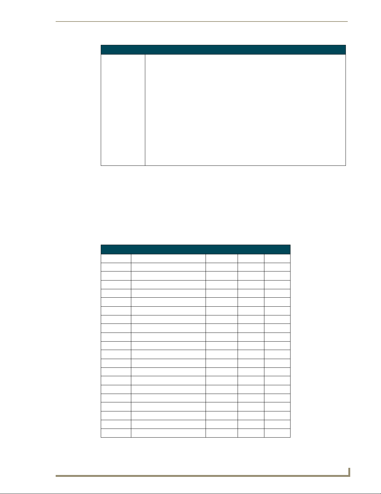
Programming
Page Commands (Cont.)
PPON
Activate a
specific popup
page to launch on
either a specified
page or the
current page.
If the page name is empty, the current page is used (see example 2). If the popup page is
already On, do not re-draw it. This command works in the same way as the ’Show Popup’
command in TPDesign4.
Syntax:
"'PPON-<popup page name>;<page name>'"
Var iable :
popup page name = 1 - 50 ASCII characters. Name of the popup page.
page name = 1 - 50 ASCII characters. Name of the page the popup is displayed On.
Example:
SEND_COMMAND Panel,"'PPON-Popup1; Main'"
Activates the popup page ’Popup1’ on the Main page.
Example 2:
SEND_COMMAND Panel,"'PPON-Popup1'"
Activates the popup page ’Popup1’ on the current page.
Programming Numbers
The following information provides the programming numbers for colors, fonts, and borders.
Colors can be used to set the colors on buttons, sliders, and pages. The lowest color number represents
the lightest color-specific display; the highest number represents the darkest display. For example, 0
represents light red, and 5 is dark red. The following table lists the RGB color values and names for
standard 88 colors.
RGB triplets and names for basic 88 colors
RGB Values for all 88 Basic Colors
Index No. Name Red Green Blue
00 Very Light Red 255 0 0
01 Light Red 223 0 0
02 Red 191 0 0
03 Medium Red 159 0 0
04 Dark Red 127 0 0
05 Very Dark Red 95 0 0
06 Very Light Orange 255 128 0
07 Light Orange 223 112 0
08 Orange 191 96 0
09 Medium Orange 159 80 0
10 Dark Orange 127 64 0
11 Very Dark Orange 95 48 0
12 Very Light Yellow 255 255 0
13 Light Yellow 223 223 0
14 Yellow 191 191 0
15 Medium Yellow 159 159 0
16 Dark Yellow 127 127 0
17 Very Dark Yellow 95 95 0
18 Very Light Lime 128 255 0
19 Light Lime 112 223 0
NXP-TPI/4 NetLinx Touch Panel Interface
83
Page 90

Programming
RGB Values for all 88 Basic Colors (Cont.)
Index No. Name Red Green Blue
20 Lime 96 191 0
21 Medium Lime 80 159 0
22 Dark Lime 64 127 0
23 Very Dark Lime 48 95 0
24 Very Light Green 0 255 0
25 Light Green 0 223 0
26 Green 0 191 0
27 Medium Green 0 159 0
28 Dark Green 0 127 0
29 Very Dark Green 0 95 0
30 Very Light Mint 0 255 128
31 Light Mint 0 223 112
32 Mint 0 191 96
33 Medium Mint 0 159 80
34 Dark Mint 0 127 64
35 Very Dark Mint 0 95 48
36 Very Light Cyan 0 255 255
37 Light Cyan 0 223 223
38 Cyan 0 191 191
39 Medium Cyan 0 159 159
40 Dark Cyan 0 127 127
41 Very Dark Cyan 0 95 95
42 Very Light Aqua 0 128 255
43 Light Aqua 0 112 223
44 Aqua 0 96 191
45 Medium Aqua 0 80 159
46 Dark Aqua 0 64 127
47 Very Dark Aqua 0 48 95
48 Very Light Blue 0 0 255
49 Light Blue 0 0 223
50 Blue 0 0 191
51 Medium Blue 0 0 159
52 Dark Blue 0 0 127
53 Very Dark Blue 0 0 95
54 Very Light Purple 128 0 255
55 Light Purple 112 0 223
56 Purple 96 0 191
57 Medium Purple 80 0 159
58 Dark Purple 64 0 127
59 Very Dark Purple 48 0 95
60 Very Light Magenta 255 0 255
61 Light Magenta 223 0 223
62 Magenta 191 0 191
63 Medium Magenta 159 0 159
84
NXP-TPI/4 NetLinx Touch Panel Interface
Page 91
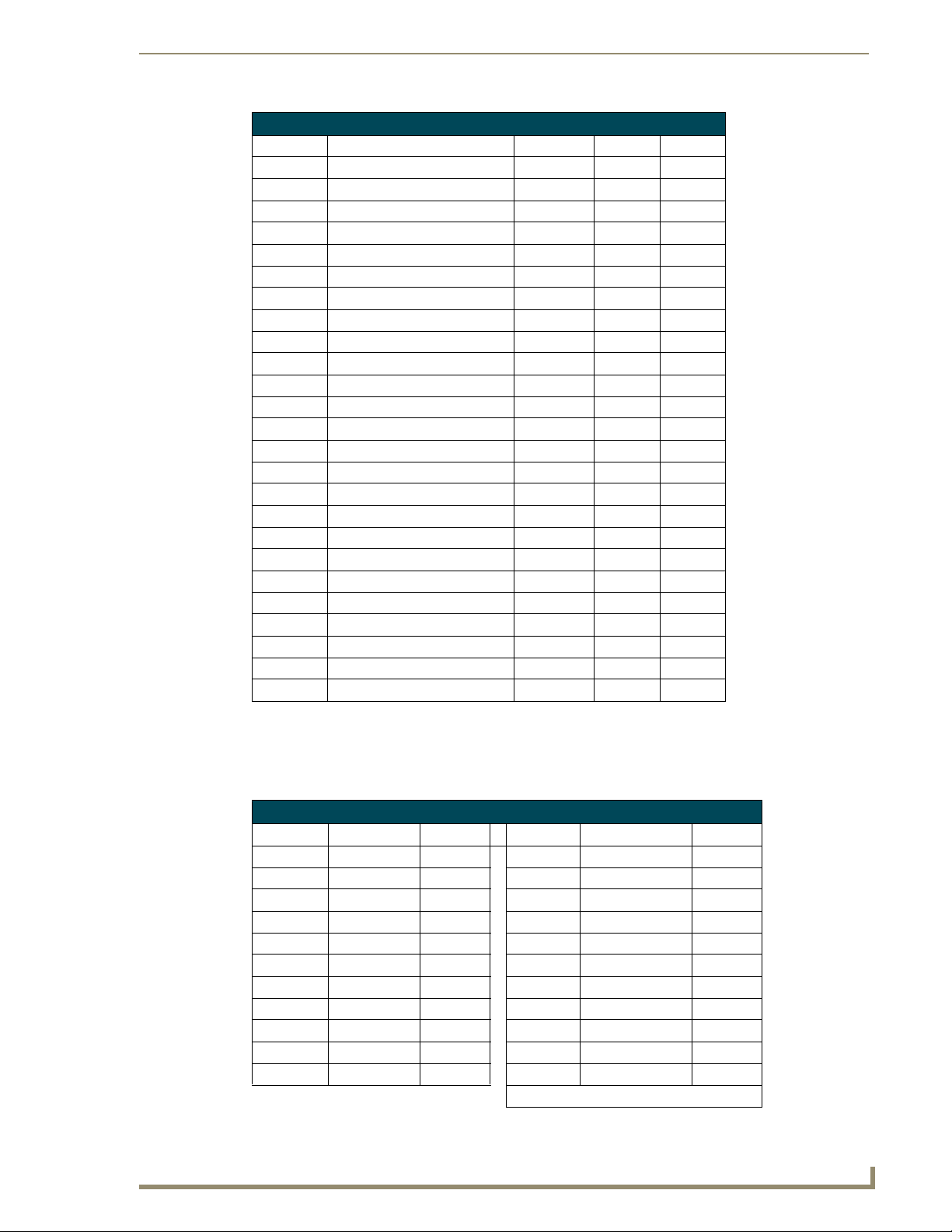
RGB Values for all 88 Basic Colors (Cont.)
Index No. Name Red Green Blue
64 Dark Magenta 127 0 127
65 Very Dark Magenta 95 0 95
66 Very Light Pink 255 0 128
67 Light Pink 223 0 112
68 Pink 191 0 96
69 Medium Pink 159 0 80
70 Dark Pink 127 0 64
71 Very Dark Pink 95 0 48
72 White 255 255 255
73 Grey1 238 238 238
74 Grey3 204 204 204
75 Grey5 170 170 170
76 Grey7 136 136 136
77 Grey9 102 102 102
78 Grey4 187 187 187
79 Grey6 153 153 153
80 Grey8 119 119 119
81 Grey10 85 85 85
82 Grey12 51 51 51
83 Grey13 34 34 34
84 Grey2 221 221 221
85 Grey11 68 68 68
86 Grey14 17 17 17
87 Black 0 0 0
255 TRANSPARENT 99 53 99
Programming
Font styles and ID numbers
Font styles can be used to program the text fonts on buttons, sliders, and pages. The following chart
shows the default font type and their respective ID numbers generated by TPDesign4.
Default Font Styles and ID Numbers
Font ID # Font type Size Font ID # Font type Size
1 Courier New 9 19 Arial 9
2 Courier New 12 20 Arial 10
3 Courier New 18 21 Arial 12
4 Courier New 26 22 Arial 14
5 Courier New 32 23 Arial 16
6 Courier New 18 24 Arial 18
7 Courier New 26 25 Arial 20
8 Courier New 34 26 Arial 24
9 AMX Bold 14 27 Arial 36
10 AMX Bold 20 28 Arial Bold 10
11 AMX Bold 36 29 Arial Bold 8
NXP-TPI/4 NetLinx Touch Panel Interface
32 - Variable Fonts start at 32.
85
Page 92

Programming
You must import fonts into a TPDesign4 project file. The font ID numbers are
assigned by TPDesign4. These values are also listed in the
Generate Programmer’s Report.
Border styles and Programming numbers
Border styles can be used to program borders on buttons, sliders, and popup pages.
Border Styles and Programming Numbers
No. Border styles No. Border styles
0-1 No border 10-11 Picture frame
2 Single line 12 Double line
3 Double line 20 Bevel-S
4 Quad line 21 Bevel-M
5-6 Circle 15 22-23 Circle 15
7 Single line 24-27 Neon inactive-S
8 Double line 40-41 Diamond 55
9 Quad line
The TPDesign4 design program has pre-set border styles that are user selectable. You cannot use the
following number values for programming purposes when changing border styles. TPD4 border styles
can ONLY be changed by using the name.
TPD4 Border Styles by Name
No. Border styles No. Border styles
1 None 16 Circle 95
2 AMX Elite -L 17 Circle 105
3 AMX Elite -M 18 Circle 115
4 AMX Elite -S 19 Circle 125
5 Bevel -L 20 Circle 135
6 Bevel -M 21 Circle 145
7 Bevel -S 22 Circle 155
8 Circle 15 23 Circle 165
9 Circle 25 24 Circle 175
10 Circle 35 25 Circle 185
11 Circle 45 26 Circle 195
12 Circle 55 27 Cursor Bottom
13 Circle 65 28 Cursor Bottom with Hole
14 Circle 75 29 Cursor Top
15 Circle 85 30 Cursor Top with Hole
86
NXP-TPI/4 NetLinx Touch Panel Interface
Page 93

TPD4 Border Styles by Name (Cont.)
No. Border styles No. Border styles
31 Cursor Left 60 Glow-L
32 Cursor Left with Hole 61 Glow-S
33 Cursor Right 62 Help Down
34 Cursor Right with Hole 63 Neon Active -L
35 Custom Frame 64 Neon Active -S
36 Diamond 15 65 Neon Inactive -L
37 Diamond 25 66 Neon Inactive -S
38 Diamond 35 67 Oval H 60x30
39 Diamond 45 68 Oval H 100x50
40 Diamond 55 69 Oval H 150x75
41 Diamond 65 70 Oval H 200x100
42 Diamond 75 71 Oval V 30x60
28 Cursor Bottom with Hole 72 Oval V 50x100
29 Cursor Top 73 Oval V 75x150
30 Cursor Top with Hole 74 Oval V 100x200
31 Cursor Left 75 Picture Frame
32 Cursor Left with Hole 76 Quad Line
33 Cursor Right 77 Single Line
34 Cursor Right with Hole 78 Windows Style Popup
35 Custom Frame 79 Windows Style Popup (Status Bar)
36 Diamond 15 80 Menu Bottom Rounded 15
37 Diamond 25 81 Menu Bottom Rounded 25
38 Diamond 35 82 Menu Bottom Rounded 35
39 Diamond 45 83 Menu Bottom Rounded 45
40 Diamond 55 84 Menu Bottom Rounded 55
41 Diamond 65 85 Menu Bottom Rounded 65
42 Diamond 75 86 Menu Bottom Rounded 75
43 Diamond 85 87 Menu Bottom Rounded 85
44 Diamond 95 88 Menu Bottom Rounded 95
45 Diamond 105 89 Menu Bottom Rounded 105
46 Diamond 115 90 Menu Bottom Rounded 115
47 Diamond 125 91 Menu Bottom Rounded 125
48 Diamond 135 92 Menu Bottom Rounded 135
49 Diamond 145 93 Menu Bottom Rounded 145
50 Diamond 155 94 Menu Bottom Rounded 155
51 Diamond 165 95 Menu Bottom Rounded 165
52 Diamond 175 96 Menu Bottom Rounded 175
53 Diamond 185 97 Menu Bottom Rounded 185
54 Diamond 195 98 Menu Bottom Rounded 195
55 Double Bevel -L 99 Menu Top Rounded 15
56 Double Bevel -M 100 Menu Top Rounded 25
57 Double Bevel -S 101 Menu Top Rounded 35
58 Double Line 102 Menu Top Rounded 45
59 Fuzzy 103 Menu Top Rounded 55
Programming
NXP-TPI/4 NetLinx Touch Panel Interface
87
Page 94

Programming
TPD4 Border Styles by Name (Cont.)
No. Border styles No. Border styles
104 Menu Top Rounded 65 134 Menu Right Rounded 175
105 Menu Top Rounded 75 135 Menu Right Rounded 185
106 Menu Top Rounded 85 136 Menu Right Rounded 195
107 Menu Top Rounded 95 137 Menu Left Rounded 15
108 Menu Top Rounded 105 138 Menu Left Rounded 25
109 Menu Top Rounded 115 139 Menu Left Rounded 35
110 Menu Top Rounded 125 140 Menu Left Rounded 45
111 Menu Top Rounded 135 141 Menu Left Rounded 55
112 Menu Top Rounded 145 142 Menu Left Rounded 65
113 Menu Top Rounded 155 143 Menu Left Rounded 75
114 Menu Top Rounded 165 144 Menu Left Rounded 85
115 Menu Top Rounded 175 137 Menu Left Rounded 15
116 Menu Top Rounded 185 138 Menu Left Rounded 25
117 Menu Top Rounded 195 139 Menu Left Rounded 35
118 Menu Right Rounded 15 140 Menu Left Rounded 45
119 Menu Right Rounded 25 141 Menu Left Rounded 55
120 Menu Right Rounded 35 142 Menu Left Rounded 65
121 Menu Right Rounded 45 143 Menu Left Rounded 75
122 Menu Right Rounded 55 144 Menu Left Rounded 85
123 Menu Right Rounded 65 145 Menu Left Rounded 95
124 Menu Right Rounded 75 146 Menu Left Rounded 105
125 Menu Right Rounded 85 147 Menu Left Rounded 115
126 Menu Right Rounded 95 148 Menu Left Rounded 125
127 Menu Right Rounded 105 149 Menu Left Rounded 135
128 Menu Right Rounded 115 150 Menu Left Rounded 145
129 Menu Right Rounded 125 151 Menu Left Rounded 155
130 Menu Right Rounded 135 152 Menu Left Rounded 165
131 Menu Right Rounded 145 153 Menu Left Rounded 175
132 Menu Right Rounded 155 154 Menu Left Rounded 185
133 Menu Right Rounded 165 155 Menu Left Rounded 195
88
"^" Button Commands
These Button Commands are used in NetLinx Studio and are case insensitive.
All commands that begin with "^" have the capability of assigning a variable text address range and
button state range. A device must first be defined in the NetLinx programming language with values
for the Device: Port : System (in all programming examples - Panel is used in place of these values).
Variable text ranges allow you to target 1 or more var txt channels in a single command.
Button State ranges allow you to target 1 or more states of a variable text button with a single
command.
"." Character is used for the 'through' notation, also the "&" character is used for the 'And'
notation.
NXP-TPI/4 NetLinx Touch Panel Interface
Page 95

"^" Button Commands
^ANI
Run a button
animation
(in 1/10 second).
^APF
Add page flip
action to a button
if it does not
already exist.
^BAT
Append
non-unicode text.
^BAU
Append
unicode text.
Syntax:
"'^ANI-<vt addr range>,<start state>,<end state>,<time>'"
Var iable :
variable text address range = 1 - 4000.
start state = Beginning of button state (0= current state).
end state = End of button state.
time = in 1/10 second intervals.
Example:
SEND_COMMAND Panel,"'^ANI-500,1,25,100'"
Runs a button animation at text range 500 from state 1 to state 25 for 10 second.
Syntax:
"'^APF-<vt addr range>,<page flip action>,<page name>'"
Var iable :
variable text address range = 1 - 4000.
page flip action= Stan[dardPage] - Flip to standard page
Prev[iousPage] - Flip to previous page
Show[Popup] - Show Popup page
Hide[Popup] - Hide Popup page
Togg [lePopup] - Toggle popup state
ClearG[roup] - Clear popup page group from all pages
ClearP[age] - Clear all popup pages from a page with the
specified page name
ClearA[ll] - Clear all popup pages from all pages
page name = 1 - 50 ASCII characters.
Example:
SEND COMMAND Panel,"'^APF-400,Stan,Main Page'"
Assigns a button to a standard page flip with page name 'Main Page'.
Syntax:
"'^BAT-<vt addr range>,<button states range>,<new text>'"
Var iable :
variable text address range = 1 - 4000.
button states range = 1 - 256 for multi-state buttons (0 = All states, for General buttons
1 = Off state and 2 = On state).
new text = 1 - 50 ASCII characters.
Example:
SEND_COMMAND Panel,"'^BAT-520,1,Enter City'"
Appends the text 'Enter City' to the button’s OFF state.
Same format as ^UNI.
Syntax:
"'^BAU-<vt addr range>,<button states range>,<unicode text>'"
Var iable :
variable text address range = 1 - 4000.
button states range = 1 - 256 for multi-state buttons (0 = All states, for General buttons
1 = Off state and 2 = On state).
unicode text = 1 - 50 ASCII characters. Unicode characters must be entered in Hex
format.
Example:
SEND_COMMAND Panel,"'^BAU-520,1,00770062'"
Appends Unicode text '00770062' to the button’s OFF state.
Programming
NXP-TPI/4 NetLinx Touch Panel Interface
89
Page 96

Programming
"^" Button Commands (Cont.)
^BCB
Set the border
color to the
specified color.
^BCF
Set the fill color to
the specified
color.
Only if the specified border color is not the same as the current color.
Note: Color can be assigned by color name (without spaces), number or R,G,B value
(RRGGBB or RRGGBBAA).
Syntax:
"'^BCB-<vt addr range>,<button states range>,<color value>'"
Var iable :
variable text address range = 1 - 4000.
button states range = 1 - 256 for multi-state buttons (0 = All states, for General buttons
1 = Off state and 2 = On state).
color value = Refer to theRGB Values for all 88 Basic Colors table on page 83 for more
information.
Example:
SEND_COMMAND Panel,"'^BCB-500.504&510,1,12'"
Sets the Off state border color to 12 (Yellow). Colors can be set by Color Numbers, Color
name, R,G,B,alpha colors (RRGGBBAA) and R, G & B colors values (RRGGBB).
Refer to theRGB Values for all 88 Basic Colors table on page 83.
Only if the specified fill color is not the same as the current color.
Note: Color can be assigned by color name (without spaces), number or R,G,B value
(RRGGBB or RRGGBBAA).
Syntax:
"'^BCF-<vt addr range>,<button states range>,<color value>'"
Var iable :
variable text address range = 1 - 4000.
button states range = 1 - 256 for multi-state buttons (0 = All states, for General buttons
1 = Off state and 2 = On state).
color value = Refer to theRGB Values for all 88 Basic Colors table on page 83 for more
information.
Example:
SEND_COMMAND Panel,"'^BCF-500.504&510.515,1,12'"
SEND_COMMAND Panel,"'^BCF-500.504&510.515,1,Yellow'"
SEND_COMMAND Panel,"'^BCF-500.504&510.515,1,#F4EC0A63''"
SEND_COMMAND Panel,"'^BCF-500.504&510.515,1,#F4EC0A'"
Sets the Off state fill color by color number. Colors can be set by Color Numbers, Color
name, R,G,B,alpha colors (RRGGBBAA) and R, G & B colors values (RRGGBB).
90
NXP-TPI/4 NetLinx Touch Panel Interface
Page 97

"^" Button Commands (Cont.)
^BCT
Set the text color
to the specified
color.
^BDO
Set the button
draw order.
^BFB
Set the feedback
type of the button.
Only if the specified text color is not the same as the current color.
Note: Color can be assigned by color name (without spaces), number or R,G,B value
(RRGGBB or RRGGBBAA).
Syntax:
"'^BCT-<vt addr range>,<button states range>,<color value>'"
Var iable :
variable text address range = 1 - 4000.
button states range = 1 - 256 for multi-state buttons (0 = All states, for General buttons
1 = Off state and 2 = On state).
color value = Refer to theRGB Values for all 88 Basic Colors table on page 83 for more
information.
Example:
SEND_COMMAND Panel,"'^BCT-500.504&510,1,12'"
Sets the Off state border color to 12 (Yellow). Colors can be set by Color Numbers, Color
name, R,G,B,alpha colors (RRGGBBAA) and R, G & B colors values (RRGGBB).
Determines what order each layer of the button is drawn.
Syntax:
"'^BDO-<vt addr range>,<button states range>,<1-5><1-5><1-5><15><1-5>'"
Var iable :
variable text address range = 1 - 4000.
button states range = 1 - 256 for multi-state buttons (0 = All states, for General buttons
1 = Off state and 2 = On state).
layer assignments = Fill Layer = 1
Image Layer = 2
Icon Layer = 3
Text Layer = 4
Border Layer = 5
Note: The layer assignments are from bottom to top. The default draw order is 12345.
Example:
SEND_COMMAND Panel,"'^BDO-530,1&2,51432'"
Sets the button’s variable text 530 ON/OFF state draw order (from bottom to top) to
Border, Fill, Text, Icon, and Image.
Example 2:
SEND_COMMAND Panel,"'^BDO-1,0,12345'"
Sets all states of a button back to its default drawing order.
ONLY works on General-type buttons.
Syntax:
"'^BFB-<vt addr range>,<feedback type>'"
Var iable :
variable text address range = 1 - 4000.
feedback type = (None, Channel, Invert, On (Always on), Momentary, and Blink).
Example:
SEND_COMMAND Panel,"'^BFB-500,Momentary'"
Sets the Feedback type of the button to 'Momentary'.
Programming
NXP-TPI/4 NetLinx Touch Panel Interface
91
Page 98

Programming
"^" Button Commands (Cont.)
^BIM
Set the input
mask for the
specified address.
^BLN
Set the number of
lines removed
equally from the
top and bottom of
a composite video
signal.
Syntax:
"'^BIM-<vt addr range>,<input mask>'"
Var iable :
variable text address range = 1 - 4000.
input mask = Refer to theText Area Input Masking section on page 135 for character
types.
Example:
SEND_COMMAND Panel,"'^BIM-500,AAAAAAAAAA'"
Sets the input mask to ten ’A’ characters, that are required, to either a letter or digit
(entry is required).
The maximum number of lines to remove is 240. A value of 0 will display the incoming
video signal unaffected. This command is used to scale non 4x3 video images into non
4x3 video buttons.
Syntax:
"'^BLN-<vt addr range>,<button states range>,<number of lines>'"
Var iable :
variable text address range = 1 - 4000.
button states range = 1 - 256 for multi-state buttons (0 = All states, for General buttons
1 = Off state and 2 = On state).
number of lines = 0 - 240.
Example:
SEND_COMMAND Panel,"'^BLN-500,55'"
Equally removes 55 lines from the top and 55 lines from the bottom of the video button.
92
NXP-TPI/4 NetLinx Touch Panel Interface
Page 99

"^" Button Commands (Cont.)
^BMC
Button copy
command.
Copy attributes of
the source button
to all the
destination
buttons.
Note that the source is a single button state. Each state must be copied as a separate
command. The <codes> section represents what attributes will be copied. All codes are
2 char pairs that can be separated by comma, space, percent or just ran together.
Syntax:
"'^BMC-<vt addr range>,<button states range>,<source
port>,<source address>,<source state>,<codes>'"
Var iable :
variable text address range = 1 - 4000.
button states range = 1 - 256 for multi-state buttons (0 = All states, for General buttons
1 = Off state and 2 = On state).
source port = 1 - 100
source address = 1 - 4000
source state = 1 - 256
codes: BM - Picture/Bitmap
BR - Border
CB - Border Color
CF - Fill Color
CT - Text Color
EC - Text effect color
EF - Text effect
FT - Font
IC - Icon
JB - Bitmap alignment
JI - Icon alignment
JT - Text alignment
LN - Lines of video removed
OP - Opacity
SO - Button Sound
TX - Text
VI - Video slot ID
WW - Word wrap on/off
Example:
SEND_COMMAND Panel,"'^BMC-425,1,1,500,1,BR'"
or
SEND_COMMAND Panel,"'^BMC-425,1,1,500,1,%BR'"
Copies the OFF state border of button with a variable text address of 500 onto the OFF
state border of button with a variable text address of 425.
Example 2:
SEND_COMMAND Panel,"'^BMC-150,1,1,315,1,%BR%FT%TX%BM%IC%CF%CT'"
Copies the OFF state border, font, Text, bitmap, icon, fill color and text color of the button
with a variable text address of 315 onto the OFF state border, font, Text, bitmap, icon, fill
color and text color of the button with a variable text address of 150.
Programming
NXP-TPI/4 NetLinx Touch Panel Interface
93
Page 100

Programming
"^" Button Commands (Cont.)
^BMF
Set any/all button
parameters by
sending
embedded codes
and data.
Syntax:
"'^BMF-<vt addr range>,<button states range>,<data>'"
Var iable s:
variable text address char array = 1 - 4000.
button states range = 1 - 256 for multi-state buttons (0 = All states, for General buttons
1 = Off state and 2 = On state).
level range = 1 - 600 (level value is 1 - 65535).
data:
’%B<border style>’ = Set the border style name. See theBorder Styles and Programming
Numbers table on page 86.
’%B’,<border 0-27,40,41> = Set the borer style number. See the Border Styles and
Programming Numbers table on page 86.
’%DO<1-5><1-5><1-5><1-5><1-5> = Set the draw order. Listed from bottom to top.
Refer to the ^BDO command on page 91 for more information.
’%F’,<font 1-8,10,11,20-29,32-xx> = Set the font. See theDefault Font Styles and ID
Numbers table on page 85.
’%F<font 01-08,10,11,20-29,32-xx>’ = Set the font. See theDefault Font Styles and ID
Numbers table on page 85.
’%MI<mask image>’ = Set the mask image. Refer to the ^BMI command on page 96 for
more information.
’%T<text >’ = Set the text using ASCII characters (empty is clear).
’%P<bitmap>’ = Set the picture/bitmap filename (empty is clear).
’%I’,<icon 1-9900, 0-clear> = Set the icon using values of 1 - 9900 (icon numbers are
assigned in the TPDesign4 Resource Manager tab - Slots section).
’%I<icon 01-9900, 0-clear>’ = Set the icon using values of 01 - 9900 (icon numbers are
assigned in the TPDesign4 Resource Manager tab - Slots section).
’%J’,<alignment of text 1-9> = As shown the following telephone keypad alignment chart:
0
1
2
4
5
7
8
3
6
9
Zero can be used for an absolute position
’%JT<alignment of text 0-9>’ = As shown the above telephone keypad alignment chart,
BUT the 0 (zero) is absolute and followed by ’,<left>,<top>’
’%JB<alignment of bitmap/picture 0-9>’ = As shown the above telephone keypad
alignment chart BUT the 0 (zero) is absolute and followed by ’,<left>,<top>’
’%JI<alignment of icon 0-9>’ = As shown the above telephone keypad alignment chart,
BUT the 0 (zero) is absolute and followed by ’,<left>,<top>’
94
NXP-TPI/4 NetLinx Touch Panel Interface
 Loading...