

Page 1
Operation/Reference Guide
AMX TDS
Television Distribution System
ClearQAM / ATSC (High Definition)
Terrestrial/Satellite (Standard Definition)
Television Distribution System
Last Revised: 11/04/2011
Page 2

AMX Limited Warranty and Disclaimer
This Limited Warranty and Disclaimer extends only to products purchased directly from AMX or an AMX Authorized Partner which
include AMX Dealers, Distributors, VIP’s or other AMX authorized entity.
AMX warrants its products to be free of defects in material and workmanship under normal use for three (3) years from the date of
purchase, with the following exceptions:
• Electroluminescent and LCD Control Panels are warranted for three (3) years, except for the display and touch overlay components are warranted for a period of one (1) year.
• Disk drive mechanisms, pan/tilt heads, power supplies, and MX Series products are warranted for a period of one (1) year.
• AMX lighting products are guaranteed to switch on and off any load that is properly connected to our lighting products, as long
as the AMX lighting products are under warranty. AMX also guarantees the control of dimmable loads that are properly connected to our lighting products. The dimming performance or quality there of is not guaranteed, impart due to the random combinations of dimmers, lamps and ballasts or transformers.
• AMX software is warranted for a period of ninety (90) days.
• Batteries and incandescent lamps are not covered under the warranty.
• AMX AutoPatch Epica, Modula, Modula Series4, Modula CatPro Series and 8Y-3000 product models will be free of defects in
materials and manufacture at the time of sale and will remain in good working order for a period of three (3) years following the
date of the original sales invoice from AMX. The three-year warranty period will be extended to the life of the product (Limited
Lifetime Warranty) if the warranty card is filled out by the dealer and/or end user and returned to AMX so that AMX receives it
within thirty (30) days of the installation of equipment but no later than six (6) months from original AMX sales invoice date. The
life of the product extends until five (5) years after AMX ceases manufacturing the product model. The Limited Lifetime Warranty
applies to products in their original installation only. If a product is moved to a different installation, the Limited Lifetime Warranty
will no longer apply, and the product warranty will instead be the three (3) year Limited Warranty.
All products returned to AMX require a Return Material Authorization (RMA) number. The RMA number is obtained from the AMX
RMA Department. The RMA number must be clearly marked on the outside of each box. The RMA is valid for a 30-day period. After
the 30-day period the RMA will be cancelled. Any shipments received not consistent with the RMA, or after the RMA is cancelled, will
be refused. AMX is not responsible for products returned without a valid RMA number.
AMX is not liable for any damages caused by its products or for the failure of its products to perform. This includes any lost profits, lost
savings, incidental damages, or consequential damages. AMX is not liable for any claim made by a third party or by an AMX Authorized Partner for a third party.
This Limited Warranty does not apply to (a) any AMX product that has been modified, altered or repaired by an unauthorized agent or
improperly transported, stored, installed, used, or maintained; (b) damage caused by acts of nature, including flood, erosion, or earthquake; (c) damage caused by a sustained low or high voltage situation or by a low or high voltage disturbance, including brownouts,
sags, spikes, or power outages; or (d) damage caused by war, vandalism, theft, depletion, or obsolescence.
This limitation of liability applies whether damages are sought, or a claim is made, under this warranty or as a tort claim (including
negligence and strict product liability), a contract claim, or any other claim. This limitation of liability cannot be waived or amended by
any person. This limitation of liability will be effective even if AMX or an authorized representative of AMX has been advised of the
possibility of any such damages. This limitation of liability, however, will not apply to claims for personal injury.
Some states do not allow a limitation of how long an implied warranty last. Some states do not allow the limitation or exclusion of incidental or consequential damages for consumer products. In such states, the limitation or exclusion of the Limited Warranty may not
apply. This Limited Warranty gives the owner specific legal rights. The owner may also have other rights that vary from state to state.
The owner is advised to consult applicable state laws for full determination of rights.
EXCEPT AS EXPRESSLY SET FORTH IN THIS WARRANTY, AMX MAKES NO OTHER WARRANTIES, EXPRESSED OR
IMPLIED, INCLUDING ANY IMPLIED WARRANTIES OF MERCHANTABILITY OR FITNESS FOR A PARTICULAR PURPOSE. AMX
EXPRESSLY DISCLAIMS ALL WARRANTIES NOT STATED IN THIS LIMITED WARRANTY. ANY IMPLIED WARRANTIES THAT
MAY BE IMPOSED BY LAW ARE LIMITED TO THE TERMS OF THIS LIMITED WARRANTY. EXCEPT AS OTHERWISE LIMITED
BY APPLICABLE LAW, AMX RESERVES THE RIGHT TO MODIFY OR DISCONTINUE DESIGNS, SPECIFICATIONS, WARRANTIES, PRICES, AND POLICIES WITHOUT NOTICE.
Page 3

Table of Contents
i
AMX TDS (Television Delivery System)
Table of Contents
AMX Television Distribution System (TDS) .........................................................1
Overview .................................................................................................................. 1
Network Considerations.................................................................................................. 1
System Diagram - TDS Distribution ................................................................................ 2
AMX TDS - ClearQAM/ATSC (High Definition) ...................................................3
Overview .................................................................................................................. 3
System Components ................................................................................................. 3
DTV-TX03-US Transmitters ....................................................................................... 4
Product Specifications..................................................................................................... 4
Front Panel - Status LEDs ................................................................................................ 5
Rear Panel - TUNER IN .................................................................................................... 5
Recommended Signal Levels ....................................................................................................... 5
Rear Panel - 10/100 Network Port .................................................................................. 6
10/100 Network Port Pinouts and Signals................................................................................... 6
Ethernet LEDs ............................................................................................................................. 7
Default IP Address ...................................................................................................................... 7
Network Switch Requirements .................................................................................................... 7
Rear Panel - RS-232 Port ................................................................................................. 7
Setting the Transmitter’s IP Address via the RS232 Port ............................................................ 7
setip lan ....................................................................................................................................7
Rear Panel - POWER/12 VDC Connector......................................................................... 8
Rack-Mounting DTV-TX03-US Transmitters..................................................................... 8
DTV-RX02-HD Receivers ......................................................................................... 10
Trademark Acknowledgement ...................................................................................... 10
Product Specifications................................................................................................... 10
Feature Comparison - HD vs SD Receivers.................................................................... 11
DTV-RX02-HD Receivers - Supported Output Resolutions ............................................ 11
Subtitle Support............................................................................................................ 11
Front Panel - External IR Receiver Socket ..................................................................... 12
Front Panel - IR Receiver ............................................................................................... 12
Rear Panel - 10/100 Network Port ................................................................................ 12
Default IP Address .................................................................................................................... 12
Network Port Pinouts and Signals............................................................................................. 12
Ethernet LEDs ........................................................................................................................... 12
Rear Panel - Video Output Connectors ......................................................................... 13
Rear Panel - Audio Output Connectors ......................................................................... 13
Rear Panel - RS 232 Port ............................................................................................... 13
Setting the Receiver’s IP Address via the RS 232 Port .............................................................. 14
setip lan .................................................................................................................................. 14
Rear Panel - POWER/12 VDC Connector....................................................................... 14
Page 4

ii
AMX TDS (Television Delivery System)
Table of Contents
Wiring and Connections.......................................................................................... 15
Installing DTV-TX03-US Transmitters ...................................................................... 16
Applying Power to the Transmitters ............................................................................. 16
Connecting TV Sources to the Transmitter.................................................................... 16
Connecting a Digital Cable TV Source to DTV-TX03-US Transmitters....................................... 16
Recommended Signal Levels..................................................................................................... 16
Connecting the Transmitters to the Network................................................................ 17
Configuring DTV-TX03-US Transmitters ........................................................................ 17
Installing DTV-RX02-HD Receivers .......................................................................... 17
Applying Power to the Receivers .................................................................................. 17
Connecting DTV-RX02-HD Receivers to the Network ................................................... 18
Connecting an (Optional) Remote IR Receiver to DTV-RX02-HD Receivers................... 18
Configuring DTV-RX02-HD Receivers ............................................................................ 18
AMX TDS - Terrestrial/Satellite (Standard Definition) .......................................19
Overview ................................................................................................................ 19
System Components ............................................................................................... 19
DTV-TX Transmitters............................................................................................... 20
DTV-TX01-DVB-T Transmitter ................................................................................. 20
Product Specifications ................................................................................................... 21
DTV-TX02-DVB-S Transmitter ................................................................................. 22
Product Specifications ................................................................................................... 22
DTV-TX Transmitters - Front Panel Components .................................................... 23
Front Panel - ETHERNET 10/100 Port ........................................................................... 23
Network Port Pinouts and Signals ............................................................................................ 24
Ethernet LEDs ........................................................................................................................... 24
Default IP Address .................................................................................................................... 24
Front Panel - Status LEDs .............................................................................................. 25
Front Panel - Common Interface Slots ........................................................................... 25
Front Panel - Reset Button ............................................................................................ 26
DTV-TX Transmitters - Rear Panel Components...................................................... 26
Rear Panel - RF IN 1 & 2 ................................................................................................ 27
Rear Panel - RF OUT 1 & 2 (DTV-TX01-DVB-T only)....................................................... 27
Rear Panel - Factory RESET Button ............................................................................... 27
Rear Panel - SERIAL Port ............................................................................................... 28
Setting the Transmitter’s IP Address via the CONSOLE Port.................................................... 28
Rear Panel - 12VDC PWR Connector ............................................................................. 28
DTV-RX01-SD Receivers.......................................................................................... 29
Product Specifications ................................................................................................... 29
Feature Comparison - HD vs SD Receivers .................................................................... 31
Rear Panel - CONSOLE (RJ12) Port ............................................................................... 31
Setting the Receiver’s IP Address via the CONSOLE Port ........................................................ 31
Page 5

Table of Contents
iii
AMX TDS (Television Delivery System)
Rear Panel - IR Rx Port .................................................................................................. 32
Connecting an IR Receiver......................................................................................................... 32
Rear Panel - IR Tx Port .................................................................................................. 32
Connecting an IR Emitter .......................................................................................................... 33
Rear Panel - Reset Pushbutton ...................................................................................... 33
Rear Panel - Status LEDs ............................................................................................... 33
Rear Panel - Audio Output Connectors ......................................................................... 33
Rear Panel - Video Output Connectors ......................................................................... 34
Rear Panel - ETHERNET 10/100 (PoE) Port ................................................................... 34
Default IP Address .................................................................................................................... 34
Network Port Pinouts and Signals............................................................................................. 34
Ethernet LEDs ........................................................................................................................... 34
Performing a Full Factory Reset on the DTV-RX01-SD Receiver.................................... 35
Wiring and Connections.......................................................................................... 36
Installing DTV-TX-DVB Transmitters ....................................................................... 37
Applying Power to the Transmitters ............................................................................. 37
Connecting TV Sources to the Transmitters .................................................................. 37
Connecting a Terrestrial Source to DTV-TX01-DVB-T Transmitters ........................................... 37
Connecting a Satellite Source to DTV-TX02-DVB-S Transmitters .............................................. 38
Recommended Signal Levels ..................................................................................................... 38
Connecting the Transmitters to the Network................................................................ 38
Using Conditional Access Module (CAM) Modules........................................................ 39
Configuring DTV-TX-DVB Transmitters ......................................................................... 39
Installing DTV-RX01-SD Receivers .......................................................................... 40
Connecting DTV-RX01-SD Receivers to the Network.................................................... 40
Configuring DTV-RX01-SD Receivers ............................................................................ 40
DTV-MA01 TDS Management Appliance ..........................................................41
Overview ................................................................................................................ 41
Rear Panel Components.......................................................................................... 42
12 VDC Power Connector ............................................................................................. 42
Video Output Connectors ............................................................................................. 43
10/100 Network Port .................................................................................................... 43
10/100 Network Port Pinouts and Signals................................................................................. 43
Ethernet LEDs ........................................................................................................................... 44
Default IP Address .................................................................................................................... 44
Network Switch Requirements .................................................................................................. 44
Audio Output Connector............................................................................................... 44
DTV-RC01 Digital TV Remote Controller ..........................................................45
Overview ................................................................................................................ 45
Page 6

iv
AMX TDS (Television Delivery System)
Table of Contents
AMX TDS Installation Overview ........................................................................47
Overview ................................................................................................................ 47
1) Set a Static IP Address for the DTV-MA01.......................................................... 47
2) Access the TDS Configuration Pages .................................................................. 48
3) Configure the NetLinx Master for AMX TDS ...................................................... 48
Load the AMX TDS Module on the NetLinx Master ...................................................... 49
Modify the Master’s Source Code ................................................................................. 49
4) Install System Hardware ..................................................................................... 49
5) Configure the Transmitter(s) ............................................................................... 49
6) Configure the Receiver(s).................................................................................... 51
Scaling and Centering the Picture ................................................................................. 51
Assigning a DTV-RC01 Remote Controller To a Specific Receiver................................. 51
Digital TV Configuration Manager ....................................................................53
Overview ................................................................................................................ 53
Accessing the Digital TV Configuration Manager ................................................... 53
Transmitter Setup Pages......................................................................................... 54
Transmitter Setup - Network Settings ........................................................................... 54
Transmitter Setup - Tuner Setup (DTV-TX03-US)........................................................... 56
Transmitter Setup - Tuner Setup (DTV-TX01-DVB-T) ..................................................... 58
Transmitter Setup - Tuner Setup (DTV-TX02-DVB-S) ..................................................... 61
Transmitter Setup - Firmware Upgrade ......................................................................... 63
Transmitter Setup - Diagnostic Logs ............................................................................. 65
Receiver Setup Pages ............................................................................................. 66
Receiver Setup - Network Settings ............................................................................... 66
Receiver Setup - Channel Setup .................................................................................... 68
Receiver Setup - Output Settings (DTV-RX02-HD) ........................................................ 69
Receiver Setup - Output Settings (DTV-RX01-SD) ......................................................... 70
Receiver Setup - Firmware Upgrade.............................................................................. 72
Receiver Setup - Diagnostic Logs .................................................................................. 73
External AV Setup Page.......................................................................................... 74
System Setup Page ................................................................................................. 75
Serial Commands ..............................................................................................79
Overview ................................................................................................................ 79
Entering Command Mode....................................................................................... 79
DTV-RX02-HD High-Definition Receivers....................................................................... 79
DTV-RX01-SD Receivers ................................................................................................ 79
ClearQAM/ATSC (High Definition) Serial Commands ............................................. 79
boot ....................................................................................................................................... 79
setip ....................................................................................................................................... 79
setip lan .................................................................................................................................. 79
Page 7

Table of Contents
v
AMX TDS (Television Delivery System)
Terrestrial/Satellite (Standard Definition) Serial Commands................................... 80
DHCPd,i.i.i.i,gw.gw.gw.gw,nm.nm.nm.nm ............................................................................. 80
IP? ........................................................................................................................................... 80
STATUS ................................................................................................................................... 80
setip wlan ...............................................................................................................................80
setip clear ...............................................................................................................................80
STATUS ................................................................................................................................... 81
Firmware Upgrades ..........................................................................................83
Overview ................................................................................................................ 83
Upgrading Firmware On the DTV-MA01 ................................................................ 83
Upgrading Firmware on DTV Transmitters and Receivers ...................................... 85
Upgrading Firmware on DTV Transmitters.................................................................... 85
Upgrading Firmware on DTV Receivers ........................................................................ 86
Appendix A: FAQs and Recommendations .......................................................87
FAQs....................................................................................................................... 87
Recommendations .................................................................................................. 88
Appendix B: Network Recommendations .........................................................89
Products Applicability............................................................................................. 89
Introduction ............................................................................................................ 89
Introduction to AMX Television Distribution System .............................................. 89
Network Considerations ......................................................................................... 89
Network Switches ......................................................................................................... 89
Channel/Transport Stream Bandwidth .......................................................................... 89
IGMP ............................................................................................................................. 89
Power Over Ethernet .................................................................................................... 90
Multicast/UDP Port Settings ......................................................................................... 90
Network Distances ........................................................................................................ 90
DHCP Server ................................................................................................................. 90
Appendix C: LNB Recommendations for DTV-TX02-DVB-S Installations .......... 91
Products Applicability............................................................................................. 91
Introduction ............................................................................................................ 91
Introduction To Satellite LNBs ................................................................................ 91
Recommendations for Installing DTV-TX02-DVB-S –
Large System With Quattro LNB ......................................................................... 92
Recommendations for Installing DTV-TX02-DVB-S –
Small System With Quad LNB or Multiswitcher ................................................... 93
Notes and Examples ............................................................................................... 95
Page 8

vi
AMX TDS (Television Delivery System)
Table of Contents
Page 9
AMX Television Distribution System (TDS)
1
AMX TDS (Television Delivery System)
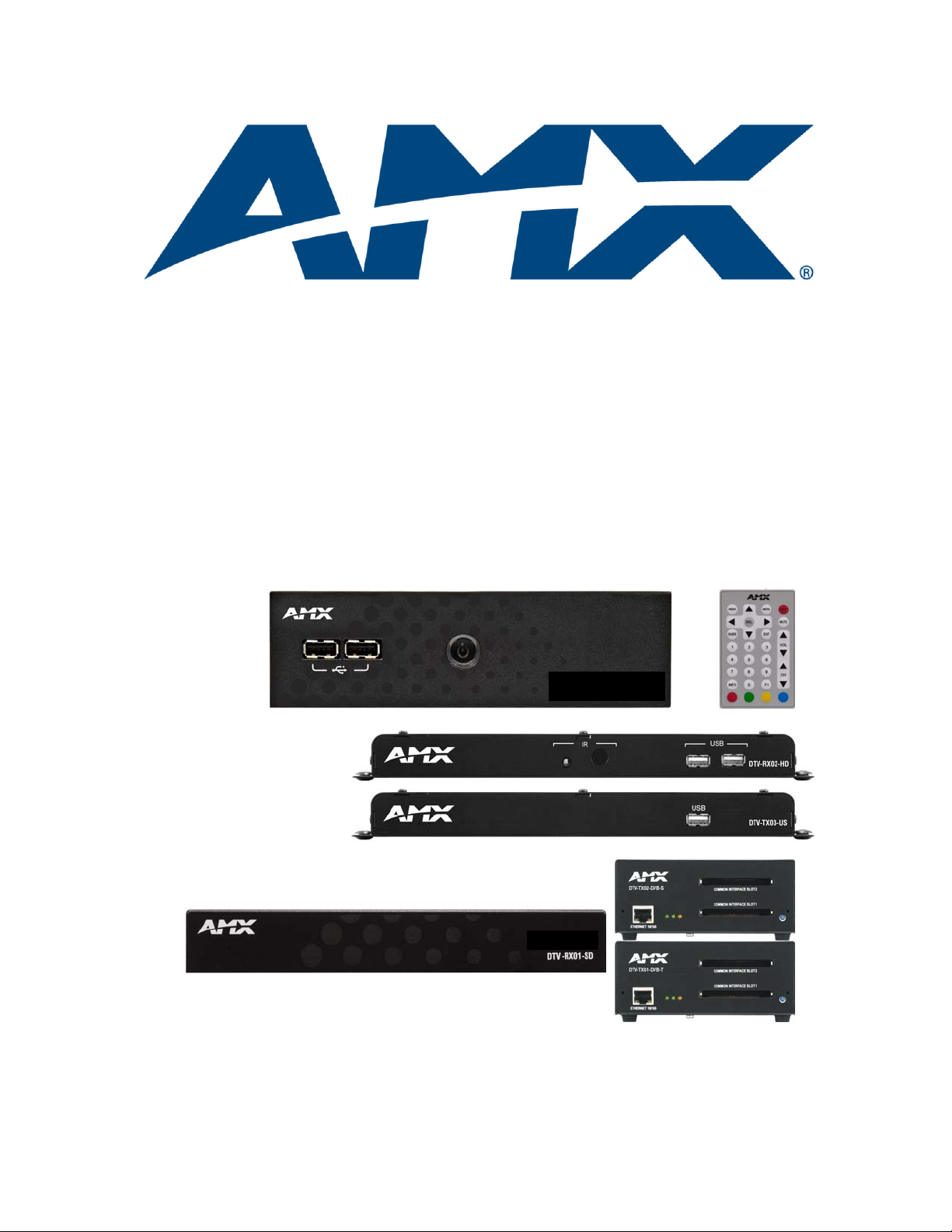
DTV-TX03-US Transmitter
DTV-RX02-HD Receiver
DTV-MA01 TDS Management Appliance
DTV-RC01 Remote Control
High-Definition (ClearQAM/ATSC)
TDS Components
Standard-Definition (DVB Terrestrial & Satellite)
TDS Components
DTV-RX01-SD Receiver
DTV-TX01-DVB-T Transmitter
DTV-TX02-DVB-S Transmitter
AMX Television Distribution System (TDS)
Overview
AMX Television Distribution Systems simplify the capture, storage and distribution of video content by
providing integrated solutions that support live video, pre-recorded video or TV signals. Using intuitive
interfaces, administrators can control incoming video or TV signals and determine where to project them,
either to a display, projector or PC. They support multicast, as well as most industry standard video file
formats plus audio. And our solutions can build on an existing video infrastructure to simplify the installation
and reduce costs in deploying a video content management system.
AMX Television Distribution System (TDS) products are designed to transmit digital TV content over
Ethernet using a multi-cast enabled LAN as opposed to a separate dedicated coaxial cable.
Television distribution is managed via the DTV-MA01 TDS Management Appliance. Use a PC to connect to
the DTV-MA01, to configure the transmitters and receivers in the system.
The AMX TDS Transmitters send a complete transport stream (MPEG2 and MPEG4, H264, as broadcast by
the service provider) which can include multiple individual channels of live programming to an AMX TDS
Receiver located at the TV display. It also sends control information over the same Ethernet network allowing
the ability to centrally manage the displays including powering them on and off. AMX TDS Receivers are
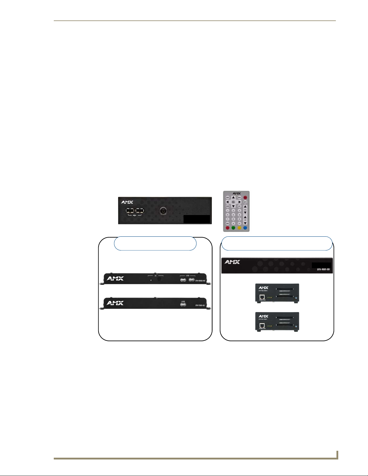
available both in High-Definition and Standard Definition models (FIG. 1).
FIG. 1 AMX TDS System Components
Network Considerations
Because of the high bandwidth associated with A/V distribution, the TDS system is typically managed via a
separate IT infrastructure. However, content may be streamed over the main network if desired. Consult your
IT representative to determine the proper network configuration for the TDS system.
The AMX TDS system transmits audio/video using IP multicast. In order for this to work satisfactorily, it is
vital that the network switches are multicast-enabled in order to prevent unwanted flooding of traffic on the
network.
Within the context of AMX TDS documentation. the term “Multicast-enabled” means that all
network switches carry out IGMP snooping, and one switch must function as the IGMP querier.
AMX TDS supports version 2 of IGMP.
Page 10
AMX Television Distribution System (TDS)
2
AMX TDS (Television Delivery System)
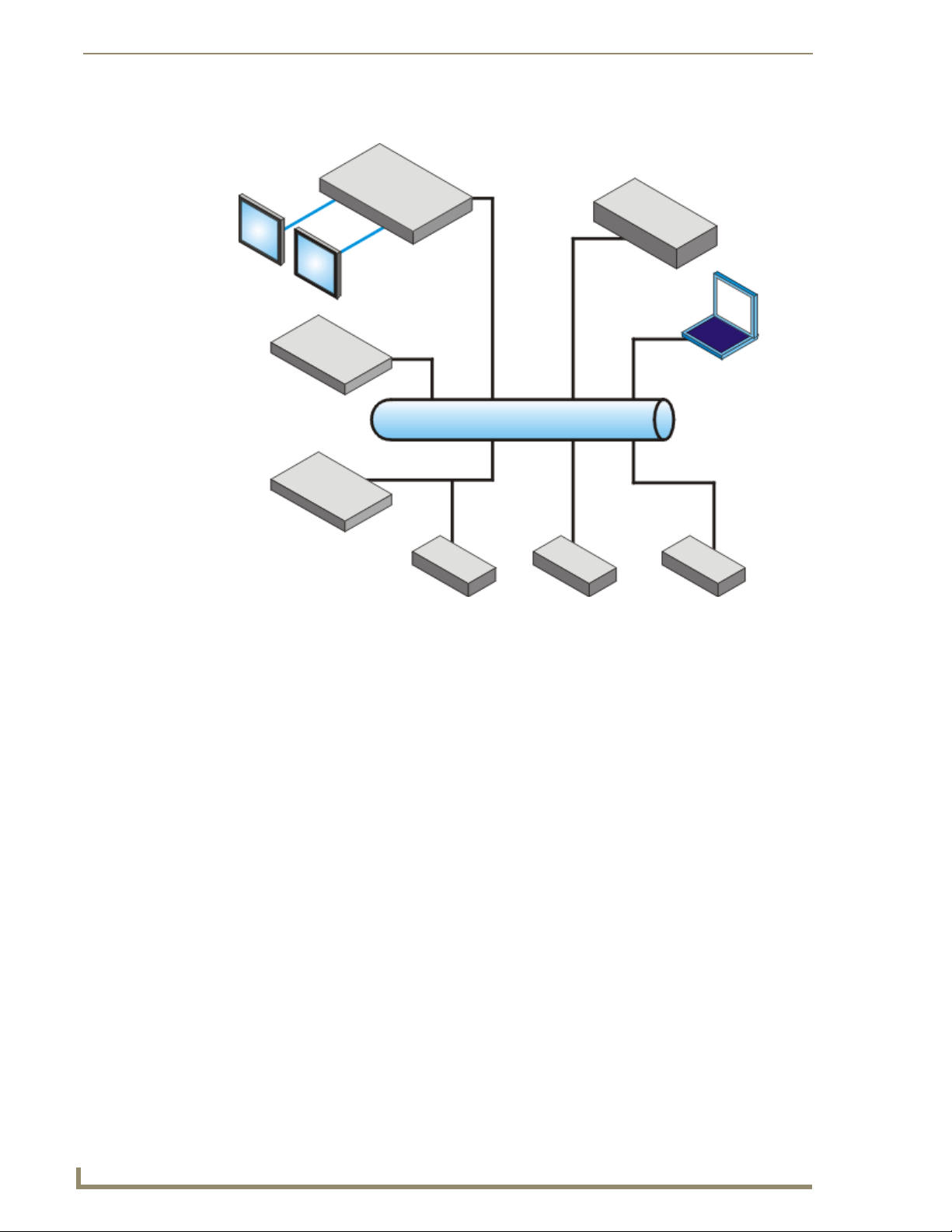
NetLinx Central Controller
DTV-MA01
DTV-RX01
DTV-RX02
DTV-TX01 DTV-TX02DTV-TX03
Touch Panel
Touch Panel
PC
LAN
System Diagram - TDS Distribution
FIG. 2 AMX TDS System Diagram
Page 11
AMX TDS - ClearQAM/ATSC (High Definition)
3
AMX TDS (Television Delivery System)
DTV-TX03-US Transmitter (front)
DTV-RX02-HD Receiver (front)
DTV-RC01 Remote Control
DTV-MA01 (front)
AMX TDS - ClearQAM/ATSC (High Definition)
Overview
This section describes the QAM/ATSC (High Definition) version of the AMX TDS, intended primarily for use
within the USA. The High Definition TDS utilizes DTV-TX03-US Digital TV Transmitters (FG1410-03) and
DTV-RX02-HD High-Definition Receivers (FG1411-02).
Note that both the High-Definition and Standard Definition versions of the AMX TDS utilize the
DTV-MA01 TDS Management Appliance (FG1412-01) and (optionally) the DTV-RC01 Digital TV Remote
Controller (FG1411-70).
FIG. 3 shows the primary components of the AMX TDS (HD) system.
FIG. 3 AMX TDS System - Component Devices (QAM-High Definition TDS)
The Terrestrial/Satellite (Standard Definition) version of the TDS is described in the
AMX TDS - Terrestrial/Satellite (Standard Definition) se ction on page 19.
System Components
The AMX TDS system consists of several components, including a Receiver (and IR Remote Controller), and
Transmitter modules.
AMX TDS - ClearQAM/ATSC (High Definition) - Component Devices
Product Name Description FG#
DTV-TX03-US Digital TV Transmitter QAM/ATSC
• For use with QAM/ATSC digital TV broadcasts
• Provides one transport stream
DTV-RX02-HD Digital TV Receiver High Definition FG1411-02
DTV-MA01 TDS Management Appliance FG1412-01
DTV-RC01 Digital TV Remote Control FG1411-70
FG1410-03
Page 12
4
AMX TDS (Television Delivery System)
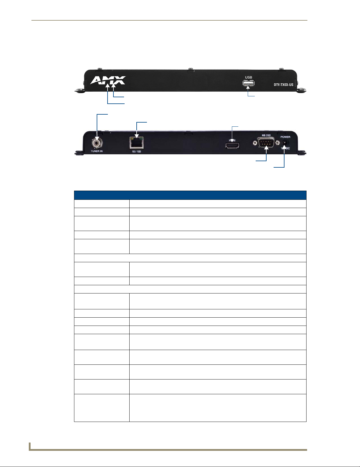
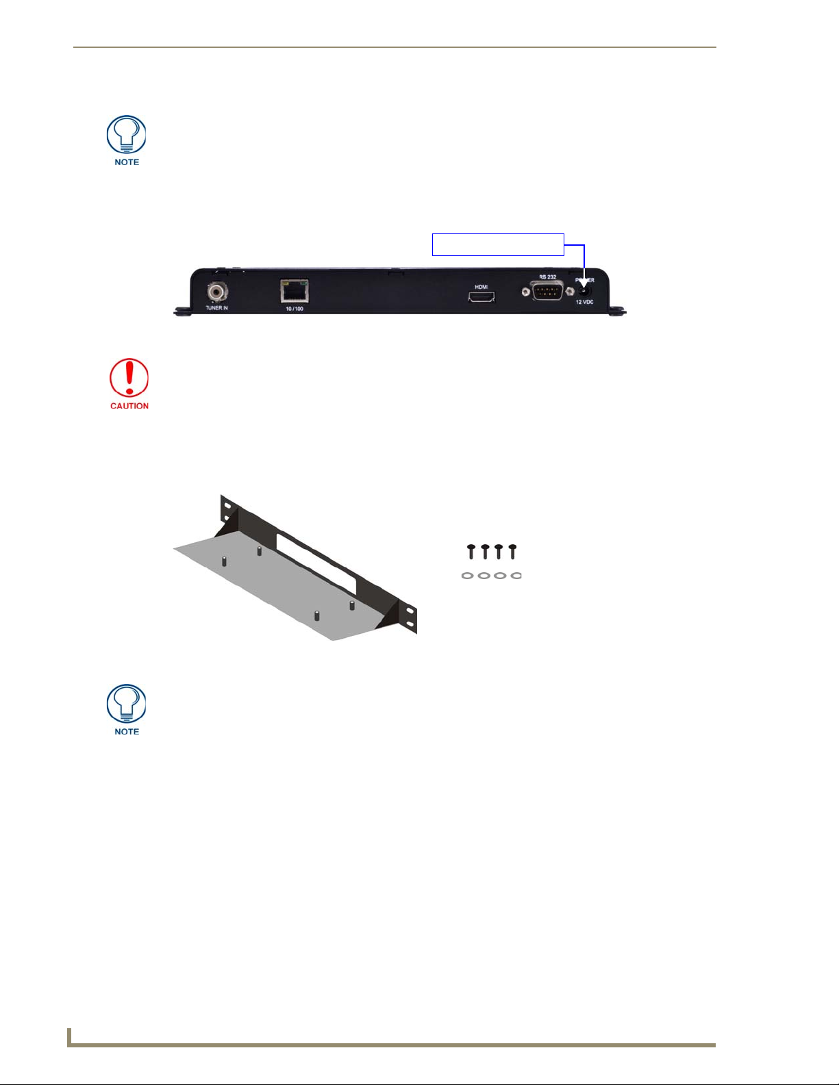
(front)
(rear)
10/100 (RJ45) Ethernet connector (to network)
RS232 Serial connector (DB9: for local device control only)
PWR connector
QAM/ATSC Tuner Input
Communication Status LED (red)
Power Status LED (green)
not used
not used
AMX TDS - ClearQAM/ATSC (High Definition)
DTV-TX03-US Transmitters
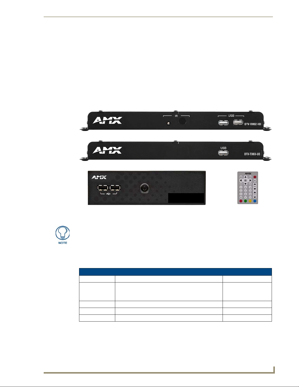
The DTV-TX03-US Digital TV Transmitter (FG1410-03) receives the incoming ClearQAM or ATSC signal
and sends the digital TV content to the DTV Receiver located at the display (FIG. 4).
FIG. 4 DTV-TX03-US Transmitter
Product Specifications
DTV-TX03-US Transmitter
Dimensions (HWD): 1" x 10.5" x 4.25" (2.54 cm x 26.67 cm x 10.76 cm)
Weight: 1 lb (0.45 kg)
Power: • Input Voltage 12VDC
Tuners: 1 internal QAM/ATSC tuner
RF Input Level: • 950 - 2150 MHz
Front Panel Components:
Status LEDs: • Power Status LED (green):
USB Connector: not used
Rear Panel Connectors:
TUNER IN (RCA) Accepts incoming QAM/ATSC signals.
10/100 (RJ45): Standard 10/100 Network (RJ45) connector (see Network Switch Requirements).
HDMI: Reserved for future implementation.
RS232 (DB9): Serial connector for local command line interface (RS232 only).
POWER: Barrel plug accepts 12VDC power from the included power supply.
Environment: • Operating Temperature: 32°F - 122°F (0°C to 50°C)
Certifications: • CE
Included Accessories: • 12V Power Supply
Other AMX Equipment: • DTV-MA01 TDS Management Appliance (FG1412-01)
• Power Dissipation 6~10 Watts
• -35 - -55 dBm
• Communication Status LED (red):
Note: Use the included Coax-to-RCA adapter on this connector.
Note: This connector is intended to be used only with the provided power supply.
• Operating Humidity: 85% (Max relative humidity, non-condensing)
• FCC part 15 Class A
• Coax-to-RCA connector adapter
• DTV-RX02-HD Receiver (FG1411-02)
• CC-232 Serial Communication Cable (FG10-752-04)
• DTV-RK-TX03 Rack-Mounting Kit (FG1410-61)
Page 13
AMX TDS - ClearQAM/ATSC (High Definition)
5
AMX TDS (Television Delivery System)
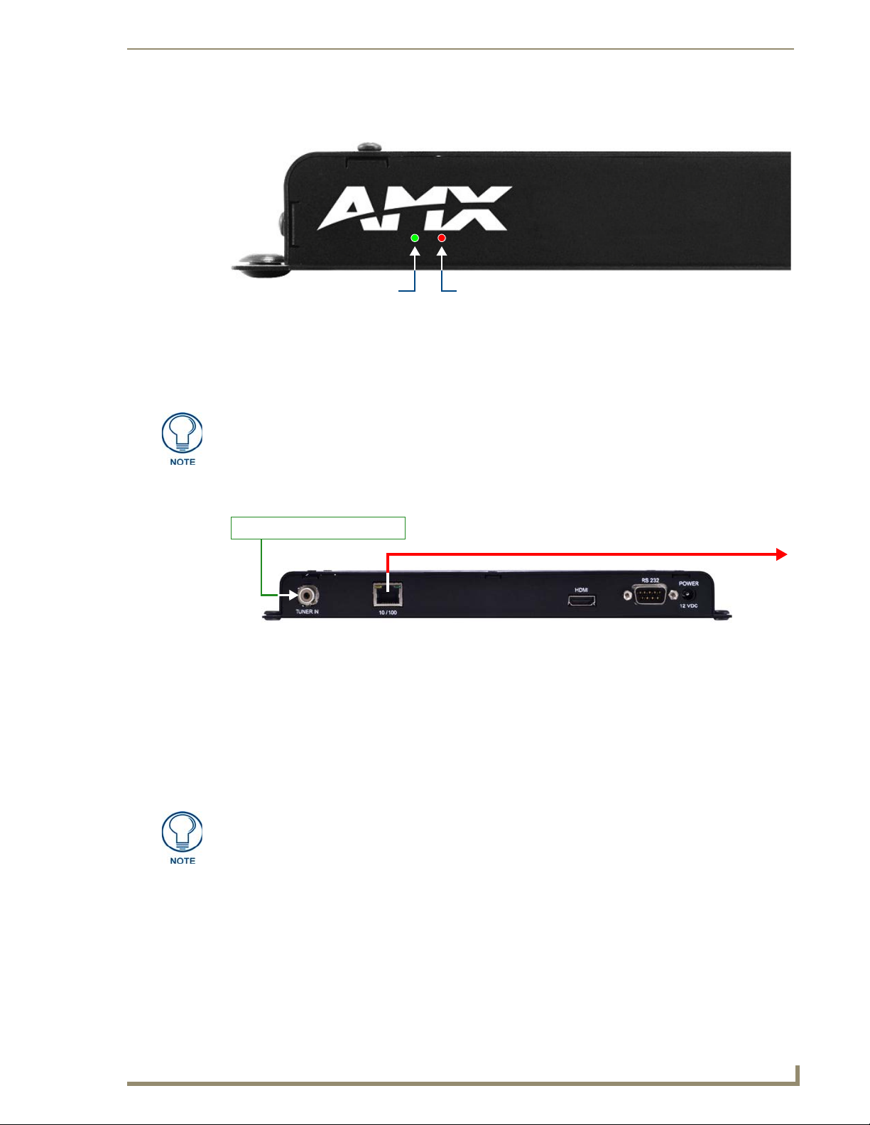
Communication Status LED (red)
Power Status LED (green)
Video is distributed via
Ethernet to DTV Receiver(s)
Incoming Digital TV Signal
Front Panel - Status LEDs
The two status LEDs are located on the front panel, directly beneath the AMX logo (FIG. 5):
FIG. 5 Status LEDs
Power Status (green): Lights to indicate that the Transmitter is receiving power and is functional. If
the LED fails to light, check your 12VDC Power connection (see the Applying Power to the
Transmitters section on page 16).
Communication Status (red): Lights to indicate that the Transmitter is connected to the network.
The USB Port on the front panel is not used at this time.
Rear Panel - TUNER IN
The TUNER IN (RCA) connector accepts incoming QAM/ATSC TV signals via coax cable (FIG. 6).
FIG. 6 TUNER IN (shown with Coax-to-RCA adapter installed)
In order to use the TUNER IN (RCA) connector with coax cable, you must first install the included
Coax-to-RCA adapter (see FIG. 25 on page 16).
Refer to the Connecting TV Sources to the Transmitter section on page 16 for details.
Recommended Signal Levels
AMX TDS Transmitters require good quality input signals. The recommended signal levels for QAM
Transmitters are:
Signal to noise ratio (SNR): > 7 - 9 dB
Bit error rate (BER): < 2E-04
For best results, only stream QAM channels with a Strength rating of 201-255, as
indicated in the Tuner Setup page (see the Transmitter Setup - Tuner Setup (DTVTX03-US) section on page 56).
Page 14
AMX TDS - ClearQAM/ATSC (High Definition)
6
AMX TDS (Television Delivery System)
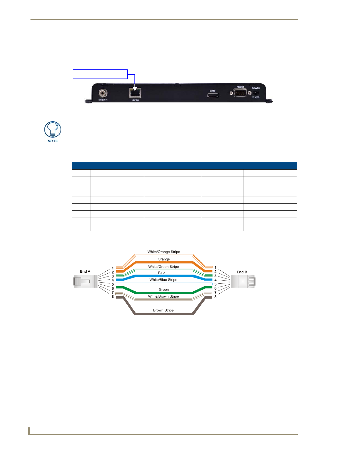
Cat5/5e/6 network cable
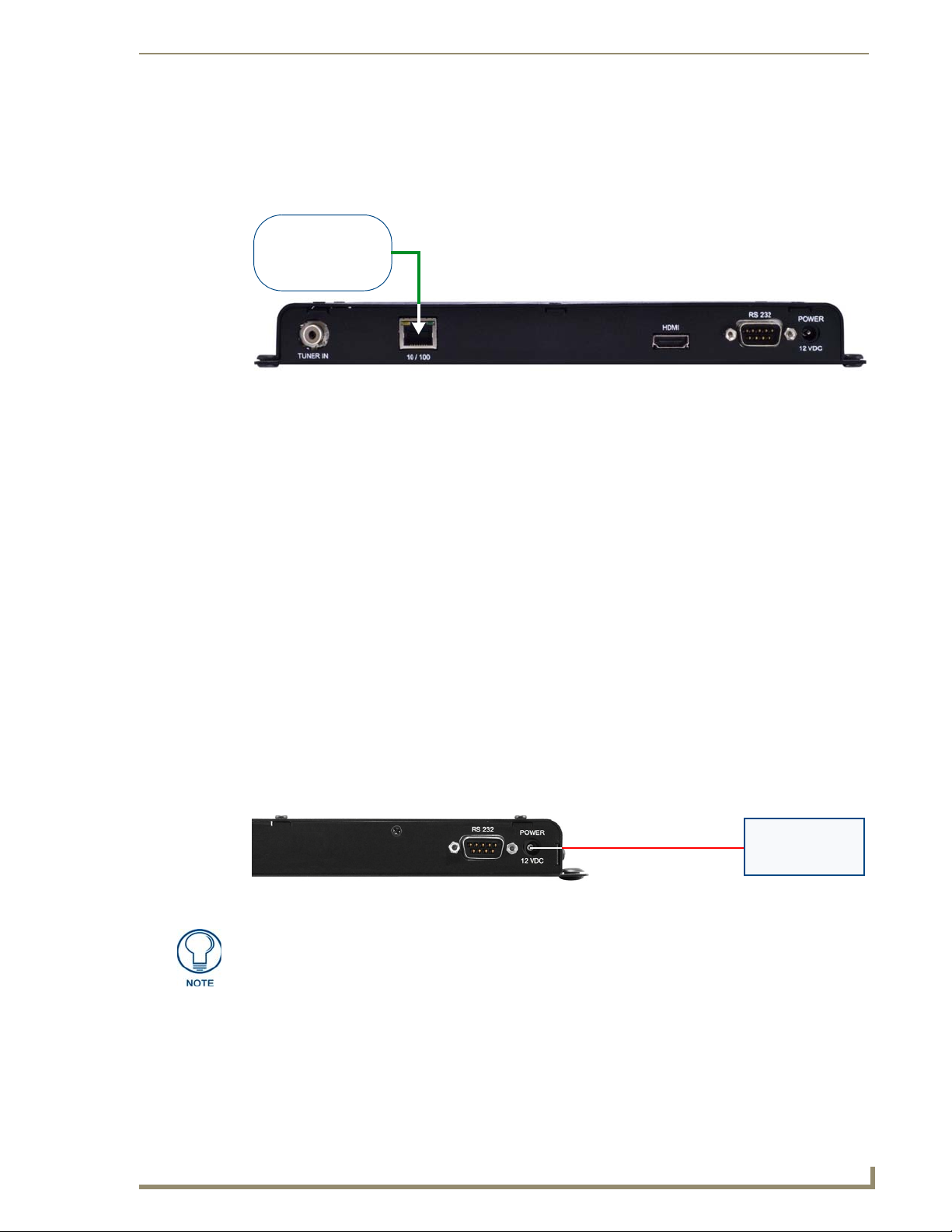
Rear Panel - 10/100 Network Port
The 10/100 (Ethernet RJ45) port on the front panel provides 10/100 BaseT network connectivity via
Cat5/5e/6 network cable (FIG. 7). Refer to the Connecting the Transmitters to the Network section on page 17
for more information.
FIG. 7 10/100 Ethernet Port
DTV-TX03-US Transmitters require Layer 3 switching. Therefore a Layer 3 Network
Switch (sometimes referred to as a "Multilayer Switch") is required to operate
properly.
10/100 Network Port Pinouts and Signals
The following table lists the pinouts, signals, and pairing for the 10/100 Network port.
10/100 Port Pinouts and Signals
Pin Signals Connections Pairing Color
1 TX + 1 --------- 1 1 --------- 2 Orange-White
2 TX - 2 --------- 2 Orange
3 RX + 3 --------- 3 3 --------- 6 Green-White
4 no connection 4 --------- 4 Blue
5 no connection 5 --------- 5 Blue-White
6 RX - 6 --------- 6 Green
7 no connection 7 --------- 7 Brown-White
8 no connection 8 --------- 8 Brown
FIG. 8 diagrams the pinouts and signals for the 10/100 Port RJ45 connector and cable. Note that while 568B
termination is shown in the figure, 568A can also be used, as long as both ends are terminated the same way.
RJ45 wiring diagram
FIG. 8
Consult the Network Administrator for correct cabling from the DTV-TX03-US Transmitter onto the network.
For remote connectivity, the Firewall may have to be configured to open port 2008 for remote
connectivity over UDP.
Ports 5000 and 5001 are required for the Transmitters as well as any ports used for the TDS
Multicast stream.
Ports 5002 and 5003 are fixed as the multicast stream output ports.
Page 15
AMX TDS - ClearQAM/ATSC (High Definition)
7
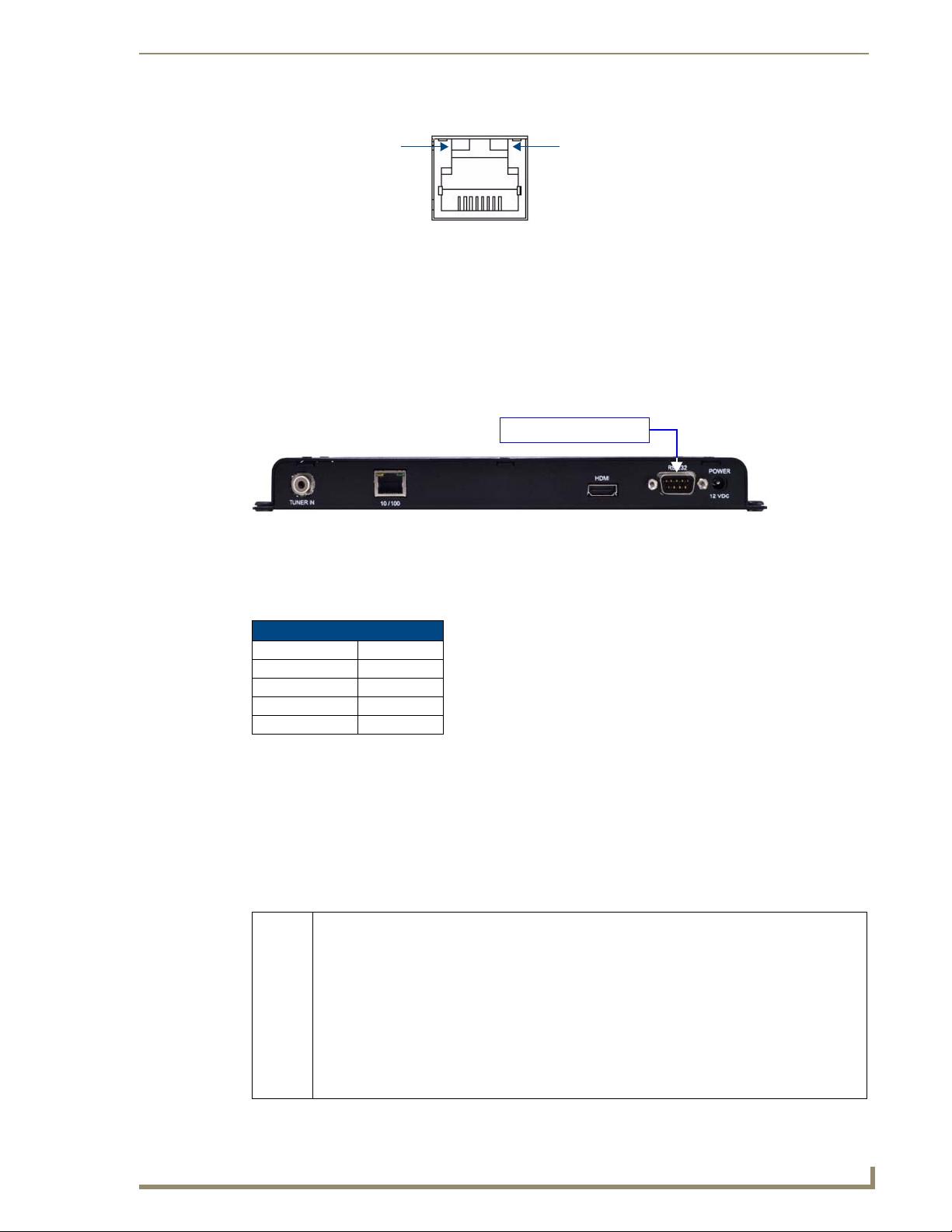
AMX TDS (Television Delivery System)
SPD - Speed LED
connection speed is 100 Mbps
and turns Off when speed is
lights (yellow) when the
L/A - Link/Activity LED
lights (green) when the
Ethernet cables are
connected and terminated
10 Mbps.
correctly.
DB9 programming cable
Ethernet LEDs
FIG. 9 Ethernet LEDs
Default IP Address
By default, DTV-TX03-US Transmitters are set to DHCP.
Network Switch Requirements
DTV-TX03-US Transmitters require a Layer 3 Gigabit Switch with multicast support,
IGMP Querier/Snooping and PIM.
Rear Panel - RS-232 Port
The RS-232 port on the rear panel provides a serial interface that provides basic diagnostics and the ability to
change the IP address, via a standard DB9 connector (FIG. 10).
FIG. 10 RS-232 Port
Use a standard DB9 programming cable such as the CC-232 (FG10-752-04, not included) to
connect to a PC for Terminal communication.
Supported terminal commands are listed in the Serial Commands section on page 79.
Use hyper terminal with default serial settings to communicate with the DTV Transmitters:
Default Serial Settings
Baud Rate: 115200
Data Bits : 8
Parity: None
Stop Bits: 1
Flow Control: None
Setting the Transmitter’s IP Address via the RS232 Port
In most cases, all setup and configuration for both Transmitters and Receivers is done via the Digital TV
Configuration Manager (see the Digital TV Configuration Manager section on page 53 for information).
However, the Transmitter’s IP Address can also be specified via serial command, using the RS232 port on the
rear panel (see FIG. 10).
In order to configure the network settings via the RS232 port, the Transmitter must be placed in command
mode. To place the Transmitter in command mode, press ’Enter’ while the unit is booting up. To reboot, recycle power by disconnecting and re-connecting the 12VDC POWER connector on the rear panel.
Use the setip lan serial command to configure the network settings:
setip lan Following prompts to configure LAN network settings. This setting takes effect immediately after the
unit boots up.
Enter DHCP option (0/1) >
Enter ipAddr:
Enter subnet:
Enter Gateway:
Enter priDNS:
Enter secDNS:
Enter DomainName:
Note: If DHCP is set, all other options to enter IP address setting will be skipped. If entry is not valid,
it will be prompted again. If second entry is still not valid, the configuration will exit without saving.
Page 16
AMX TDS - ClearQAM/ATSC (High Definition)
8
AMX TDS (Television Delivery System)
Supplied Power Adapter
4 mounting screws
4 washers
mounting shelf
All DTV Transmitters and Receivers must have an assigned IP Address, Network
Mask, and Gateway Address in order for the DTV system to work correctly. This
applies to units that utilize DHCP and to units that have been assigned Static IP
addresses. If you are using DHCP, verify tha t these ad dress assignments are
provided by the DHCP Server.
Rear Panel - POWER/12 VDC Connector
Connect the power adapter to the Transmitter, and plug the power adapter into an AC power outlet (FIG. 11).
FIG. 11 POWER/12 VDC Connector
Use ONL Y the power adapter supplied with the Transmitter . Otherwise, the unit
may be damaged.
Rack-Mounting DTV-TX03-US Transmitters
Use the DTV-RK-TX03 Rack-Mounting Kit (FG1410-61) to mount the DTV-TX03-US into a standard 19"
equipment rack. The DTV-RK-TX03 uses a single RU. The components of the Rack-Mounting Kit are shown
in FIG. 12:
FIG. 12 DTV-RK-TX03 Rack-Mounting Kit Components
Rack-mounting the DTV-TX03-US Transmitter requires four plastic grommets, which
are not included with the Rack-Mounting Kit. Rather, they are included with the
Transmitter.
The mounting base of the DTV-TX03-US Transmitter has four mounting holes that fit over the posts on the
mounting shelf.
1. Align the mounting holes on the Transmitter with the mounting posts on the Mounting Shelf (FIG. 13).
Page 17
AMX TDS - ClearQAM/ATSC (High Definition)
9
AMX TDS (Television Delivery System)
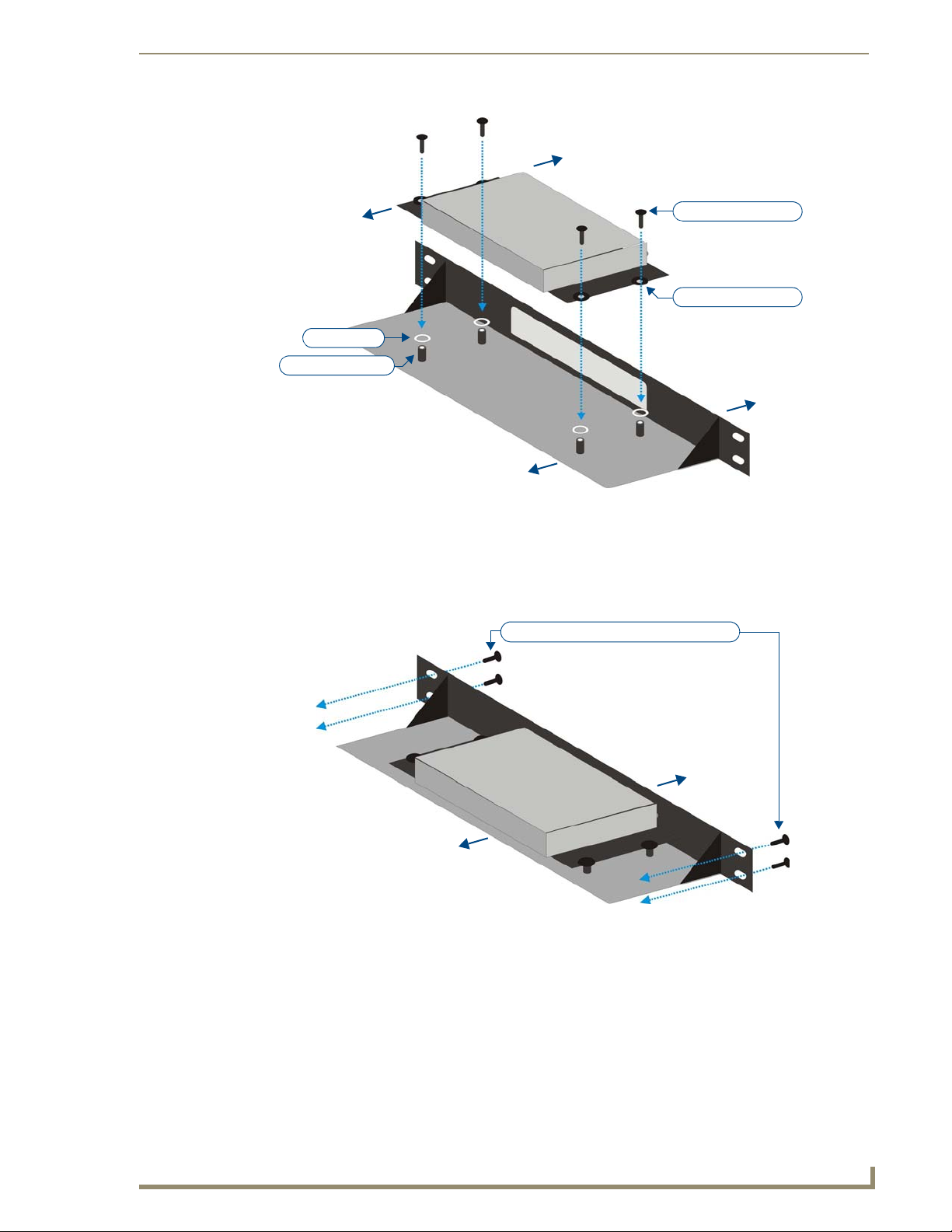
front
rear
DTV-TX03-US Transmitter
Mounting Shelf
front
rear
Washer (x4)
Mounting Post (x4)
Mounting Hole (x4)
Mounting Screw (x4)
front
rear
Rack-mounting screws (x4, not included)
FIG. 13 Placing the Transmitter on the mounting posts
2. Insert a washer between each Mounting Post on the shelf and matching Mounting Hole on the
Transmitter.
3. Use the supplied mounting screws to secure the Transmitter to the Mounting Shelf.
4. Once the Transmitter is secured to the Mounting Shelf, the entire assembly can be mounted into the
equipment rack using four rack screws (not included - FIG. 14).
FIG. 14 Placing the Transmitter on the mounting posts
Page 18

AMX TDS - ClearQAM/ATSC (High Definition)
10
AMX TDS (Television Delivery System)
CVBS digital video Out
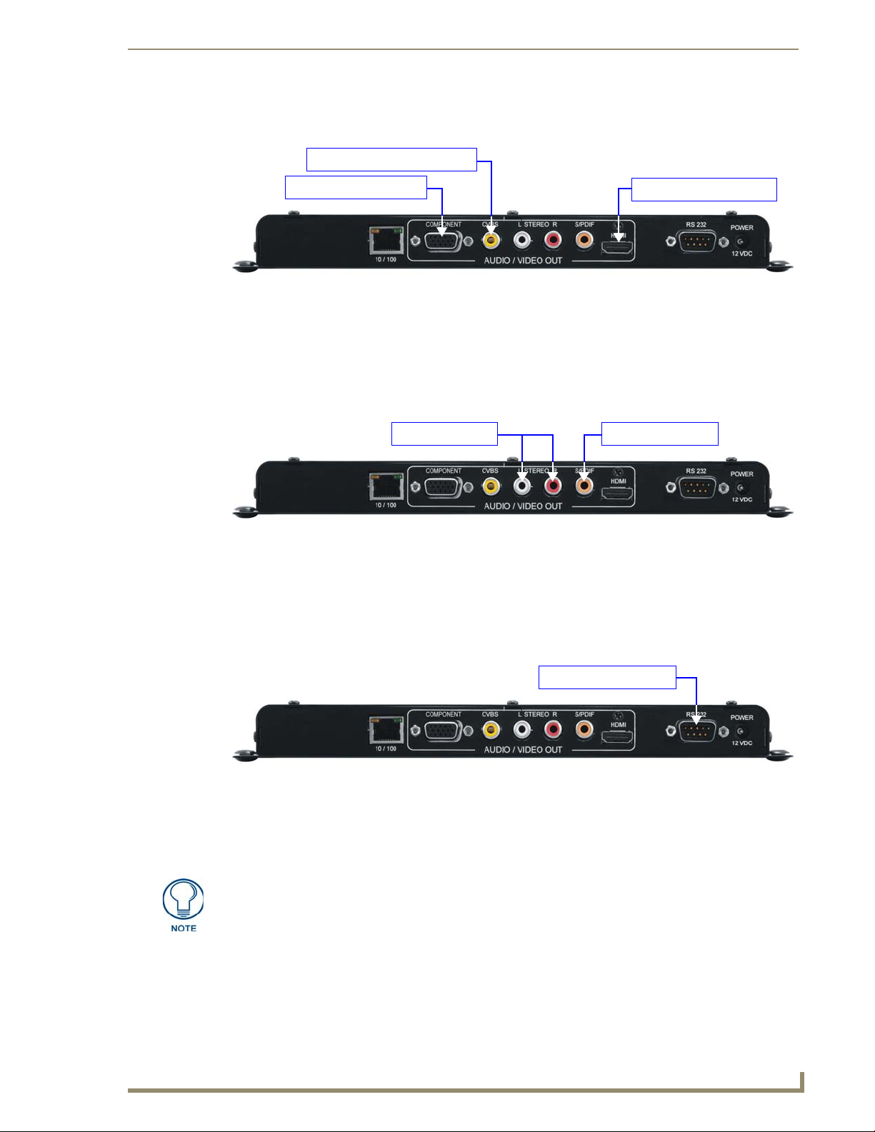
SPDIF digital audio OutAnalog audio Out (L/R)
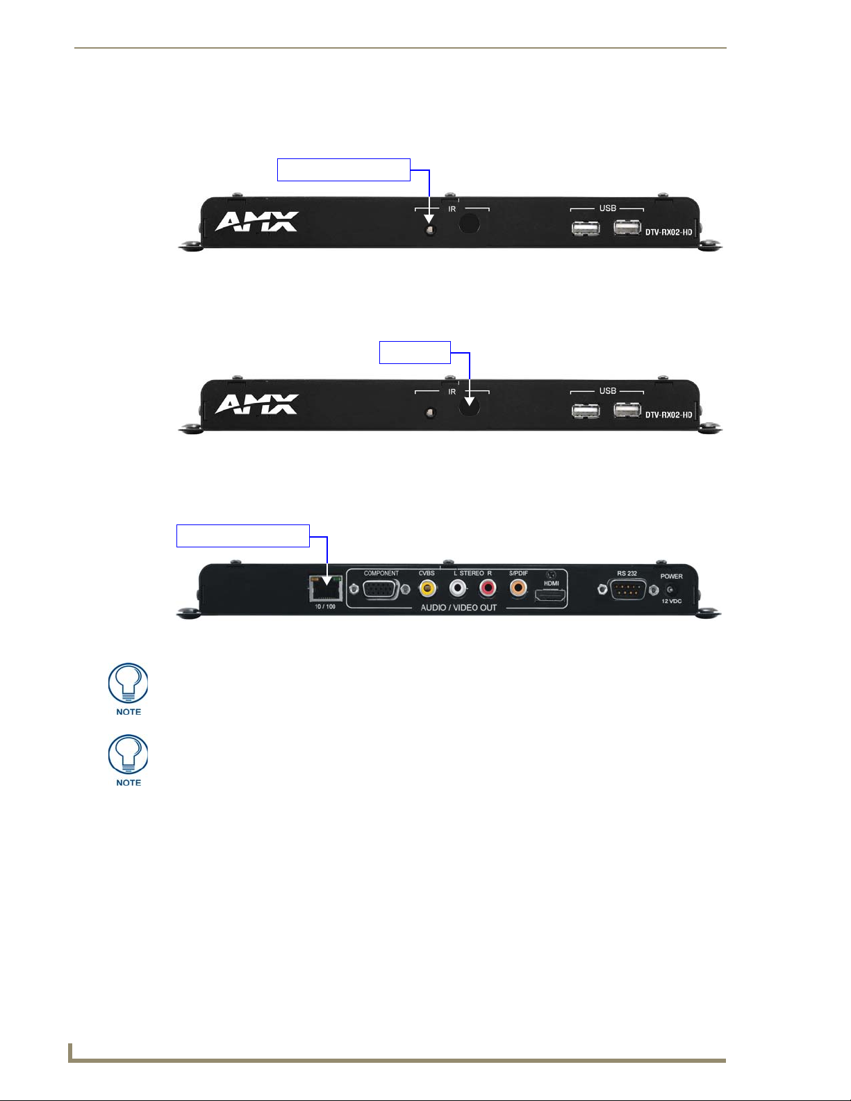
(front)
IR Receiver
RS232 Serial connector
(DB9: for local device control only)
PWR connector
10/100 (RJ45) Ethernet
connector (to network)
Component video Out HDMI video Out
not used
(rear)
External IR Receiver socket
DTV-RX02-HD Receivers
The DTV-RX02-HD High-Definition Receiver (FG1411-02) is located at the display and receives incoming
transmitted digital TV signal (from a DTV Transmitter), and converts it to a compatible format for a target
display in High Definition (FIG. 15).
FIG. 15 DTV-RX02-HD Receiver
Trademark Acknowledgement
The design of the DTV-RX02-HD was approved by Dolby™.
Manufactured under license from Dolby Laboratories. Dolby and the double-D symbol are trademarks of
Dolby Laboratories.
Product Specifications
Product Specifications - DTV-RX02-HD Receiver
Dimensions (HWD): 1" x 10.5" x 4.25" (2.54 cm x 26.67 cm x 10.76 cm)
Weight: 0.90 lbs (0. 41 kg)
Power: • Input Voltage 12VDC
• Power Dissipation 6~10 Watts
Front Panel Components
External IR Receiver
Socket:
IR Receiver: The IR Receiver on the front panel allows the DTV-RX02-HD to use the DTV-RC01
USB Ports: not used
Rear Panel Connectors
10/100 (RJ45): Standard 10/100 Network (RJ45) connector.
AUDIO / VIDEO OUT
Connectors:
RS232 (DB9): Serial connector for local command line interface (RS232 only).
Connects to External IR Receiver (60-1411-01)
Digital TV Remote Control for channel selection and control of local monitor
volume and power.
Note: The DTV-RX02-HD does not support PoE power.
• COMPONENT: 15-pin connector provides Component video output.
• CVBS: RCA connector provides Composite video output.
• L / R Stereo: RCA connectors provide L /R Analog audio output.
• SPDIF: RCA connector provides Digital audio output.
• HDMI: HDMI connector provides HDMI video output.
Note: See for a listing of supported video output resolutions.
Mainly used for control of TV , and can be used for changing IP (see the Setting the
Receiver’s IP Address via the RS 232 Port section on page 14 for details).
Page 19
AMX TDS - ClearQAM/ATSC (High Definition)
11
AMX TDS (Television Delivery System)
Product Specifications - DTV-RX02-HD Receiver (Cont.)
Rear Panel Connectors (Cont.)
POWER: Barrel plug accepts 12VDC power from the included power supply.
Note: This connector is intended to be used only with the provided power supply.
Operating Environment: • Temperature: 35°F - 95°F (5°C - 35°C)
• Humidity: Max. relative humidity - 85% (non-condensing)
Certifications: • CE
• FCC part 15 Class A
Included Accessories: • 12 VDC Power Supply
• DTV-RC01 Digital TV Remote Control (FG1411-70)
• External IR Receiver (60-1411-01)
Other AMX Equipment: • DTV-MA01 TDS Management Appliance (FG1412-01)
• DTV-TX01-DVB-T Transmitter (FG1410-01)
• DTV-TX02-DVB-S Transmitter (FG1410-02)
• DTV-TX03-US Transmitter (FG1410-03)
• CC-232 Serial Communication Cable (FG10-752-04)
Feature Comparison - HD vs SD Receivers
The following table provides a summarized feature comparison for the DTV-RX01-SD (Standard Definition)
Receivers and DTV-RX02-HD (High-Definition) Receivers:
Feature Comparison - HD vs SD Receivers
Feature DTV-RX01-SD (FG1411-01) DTV-RX02-HD (FG1411-02)
Definition Standard (PAL or NTSC) High (to 1080p)
Video Decoding MPEG2 MPEG2, MPEG4pt2 and MPEG4pt10 (H.264)
Audio Decoding MPEG2 MPEG2, MPEG2layer3 (MP3), AC-3
Subtitles ETSI EN 300 743 EIA-608 (encoded line 21)
IP Stream decoding UDP UDP
PoE Yes No
IR Remote (SC-31) Yes Yes
IR Remote (SC-33) Yes No
Display Control - IR Yes No
Display Control - Serial Yes Yes
Control Menu Yes Yes
On Screen Display OSD Yes No
MAX CSE support No Yes
Refer to the DTV-RX01-SD Receivers section on page 29 for detailed information on the Standard Definition
DTV Receivers.
DTV-RX02-HD Receivers - Supported Output Resolutions
The following table lists all video output resolutions supported by the DTV-RX02-HD Receivers:
DTV-RX02-HD Receivers - Supported Output Resolutions
• 1920 x 1080p / 60Hz (*) • 1080p / 50Hz (*)
• 1920 x 1080i / 60Hz (*) • 1080i / 50Hz (*)
• 1280 x 720p / 60Hz (*) • 720p / 50Hz (*)
• 480p / 60Hz • 576p / 50Hz (*)
• 480i / 60Hz • 576i / 50Hz (*)
Note: The asterisk (*) indicates dual output with HDMI/Component
Subtitle Support
DTV-RX02-HD Receivers do not support the display of subtitles.
Page 20
AMX TDS - ClearQAM/ATSC (High Definition)
12
AMX TDS (Television Delivery System)
External IR Receiver
IR Receiver
Cat5/5e/6 network cable
Front Panel - External IR Receiver Socket
The IR Receiver socket on the front panel (FIG. 16) connects to the included External IR Receiver
(60-1411-01).
FIG. 16 External IR Receiver Socket
Front Panel - IR Receiver
The IR Receiver on the front panel allows the DTV-RX02-HD to use the DTV-RC01 Digital TV Remote
Control (included) for channel selection and control of local monitor volume and power (FIG. 17).
FIG. 17 IR Receiver
Rear Panel - 10/100 Network Port
The NETWORK (RJ45) port provides 10/100 BaseT network connectivity (FIG. 18). Refer to the Connecting
DTV-RX02-HD Receivers to the Network section on page 18 for more information.
FIG. 18 10/100 Network Port
The maximum distance that a Receiver can be mounted from the Network
Switch is 100m (328’).
Consult the Network Administrator for correct cabling from the DTV-RX02 Receiver
onto the network. For remote connectivity, the Receivers will use ports 2008, 5000,
5001, 5002 and 5003 for remote connectivity over UDP.
Default IP Address
By default, DTV Receivers are set to DHCP.
Network Port Pinouts and Signals
Refer to the 10/100 Network Port Pinouts and Signals section on page 6.
Ethernet LEDs
Refer to the Ethernet LEDs section on page 7.
Page 21
AMX TDS - ClearQAM/ATSC (High Definition)
13
AMX TDS (Television Delivery System)
Component Video cable
CVBS Composite Video cable
HDMI Audio/Video cable
RCA Stereo cable Digital cable
DB9 programming cable
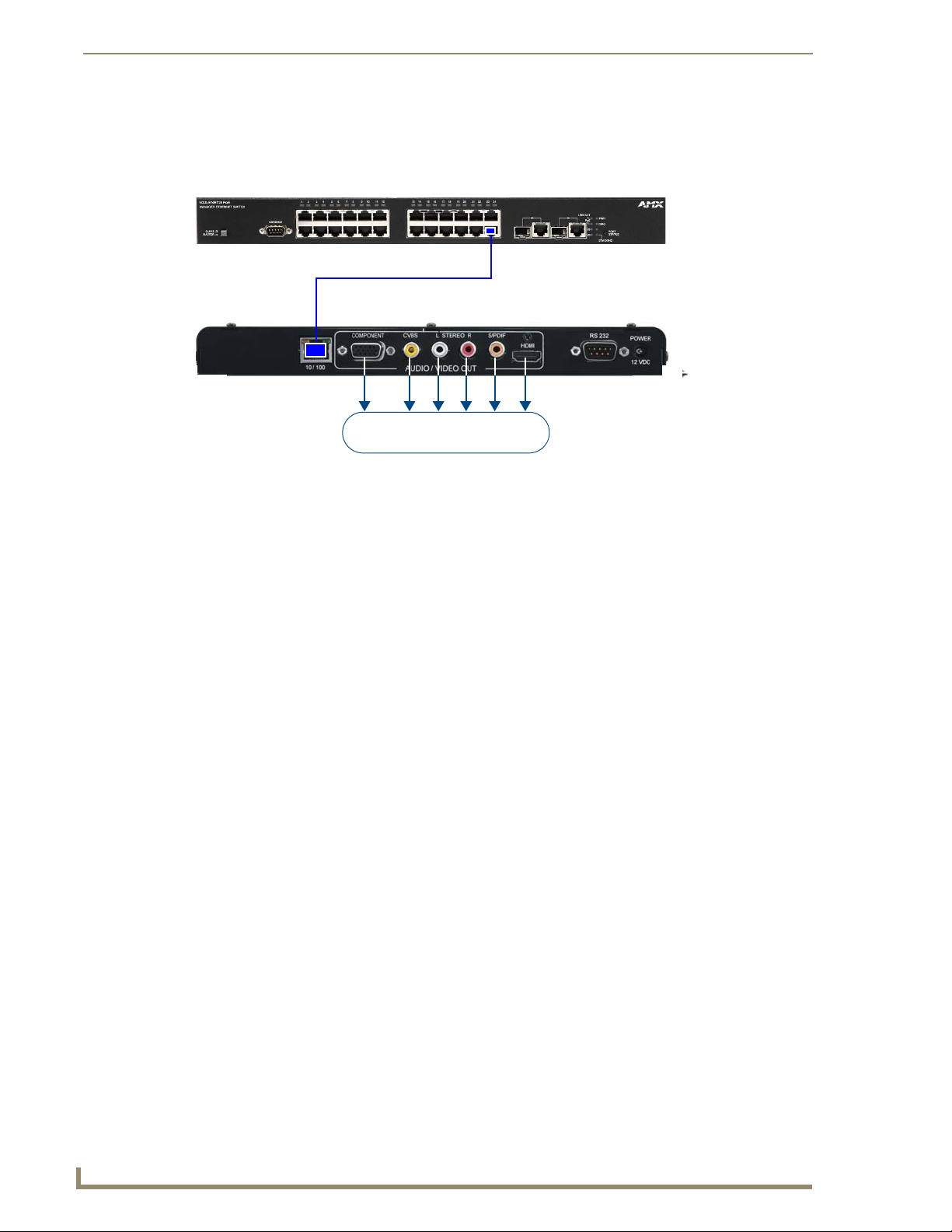
Rear Panel - Video Output Connectors
The Video Output connectors contained within the AUDIO/VIDEO OUT group on the rear panel (FIG. 19):
FIG. 19 Video Output Connectors
COMPONENT: The black 15-pin connector provides Component video output.
CVBS: The yellow CVBS RCA connector provides Composite video output.
HDMI: The HDMI connector provides HDMI audio/video output.
Rear Panel - Audio Output Connectors
The Audio Output connectors are contained within the AUDIO/VIDEO OUT group on the rear panel
(FIG. 20):
FIG. 20 Audio Output Connectors
Analog: Standard red and white AUDIO RCA connectors provide analog stereo audio output
(White = Left, Red = Right).
Digital: The orange SPDIF RCA connector provides digital audio output.
Rear Panel - RS 232 Port
The RS-232 Port on the rear panel provides a RS232 serial interface for local device control, as well as
diagnostic and troubleshooting purposes, via a standard DB9 connector (FIG. 21).
FIG. 21 RS 232 Port
Use a standard DB9 programming cable such as the CC-232 (FG10-727, not included) to connect
to a PC for Terminal control.
Supported terminal commands are listed in the ClearQAM/ATSC (High Definition) Serial
Commands section on page 79.
Connecting the Serial port on the DTV Transmitters is not an essential step in the
installation process. While the Serial port can be used for many of the same
configuration options and control/diagnostics/troubleshooting functions, in most
cases it is preferable to use the Digital TV Configuration Manager to perform these
tasks. See the Digital TV Configuration Manager section on page 53 for details
Page 22
AMX TDS - ClearQAM/ATSC (High Definition)
14
AMX TDS (Television Delivery System)
Supplied Power Adapter
Use hyper terminal with default serial settings to communicate with the DTV Transmitters:
Default Serial Settings
Baud Rate: 115200
Data Bits: 8
Parity: None
Stop Bits: 1
Flow Control: None
Setting the Receiver’s IP Address via the RS 232 Port
In most cases, all setup and configuration for both Transmitters and Receivers is done via the Digital TV
Configuration Manager (see the Digital TV Configuration Manager section on page 53 for information).
However, the Receiver’s IP Address can also be specified using a local command line interface, accessible via
the RS 232 (DB9) port on the rear panel (see FIG. 10 on page 7).
In order to configure the network settings via the RS 232 Port, the Receiver must be placed in Command
mode. To place the Receiver in Command mode, press Enter while the unit is booting up.
To reboot, re-cycle power to the unit by disconnecting and re-connecting the 12VDC POWER connector on
the rear panel.
Use the following command to configure the network settings:
setip lan Following prompts to configure LAN network settings. This setting takes effect immediately after the
unit boots up.
Enter DHCP option (0/1) >
Enter ipAddr:
Enter subnet:
Enter Gateway:
Enter priDNS:
Enter secDNS:
Enter DomainName:
Note: If DHCP is set, all other options to enter IP address setting will be skipped. If entry is not valid,
it will be prompted again. If second entry is still not valid, the configuration will exit without saving.
All DTV Transmitters and Receivers must have an assigned IP Address, Network
Mask, and Gateway Address in order for the DTV system to work correctly. This
applies to units that utilize DHCP and to units that have been assigned Static IP
addresses. If you are using DHCP, verify tha t these ad dress assignments are
provided by the DHCP Server.
Refer to the Serial Commands section on page 79 for a listing of all supported Serial commands.
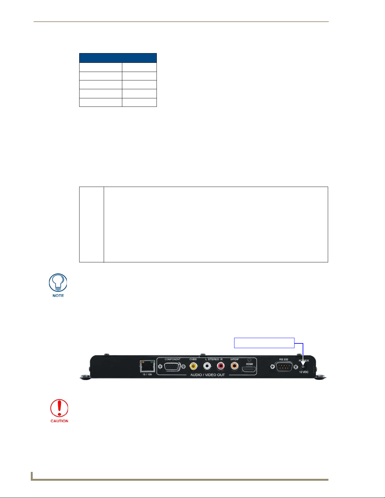
Rear Panel - POWER/12 VDC Connector
Connect the power adapter to the Transmitter, and plug the power adapter into an AC power outlet (FIG. 22).
FIG. 22 POWER/12 VDC Connector
Use ONLY the power adapter supplied with the Receiver. Otherwise, the unit
may be damaged.
Page 23
AMX TDS - ClearQAM/ATSC (High Definition)
15
AMX TDS (Television Delivery System)
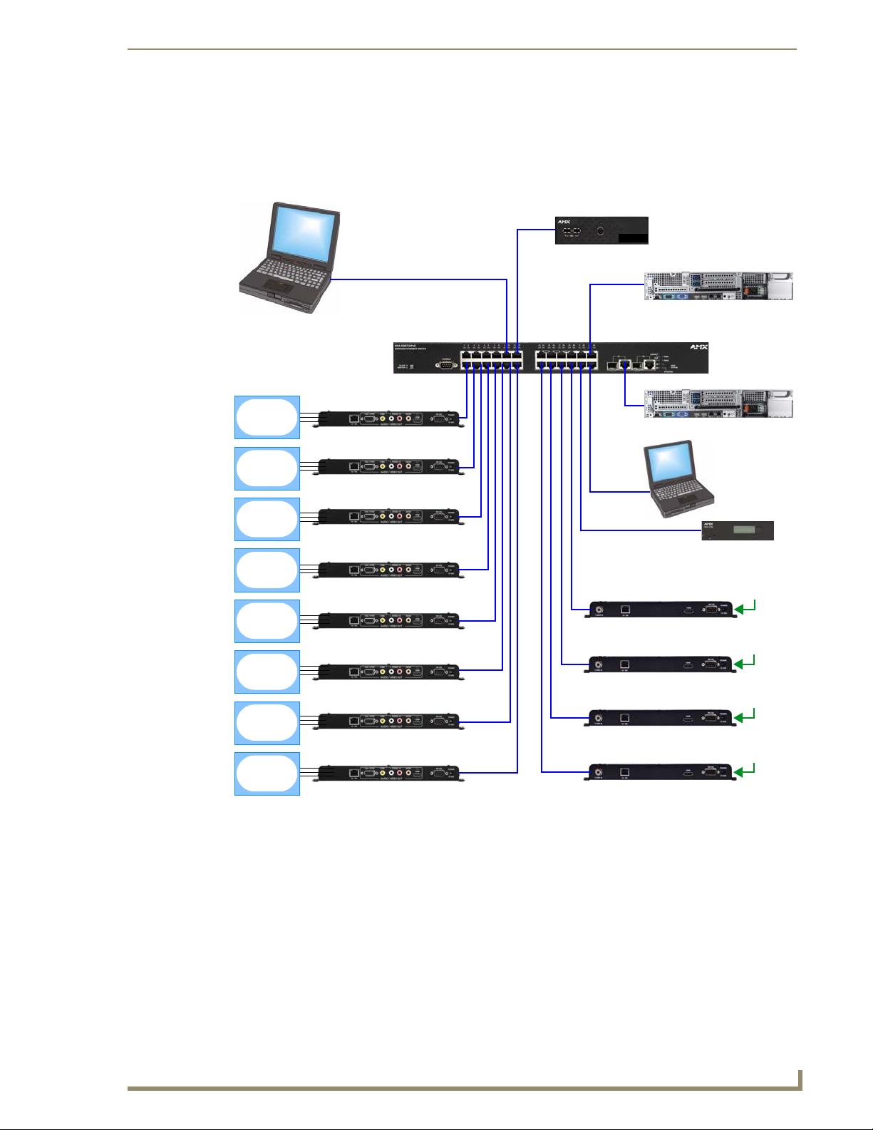
Incoming TV signal
DTV-TX03-US Transmitter
Incoming TV signal
DTV-TX03-US Transmitter
Incoming TV signal
DTV-TX03-US Transmitter
DTV-RX02-HD Receiver
DTV-RX02-HD Receiver
DTV-RX02-HD Receiver
DTV-RX02-HD Receiver
DTV-RX02-HD Receiver
DTV-RX02-HD Receiver
DTV-RX02-HD Receiver
DTV-RX02-HD Receiver
Incoming TV signal
DTV-TX03-US Transmitter
(front)
PoE Network Switcher
PC
MAX-CSE
PC providing
multi-cast video
stream
providing DVD
video output
Display Device
Display Device
Display Device
Display Device
Display Device
Display Device
Display Device
Display Device
Provides access to
the TDS Configuration
Manager
Video Server
providing multi-cast
video stream
DHCP Server
(Layer 3 Switching required)
DTV-MA01
TDS Management Appliance
Wiring and Connections
FIG. 23 illustrates a common system installation of the AMX TDS ClearQAM/ATSC (High Definition)
System:
FIG. 23 AMX TDS - Network Configuration
Page 24
AMX TDS - ClearQAM/ATSC (High Definition)
16
AMX TDS (Television Delivery System)
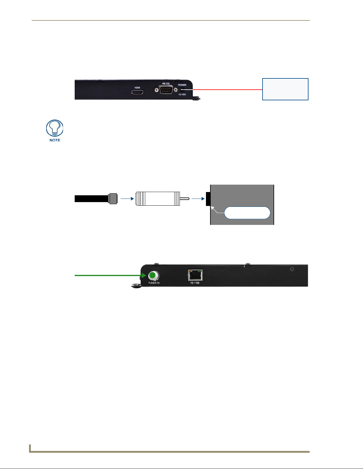
(rear)
Power Supply
TUNER IN
(RCA) connector
Coax-to-RCA adapterCoax cable
(Type-F connector)
DTV-TX03-US
Coax
TUNER IN:
Incoming ATSC/QAM
digital TV signal
Installing DTV-TX03-US Transmitters
Applying Power to the Transmitters
Each DTV-TX03-US Transmitter receives 12 VDC power via the 12VDC POWER connector on the rear panel
(FIG. 24).
FIG. 24 Applying Power to the Transmitters
This connector is intended to be used only with the provided power supply.
Connecting TV Sources to the Transmitter
DTV-TX03-US Transmitters receive QAM/ATSC digital TV broadcasts, and connect to a cable outlet via the
TUNER IN (RCA) connector.
In order to use the TUNER IN connector with coax cable, you must first install the included Coax-to-RCA
adapter (FIG. 25):
FIG. 25 Installing the Coax-to-RCA Connector Adapter on the TUNER IN (RCA) port
Connecting a Digital Cable TV Source to DTV-TX03-US Transmitters
To connect from cable to the DTV-TX03-US, use coax cable with an F-type connector (FIG. 26):
FIG. 26 Connecting a ATSC/AQM Digital TV signal to DTV-TX03-US Transmitters
Recommended Signal Levels
AMX DTV Transmitters require good quality input signals. The recommended signal levels are specified
below.
ATSC:
Signal level: > 45 dBµV and < 70 dBµV
Signal to noise ratio (SNR): > 26dB
Bit Error Rate (BER): < 2E-04
QAM:
Signal to noise ratio (SNR): > 7 - 9 dB
Bit error rate (BER): < 2E-04
Page 25
AMX TDS - ClearQAM/ATSC (High Definition)
17
AMX TDS (Television Delivery System)
Connect to LAN
(via Network Switcher)
(rear)
Power Supply
Connecting the Transmitters to the Network
DTV-TX03-US Transmitters require Layer 3 switching. Therefore a Layer 3 Network Switch (sometimes
referred to as a "Multilayer Switch") is required to operate properly.
Use the ETHERNET 10/100 Port on the front panel of the DTV-TX03-US Transmitter to connect each
Transmitter to the network, via Cat5/5e/6 UTP network cable (FIG. 27).
FIG. 27 Connecting the Transmitters to the Network
Refer to the Rear Panel - 10/100 Network Port section on page 6 for details on the 10/100 Network
Port, including Pinouts and Signals information, and descriptions of the port LEDs.
Network Configuration for the Transmitters is done via the Digital TV Configuration Manager (see
the Transmitter Setup - Network Settings section on page 54 for information).
By default, DTV-TX03-US Transmitters are set to DHCP.
Configuring DTV-TX03-US Transmitters
The Transmitters are configured via the Digital TV Configuration Manager. See the Transmitter Setup
Pages section on page 54 for information.
Installing DTV-RX02-HD Receivers
DTV-RX02-HD Receivers receive TDS broadcasts from DTV-TX03-US Transmitters (via Ethernet), and pass
the signal to the end display-device via standard A/V connectors.
DTV-RX02-HD Receivers do not connect directly to the Transmitters. Rather, they connect to Transmitters
indirectly via the LAN (using a network switch).
One DTV-RX02-HD Receiver is required for each display device. The Receivers are designed to be
mounted on or near the display devices.
Each DTV-RC01 remote controller is associated with a Receiver via options in the Digital TV
Configuration Manager. See the Receiver Setup Pagessection on page 66 for instructions.
Applying Power to the Receivers
Each DTV-RX02-HD Receiver receives 12 VDC power via the 12VDC POWER connector on the rear panel
(FIG. 28).
FIG. 28 Applying Power to the Receiver
This connector is intended to be used only with the provided power supply.
Page 26
AMX TDS - ClearQAM/ATSC (High Definition)
18
AMX TDS (Television Delivery System)
Standard A/V connectors connect
the Receiver to the display device
Network Switcher
DTV-RX02-HD Receiver
Cat5/5e/6
Connecting DTV-RX02-HD Receivers to the Network
Use standard (Cat5/5e/6 UTP) network cable to connect the DTV-RX02-HD Receivers to a network switcher.
DTV-RX02-HD Receivers feature standard A/V connectors to deliver the incoming TV signal to the display
device (FIG. 29).
FIG. 29 Connecting DTV-TX01 Transmitters to DTV-RX02-HD Receivers
Refer to the DTV-RX02-HD Receivers section on page 10 for detailed descriptions of the connectors and A/V
outputs available on the Receivers.
Connecting an (Optional) Remote IR Receiver to DTV-RX02-HD Receivers
Use the External IR Receiver socket on the front panel to connect the included External IR Receiver
(60-1411-01). The IR Receiver provides wired IR control of the RX02.
Configuring DTV-RX02-HD Receivers
The Receivers are configured via the Digital TV Configuration Manager. See the Receiver Setup Pages section
on page 66 for information.
Page 27
AMX TDS - Terrestrial/Satellite (Standard Definition)
19
AMX TDS (Television Delivery System)
DTV-RC01 Remote Control
DTV-MA01 TDS Management Appliance (front)
DTV-RX01-SD Receiver (front)
DTV-TX01-DVB-T Transmitter (front) DTV-TX02-DVB-S Transmitter (front)
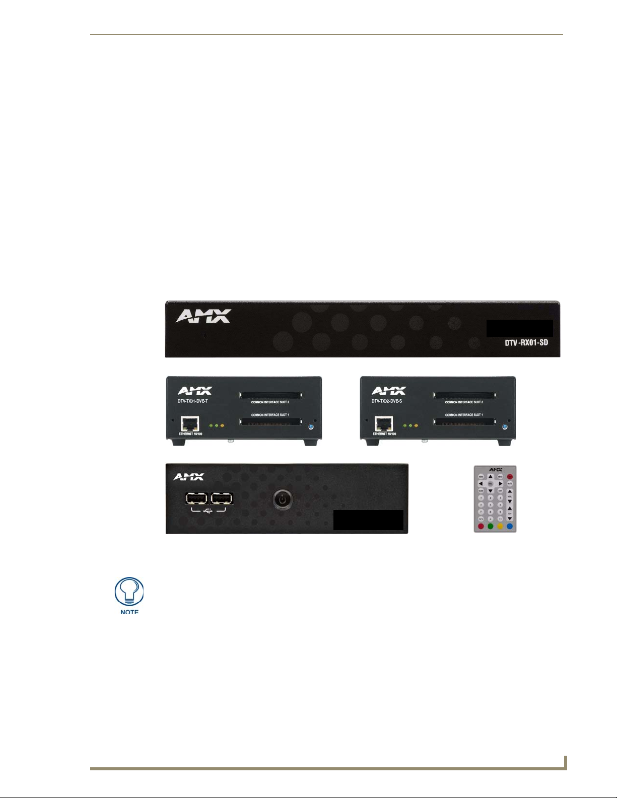
AMX TDS - Terrestrial/Satellite (Standard
Definition)
Overview
This section describes the Terrestrial/Satellite (Standard Definition) version of the AMX TDS, intended
primarily for use outside the USA. The Standard Definition TDS utilizes DTV-TX01-DVB-T (FG1410-01)
and DTV-TX02-DVB-S (FG1410-02) Digital TV Transmitters, and DTV-RX01-SD Receivers (FG1411-01).
There are two versions of the Standard Definition DTV-TX Digital TV Transmitter:
DTV-TX01-DVB-T - The DTV-TX01-DVB-T Transmitter supports DVB-T (terrestrial) signals.
The DTV-TX01-DVB-T features RF 1/2 OUT output connectors to allow multiple streams for
maximum channel coverage.
DTV-TX02-DVB-S - The DTV-TX02-DVB-S Transmitter supports DVB-S (satellite) signals.
Note that both the High-Definition and Standard Definition versions of the AMX TDS utilize the DTV-MA01
TDS Management Appliance (FG1412-01) and (optionally) the DTV-RC01 Digital TV Remote Controller
(FG1411-70).
FIG. 30 AMX TDS System - Component Devices (Standard Definition TDS)
The ClearQAM/ATSC (High Definition) version is described in the AMX TDS ClearQAM/ATSC (High Definition) section on page 3.
System Components
The Standard Definition AMX TDS system consists of several components, including a Receiver (and IR
Remote Controller), and Transmitter modules. There are two Transmitter modules available, to accommodate
Terrestrial and Satellite digital TV broadcasts. Generally, both of the Transmitters are operated and managed in
the same way. However, each Transmitter has some unique features and management requirements, as
described in this document.
Page 28
AMX TDS - Terrestrial/Satellite (Standard Definition)
20
AMX TDS (Television Delivery System)
NETWORK
RS232 Serial connector
(DB9: for local device
control only)
(front)
(rear)
2-pin
PWR
connector
Factory
RF IN 2
RF IN 1
Common Interface Slots 1 & 2
Streaming status (green)
Network Connectivity status (green) Power status (yellow)
RJ45 connector
(to network)
Reset
button
Reset
button
RF OUT 2
RF OUT 1
AMX TDS - Terrestrial/Satellite (Standard Definition) - Component Devices
Product Name Description FG#
DTV-TX01-DVB-T Digital TV Transmitter DVB-T
• For use with terrestrial digital TV broadcasts
• Provides two transport streams
DTV-TX02-DVB-S Digital TV Transmitter DVB-S
• For use with satellite digital TV broadcasts
• Provides two transport streams
DTV-RX01-SD Digital TV Receiver Standard Definition FG1411-01
DTV-MA01 TDS Management Appliance FG1412-01
DTV-RC01 Digital TV Remote Control FG1411-70
DTV-TX Transmitters
There are two versions of the DTV-TX Digital TV Transmitter:
DTV-TX01-DVB-T (FG1410-01) - The DTV-TX01-DVB-T Transmitter supports DVB-T
(terrestrial) signals. The DTV-TX01-DVB-T features RF 1/2 OUT output connectors to allow
multiple streams for maximum channel coverage.
DTV-TX02-DVB-S (FG1410-02) - The DTV-TX02-DVB-S Transmitter supports DVB-S
(satellite) signals.
FG1410-01
FG1410-02
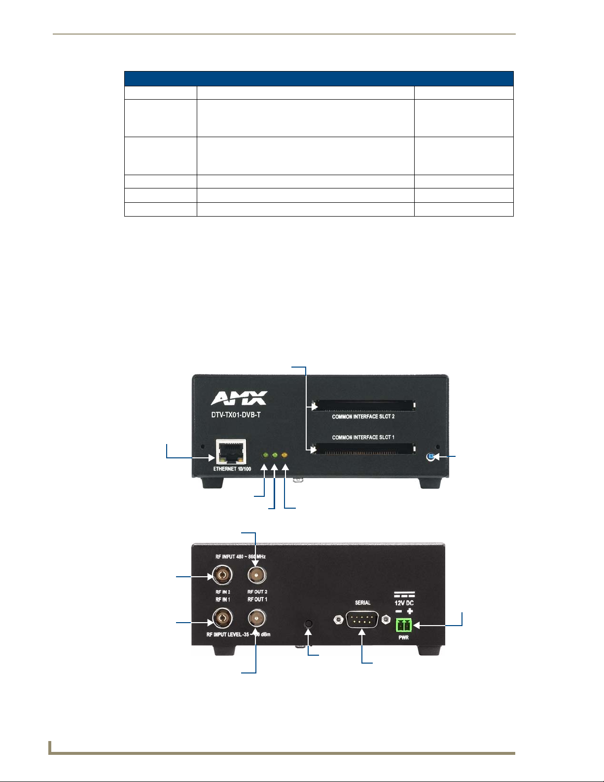
DTV-TX01-DVB-T Transmitter
The DTV-TX01-DVB-T Transmitter (FG1410-01) supports DVB-T (terrestrial) signals, and features RF 1/2
OUT output connectors to allow multiple streams for maximum channel coverage (FIG. 31).
FIG. 31
DTV-TX01-DVB-T Transmitter
Page 29
AMX TDS - Terrestrial/Satellite (Standard Definition)
21
AMX TDS (Television Delivery System)
Product Specifications
DTV-TX01-DVB-T Transmitter
Dimensions (HWD): 2.18" x 5.41" x 7.60" (5.56cm x13.74cm x 19.30cm)
Weight: 2.75 lbs (1.25 kg)
Power Requirements: • Power Consumption: 6W
• Voltage rating: nominal 12 to 13.5V DC
• Current draw at 12V: 0.5A
Tuners: 2 internal tuners
RF Input Level: • 480 ˜ 860 MHz
• -35 ˜ -50 dBm
Front Panel Components
• NETWORK Connector: Standard RJ45 connector.
• LEDs: Three LEDs indicate the status of the Transmitter:
• Streaming LED (green): Flashes if only one tuner is streaming. Steady on if both
tuners are streaming.
• Network Connectivity LED (green): Lights to indicate that the Transmitter is
connected and communicating with the network.
• Power status LED (yellow): Lights to indicate that the Transmitter is receiving
power, and is functional.
• Common Interface
Slots 1 & 2:
• RESET button: Press to reboot the Transmitter.
Rear Panel Components:
• RF INPUTs: Two TV aerial plug/Belling-Lee connectors accept incoming terrestrial signals.
• RF OUTPUTs: Two RF aerial plug/Belling-Lee connectors allow you to daisy chain
• Factory Reset Button: The recessed Factory Reset button on the rear panel allows you to perform a full
• SERIAL (RS232): DB9 serial connector for local command line interface (RS232 only).
• PWR: 2-pin mini-phoenix connector provides 12VDC power from the power supply.
Environment: • Operating Temperature: 32°F - 122°F (0°C to 50°C)
Certifications: • CE
Other AMX Equipment: • DTV-MA01 TDS Management Appliance (FG1412-01)
Dual Common Interface Slots enable the Transmitter to select encrypted channels
in cases where this is supported by the broadcaster.
Note: Before de-scrambling content using the Common Interface Slots, ensure that
you have the appropriate authority/rights to transmit the de-scrambled content on
your network.
DTV-TX01-DVB Transmitters together.
Note: There is a 3db signal loss on RF output relative to the RF input.
factory reset (resets flash and reboots the Transmitter in DHCP mode):
• Press and hold the recessed Factory Reset button while simultaneously pressing
the Reset button on the front panel.
• Continue to hold the Factory Reset button while the unit is rebooting.
• Release when the Streaming Status LED begins to flash.
Note: A 12VDC Power Supply is required (not included)
• Operating Humidity: Max. relative humidity - 85% (non-condensing)
• FCC part 15 Class A
• DTV-RX01-SD Receiver (FG1411-01)
• DTV-TX02-DVB-S Transmitter (FG1410-02)
• DTV-RK, Rack Mount Kit for DVB-T/S Transmitters (FG1410-60)
• CC-232 Serial Communication Cable (FG10-752-04)
• 12V Power Supply
Page 30

AMX TDS - Terrestrial/Satellite (Standard Definition)
22
AMX TDS (Television Delivery System)
NETWORK
RS232 Serial connector
(DB9: for local device control only)
(front)
(rear)
2-pin
PWR
connector
Factory
RF IN 2
RF IN 1
Common Interface Slots 1 & 2
Streaming status (green)
Network Connectivity status (green) Power status (yellow)
RJ45 connector
(to network)
Reset
button
Reset
button
DTV-TX02-DVB-S Transmitter
The DTV-TX02-DVB-S Transmitter (FG1410-02) supports DVB-S (satellite) signals (FIG. 32).
FIG. 32 DTV-TX02-DVB-S Transmitter
Product Specifications
DTV-TX02-DVB-S Transmitter
Dimensions (HWD): 2.18" x 5.41" x 7.60" (5.56cm x13.74cm x 19.30cm)
Weight: 2.65 lbs (1.20 kg)
Power Requirements: • Power Consumption: 4.8W
Tuners: 2 internal tuners
RF Input Level: • 950 - 2150 MHz
Front Panel Components
• NETWORK Connector: Standard RJ45 connector.
• LEDs: Three LEDs indicate the status of the Transmitter:
• Voltage rating: nominal 12 to 13.5V DC
• Current draw at 12V: 0.5A
• -35 - -55 dBm
• Streaming LED (green): Flashes if only one tuner is streaming. Steady on if both
tuners are streaming.
• Network Connectivity LED (green): Lights to indicate that the Transmitter is
connected and communicating with the network.
• Power status LED (yellow): Lights to indicate that the Transmitter is receiving
power, and is functional.
Page 31

AMX TDS - Terrestrial/Satellite (Standard Definition)
23
AMX TDS (Television Delivery System)
Cat5/5e/6 network cable
DTV-TX02-DVB-S Transmitter (Cont.)
• Common Interface
Slots 1 & 2:
• RESET button: Press to reboot the Transmitter.
Rear Panel Components:
• RF INPUTs: Two coaxial (Type F) input connectors accept incoming satellite signals.
• Factory Reset Button: The recessed Factory Reset button on the rear panel allows you to perform a full
• SERIAL (RS232): DB9 serial connector for local command line interface (RS232 only).
• PWR: 2-pin mini-phoenix connector provides 12VDC power from the power supply.
Environment: • Operating Temperature: 32°F - 122°F (0°C to 50°C)
Certifications: • CE
Other AMX Equipment: • DTV-MA01 TDS Management Appliance (FG1412-01)
Dual Common Interface Slots enable the Transmitter to select encrypted channels
in cases where this is supported by the broadcaster.
Note: Before de-scrambling content using the Common Interface Slots, ensure that
you have the appropriate authority/rights to transmit the de-scrambled content on
your network.
Note: The DVB-S unit does not provide LNB power, or a 22kHz tone. Therefore, to
change polarization or LO frequency, an LBN/22kHz injector is required at the
head-end.
factory reset (resets flash and reboots the Transmitter in DHCP mode):
• Press and hold the recessed Factory Reset button while simultaneously pressing
the Reset button on the front panel.
• Continue to hold the Factory Reset button while the unit is rebooting.
• Release when the Streaming Status LED begins to flash.
• Operating Humidity: Max. relative humidity - 85% (non-condensing)
• FCC part 15 Class A
• DTV-RX01-SD Receiver (FG1411-01)
• DTV-TX01-DVB-T Transmitter (FG1410-01)
• DTV-RK, Rack Mount Kit for DVB-T/S Transmitters (FG1410-60)
• CC-232 Serial Communication Cable (FG10-752-04)
• 12V Power Supply
DTV-TX Transmitters - Front Panel Components
The front panel components are identical on the DTV-TX01-DVB-T and DTV-TX02-DVB-S Transmitters .
Front Panel - ETHERNET 10/100 Port
The ETHERNET 10/100 (RJ45) port on the front panel provides 10/100 BaseT network connectivity via
Cat5/5e/6 network cable (FIG. 33). Refer to the Connecting the Transmitters to the Network section on
page 38 for more information.
FIG. 33
ETHERNET 10/100 Port
Page 32

AMX TDS - Terrestrial/Satellite (Standard Definition)
24
AMX TDS (Television Delivery System)
SPD - Speed LED
connection speed is 100 Mbps
and turns Off when speed is
lights (yellow) when the
L/A - Link/Activity LED
lights (green) when the
Ethernet cables are
connected and terminated
10 Mbps.
correctly.
Network Port Pinouts and Signals
The following table lists the pinouts, signals, and pairing for the NETWORK port.
RJ45 Network Port Pinouts and Signals
Pin Signals Connections Pairing Color
1 TX + 1 --------- 1 1 --------- 2 Orange-White
2 TX - 2 --------- 2 Orange
3 RX + 3 --------- 3 3 --------- 6 Green-White
4 no connection 4 --------- 4 Blue
5 no connection 5 --------- 5 Blue-White
6 RX - 6 --------- 6 Green
7 no connection 7 --------- 7 Brown-White
8 no connection 8 --------- 8 Brown
FIG. 34 diagrams the pinouts and signals for the Network RJ45 connector and cable. Note that while 568B
termination is shown in the figure, 568A can also be used, as long as both ends are terminated the same way.
FIG. 34
RJ45 wiring diagram
Consult the Network Administrator for correct cabling from the DTV-TX Transmitter
onto the network.
For remote connectivity, the Firewall may have to be configured to open port 2008 for
remote connectivity over UDP.
Ports 5000 and 5001 are required for the Transmitters as well as any ports used for
the TDS Multicast stream.
Ports 5002 and 5003 are fixed as the multicast stream output ports.
Ethernet LEDs
FIG. 35 Ethernet LEDs
Default IP Address
By default, DTV-TX Transmitters are set to DHCP.
Page 33

AMX TDS - Terrestrial/Satellite (Standard Definition)
25
AMX TDS (Television Delivery System)
Streaming Status
Network Connectivity
Power Status
Common Interface Slots
Front Panel - Status LEDs
There are three LEDs on the front panel to indicate various types of device status (FIG. 36):
FIG. 36 Status LEDs
Status LEDs
Streaming Status (green): Flashes if only one tuner is streaming. Steady on if both tuners are
streaming.
Network Connectivity Status (green): Lights to indicate that the Transmitter is connected to the network.
Power Status (yellow): Lights to indicate that the Transmitter is receiving power and is
functional.
If the LED fails to light, check your 12VDC Power connection (see the
Applying Power to the Transmitters section on page 37).
Front Panel - Common Interface Slots
DTV-TX Transmitters provide two Common Interface Slots on the front panel (FIG. 37) to enable decryption
of channels where this is supported by the broadcaster (such as in the case of Top Up TV).
FIG. 37
Only single-channel streams (as opposed to full stream mode) can be decoded with
the Common Interface Slots.
Refer to the Using Conditional Access Module (CAM) Modules section on page 39 for more information.
Common Interface Slots
Page 34

AMX TDS - Terrestrial/Satellite (Standard Definition)
26
AMX TDS (Television Delivery System)
Reset Button
RS232 Serial connector
(DB9: for local device
control only)
2-pin PWR
Factory
RF IN 2
RF OUT 2
RF IN 1
RF OUT 1
connector
RESET
button
RS232 Serial connector
(DB9: for local device
control only)
2-pin PWR
Factory
connector
RESET
button
RF IN 2
RF IN 1
DTV-TX01-DVB-T
DTV-TX02-DVB-S
Front Panel - Reset Button
Press to reboot the Transmitter (FIG. 38).
FIG. 38 Reset Button
DTV-TX Transmitters - Rear Panel Components
The rear panel components and connectors for DTV-TX01-DVB-T and DTV-TX02-DVB-S Transmitters
(FIG. 39) are described in the following sub-sections:
FIG. 39 DTV-TX01-DVB-T - Rear Panel Components
Page 35

AMX TDS - Terrestrial/Satellite (Standard Definition)
27
AMX TDS (Television Delivery System)
RF IN 1
Video is distributed via
Ethernet to DTV Receiver(s)
RF IN 2
Incoming Digital TV Signal
(up to 2 per DTV Transmitter)
Video is distributed via
Ethernet to DTV Receiver(s)
RF-1
INPUT
RF OUT 1 RF IN 1
RF OUT 1 RF IN 1
RF-2
INPUT
Coax
Coax
Rear Panel - RF IN 1 & 2
The RF IN 1 & 2 connectors accept incoming digital TV signals via a standard coaxial input.
FIG. 40 DTV-TX01-DVB-T Transmitter - RF IN 1/2
These connectors can also be used to accept incoming signals from another upstream Transmitter, in
installations with multiple Transmitters (see FIG. 41 on page 27).
Refer to the following sections for more information:
Connecting a Terrestrial Source to DTV-TX01-DVB-T Transmitters section on page 37.
Connecting a Satellite Source to DTV-TX02-DVB-S Transmitters section on page 38.
Rear Panel - RF OUT 1 & 2 (DTV-TX01-DVB-T only)
The RF OUT 1 & 2 aerial plug/Belling-Lee connectors (on the DTV-TX01-DVB-T only) allow you to daisy
chain DTV-TX01-DVB-T Transmitters together. Use these connectors to send the TV signal coming into the
RF IN 1 & 2 connectors to other downstream DTV-TX01-DVB-T Transmitters (FIG. 41).
FIG. 41 DTV-TX01-xx Transmitter
Each time an RF feed is output from a Transmitter and fed back into another
downstream Transmitter (as an RF input), the signal strength will be lower approximately a 3dB drop in signal level for each split in signal.
Rear Panel - Factory RESET Button
The recessed Factory Reset button on the rear panel allows you to perform a full factory reset (resets flash and
reboots the Transmitter in DHCP mode):
1. Press and hold the recessed Factory Reset button while simultaneously pressing the Reset button on the
front panel.
2. Continue to hold the Factory Reset button while the unit is rebooting.
3. Release when the Streaming Status LED (see FIG. 36 on page 25) begins to flash.
Page 36

AMX TDS - Terrestrial/Satellite (Standard Definition)
28
AMX TDS (Television Delivery System)
Rear Panel - SERIAL Port
The SERIAL Port on the rear panel provides a RS232 serial interface for local device control, as well as
diagnostic and troubleshooting purposes, via a standard DB9 connector.
Use a standard DB9 programming cable such as the CC-232 (FG10-752-04, not included) to
connect to a PC for Terminal control.
Supported terminal commands are listed in the Serial Commands section on page 79.
While the Serial port can be used for network setup, in most cases it is preferable to
use the Digital TV Configuration Manager to perform these tasks. Connecting the
Serial port on the DTV Transmitters is not an essential step in the installation
process.
Use hyper terminal with default serial settings to communicate with the DTV Transmitters:
Default Serial Settings
Baud Rate: 115200
Data Bits: 8
Parity: None
Stop Bits: 1
Flow Control: None
Setting the Transmitter’s IP Address via the CONSOLE Port
In most cases, all setup and configuration for both Transmitters and Receivers is done via the Digital TV
Configuration Manager. However, the Transmitter’s IP Address can also be specified using a local command
line interface, accessible via the CONSOLE (RJ12) port.
In order to configure the network settings on the Transmitters, the Transmitter must be placed in Command
mode (via the IPTVsetup serial command):
IPTVsetup<LF><CR>
Use the following command to configure the network settings:
DHCPd,i.i.i.i,gw.gw.gw.gw,nm.nm.nm.nm Sets IP details:
• d = 1: DHCP on, 0, DHCP off
• i = ip
• gw = gateway
• nm = network mask
All DTV Transmitters and Receivers must have an assigned IP Address, Network
Mask, and Gateway Address in order for the DTV system to work correctly. This
applies to units that utilize DHCP and to units that have been assigned Static IP
addresses. If you are using DHCP, verify tha t these ad dress assignments are
provided by the DHCP Server.
Rear Panel - 12VDC PWR Connector
To use the 2-pin 3.5 mm mini-Phoenix connector with a 12 VDC-compliant power supply, the incoming PWR
and GND cables from the external source must be connected to their corresponding locations on connector
(FIG. 42).
1. Insert the PWR and GND wires on the terminal end of the 2-pin 3.5 mm mini-Phoenix cable. Match the
wiring locations of the +/- on both the power supply and the terminal connector.
2. Tighten the clamp to secure the two wires. Do not tighten the screws excessively; doing so may strip the
threads and damage the connector.
3. Verify the connection of the 2-pin 3.5 mm mini-Phoenix to the external 12 VDC-compliant power supply.
Page 37

AMX TDS - Terrestrial/Satellite (Standard Definition)
29
AMX TDS (Television Delivery System)
PWR +
GND -
Transmitter
Power Supply
ETHERNET (RJ45) Port
IR Tx port
IR Rx port
CVBS digital video Out
COMPONENT video Out
SPDIF digital audio Out
Analog audio Out (L/R)
CONSOLE (RJ12) Port
Status LEDs
Reset button
Factory Reset Button (recessed)
(front)
(rear)
FIG. 42 2-pin mini-Phoenix connector wiring diagram (direct power)
For safety reasons, DTV-TX Transmitters must be connected to a MAINS socket
outlet with a protective earthing connection.
DTV-RX01-SD Receivers
The DTV-RX01-SD Receiver (FG1411-01) accepts the digital TV signals being output by the DTV
Transmitters via TDS and decodes the signals, in order to provide standard A/V connections for target display
devices (FIG. 43).
FIG. 43 DTV-RX01-SD Receiver
Product Specifications
Product Specifications - DTV-RX01-SD
Dimensions (HWD): • 1.21" x 8.55" x 3.68" (3.08cm x 21.72cm x 9.37cm)
• Can be mounted to the display device using standard VESA brackets.
Weight: 1.60 lbs (0.725 kg)
Power: PoE (Power Over Ethernet) - as a PoE-powered device, the DTV Receiver must be
used either with a PoE-enabled Network Switch, or with an PoE injector.
• PoE Class: Class 2
• Power consumption (typical usage): 3.5W
Front Panel Component
Factory Reset button
(recessed):
The recessed Factory Reset button on the front panel is used in conjunction with
the Reset pushbutton on the rear panel to perform a full factory reset of the
Receiver.
A full factory reset resets flash and reboots the unit in the factory default IP address
mode (DHCP).
See Performing a Full Factory Reset on the DTV-RX01-SD Receiver section on
page 35 for details.
Page 38

AMX TDS - Terrestrial/Satellite (Standard Definition)
30
AMX TDS (Television Delivery System)
Product Specifications - DTV-RX01-SD (Cont.)
Front Panel Components (Cont.)
CONSOLE: RJ12 connector provides local command line interface (via RS232 only).
The RS01 RS-232 Serial Transmit Cable (FG-RS01) is to be used on this port.
Note: On some units, this connector may be labelled “SERIAL”, but the
connector functions the same in either case.
IR Rx: 3.5mm stereo input port, for connection of an IR receiver to allow setup of the DTV-
RX01-SD, and for channel selection and control of local monitor volume and power.
The IR03 External IR Receiver module (FG-IR03) can be connected to this port.
Rear Panel Components
IR Tx: 3.5mm stereo output port allows one IR-controlled device (such as a local monitor)
to be controlled via an optional wired IR emitter.
The IR01 IR Emitter Module (FG-IR01) can be connected to this port.
RESET pushbutton: Press to reboot the Receiver. See the Performing a Full Factory Reset on the DTV-
RX01-SD Receiver section on page 35 for details.
Status LEDs: Three LEDs indicate the status of the Receiver:
•Power (red): Lights to indicate that the Receiver is receiving power (via PoE), and
is functional.
• Streaming (yellow): Flashes to indicate that the Receiver is receiving or sending
data from or to the master.
• Lock (green): Lights to indicate that the Receiver is locked to a transport stream,
and should be playing video/audio (if valid channel is selected).
AUDIO: RCA connectors provide audio output:
• LEFT: Analog audio Left Out
• RIGHT: Analog audio Right Out
• S/PDIF: Digital audio Out
VIDEO: RCA connectors provide video output:
• CVBS: Yellow RCA provides Composite video Out.
• RED / Pr: Component output: Pr
• BLUE / Pb: Component output: Pb
• GREEN / Y: Component output: Y
NETWORK: Standard RJ45 connector connects the Receiver to the network and provides PoE
Environment: • Operating Temperature: 35°F - 95°F (5°C - 35°C)
Certifications: • CE
Included Accessories: • DTV-RC01 Digital TV Remote Control (FG1411-70)
Other AMX Equipment: • DTV-MA01 TDS Management Appliance (FG1412-01)
power to the unit (requires PoE-enabled network switcher, or PoE injector).
• Operating Humidity: Max. relative humidity - 85% (non-condensing)
• FCC part 15 Class A
• IR03 External Infrared Receiver Module (FG-IR03)
• DTV-TX01-DVB-T Transmitter (FG1410-01)
• DTV-TX02-DVB-S Transmitter (FG1410-02)
• IR01 IR Emitter Module (FG-IR01)
• PS-POE-AF PoE Injector (FG423-80) - required only if connected to a non PoEenabled network switcher.
Page 39

AMX TDS - Terrestrial/Satellite (Standard Definition)
31
AMX TDS (Television Delivery System)
RS232 Serial Transmit cable
Feature Comparison - HD vs SD Receivers
The following table provides a summarized feature comparison for the DTV-RX01-SD (Standard Definition)
Receivers and DTV-RX02-HD (High-Definition) Receivers:
Feature Comparison - HD vs SD Receivers
Feature DTV-RX01-SD (FG1411-01) DTV-RX02-HD (FG1411-02)
Definition Standard (PAL or NTSC) High (to 1080p)
Video Decoding MPEG2 MPEG2, MPEG4pt2 and MPEG4pt10 (H.264)
Audio Decoding MPEG2 MPEG2, MPEG2layer3 (MP3), AC-3
Subtitles ETSI EN 300 743 EIA-608 (encoded line 21)
IP Stream decoding UDP UDP
PoE Yes No
IR Remote (SC-31) Yes Yes
IR Remote (SC-33) Yes No
Display Control - IR Yes No
Display Control - Serial Yes Yes
Control Menu Yes Yes
On Screen Display OSD Yes No
MAX CSE support No Yes
Refer to the DTV-RX02-HD Receivers section on page 10 for detailed information on the DTV Receivers.
All connectors are located on the rear panel of the DTV-RX01-SD, for ease of
installation and easy access.
Rear Panel - CONSOLE (RJ12) Port
The CONSOLE (RJ12) port (FIG. 44) provides access to a local command line interface via RS232, via the
RS01 RS232 Serial Transmit Cable (FG-RS01, not included).
FIG. 44 CONSOLE (RJ12) Port
See the Serial Commands section on page 79 for a listing of all supported Serial commands.
Setting the Receiver’s IP Address via the CONSOLE Port
In most cases, all setup and configuration for both Transmitters and Receivers is done via the Digital TV
Configuration Manager (see the Receiver Setup Pages section on page 66 for information).
However, the Receiver’s IP Address can also be specified using a local command line interface, accessible via
the CONSOLE (RJ12) port.
The default baud rate is 115200.
In order to configure the network settings on the Receivers, the Receiver must be placed in Command mode
(via the IPTVsetup serial command):
IPTVsetup<LF><CR>
Page 40

AMX TDS - Terrestrial/Satellite (Standard Definition)
32
AMX TDS (Television Delivery System)
IR03 IR Receiver
IR03 IR Receiver (FGIR03)
IR01 IR Emitter (FGIR01)
IR01 IR Emitter
Use the following command to configure the network settings:
DHCPd,i.i.i.i,gw.gw.gw.gw,
nm.nm.nm.nm
All DTV Transmitters and Receivers must have an assigned IP Address, Network
Mask, and Gateway Address in order for the DTV system to work correctly. This
applies to units that utilize DHCP and to units that have been assigned Static IP
addresses. If you are using DHCP, verify tha t these ad dress assignments are
provided by the DHCP Server.
Rear Panel - IR Rx Port
The IR Rx (IR Receiver) port supports remote control of connected IR devices. IR remote control requires an
IR03 External IR Receiver Module (FG-IR03, included) to receive IR commands from the remote controller
(FIG. 45).
Sets IP details:
• ip = ip
• gw = gateway
• nm = network mask
FIG. 45 IR Rx Port
The Receiver must be powered-down before connecting or removing an IR Emitter or
IR Receiver. These connections are not hot-swappable.
Connecting an IR Receiver
1. Remove power from the DTV Receiver.
2. Connect the IR03 IR Receiver cable to the IR Rx port on the DTV Receiver.
3. Run the cable and attach the IR receiver bud such that it has a clear line-of-sight with the intended remote
control device.
4. Replace power to the DTV Receiver.
Rear Panel - IR Tx Port
The IR Tx IR Transmitter port supports wired control of one connected IR device (FIG. 46).
FIG. 46 IR Tx Port
To issue IR commands to a display device, an IR01 External IR Emitter Module (FG-IR01, not included) is
installed on the display device.
Page 41

AMX TDS - Terrestrial/Satellite (Standard Definition)
33
AMX TDS (Television Delivery System)
Reset Pushbutton
Power
Streaming
Lock
RCA Stereo cable
Digital Stereo cable
Connecting an IR Emitter
1. Connect an IR01 IR Emitter cable (FG-IR01) to the IR Tx port on the DTV Receiver.
2. Run the other end of the IRTX cable to the display device and locate the IR window.
3. Attach the IR Emitter bud over the device’s IR sensor by removing the cover of the reverse side of the
Emitter and sticking it directly over the IR window.
Rear Panel - Reset Pushbutton
Press to the Reset Pushbutton on the rear panel to reboot the Receiver (FIG. 47).
FIG. 47 Reset Pushbutton
The RESET pushbutton is used in conjunction with the recessed Factory Reset
button on the front panel to perform a full factory reset of the Receiver. See the
Performing a Full Factory Reset on the DTV-RX01-SD Receiver section on page 35
for details.
Rear Panel - Status LEDs
There are three LEDs on the rear panel to indicate various types of device status (FIG. 48):
FIG. 48 Status LEDs
Power (red): Lights to indicate that the Receiver is receiving power (via PoE), and is functional.
Streaming (yellow): Flashes to indicate that the Receiver is receiving or sending data from or to the
master.
Lock (green): Lights to indicate that the Receiver is locked to a transport stream, and should be
playing video/audio (if valid channel is selected).
Rear Panel - Audio Output Connectors
The Audio Output connectors are grouped under "AUDIO" on the rear panel (FIG. 49):
FIG. 49 Audio Output Connectors
Analog: Standard red and white AUDIO RCA connectors provide analog stereo audio output
(White = Left, Red = Right).
Digital: The Black SPDIF RCA connector provides digital audio output.
Page 42

AMX TDS - Terrestrial/Satellite (Standard Definition)
34
AMX TDS (Television Delivery System)
Component Video cable
Composite Video cable
Cat5/5e/6 network cable
Rear Panel - Video Output Connectors
The Video Output connectors are grouped under "VIDEO" on the rear panel (FIG. 50):
FIG. 50 Video Output Connectors
Component: The green, red and blue COMPONENT RCA connectors provides Component
(Y/Pb/Pr) video output.
CVBS: The yellow CVBS RCA connector provides Composite video output.
Rear Panel - ETHERNET 10/100 (PoE) Port
The ETHERNET 10/100 (PoE) RJ45 port (FIG. 51) provides 10/100 BaseT network connectivity as well as
PoE (Power over Ethernet). Refer to the Connecting DTV-RX01-SD Receivers to the Network section on
page 40 for more information.
FIG. 51 ETHERNET 10/100 (PoE) Port
As a PoE-powered device, the DTV Receiver must be used either with a PoE-enabled Network Switch (such as
the NXA-ENET24PoE), or with an PoE injector (such as the PS-POE-AF).
The maximum distance that a Receiver can be mounted from the Network
Switch is 100m (328’).
Consult the Network Administrator for correct cabling from the DTV-RX01 Receiver
onto the network. For remote connectivity, the Receivers will use ports 2008, 5000,
5001, 5002 and 5003 for remote connectivity over UDP.
Default IP Address
By default, DTV Receivers are set to DHCP. See the Setting the Receiver’s IP Address via the CONSOLE
Port section on page 31.
Network Port Pinouts and Signals
Refer to the Network Port Pinouts and Signals section on page 24.
Ethernet LEDs
Refer to the Ethernet LEDs section on page 24.
Page 43

AMX TDS - Terrestrial/Satellite (Standard Definition)
35
AMX TDS (Television Delivery System)
Yellow LED
Reset pushbutton
Factory Reset button (recessed)
(front)
(rear)
Performing a Full Factory Reset on the DTV-RX01-SD Receiver
The recessed Factory Reset button on the front panel, in conjunction with the Reset pushbutton on the rear
panel (FIG. 52), allows you to perform a full factory reset of the DTV-RX01-SD Receiver. A full factory reset
resets flash and reboots the unit in the factory default IP address mode (DHCP).
FIG. 52 Performing a Full Factory Reset on the Receiver
To perform a full factory reset:
1. Press and hold the factory reset button, recessed on front panel.
2. Press and release the reset button on rear.
3. Wait until the yellow LED starts to flash and release the factory reset button.
Page 44

AMX TDS - Terrestrial/Satellite (Standard Definition)
36
AMX TDS (Television Delivery System)
PoE Network Switcher
PC
PC providing
multi-cast video
stream
Display Device
Display Device
Display Device
Display Device
Display Device
Display Device
Display Device
Display Device
Provides access to
the TDS Configuration
Manager
Video Server
providing multi-cast
video stream
Incoming TV signal
Incoming TV signal
Incoming TV signal
Incoming TV signal
DTV-RX01 Receiver
DTV-RX01 Receiver
DTV-RX01 Receiver
DTV-RX01 Receiver
DTV-RX01 Receiver
DTV-RX01 Receiver
DTV-RX01 Receiver
DTV-RX01 Receiver
DTV-TX Transmitter
DTV-TX Transmitter
DTV-TX Transmitter
DTV-TX Transmitter
DHCP Server
DTV-MA01
TDS Management Appliance
Wiring and Connections
FIG. 53 illustrates a common system installation of the AMX TDS Terrestrial/Satellite (Standard-Definition)
Systems:
FIG. 53 AMX TDS - Network Configuration
Page 45

AMX TDS - Terrestrial/Satellite (Standard Definition)
37
AMX TDS (Television Delivery System)
(rear)
Power Supply
RF IN 1:
Incoming Terrestrial
digital TV signal
RF OUT 1 (optional):
To other DVBT Transmitters
(from aerial)
Coax cable / Belling-Lee connector)
RF IN 2:
Incoming Terrestrial
digital TV signal
(from aerial)
RF OUT 2 (optional):
To other DVBT Transmitters
(rear)
Coax cable / Belling-Lee connector)
Coax cable / Belling-Lee connector)
Coax cable / Belling-Lee connector)
Installing DTV-TX-DVB Transmitters
Applying Power to the Transmitters
Each DTV-TX-DVB Transmitter receives 12 VDC power via the 2-pin captive-wire PWR connector on the
rear panel (FIG. 54).
FIG. 54 Applying Power to the Transmitters
Refer to the Rear Panel - 12VDC PWR Connector section on page 28 for details on the power connection.
Connecting TV Sources to the Transmitters
DTV-TX01-DVB-T Transmitters receive Terrestrial digital TV broadcasts, and connect to an aerial
(antenna).
DTV-TX02-DVB-S Transmitters receive Satellite digital TV broadcasts, and connect to a satellite
dish.
For DTV-TX02-DVB-S T ransmitters, LNB power and 22kHz tone need to be added at
the head-end.
Connecting a Terrestrial Source to DTV-TX01-DVB-T Transmitters
Each DTV-TX01 Transmitter has two tuners labelled RF1 and RF2, with TV aerial plug inputs (Belling-Lee
connectors) on the rear panel.
To connect the terrestrial source to the DTV-TX01, connect the TV aerial (antenna) to the RF IN 1 or RF IN 2
tuner input (FIG. 55):
FIG. 55 Connecting a Terrestrial Source to DTV-TX01-DVB-T Transmitters
This could be a connection direct from the aerial, or it could be via a splitter in order to connect to
multiple Transmitters.
Where the aerial feed is split, use an active splitter to avoid loss of signal strength.
The terrestrial aerial should be installed by a professional installer, ensuring that the
signal levels conform to the requirements listed in the Recommended Signal
Levels section on page 38.
Page 46

AMX TDS - Terrestrial/Satellite (Standard Definition)
38
AMX TDS (Television Delivery System)
Coax
RF IN 1:
Incoming Satellite
digital TV signal
(from dish)
Coax
RF IN 2:
Incoming Satellite
digital TV signal
(from dish)
(rear)
Connect to LAN
(via Network Switcher)
Cat5/5e/6
Connecting a Satellite Source to DTV-TX02-DVB-S Transmitters
Each DTV-TX02 Transmitter has two tuners labelled RF1 and RF2 with standard coax inputs on the rear
panel. To connect from the satellite dish to the DTV-TX02, use a co-axial cable with male F-type connector
(FIG. 56):
FIG. 56 Connecting a Satellite Source DTV-TX02-DVB-S Satellite Transmitters
The DTV-TX02 unit does not provide LNB power, or a 22kHz tone. Therefore, to change polarization or LO
frequency, an LBN/22kHz injector is required at the head-end.
Recommended Signal Levels
The satellite dish should be installed by a professional installer, ensuring that the signal levels conform to the
requirements listed below:
Terrestrial:
Signal level: > 45 dBìV and < 70 dBìV
Signal to noise ratio (SNR): > 26dB
Bit Error Rate (BER): < 2E-04
Satellite:
Signal to noise ratio (SNR): > 7 - 9 dB
Bit error rate (BER): < 2E-04
Connecting the Transmitters to the Network
Use the ETHERNET 10/100 Port on the front panel of the DTV-TX-DVB Transmitter to connect each
Transmitter to the network, via Cat5/5e/6 UTP network cable (FIG. 57).
FIG. 57 Connecting the Transmitters to the Network
Note that while DTV-RX01-SD Receivers require PoE for power, the DTV-TX01 Transmitters are
powered locally, and do not utilize PoE. (see the Applying Power to the Transmitters section on
page 37).
Refer to the Front Panel - ETHERNET 10/100 Port section on page 23 for details on the
ETHERNET 10/100 Port, including Pinouts and Signals information, and descriptions of the
Ethernet LEDs.
Network Configuration for the Transmitters is done via the Digital TV Configuration Manager (see
the Tran smitter Setup - Network Settingssection on page 54 for information).
By default, DTV-TX01 Transmitters are set to DHCP.
Page 47

AMX TDS - Terrestrial/Satellite (Standard Definition)
39
AMX TDS (Television Delivery System)
Slot 2 (de-scrambles signals for Tuner 2)
Slot 1 (de-scrambles signals for Tuner 1)
(front)
Using Conditional Access Module (CAM) Modules
Two Common Interface Slots on the front panel enable the Transmitter to select encrypted channels (in cases
where this is supported by the broadcaster), via appropriate Conditional Access Module (CAM) modules
(FIG. 58).
FIG. 58 Common Interface Slots
Only a single channel per stream can be decoded per tuner.
Before de-scrambling content, ensure that you have the appropriate authority/rights
to transmit the de-scrambled content on your network.
CAM modules can be inserted/removed while the Transmitter is running.
Configuring DTV-TX-DVB Transmitters
DTV Transmitters are configured via the Digital TV Configuration Manager. See the Digital TV Configuration
Manager section on page 53 for information.
Page 48

AMX TDS - Terrestrial/Satellite (Standard Definition)
40
AMX TDS (Television Delivery System)
Standard A/V connectors connect
the Receiver to the display device
PoE Network Switcher
DTV-RX01 Receiver
Cat5/5e/6
Installing DTV-RX01-SD Receivers
DTV-RX01-SD Receivers receive TDS broadcasts from DTV-TX01-DVB-T and DTV-TX02-DVB-S
Transmitters (via Ethernet), and pass the signal to the end display-device via standard A/V connectors.
DTV-RX01-SD Receivers do not connect directly to the Transmitters. Rather, they connect to Transmitters
indirectly via the LAN, using a PoE-enabled network switch.
DTV-RX01-SD Receivers receive power via PoE, therefore it is required that a PoE network
switcher (i.e. the NXA-ENET24PoE - FG2178-61 from AMX) is used to connect the Receivers to
the network.
One DTV-RX01-SD Receiver is required for each display device. The Receivers are designed to be
mounted on or near the display devices.
Each DTV-RC01 remote controller is associated with a Receiver via options in the Digital TV
Configuration Manager. See the Assigning a DTV-RC01 Remote Controller To a Specific
Receiver section on page 51 for instructions.
Connecting DTV-RX01-SD Receivers to the Network
Use standard (Cat5/5e/6 UTP) network cable to connect the DTV-RX01-SD Receivers to a PoE-enabled
network switcher.
DTV-RX01-SD Receivers feature standard A/V connectors to deliver the incoming TV signal to the display
device (FIG. 59).
FIG. 59 Connecting DTV-TX01 Transmitters to DTV-RX01-SD Receivers
Configuring DTV-RX01-SD Receivers
The Receivers are configured via the Digital TV Configuration Manager. See the Receiver Setup Pages section
on page 66 for information.
Page 49

DTV-MA01 TDS Management Appliance
41
AMX TDS (Television Delivery System)
Status light (surrounds the Power Switch)
Power Switch
USB Ports
Serial Port
Power
SVGA Video Out
HDMI Video Out
Ethernet Port
USB Ports
Audio Out
(front)
(rear)
DTV-MA01 TDS Management Appliance
Overview
The DTV-MA01 TDS Management Appliance (FG1412-01) manages television distribution in a TDS system
(FIG. 60).
FIG. 60 DTV-MA01 TDS Management Appliance
Product Specifications - DTV-MA01 TDS Management Appliance
Dimensions (HWD): 6.54" x 1.89" x 6.46" (16.6 cm x 4.8 cm x 16.4 cm)
Weight: 2.85 lbs (1.3 kg)
Power • 100-240VAC, 1.5A, 50/60Hz
Environmental: • Environment Operating Temperature: 0 ~ 50°C (32 ~ 122°F)
Enclosure: Enclosure SECC with black matte finish
Operating System: POSReady 2009
Front Panel Components
Status: Blue LED indicates power status and hard drive activity
Power Switch: Turns power on/off.
USB Ports: 2 Type-B USB 2.0 Ports for connecting USB mouse and keyboard.
• 90W (20V, 4.5A) AC Adapter
• Storage Temperature: -30 ~ 60ºC (-22 ~ 140ºF)
• Relative Humidity : 90% RH (45°C non-Condensing)
Note: This is a "soft switch": flipping the switch while the Player is running issues a
shutdown request.
Note: The Player is designed to be used without a keyboard and mouse; they are
only required for initial configuration and maintenance.
Page 50

DTV-MA01 TDS Management Appliance
42
AMX TDS (Television Delivery System)
12 VDC Power Connector
Product Specifications - DTV-MA01 TDS Management Appliance (Cont.)
Rear Panel Components
Power Connector: • 90W (20V,4.5A) AC Adapter
USB Ports: 4 Type-B USB 2.0 Ports.
Ethernet Port: RJ-45 Ethernet port provides Gigabit Ethernet communication between the Player
Audio Out: Provides stereo audio output
Serial Port: Provides serial control over devices which support RS232 commands
HDMI Video Out : Provides HDMI video output to the display, via an HDMI cable
VGA Video Out: Provides analog RGBHV video output to the display
e-SATA: Reserved for future use
Certifications CE, FCC, UL, CB
Included Accessories One power adaptor
Other AMX
Equipment:
• Input Voltage AC 100-240V
Note: Isolate IT Power System Connection.
and the LAN.
Note: The Audio in (blue) and Microphone (red) connectors are not used.
• DTV-RX01-SD Receiver (FG1411-01)
• DTV-TX01-DVB-T Transmitter (FG1410-01)
• DTV-TX02-DVB-S Transmitter (FG1410-02)
• DTV-RX02-HD Receiver (FG1411-02)
• DTV-TX03-US Transmitter (FG1410-03)
Rear Panel Components
12 VDC Power Connector
Connect the power adapter to the unit, and plug the power adapter into an AC power outlet (FIG. 61).
FIG. 61
Use ONLY the power adapter supplied with the DTV-MA01. Otherwise, the unit may
be damaged.
12 VDC Power Connector
Page 51

DTV-MA01 TDS Management Appliance
43
AMX TDS (Television Delivery System)
HDMI Video OutputVGA Video Output
10/100 Network Port
Video Output Connectors
The VGA and HDMI Video Output connectors are located on the rear panel (FIG. 62):
FIG. 62 Video Output Connectors
VGA: The VGA connector provides analog RGBHV.
HDMI: The HDMI connector provides HDMI video output.
10/100 Network Port
The 10/100 (Ethernet RJ45) port on the front panel provides 10/100 BaseT network connectivity via
Cat5/5e/6 network cable (FIG. 63).
Refer to the AMX TDS Installation Overview section on page 47 for more information.
FIG. 63 10/100 Network Port
10/100 Network Port Pinouts and Signals
The following table lists the pinouts, signals, and pairing for the 10/100 Network port.
10/100 Port Pinouts and Signals
Pin Signals Connections Pairing Color
1 TX + 1 --------- 1 1 --------- 2 Orange-White
2 TX - 2 --------- 2 Orange
3 RX + 3 --------- 3 3 --------- 6 Green-White
4 no connection 4 --------- 4 Blue
5 no connection 5 --------- 5 Blue-White
6 RX - 6 --------- 6 Green
7 no connection 7 --------- 7 Brown-White
8 no connection 8 --------- 8 Brown
Page 52

DTV-MA01 TDS Management Appliance
44
AMX TDS (Television Delivery System)
SPD - Speed LED
connection speed is 100 Mbps
and turns Off when speed is
lights (yellow) when the
L/A - Link/Activity LED
lights (green) when the
Ethernet cables are
connected and terminated
10 Mbps.
correctly.
Analog Audio Output
FIG. 64 diagrams the pinouts and signals for the 10/100 Port RJ45 connector and cable. Note that while 568B
termination is shown in the figure, 568A can also be used, as long as both ends are terminated the same way.
FIG. 64 RJ45 wiring diagram
Consult the Network Administrator for correct cabling from the DTV-MA01 onto the network.
For remote connectivity, the Firewall may have to be configured to open port 2008 for remote
connectivity over UDP.
Ports 5000 and 5001 are required for the Transmitters as well as any ports used for the TDS
Multicast stream.
Ports 5002 and 5003 are fixed as the multicast stream output ports.
Ethernet LEDs
FIG. 65 Ethernet LEDs
Default IP Address
By default, the DTV-MA01 is set to DHCP.
The DTV-MA01 must be set to a static IP address, or have the DHCP server set
up to always give it the same IP address. Automatic re-assignment of the IP
address via DHCP may cause communication issues with the TDS system. If the
DTV-MA01 is assigned a new IP address, then all TX and RX units in the system
must be rebooted.
Network Switch Requirements
The DTV-MA01 requires a Layer 3 Gigabit Switch with multicast support, IGMP Querier/Snooping and PIM.
Audio Output Connector
The green 1/8" stereo connector provides analog audio output (FIG. 66). Note that the Audio in (blue) and
Microphone (red) connectors are not used.
FIG. 66 Analog Audio Output
Page 53

DTV-RC01 Digital TV Remote Controller
45
AMX TDS (Television Delivery System)
AMX - Displays user-defined Control Menu
MENU - Displays menu options (EPG, sub-titles, language)
GUIDE - Displays the EPG (program list)
EXIT - Exits any on-screen displays
INFO - Access detailed program information
F1 - user-programmable (via NetLinx code)
OFF - Powers off/on the local display device
MUTE - Mutes the audio
SEL - Select the highlighted option on-screen
Red - Page Up (EPG)
Green - Page Down (EPG)
Yellow - user-programmable (via NetLinx code)
Blue - user-programmable (via NetLinx code)
(#)0-9 - Enter Channel numbers
VOL - Up/Down arrows adjust volume on display device
CH - Up/Down arrows change channels on display device
DTV-RC01 Digital TV Remote Controller
Overview
The DTV-RC01 Digital TV Remote Controller (FG1411-70) allows the user to change the channel and
navigate the available channels (FIG. 67).
FIG. 67 DTV-RC01 Digital TV Remote Controller
Product Specifications - DTV-RC01 Remote Controller
Dimensions (HWD): • 3 5/16" x 2 1/8" x 1/4" (3.31" x 2.13" x 0.25")
• 8.41cm x 5.39cm x 0.63 cm
Battery: CR 2032 lithium battery
Caution: Danger of explosion if battery is incorrectly replaced.
Replace only with the same or equivalent type.
Rated Supply Voltage: 3Vdc. / CR2032
Each DTV-RC01 is associated with a single DTV-RX02-HD Receiver, via options in the Receiver Setup - IR
Settings page. See the Assigning a DTV-RC01 Remote Contr oller To a Specific Receiver section on page 51 for
information.
The DTV-RC01 controls the DTV-RX02-HD Receiver via its built-in IR Receiver, or optionally via an
External IR Receiver (60-1411-01, not included).
When installing the DTV Receiver, be sure to position the unit so that IR signals from
the DTV-RC01 can reach the IR Receiver.
The button functions of the DTV-RC01 are described below:
DTV-RC01 Digital TV Remote Controller - Button Functions
• AMX: Press to access a user-definable (10x10) Control Menu.
• MENU: Press to access a sub-menu that allows access to the EPG (programming
guide), Subtitles and Audio Language settings.
These options allow the selection of the configured settings made in the TDS
Configuration Menu, and apply only to the Receiver associated with the
DTV-RC01.
Page 54

DTV-RC01 Digital TV Remote Controller
46
AMX TDS (Television Delivery System)
DTV-RC01 Digital TV Remote Controller - Button Functions (Cont.)
• GUIDE: Displays the EPG (programming guide).
• EXIT: Press to exit any on-screen display and return to the current program.
• SEL: (Select) - Selects the highlighted option on the screen.
• Arrows (up/down, left/right): Press to navigate within any on-screen menus or displays.
• INFO: Press to access detailed programming information on the current program.
• 1, 2, 3, 4, 5, 6, 7, 8, 9, 0 Press to enter channel numbers.
• F1: This button is user-programmable via NetLinx code.
• OFF: Press to power the local display off and on (via NetLinx Code).
• MUTE: Press to mute the audio. Press again to un-mute (via NetLinx Code).
• VOL (up/down): Press to adjust the volume up/down on the local display (via NetLinx Code).
• CH (up/down): Press to change the channel up/down on the local display (via NetLinx Code).
• Red: Press for "Page Up" in the EPG (Programming Guide).
• Green: Press for "Page Down" in the EPG (Programming Guide).
• Yellow: This button is user-programmable via NetLinx code.
• Blue: This button is user-programmable via NetLinx code.
Refer to the Assigning a DTV-RC01 Remote Controller To a Specific Receiver section on page 51 for
instructions on associating the DTV-RC01 to a specific Receiver in the system.
Page 55

47
AMX TDS (Television Delivery System)
AMX TDS Installation Overview
Connect a VGA Monitor
Connect USB Keyboard
Connect USB Mouse
Connect Power Cable
Overview
This section gives a brief overview of the steps required to get the AMX TDS system up and running. All
configuration is done via options in the Digital TV Configuration Manager web console.
The DTV-MA01 requires Layer 3 switching. Therefore, a Layer 3 Network Switch
(also referred to as a "Multilayer Switch") is required to operate properly.
1) Set a Static IP Address for the DTV-MA01
The first step is to make the basic connections to the DTV-MA01 in order to set a Static IP Address for the
unit. This will allow you to add the DTV-MA01 to a LAN for subsequent configuration and control:
The DTV-MA01 must be set to a static IP address, or have the DHCP server set
up to always give it the same IP address. Automatic re-assignment of the IP
address via DHCP may cause communication issues with the TDS system. If the
DTV-MA01 is assigned a new IP address, then all TX and RX units in the system
must be rebooted.
1. Connect a USB Keyboard and mouse to any two USB Ports on the unit (USB Ports are available on both
the front and rear panels - see FIG. 68).
AMX TDS Installation Overview
FIG. 68 DTV-MA01 (rear panel)
By default, the DTV-MA01 recognizes all USB keyboards as UK-Style Keyboards.
There are subtle differences in the key layouts between UK and US keyboards.
Therefore, if you are using a US style keyboard to enter data, verify that you are
getting the expected results as you type. This should not be an issue if you are only
entering basic login credentials and IP address information.
2. Connect a monitor to the SVGA (or HDMI) Video Output on the rear panel.
3. Plug in the provided power cable.
4. Press the Power Switch on the front panel to power the unit on (FIG. 69).
Page 56

AMX TDS Installation Overview
48
AMX TDS (Television Delivery System)
Power Switch
FIG. 69 DTV-MA01 (front panel)
5. Once the unit is powered up, you will be logged in automatically, using the default User Name and
Password:
Default User Name: "amxdtv"
Default Password: "admin" (case-sensitive)
6. Either via the Control Panel (Network Connections) or a Terminal session, set a static TCP/IP Address for
the DTV-MA01 (make a note of the address, you’ll need it in the next step).
If your Network Administrator does not allow static TCP/IP addressing, they will have
to setup the DHCP server to always give the DTV-MA01 the same IP address.
2) Access the TDS Configuration Pages
1. Power-up the DTV-MA01.
2. On any PC that has access to the LAN to which the DTV-MA01 is connected, open a web browser and
enter the following default URL to access the TDS Configuration Pages (on the DTV-MA01):
http://<IP Address assigned to the DTV-MA01>:8080/TDS/web/TxNetworkPage.xml
3. Press enter to be prompted for the default User Name and Password for the DTV-MA01:
Default User Name: "amxdtv"
Default Password: "admin" (case-sensitive)
The User Name and Password can be changed via options in the System Setup page
(in the Digital TV Configuration Manager). See the System Setup Page section on
page 75 for details.
4. Press OK to proceed to the built-in Web Console called the "Digital TV Configuration Manager".
The Digital TV Configuration Manager allows you to configure the Receiver and all Transmitters in the TDS
solution via a web browser on any PC that has access to the LAN to which the DTV-MA01 is connected.
Refer to the Digital TV Configuration Manager section on page 53 for information on each of the
Configuration Pages.
3) Configure the NetLinx Master for AMX TDS
While it is not a requirement of the TDS System, many installations utilize a NetLinx Master (in conjunction
with one or more touch panels) for system control.
By utilizing the NetLinx AMX TDS Module (available to download from www.amx.com) on the Master, the
TDS Transmitters and Receivers can interface with NetLinx code to perform various functions (such as
controlling screens via Serial) which can't be done through the web pages described in this document.
In order to use a NetLinx Master with the TDS system, two steps must be taken to prepare the Master (both
require the NetLinx Studio application):
1. The AMX TDS Duet Module (.JAR file) must be loaded on the Master.
2. The Master’s Source Code file must be modified slightly and reloaded to the Master.
Page 57

AMX TDS Installation Overview
49
AMX TDS (Television Delivery System)
Load the AMX TDS Module on the NetLinx Master
Download the Duet Module file - AMX_DIGITAL_TV_Server_dr00_01_00.JAR from
1.
www.amx.com.
2. Use the File Transfer utility in NetLinx Studio to transfer the JAR file to the Master.
Refer to the NetLinx Studio online help for instructions on transferring files to system devices.
Modify the Master’s Source Code
To run the AMX TDS Duet Module on the NetLinx Master, the following changes must be made to the
Master’s Source Code file:
DEFINE_START
DEFINE_MODULE 'AMX_DIGITAL_TV_Server_dr00_01_00' mdl1(vdvMAIN,vdvMAIN)
....
DEFINE_EVENT
DATA_EVENT[vdvMAIN]
{
ONLINE:
{
SEND_COMMAND vdvMAIN,"'PROPERTY-IP_Address,192.168.60.128'"
// Change to the IP address of the DTV-MA01
SEND_COMMAND vdvMAIN,"'PROPERTY-Port,2008'"
....
Refer to the TDS Module documentation for more detailed instructions on its use.
4) Install System Hardware
1. Install the Transmitters - refer to the following sections of this document for information:
Installing DTV-TX03-US Transmitters on page 16.
Installing DTV-TX-DVB Transmitters on page 37.
2. Install the Receivers - refer to the following sections of this document for information:
Installing DTV-RX02-HD Receiv er s on page 17.
Installing DTV-RX01-SD Receivers on page 40
When installing the DTV Receiver, be sure to position the unit so that IR signals from
the DTV-RC01 can reach the IR Receiver.
5) Configure the Transmitter(s)
The Tuner in each Transmitter must be configured individually. Configure the Tuner in each Transmitter via
options in the Transmitter Setup pages. The basic steps outlined below apply to each Transmitter in the system:
1. Open the Digital TV Configuration Manager (see the Accessing the Digital TV Configuration
Manager section on page 53).
2. Click the Tx Setup command button to open the Transmitter Setup (Network Settings) page (see the
Transmitter Setup Pagessection on page 54).
The Transmitters are listed under Manage Unit in the Transmitter Setup - Network Settings page,
each one indicated by it’s MAC address. The MAC address for each Transmitter is printed on a
label located on the bottom panel of the device.
If you do not see the installed Transmitters indicated in this list, refresh your browser window.
Page 58

AMX TDS Installation Overview
50
AMX TDS (Television Delivery System)
After booting up a Tx (or Rx), it must first be allocated an IP address (if DHCP
enabled) before appearing in the device list. Depending on the Network, this may
take a couple of minutes.
3. Rename each Transmitter, so that you can identify them easily in the future.
a. Select a Transmitter in the Manage Unit list.
b. Enter a new name for the selected Transmitter in the Unit Name text field.
c. Click Update.
4. Scan for channels on the tuner in each Transmitter:
a. Select Tuner A Setup to access the Tuner A Setup page.
The Tuner B Setup option on this page is not used.
b. Select the Tuner Type (see page 56).
c. Click Scan. The scan process can take several minutes to complete, depending on the number of
frequencies, and number of channels per frequency being scanned. The following page is displayed
during the scan process (FIG. 70):
FIG. 70 Manage Transmitters - Channel Scan In Progress
d. Click Refresh.
If the scan is not yet complete, Refresh simply returns you to the Scanning In Progress page.
When the scan is compete, Refresh to view the results of the scan, in the form of a listing of
Channels found on the scanned frequency.
5. Select the channels that you want to enable.
You can manually enable up to five channels from the same transport stream.
Select Full Stream to enable all channels from a transport stream.
Page 59

AMX TDS Installation Overview
51
AMX TDS (Television Delivery System)
6. Assign a unique IP (multicast) address to the Tuner:
a. Select Tuner A Setup to access the Tuner A Setup page.
b. Enter a unique IP address for Tuner A in the Tuner Output/IP Address field, and click Save.
A IPv4 multicast address should be used, ranging from 224.0.0.0 to
239.255.255.255. Avoid any reserved addresses.
6) Configure the Receiver(s)
The basic steps outlined below apply to each Receiver in the system.
1. Click the Rx Setup command button to open the Receiver Setup (Network Settings) page (see the
Receiver Setup Pages section on page 66).
The Receivers are listed under Manage Unit in the Receiver Setup - Network Settings page, each
one indicated by it’s MAC address. The MAC address for each Receiver is printed on a label
located on the bottom panel of the device.
If you do not see the installed Receivers indicated in this list, refresh your browser window.
After booting up a Rx (or Tx), it must first be allocated an IP address (if DHCP
enabled) before appearing in the device list. Depending on the Network, this may
take a couple of minutes.
2. Rename each Receiver, so that you can identify them easily in the future.
a. Select a Receiver in the Manage Unit list.
b. Enter a new name for the selected Receiver in the Unit Name text field.
c. Click Update.
3. Enable Channels on the selected Receiver:
a. Click Channel Setup to open the Receiver Setup - Channel Settings page.
b. Select the channels that you want to receive on the selected Receiver.
Select All Units to apply the channel selection on this page to all Receivers in the system.
c. Click Save.
Scaling and Centering the Picture
If the picture needs to be scaled or centered:
1. Disconnect the Receiver from the network and reboot.
2. Press MENU on the remote to display the menu page on the monitor.
3. The Player Setup options allow the user to adjust display scale and position.
Assigning a DTV-RC01 Remote Controller To a Specific Receiver
In the Digital TV Configuration Manager (see the Digital TV Configuration Manager section on
1.
page 53), enter a 2-digit numeral/character combo (any combination of 0-9 and A-F), in the Remote
Control Number field of the Receiver Setup - Output Settings page (FIG. 71).
FIG. 71 Receiver Setup - IR Settings
The default Remote Control Number for DTV-RC01 remote controllers is 6E.
See the Receiver Setup - Output Settings (DTV-RX02-HD) section on page 69 for
more information.
2. Click Save to load the new remote control address into the Receiver.
Page 60

AMX TDS Installation Overview
52
AMX TDS (Television Delivery System)
A B
CDEF
3. Press and hold the SEL and OFF buttons for 4 seconds.
4. Enter the Remote Control Number number by pressing buttons on the DTV-RC01. Refer to FIG. 72 for
entering letters (A-F):
FIG. 72 DTV-RC01 - Letter keys
5. Press the SEL button to save the number.
At this point, you should be able to use the DTV-RC01 to control the associated Receiver and
Repeat this process to assign a unique Remote Control Number to each DTV-RC01/Receiver pair,
Refer to the DTV-RC01 Digital TV Remote Controller section on page 45 for details on using the
connected display device.
DTV-RC01.
To return to the default remote control address (6E), press and hold the SEL and
GUIDE buttons for 4 seconds.
Page 61

53
AMX TDS (Television Delivery System)
Digital TV Configuration Manager
Command Buttons provide access to the main configuration pages
Overview
The DTV-MA01 TDS Management Appliance features a built-in web console called the Digital TV
Configuration Manager. The Digital TV Configuration Manager allows you to configure the Receiver and all
Transmitters in the TDS solution via a web browser on any PC that has access to the DTV-MA01 in the TDS
system.
These instructions assume that the TDS System has been installed, and that the DTV-MA01 and a PC is
connected to the LAN. Refer to the AMX TDS Installation Overviewsection on page 47 for instructions on
connecting the DTV-MA01 to the network and installing the TDS System.
Accessing the Digital TV Configuration Manager
1. On any PC that has access to the LAN to which the DTV-MA01 is connected, open a web browser and
enter the following default URL to access the TDS Configuration Pages (on the DTV-MA01):
http://<IP Address assigned to the DTV-MA01>:8080/TDS/web/TxNetworkPage.xml
2. Press enter to be prompted for the default User Name and Password for the DTV-MA01:
Default User Name: "amxdtv" (case-sensitive)
Default Password: "admin" (case-sensitive)
Digital TV Configuration Manager
The User Name and Password can be changed via options in the System Setup page
(in the Digital TV Configuration Manager). See the System Setup Page section on
page 75 for details.
3. Press OK to proceed to the Digital TV Configuration Manager. The initial view is of the Transmitter
Setup page (FIG. 73).
FIG. 73 Transmitter Setup -Network Setup
The command buttons along the top of the page provide access to the main areas of the Digital TV
Configuration Manager:
Tx Setup - Click to configure DTV Transmitters (see the Transmitter Setup Pages section on
page 54).
Rx Setup - Click to configure DTV Receivers (see the Receiver Setup Pages section on page 66).
External AV - Click to add and configure external AV devices to be included in the TDS system
(see the External AV Setup Page section on page 74).
System Setup - Click to configure the TDS System (see the System Setup Page section on
page 75).
Page 62

Digital TV Configuration Manager
54
AMX TDS (Television Delivery System)
Click to refresh the Tx device list
Click to save the Network Settings for the selected Transmitter
The links directly below the three command buttons (Network Setting s, Channel Setup, IR Settings, Firmware
Upgrade & Diagnostics Logs) provide access to configuration options specific to the current area of the
Configuration Manager, as described in the following sections.
Transmitter Setup Pages
Click the Tx Setup command button (FIG. 74) to access the Transmitter Setup pages described in the
following sub-sections.
FIG. 74 Tx Setup command button
By default, DTV Transmitters are set to DHCP.
Transmitter Setup - Network Settings
Select Network Settings in the Manage Transmitters page to access the options shown in FIG. 75:
FIG. 75 Transmitter Setup -Network Setup
The options on the Transmitter Setup - Network Settings page include:
Transmitter Setup - Network Settings
Manage Unit
• Device List: The Manage Unit window displays a list of all DTV Transmitters connected to
• Refresh List: Click to refresh the Transmitters list (in the Manage Unit window).:
the Master.
Page 63

Digital TV Configuration Manager
55
AMX TDS (Television Delivery System)
Transmitter Setup - Network Settings (Cont.)
Network Settings
• Unit Name: Displays the name currently assigned to the selected Transmitter.
Note: By default, they are named according to their MAC Addresses, with the
prefix "Tx -" to indicate Transmitters.
To change the Unit Name, type the new name here.
• DHCP / Static IP: Select either DHCP (default setting), or Static IP.
By default, DTV Transmitters are set to DHCP.
If Static IP is selected, the following IP address fields are enabled, and
required:
IP Address: Assign a valid IP Address for the Transmitter (Static IP only).
Subnet Mask: Assign a valid Subnet Mask for the Transmitter (Static IP
only).
Gateway: This display-only field provides the Gateway Address of the
selected Transmitter.
MAC Address: This display-only field provides the MAC Address of the
selected Transmitter.
Note: All DTV Transmitters and Receivers must have an assigned IP Address,
Network Mask, and Gateway Address in order for the DTV system to work
correctly. This applies to units that utilize DHCP and to units that have been
assigned Static IP addresses. If you are using DHCP, verify that these address
assignments are provided by the DHCP Server.
• Update: Click to save the Network Settings for the selected Transmitter.
Unit Status
• Current Status: Indicates that the selected Transmitter is online or offline.
• Send Poll: Click to send a poll to the selected Transmitter to see if it is online.
• Refresh: Click to refresh the unit status.
Reset to Default
• Reset unit to factory default: Click to reset the Network Settings for selected Transmitter to DHCP.
Page 64

Digital TV Configuration Manager
56
AMX TDS (Television Delivery System)
Transmitter Setup - Tuner Setup (DTV-TX03-US)
With a DTV-TX03-US transmitter selected in the Manage Unit list, select Tuner A Setup in the Manage
Transmitters page to access the options shown in . The options on this page are specific to
DTV-TX03-US (high-definition) transmitters.
FIG. 76 DTV-TX03-US Transmitter Setup - Tuner Setup
The Manage Unit window displays a list of all DTV Transmitters found to be connected to the Master. Click
Refresh List to refresh the list.
Each DTV Transmitter contains one internal tuner (the Tuner B Setup option is not used).
Each Tuner can handle a single (frequency) stream, with a maximum total of five channels per
stream, unless Full Stream is selected.
Transmitter Setup - Tuner Setup (DTV-TX03-US)
Manage Unit
• Device List: The Manage Unit window displays a list of all DTV Transmitters connected to
• Refresh List: Click to refresh the Transmitters list (in the Manage Unit window).:
Tuner A/B Channels - ATSC/QAM
• Master Tuner IP Address: Enter the output (IP) address for the multicast address.
• Tuner Type: Select the type of tuner (ATSC, QAM64 or QAM256) from the drop-down list.
• Streaming Priority This read-only field indicates the priority of the following streams:
• Scan: Click to initiate a scan for transponders, based on the parameters entered.
the Master.
Port: This read-only field indicates the output port used by the Transmitter for
streaming output.
1) Full Stream using Master IP address
2) Individual channel to Individual IP address
3) Selectable channels using Master Tuner IP address
Note: This scan may take several minutes to complete, depending on the
number of frequencies, and the number of channels present
Page 65

Digital TV Configuration Manager
57
AMX TDS (Television Delivery System)
Transmitter Setup - Tuner Setup (DTV-TX03-US)
Stream
Each stream detected by the Tuner is displayed in this area. The example screen shown in FIG. 76 on page 56
indicates only four Streams, but (depending on the provider) there may be any number of Streams available.
Each Stream indicated here provides the following information and options:
• Stream Number: This read-only field indicates the Stream Number used by the selected
• Full Stream: Select this option to multicast all channels within the transport stream.
• Channel List: The main window on this page provides a listing of all channels detected by the
Save Click to save all changes made on this page.
Re-Stream: Click to re-start the stream for the selected channel(s).
Disable all Channels: Click to disable (and de-select) all channels from all streams.
Transmitter.
"Full Stream" is a technology that uses a hardware accelerated filtering method
to improve the performance and visual quality of streaming video playback.
Note: If streaming has been changed between Full Stream and individual
channel selection the unit will automatically reboot.
Transmitter, complete with the following information and options:
• Ch. No: Channel number. To change channel numbers, click and type
directly into this text field.
• Ch. Name: Channel name. To change channel names, click and type
directly into this text field.
• Frequency: Channel frequency (read-only)
• Strength: Strength of channel’s signal (0 - 255, read-only).
Note: For best results, only stream channels with a Strength
rating of 201-255.
• Enabled: Click these check boxes to enable each listed channel.
Up to 5 individual channels can be selected per stream; one
stream for each of the two Tuners.
Note: If streaming has been changed between full stream and individual
channel selection the unit will automatically reboot.
Note: If the tuner unit is currently streaming, the unit may reboot depending on
the stream type.
Page 66

Digital TV Configuration Manager
58
AMX TDS (Television Delivery System)
Transmitter Setup - Tuner Setup (DTV-TX01-DVB-T)
With a DTV-TX01-DVB-T transmitter selected in the Manage Unit list, select Tuner A Setup in the Manage
Transmitters page to access the options shown in . The options on this page are specific to
DTV-TX01-DVB-T (terrestrial) transmitters.
FIG. 77 DTV-TX01-DVB-T Transmitter Setup - Tuner Setup
Select Tune r B Setup in the Manage Transmitters page to access Tuner B Setup
options. The configuration options are identical for both Tuners. The only difference is
that the changes made are applied to Tuner B.
Page 67

Digital TV Configuration Manager
59
AMX TDS (Television Delivery System)
The Manage Unit window displays a list of all DTV Transmitters found to be connected to the Master. Click
Refresh to refresh the list.
Each DTV Transmitter contains two internal tuners (A & B).
Each Tuner can handle a single (frequency) stream, with a maximum total of five channels per
stream, unless Full Stream is selected.
Transmitter Setup - Tuner Setup (DTV-TX01-DVB-T)
Manage Unit
• Device List: The Manage Unit window displays a list of all DTV Transmitters connected to
the Master. Click Refresh to refresh the list.
• Refresh: Click to refresh the Transmitters list (in the Manage Unit window).:
Tuner A/B Channels - DVB-T
• Tuner Output IP Address: Enter the output (IP) address for the multicast address.
Port: This read-only field indicates the output port used by the Transmitter for
streaming output.
• Tuner Region: Select the region (UK, Europe, Australia, China, USA, Canada or Japan) in
which this Tuner will be used from the drop-down list.
• Number of PIDs Used: Each channel uses some number of PIDs to deliver various aspects of the
stream. This read-only field indicates the number of PIDs used by the selected
channels.
• The maximum number of PIDs allowed for non-Full Stream is 22.
• This value only applies to individually selected channels (as opposed to Full
Stream).
Note: Always refresh the Number of PIDs Used value after selecting channels
(via the Refresh button), to ensure that the number of PIDs used by the selected
channels has not exceeded 22.
• Scan: Click to initiate a scan for transponders, based on the parameters entered.
Note: This scan may take several minutes to complete, depending on the
number of frequencies, and the number of channels present
• Refresh: Click to refresh the read-only Number of PIDs Used value (see above), after
selecting or de-selecting channels.
Stream
Each stream detected by the Tuner is displayed in this area. Depending on the provider, there may be any
number of Streams available. Each Stream indicated here provides the following information and options:
• Stream Number: This read-only field indicates the Stream Number used by the selected
Transmitter.
• Full Stream: Select this option to multicast all channels within the transport stream.
"Full Stream" is a technology that uses a hardware accelerated filtering method
to improve the performance and visual quality of streaming video playback.
Note: If streaming has been changed between Full Stream and individual
channel selection the unit will automatically reboot.
Page 68

Digital TV Configuration Manager
60
AMX TDS (Television Delivery System)
Transmitter Setup - Tuner Setup (DTV-TX01-DVB-T - Cont.)
• Channel List: The main window on this page provides a listing of all channels detected by the
Save Click to save all changes made on this page.
Re-Stream: Click to re-start the stream for the selected channel(s).
Disable all Channels: Click to disable (and de-select) all channels from all streams.
Transmitter, complete with the following information and options:
• Ch. No: Channel number. To change channel numbers, click and type
directly into this text field.
• Ch. Name: Channel name. To change channel names, click and type
directly into this text field.
• Frequency: Channel frequency (read-only)
• Strength: Strength of channel’s signal (0 - 255, read-only)
• Encrypted: Click these check boxes for all channels that are encrypted. If
Encrypted is selected, the Transmitter will decode the signal.
Note: If an encrypted channel is selected, then no other
channels can be specified.
• Enabled: Click these check boxes to enable each listed channel.
Up to 5 individual channels can be selected per stream; one
stream for each of the two Tuners.
Note: While you can enable up to five channels, there is a limit
of up to 22 PIDs per stream. Theoretically, it is possible to
select less than five channels and still surpass the maximum
number of PIDs allowed (for example four channels selected
with six PIDs each).
Therefore, always refresh the "Number of PIDs Used" value
after selecting channels (via the Refresh button next to that
field) to ensure that all selected channels will in fact be
enabled.
Note: If streaming has been changed between full stream and individual
channel selection the unit will automatically reboot.
Note: If the tuner unit is currently streaming, the unit may reboot depending on
the stream type.
Page 69

Digital TV Configuration Manager
61
AMX TDS (Television Delivery System)
Transmitter Setup - Tuner Setup (DTV-TX02-DVB-S)
With a DTV-TX02-DVB-S transmitter selected in the Manage Unit list, select Tuner A Setup in the Manage
Transmitters page to access the options shown in . The options on this page are specific to
DTV-TX02-DVB-S (satellite) transmitters
FIG. 78 DTV-TX02-DVB-S Transmitter Setup - Tuner Setup
Select Tuner B Setup in the Manage Transmitters page to access Tuner B Setup
options. The options for Tuner B are identical to those provided for Tuner A, with one
exception: Tuner B does not provide an option for Full Stream. Any changes made
on the Tuner B Setup page are applied to Tuner B.
The Manage Unit window displays a list of all DTV Transmitters found to be connected to the Master. Click
Refresh to refresh the list.
Each DTV Transmitter contains two internal tuners (A & B).
Tuner A can handle a single (frequency) stream, with a maximum total of five channels per stream,
unless Full Stream is selected.
Tuner B can output up to five channels, but does not support Full Stream.
Page 70

Digital TV Configuration Manager
62
AMX TDS (Television Delivery System)
Transmitter Setup - Tuner Setup (DTV-TX02-DVB-S)
Manage Unit
• Device List: The Manage Unit window displays a list of all DTV Transmitters connected to
• Refresh: Click to refresh the Transmitters list (in the Manage Unit window).:
Tuner A/B Channels - DVB-S
• Tuner Output IP Address: Enter the multicast address for the stream which the selected Tuner will output.
• Port: This read-only field indicates the output port used by the Transmitter for
• Local Oscillator Frequency: Enter the frequency in MHz of the RF signal at the Tuner input.
• Symbol Rate: Enter the symbol rate in symbols/sec.
• FEC: • Set FEC to 7 for all cases, this will automatically detect the FEC code.
• Number of PIDs Used: Each channel uses some number of PIDs to deliver various aspects of the
• Scan: Click to initiate a scan for transponders, based on the parameters entered.
• Refresh: Click to refresh the read-only Number of PIDs Used value (see above), after
Stream
Each stream detected by the Tuner is displayed in this area. Depending on the provider, there may be any
number of Streams available. Each Stream indicated here provides the following information and options:
• Stream Number: This read-only field indicates the Stream Number used by the selected
• Full Stream (Tuner A only): Select this option to multicast all channels within the transport stream.
the Master. Click Refresh to refresh the list.
streaming output.
This should range between 950 to 2150MHz, after the LNB Local Oscillator
frequency of 9750 or 10600MHz has been subtracted from the actual broadcast
frequency (typically 9750 if no 22kHz signal tone or 10600 if tone present).
stream. This read-only field indicates the number of PIDs used by the selected
channels.
• The maximum number of PIDs allowed for non-Full Stream is 22.
• This value only applies to individually selected channels (as opposed to Full
Stream).
Note: Always refresh the Number of PIDs Used value after selecting channels
(via the Refresh button), to ensure that the number of PIDs used by the
selected channels has not exceeded 22.
Note: This scan may take several minutes to complete, depending on the
number of frequencies, and the number of channels present
selecting or de-selecting channels.
Transmitter.
"Full Stream" is a technology that uses a hardware accelerated filtering method
to improve the performance and visual quality of streaming video playback.
Note: If streaming has been changed between Full Stream and individual
channel selection the unit will automatically reboot.
The "Full Stream" option is available only for Tuner A:
• Tuner A can perform a full stream or output up to 5 channels.
• Tuner B can output up to 5 channels, but does not support Full Stream.
Page 71

Digital TV Configuration Manager
63
AMX TDS (Television Delivery System)
Transmitter Setup - Tuner Setup (DTV-TX02-DVB-S - Cont.)
• Channel List: The main window on this page provides a listing of all channels detected by the
Save Click to save all changes made on this page.
Re-Stream: Click to re-start the stream for the selected channel(s).
Disable all Channels: Click to disable (and de-select) all channels from all streams.
Transmitter, complete with the following information and options:
• Ch. No: Channel number. To change channel numbers, click and type
directly into this text field.
• Ch. Name: Channel name. To change channel names, click and type
directly into this text field.
• Frequency: Channel frequency (read-only)
• Strength: Strength of channel’s signal (read-only)
• Encrypted: Click these check boxes for all channels that are encrypted. If
Encrypted is selected, the Transmitter will decode the signal
• Enabled: Click these check boxes to enable each listed channel.
Note: If streaming has been changed between full stream and individual
channel selection the unit will automatically reboot.
Note: If the tuner unit is currently streaming, the unit may reboot depending on
the stream type.
Transmitter Setup - Firmware Upgrade
Select Firmware Upgrade in the Manage Transmitters page to access the options shown in :
FIG. 79
Transmitter Setup - Firmware Update
The options on the Transmitter Setup - Firmware Update page include:
Page 72

Digital TV Configuration Manager
64
AMX TDS (Television Delivery System)
Transmitter Setup - Firmware Update
Manage Unit
• Device List: The Manage Unit window displays a list of all DTV Transmitters connected to
• Refresh List: Click to refresh the Transmitters list (in the Manage Unit window).
Firmware Version
• Version Number: This read-only field indicates the version of firmware currently loaded on the
Upload New Firmware File
• Browse: Click to locate and select a *.DST file to upload to the Transmitter(s), via the
• Upload: Click to transfer the specified *.DST File to the selected Transmitter.
• Upload To All: Click to upload the specified *.DST File to all Transmitters connected to the
Firmware updates typically take about 10 minutes to complete. The firmware file is initially loaded
onto the Master, and then loaded to the units. At the point that the file is loaded to the units, a 0 100% indicator is presented on the Firmware Update page.
Do not interrupt the upload operation during an upgrade.
See the Firmware Upgrades section on page 83 for details.
the Master.
selected Transmitter.
Browse for Files dialog.
Master.
Note: If the currently selected Transmitter is a DVB-T, "Update To All " updates
DVB-Ts only (and not DVB-S Transmitters. The same applies to DVB-S
Transmitters.
Page 73

Digital TV Configuration Manager
65
AMX TDS (Television Delivery System)
Transmitter Setup - Diagnostic Logs
Select Diagnostic Logs in the Manage Transmitters page to access the options shown in :
FIG. 80 Transmitter Setup - Diagnostics Page
The options on the Transmitter Setup - Diagnostics Page include:
Transmitter Setup - Diagnostics Page
Manage Unit
• Device List: The Manage Unit window displays a list of all DTV Transmitters connected to
the Master.
• Refresh List: Click to refresh the Transmitters list (in the Manage Unit window).
Diagnostic Log
• Diagnostic Log window: This window displays errors since the last time the window was cleared.
• Clear Log Click to clear the contents of the Diagnostic Log window.
Setup Log
• Send Setup Log to Telnet
(port 23):
• Start: Click to send the Setup Log (or configuration) of the specified Transmitter to
• All Tx Units: Check this option to send the Setup Log of all Transmitters to port 23.
This text indicates that the Setup File or System Configuration files will be sent
to port 23 (when the Start button is clicked).
port 23.
Note: The data is in XML format.
Page 74

Digital TV Configuration Manager
66
AMX TDS (Television Delivery System)
Click to refresh the Receiver device list
Click to save the Network Settings for the selected Receiver
Transmitter Setup - Diagnostics Page (Cont.)
Remote Communication
• Tuner A/B Command: These text fields allow you to send UDP commands to Tuner A, Tuner B or
Receiver Setup Pages
Click the Rx Setup command button (FIG. 81) to access the Receiver Setup Pages described in the following
sub-sections.
both:
Enter the command string in the text field, and click Send to send the string.
FIG. 81
Rx Setup command button
Receiver Setup - Network Settings
The first configuration page presented is the Receiver Setup - Network Settings page shown in FIG. 82.
Alternatively, select Network Settings in the Manage Receivers page to access the Receiver Setup - Network
Settings page. Use the options in this page to configure the network settings for DTV Receivers.
FIG. 82 Receiver Setup - Network Settings page
The Manage Unit window displays a list of all DTV Receivers found to be connected to the Master. Click
Refresh to refresh the list of DTV Receivers.
The options on the Receiver Setup - Network Settings page include:
Receiver Setup - Network Settings
Manage Unit
• Device List: The Manage Unit window displays a list of all Receivers connected to the
• Refresh List: Click to refresh the Receivers list (in the Manage Unit window).:
Master.
Page 75

Digital TV Configuration Manager
67
AMX TDS (Television Delivery System)
Receiver Setup - Network Settings (Cont.)
Network Settings
• Unit Name: Displays the name currently assigned to the selected Receiver.
Note: By default, they are named according to their MAC Addresses, with the
prefix "Rx -" to indicate Receivers.
To change the Unit Name, type the new name here.
• DHCP / Static IP: Select either DHCP (default setting), or Static IP.
By default, DTV Receivers are set to DHCP.
If Static IP is selected, the following IP address fields are enabled, and
required:
Note: Network Settings can also be set via a local command line interface (see
the Serial Commands section on page 79).
IP Address: Assign a valid IP Address for the Receiver (Static IP only).
Subnet Mask: Assign a valid Subnet Mask for the Receiver (Static IP only).
Gateway: This display-only field provides the Gateway Address of the
selected Receiver.
MAC Address: This display-only field provides the MAC Address of the
selected Receiver.
Note: All DTV Transmitters and Receivers must have an assigned IP Address,
Network Mask, and Gateway Address in order for the DTV system to work
correctly. This applies to units that utilize DHCP and to units that have been
assigned Static IP addresses. If you are using DHCP, verify that these address
assignments are provided by the DHCP Server.
• Update: Saves the network settings for the selected Receiver.
Unit Status
• Current Status: Indicates that the selected Receiver is online or offline.
• Send Poll: Click to send a poll to the selected Receiver to see if it is online.
Note: It can take up to 5 seconds before the poll will state the unit is offline.
• Refresh: Click to refresh the unit status.
Reset to Default
• Reset to default: Click to reset the Network Settings for selected Receiver to DHCP.
Page 76

Digital TV Configuration Manager
68
AMX TDS (Television Delivery System)
Receiver Setup - Channel Setup
Select Channel Setup in the Manage Receivers page to access the Receiver Setup - Channel Settings page
shown in FIG. 83. Use the options in this page to configure the channel settings for DTV Receivers.
FIG. 83 Receiver Setup - Channel Setup
The options on the Receiver Setup - Channel Setup page include:
Receiver Setup - Channel Settings
Manage Unit
• Device List: The Manage Unit window displays a list of all DTV Receivers connected to the
Master.
• Refresh List: Click to refresh the Receivers list (in the Manage Unit window).
Channel List
The Channel List represents a cumulative list of all channels being streamed by all Transmitters in the system,
and therefore are available to be received on the selected DTV Receiver. Channels are listed by number and
name.
• Ch. No.: Displays the channel number for each channel (read-only).
• Ch. Name: Displays the channel name for each channel (read-only).
• Enabled: Click the checkbox next to each channel that you want to enable on the
selected Receiver.
• Stop Decoding: Click to stop decoding the currently selected channel.
Note: This action will result in a black screen for any display devices connected
to this Receiver, at which point the channel must be manually re-selected to
restore the stream.
• Save: Click to save the enabled channels.
• Clear Channel List: Click to de-select all channels.
• Enable All Channels: Click to enable all channels in the list.
• All Units: Select this option to save the channel settings on this Receiver to all
Receivers in the system.
Page 77

Digital TV Configuration Manager
69
AMX TDS (Television Delivery System)
Receiver Setup - Output Settings (DTV-RX02-HD)
With a DTV-RX02-HD receiver selected in the Manage Units list, select Output Settings in the Manage
Receivers page to access the options shown in FIG. 84. Use the options in this page to associate a remote
controller and device IR file to each DTV Receiver. The options on this page are specific to DTV-RX02-HD
(high-definition) receivers.
Use the Upload New IR File option to load a IR Library (*.IRL) file associated with the display device that
will be used with this Receiver and Remote Controller.
FIG. 84 Receiver Setup - Output Settings (DTV-RX02-HD)
The options on the Receiver Setup - Output Settings page for DTV-RX02-HD Receivers include:
Receiver Setup - Output Settings (DTV-RX02-HD)
Manage Unit
• Device List: The Manage Unit window displays a list of all DTV Receivers connected to the Master.
• Refresh List: Click to refresh the Receivers list (in the Manage Unit window).
Remote Control Selection
• Remote Control
Number:
• All Units: Select this option to assign the specified DTV-RC01 remote controller to all Receivers.
• Save: Click to save the current Remote Control Number.
Output Resolution
• Video Resolution: Click the down arrow to select the output resolution for the selected Receiver.
• All Units: Select this option to set the selected Video Output Resolution setting to all Receivers.
• Save: Click to save the current Video Output Resolution setting.
Enter the 2-digit number that will be assigned to the DTV-RC01 remote controller.
See the Assigning a DTV-RC01 Remote Controller To a Specific Receiver section on
page 51 for details.
Note: This Output Resolution setting affects both HDMI and Component outputs.
See the DTV-RX02-HD Receivers - Supported Output Resolutions section on page 11 for
details.
Page 78

Digital TV Configuration Manager
70
AMX TDS (Television Delivery System)
Receiver Setup - Output Settings (DTV-RX01-SD)
With a DTV-RX01-SD receiver selected in the Manage Units list, select Output Settings in the Manage
Receivers page to access the options shown in FIG. 85. Use the options in this page to associate a remote
controller and device IR file to each DTV Receiver. The options on this page are specific to DTV-RX01-SD
(standard-definition) receivers.
Use the Upload New IR File option to load a IR Library (*.IRL) file associated with the display device that
will be used with this Receiver and Remote Controller.
FIG. 85 Receiver Setup - Output Settings
The options on the Receiver Setup - Output Settings page for DTV-RX01-SD Receivers include:
Receiver Setup - Output Settings (DTV-RX01-SD)
Manage Unit
• Device List: The Manage Unit window displays a list of all DTV Receivers connected to the Master.
• Refresh List: Click to refresh the Receivers list (in the Manage Unit window).
TV Aspect Ratio
• Picture Aspect Click the down arrow to select the aspect ratio setting for the selected Receiver.
• All Units: Select this option to set the selected Picture Aspect setting to all Receivers.
• Save: Click to save the current Picture Aspect setting.
Page 79

Digital TV Configuration Manager
71
AMX TDS (Television Delivery System)
Receiver Setup - Outputs Settings (DTV-RX01-SD - Cont.))
Remote Control Selection
• Remote Control
Type:
• Remote Control
Number:
• All Units: Select this option to set the selected Remote Control Number setting to all Receivers.
IR Settings
• Current IR File: Click the down arrow to select the IR File for the selected Receiver.
• Save: Click to save the current Remote Control Number.
• All Units: Select this option to assign the specified DTV-RC01 remote controller to all Receivers.
• Remove: Click to remove the current IR file.
• Upload New IR
File:
Click the down arrow to select the type of remote control to be used with the selected
Receiver.
Enter the 2-digit number that will be assigned to the DTV-RC01 remote controller.
See the Assigning a DTV-RC01 Remote Controller To a Specific Receiver section on
page 51 for details.
• Browse - Click to browse and select a new IR library file to upload to the selected
Receiver.
• Submit - Click to upload the selected IR file to the selected Receiver.
Page 80

Digital TV Configuration Manager
72
AMX TDS (Television Delivery System)
Receiver Setup - Firmware Upgrade
Select Firmware Upgrade in the Manage Receivers page to access the options shown in . Use the options in
this page to upload new Firmware (*.DST) files to DTV Receivers.
FIG. 86 Receiver Setup - Firmware Upgrade
The options on the Receiver Setup - Firmware Upgrade page include:
Receiver Setup - Firmware Upgrade
Manage Unit
• Device List: The Manage Unit window displays a list of all DTV Receivers connected to the
Master.
• Refresh List: Click to refresh the Receivers list (in the Manage Unit window).
Firmware Version
• Version Number: This read-only field indicates the version of firmware currently loaded on the
selected Receiver.
Upload New Firmware File
• Browse: Click to locate and select a *.DST file to upload to the Receiver(s), via the
Browse for Files dialog.
• Upload: Click to transfer the specified *.DST File to the selected Receiver.
• Upload To All: Click to upload the specified *.DST File to all Receivers connected to the
Master.
Firmware updates typically take about 10 minutes to complete. The firmware file is initially loaded onto the
Master, and then loaded to the units. At the point that the file is loaded to the units, a 0 - 100% indicator is
presented on the Firmware Update page.
Page 81

Digital TV Configuration Manager
73
AMX TDS (Television Delivery System)
Receiver Setup - Diagnostic Logs
Select Diagnostic Logs in the Manage Receivers page to access the options shown in :
FIG. 87 Receiver Setup - Diagnostics Page
The options on the Receiver Setup - Diagnostics Page page include:
Receiver Setup - Diagnostics Page
Manage Unit
• Device List: The Manage Unit window displays a list of all DTV Receivers connected to the
Master.
• Refresh List: Click to refresh the Receivers list (in the Manage Unit window).
Diagnostic Log
• Diagnostic Log window: This window displays errors since the last time the window was cleared.
• Clear Log Click to clear the contents of the Diagnostic Log window.
Setup Log
• Send Setup Log to Telnet
(port 23):
• Start: Click to send the Setup Log (or configuration) of the specified Receiver to port
Remote Communication
• Send Command: This text field allows you to send a UDP command to the selected Receiver:
This text indicates that the Setup File or System Configuration files will be sent
to port 23 (when the Start button is clicked).
23.
Note: The data is in XML format.
Enter the command string in the text field, and click Send to send the string.
Page 82

Digital TV Configuration Manager
74
AMX TDS (Television Delivery System)
External AV Setup Page
Click the External AV command button (FIG. 89) to access the External AV page described below (FIG. 89).
FIG. 88 External AV command button
FIG. 89 External AV Setup Page
The options on this page allow you to add and configure externally sourced TDS streams (such as from a
MAX-CSE):
External AV Setup Page Options
Add New External AV Source
• IP Address: Enter the Multicast (IP) address of the streaming device that you want to pick up.
• Port: Enter the port on which the Multicast stream is transmitting.
• Channel Number: Assign a Channel Number to the device that you are adding to the system.
• Channel Name: Assign a Channel Name to the device that you are adding to the system.
• Enabled: Check this option to enable this device, once it is added to the system.
• Add: Click to add the newly defined device to the system.
Current External AV Sources
• IP Address: Indicates the Multicast IP address of each stream.
• Port: Indicates the Port that each Multicast stream is using.
• Channel Number: Indicates the Channel Number assigned to each External AV device currently in the
• Channel Name: Indicates the Channel Name assigned to each External AV device currently in the
• Enabled: Check this option to enable or disable each External AV source device in the system.
• Update: Click to save any changes made to the External AV device.
• Delete: Click to permanently remove the External AV device from the system.
This is the channel number that will be accessed to view this source.
This is the channel name that will be accessed to view this source.
Note: By default, devices are disabled when they are added to the system.
system.
system.
• If a source is enabled, the channel will appear in the Channel Listing of the Receiver.
• If a source is disabled, the channel will not appear in the Channel Listing of the
Receiver.
Page 83

Digital TV Configuration Manager
75
AMX TDS (Television Delivery System)
System Setup Page
Click the System Setup command button (FIG. 90) to access the System Setup page described below
(FIG. 91).
FIG. 90 System Setup command button
FIG. 91 System Setup
The options on this page allow you to configure system-level options for the TDS system:
Page 84

Digital TV Configuration Manager
76
AMX TDS (Television Delivery System)
System Setup
Network Selection
Network Selection Select the network settings (IP Address / Name of LAN) to which this
Audio & Subtitles Setup
• Audio Option 1: Click the down-arrow to select a language option for audio.
• Audio Option 2: Click the down-arrow to select a language option for audio.
• Subtitle Option 1: Click the down-arrow to select a language option for subtitles.
• Subtitle Option 2: Click the down-arrow to select a language option for subtitles.
Note: DTV-RX02-HD Receivers support US (CEA-608 - line 21 type) subtitles/closed-caption only (not
European subtitles).
Note: Available languages will depend on local region and TV feed.
Video Format
• Receiver Video Format: Select either PAL or NTSC as the Receiver video format.
Time Zone
Modify Time: Click to open the Modify Time drop-down menu to set the time zone for the
Update: Click to update the Time Zone settings.
Extended Log Information
Enable extended data log: Click to enable extended data log information.
Update: Click to update the Extended Log Information settings.
Clear Data: Click to clear all extended data log information.
Encrypted Channels
Show encrypted channels: Click to enable showing channels that are encrypted
Update: Click to update the Encrypted Channels settings.
EPG Cache Manual Update
Update: Click to manually update the EPG Cache.
System Maintenance Control
System Factory Reset Click to initiate a full factory reset on the DTV-MA01.
DTV-MA01 is connected.
Select Visual Impaired Commentary to enable additional audio commentary for
the visually impaired (when available).
Select Visual Impaired Commentary to enable additional audio commentary for
the visually impaired (when available).
Default = PAL.
TDS system, relative to GMT in 1-hour increments (+/- 12 hours).
Note: Extended Data Logging uses a lot of memory. It is recommended to only
enable this for fault diagnostics
Note: The EPG Cache will update every 30 minutes or when channel
streaming changes have been made. Clicking update will manually request an
update.
• All configuration settings will be lost.
• This action will result in a reboot of the DTV-MA01 and all Transmitters and
Receivers in the system.
Note: It typically takes up to 10 minutes for the entire system to return to the
normal state of operation.
Page 85

Digital TV Configuration Manager
77
AMX TDS (Television Delivery System)
System Setup (Cont.)
Web Page Login
User Name: Enter a new User Name to use for login credentials on this DTV-MA01.
• This entry will overwrite the default user name (default user name =
"amxdtv").
• Note that the User Name and Password fields are both case-sensitive.
Password: Enter a new Password to use for login credentials on this DTV-MA01.
• This entry will overwrite the default password (default password = "admin").
• Note that the User Name and Password fields are both case-sensitive.
Re-Type Password: Re-type the new password to verify that it was entered correctly.
Delay system broadcasting
and control for <X> minutes
after system boot up.
Disable system broadcasting
and control during firmware
upgrades
Save Click to save the current System Maintenance Control settings.
Enable Now Click to enable the current System Maintenance Control settings immediately.
Disable Now Click to disable the current System Maintenance Control settings immediately.
Management Software
Version:
Specify the number of minutes to delay system broadcasting and control after
system boot up in the text field provided .
Default = 5 minutes
Click to disable system broadcasting and control during firmware upgrades
Default = Selected
This read-only field indicates the version of Duet Module currently loaded on
the DTV-MA01.
Note: The Duet Module is the source for these Digital TV Configuration
Manager pages.
Page 86

Digital TV Configuration Manager
78
AMX TDS (Television Delivery System)
Page 87

79
AMX TDS (Television Delivery System)
Serial Commands
Overview
Direct user interface to both the Transmitter and the Receiver is done via the RS232 serial connection. All
commands available via UDP are available via serial.
Each tuner broadcasts and receives on the same IP, with the port set to 5000 on the main PCB tuner
and 5001 on the daughter board tuner.
Commands via UDP to the RX unit use port 2008.
The default baud rate is 115200.
Entering Command Mode
In order to configure the network settings via the CONSOLE Port, the Receiver must be placed in Command
mode.
DTV-RX02-HD High-Definition Receivers
To place the DTV-RX02-HD Receiver in Command mode, press ’Enter’ while the unit is booting up. To
reboot, re-cycle power to the unit by disconnecting and re-connecting the 12VDC POWER connector on the
rear panel.
DTV-RX01-SD Receivers
To place the DTV-RX01-SD Receiver in Command mode, send the following IPTVsetup serial command:
IPTVsetup<LF><CR>
Serial Commands
ClearQAM/ATSC (High Definition) Serial Commands
The following serial commands are supported by both DTV-TX03-US Transmitters and DTV-RX02-HD
Receivers:
ClearQAM/ATSC (High Definition) Serial Commands
boot Exit boot loader prompt and start booting firmware setip Display current IP setting in bootloader to be passed to kernel when booting up.
Note: This command does not display current network setting in firmware. It is only used to check
what has been configured before booting up the unit.
setip lan Following prompts to configure LAN network settings. This setting takes effect immediately after
the unit boots up.
Enter DHCP option (0/1) >
Enter ipAddr:
Enter subnet:
Enter Gateway:
Enter priDNS:
Enter secDNS:
Enter DomainName:
Note: If DHCP is set, all other options to enter IP address setting will be skipped. If entry is not
valid, it will be prompted again. If second entry is still not valid, the configuration will exit without
saving.
Note: All DTV Transmitters and Receivers must have an assigned IP Address, Network Mask,
and Gateway Address in order for the DTV system to work correctly. This applies to units that utilize DHCP and to units that have been assigned Static IP addresses. If you are using DHCP, verify
that these address assignments are provided by the DHCP Server.
Page 88

Serial Commands
80
AMX TDS (Television Delivery System)
ClearQAM/ATSC (High Definition) Serial Commands (Cont.)
setip wlan Following prompts to configure WIFI network settings. This setting takes effect immediately after
setip clear Clear the current setting in "setip lan" option. This does not affect the current network
the unit boots up.
Enter DHCP option (0/1) >
Enter wlanIpAddr:
Enter wlanSubnet:
Enter wlanGateway:
Enter wlanPriDNS:
Enter wlanSecDNS:
Enter DomainName:
Enter SSID:
WEP Type (0-4): 0[None]/1[WEP40]/2[WEP128]/3[WPA]4[WPA2]
(Follow prompts to enter WEP keys)
configuration.
Terrestrial/Satellite (Standard Definition) Serial Commands
The following serial commands are supported by both DTV-TX Transmitters and DTV-TX Receivers:
Terrestrial/Satellite (Standard Definition) Serial Commands
DHCPd,i.i.i.i,gw.gw.gw.gw, nm.nm.nm.nm
IP? Unit responds with a summary of status network settings:
STATUS
(Transmitters)
Sets IP details:
• ip = ip
• gw = gateway
• nm = network mask
Note: All DTV Transmitters and Receivers must have an assigned IP Address,
Network Mask, and Gateway Address in order for the DTV system to work
correctly. This applies to units that utilize DHCP and to units that have been
assigned Static IP addresses. If you are using DHCP, verify that these address
assignments are provided by the DHCP Server.
• DHCP status
•MAC
• IP address
• Gateway
•Netmask
Responds with unit status information, in the format:
STATUS a b c d e f g h
Example:
STATUS 1 224.10.0.3:1234 1:1:c3:[6000:64c0 6000:6440]
F:DVB-T E:0 C:"NO CAM"
where:
• A = Unit command (0,1 or 2 for transmitter)
• B = transport stream IP,Port,tttt,pppp
• C:D = Full mode (1 - full, 0 - not full):
• D = Streaming mode (1- locked, 0 - not locked)
• E = Signal strength (in real time)
• F = programs being streamed
• G = Frontend - Type of Tx it is (DVB-T, S or cable)
• H = whether the signal is encrypted
• I = whether the CAM is being used
• J = The number of PIDs being used
Page 89

81
AMX TDS (Television Delivery System)
Terrestrial/Satellite (Standard Definition) Serial Commands (Cont.)
STATUS
(Receivers)
Responds with unit status information, in the format:
STATUS a b:c d:e f g
Example:
STATUS 1 224.10.0.3:1234 5:6000:64c0 0 0 0 0
Where:
• A = Unit command (0, 1 or 3 for receiver)
• B and C = What the IP and port is (IP, port,)
• D = The lock state of the Rx (5=locked,0 not locked)
• E = Program being received
• E = What the video type is set to
• F = What the audio type is set to (0 for analogue and spdif)
• G = Whether OSD is on or off (0 off, 2 on)
• H = Whether the signal is being decrypted
Serial Commands
Page 90

Serial Commands
82
AMX TDS (Television Delivery System)
Page 91

83
AMX TDS (Television Delivery System)
Firmware Upgrades
Connect a VGA Monitor
Connect USB Keyboard
Connect USB Mouse
Connect Power Cable
Power Switch
Overview
This section describes performing firmware upgrades on the DTV-MA01, as well as on DTV Transmitters and
Receivers.
Upgrading Firmware On the DTV-MA01
The following instructions describe upgrading the device firmware on DTV-MA01 TDS Management
Appliance.
Before attempting to upgrade the firmware, you must have the latest AMX-TDS.JAR Module file.
Check www.amx.com for the latest device firmware files.
1. Connect a USB Keyboard and mouse to any two USB Ports on the unit (USB Ports are available on both
the front and rear panels - see FIG. 92).
Firmware Upgrades
FIG. 92 DTV-MA01 (rear panel)
By default, the DTV-MA01 recognizes all USB keyboards as UK-Style Keyboards.
There are subtle differences in the key layouts between UK and US keyboards.
Therefore, if you are using a US style keyboard to enter data, verify that you are
getting the expected results as you type. This should not be an issue if you are only
entering basic login credentials and IP address information.
2. Connect a monitor to the SVGA (or HDMI) Video Output on the rear panel.
3. Plug in the provided power cable.
4. Press the Power Switch on the front panel to power the unit on (FIG. 93).
FIG. 93 DTV-MA01 (front panel)
5. When the unit is fully booted up, click on the Knopflerfish desktop UI and select the AMX-TDS bundle
(FIG. 94).
Page 92

Firmware Upgrades
84
AMX TDS (Television Delivery System)
Start the AMX TDS Bundle
Stop the AMX TDS Bundle
Bundles menu
AMX TDS Bundle
FIG. 94 Knopflerfish Desktop UI
6. Press the Stop toolbar button, or select Stop from the Bundle menu to stop the Knophlerfish service.
7. In Windows Explorer:
a. Locate the AMX-TDS.JAR Module file (available to download from www.amx.com).
b. Copy the AMX-TDS.JAR file over the existing version of the file in the following directory:
C:\Program Files\AMX\TDS Management\
8. In the Knophlerfish desktop UI:
a. Select the AMX-TDS bundle.
b. Select Bundles > Update Selected Bundles.
c. Click the Start toolbar button, or select Start on the Bundle menu, to restart the AMX-TDS bundle.
Page 93

Firmware Upgrades
85
AMX TDS (Television Delivery System)
Upgrading Firmware on DTV Transmitters and Receivers
The Firmware Upgrade option in the Transmitter Setup and Receiver Setup pages (in the Digital TV
Configuration Manager) allows you to upgrade the device firmware on DTV-TX03-US Transmitters and
DTV-RX02-HD Receivers.
Before attempting to upgrade the firmware, you must have the appropriate *.DST file for your DTV
Transmitter and/or Receiver.
Check www.amx.com for the latest device firmware files.
Upgrading Firmware on DTV Transmitters
Access the Digital TV Configuration Manager (see the Digital TV Configuration Manager section on
1.
page 53).
2. Click the Tx Setup command button to open the Manage Transmitters page.
3. Select Firmware Upgrade to access the Transmitter Setup - Firmware Update page (FIG. 95). Use the
options in this page to upload new Firmware (*.DST) files to DTV Transmitters.
FIG. 95 Transmitter Setup - Firmware Upgrade
4. Select a Transmitter in the Manage Unit list.
The read-only Firmware Version field indicates the firmware version currently
loaded on the selected Transmitter.
5. Click Browse to select the new firmware file.
6. Select the desired firmware file and click Upload.
Click Upload To All to upload the specified *.DST File to all Transmitters of a similar type connected to the
Master. For example, if the currently selected Transmitter is a DVB-T, Upload To All updates DVB-Ts only
(and not DVB-Ss).
Page 94

Firmware Upgrades
86
AMX TDS (Television Delivery System)
The file is initiated and loaded onto the NetLinx Master before it is uploaded into the
unit. This process can take over 10 minutes and should not be interrupted.
Upgrading Firmware on DTV Receivers
Access the Digital TV Configuration Manager (see the Digital TV Configuration Manager section on
1.
page 53).
2. Click the Rx Setup command button to open the Manage Receivers page.
3. Select Firmware Upgrade to access the Receiver Setup - Firmwar e Up date page (FIG. 96). Use the
options in this page to upload new Firmware (*.DST) files to DTV Receivers.
FIG. 96 Receiver Setup - Firmware Upgrade
4. Select a Receiver in the Manage Unit list.
The read-only Firmware Version field indicates the firmware version currently
loaded on the selected Receiver.
5. Click Browse to select the new firmware file.
6. Select the desired firmware file and click Upload. Alternatively, click Upload To All to upgrade all
Receivers to the new firmware.
The file is initiated and loaded onto the NetLinx Master before it is uploaded into the
unit. This process can take over 10 minutes and should not be interrupted.
Page 95

Appendix A: FAQs and Recommendations
87
AMX TDS (Television Delivery System)
Appendix A: FAQs and Recommendations
FAQs
1. The System is locking up, or generally is having issues streaming.
Reboot the DTV-MA01 or stop and re-start the AMX TDS bundle, in the Knopflerfish desktop UI
(see FIG. 94 on page 84).
Select System Factory Reset in the System Setup page to initiate a full factory reset on the
DTV-MA01 (see the System Setup Page section on page 75).
All configuration settings will be lost.
This action will result in a reboot of the DTV-MA01 and all Transmitters and Receivers in the
system.
It typically takes up to 10 minutes for the entire system to return to the normal state of operation.
2. To remove receivers or transmitters from the list that are no longer installed.
Individual units – go into Network Settings and select ‘Reset to Def ault’.
Multiple units – reboot the DTV-MA01 – as the unit boots it will send out a beacon out to all units,
and populate the unit lists with any units that respond.
3. T r ansmitter Unit won’t stream out.
a. Check that the green LED on the RJ45 is flashing quickly (indicating that the tuner should be
streaming).
b. If LED indicates the tuner is streaming then check the channel is enabled for viewing by the
Receiver.
c. Ensure content is not protected.
d. Reboot the Transmitter.
4. Receiver is failing to respond to touch panel.
a. Check the touch panel is set to control the receiver. Possibly a receiver has been removed or added.
Select an alternative unit and then return to the original.
b. Check the desired channel has been enabled within the webpages.
c. Reboot the Receiver.
5. Video is breaking up, though RF signal strength was correct.
a. Possibly due to network traffic.
DTV-TX01-DVB-T and DTV-TX02-DVB-S only: Perform a STATUS request for Transmitter units
and check the processor speed. If the processor speed is approaching or exceeding 75%, this may
indicate that the unit is struggling to handle data buffering as the network is busy.
b. Check the current signal strength on the Transmitter by performing a STATUS request to check that
signal level has not dropped since the initial scan (see the Serial Commands section on page 79).
Check levels are not approaching 128 (80 hex) for DVB-T and 48 (30 hex) for DVB-S (these levels
are approximate).
c. Check that the strongest signal has been selected for streaming.
The tuner may detect more than 1 channel with the same name and channel number, ensure you
select the channel with the strongest signal for best results.
For DTV-TX03-US Transmitters, only select channels with a Strength rating of 201-255, as
indicated in the Tuner Setup page (see the Transmitter Setup - Tuner Setup (DTV -TX03-US) section
on page 56).
Page 96

Appendix A: FAQs and Recommendations
88
AMX TDS (Television Delivery System)
6. Added unit fails to be discovered by the DTV-MA01
a. Check that the unit has obtained a unique IP.
Check the IP address that is returned.
DTV-RX02-HD: Press ’Enter’ while the Receiver is booting, and type setup lan to place the
Receiver in command mode (see the Entering Command Mode section on page 79).
DTV-RX01-SD: Type IPTVsetup and IP?.
b. Try rebooting the unit to re-send the beacon to the NetLinx Controller.
7. NetLinx Central Controller Memory – Duet Module fails to run
a. The TDS system may use more NetLinx Controller memory than the default setting.
In Telnet type SET DUET MEM to see what has been set, and what the maximum limit is, increase
this number, but do not set this figure to the maximum allowed as this may restrict the amount of
memory available for running the Duet and associated configuration files.
Leave approximately 6M free.
8. Can’t enter serial debug mode on a Receiver.
Ensure that the baud is set to 115k2, 8-N-1 (or to the baud rate set by the customer).
AMX’s CC-232 Serial Communication Cable (FG10-727) is suitable for connecting to most PCs.
9. Telnet Session
Telnet provides a useful method for monitoring TDS Duet Activity, such is identifying when units
are rebooted or watching the progress of a tuner scanning.
To start a Telnet session, type Telnet ‘IP-of-master’, then type ‘msg on’.
Netlinx Studio can also be used.
10. Configuring a Network for Multicast Broadcasting.
Multicasting video data can result in significant network traffic, therefore it is vital to configure the
network correctly to ensure traffic is limited.
Network switches should be configured to enable IGMP snooping with one set up as IGMP querier.
11. AMX Remote Control is not working.
a. Ensure IR receiver is plugged into the IR Rx socket on the Receiver.
b. Check the remote control address is the same as the Receiver.
c. Reboot the Receiver.
12. Restarting the DTV-MA01
If the above FAQ’s have not solved your problem, then try restarting the DTV-MA01.
Restarting the DTV-MA01 causes it to beacon out to all attached Transmitters and Receivers, these will
all then respond back to the DTV-MA01and will re-create the list of units found, including refreshing the
channel list and re-sending requests to transmitters to stream the requested channels.
Here are two easy ways to restart the DTV-MA01:
Log out of Windows. The DTV-MA01 will automatically log back in and restart the Knopflerfish
desktop UI and the AMX-TDS bundle.
or:
Select the AMX-TDS bundle in the Knopflerfish desktop UI, select Stop on the toolbar, then select
Start on the toolbar (see FIG. 94 on page 84).
13. Unable to scan DVB-S channels
Verify that the LNB and 22kHx tone have been set correctly. See Appendix C: LNB Recommendations for
DTV-TX02-DVB-S Installations on page 91 for details.
Recommendations
At times it may become necessary to ‘reboot’ the Receiver, although very infrequently, therefore we
recommend that you either mount the receiver in such a way that the 12VDC POWER connector is accessible.
The only way to reboot the Receiver is to re-cycle power to the unit.
Also see Appendix B: Network Recommendations on page 89.
Page 97

Appendix B: Network Recommendations
89
AMX TDS (Television Delivery System)
Appendix B: Network Recommendations
Products Applicability
DTV-TX01-DVB-T
DTV-TX02-DVB-S
DTV-TX03-QAM-US
DTV-RX01-SD
DTV-RX02-HD
Introduction
This section provides network information for any installer or IT Network Manager planning on installing an
AMX Television Distribution System (TDS).
Introduction to AMX Television Distribution System
The AMX Television Distribution System (TDS) transmits digital TV content over Ethernet using a multi-cast
enabled LAN. A typical system consists of 1 or more ‘transmitter’ devices, that receive broadcast TV signals
and stream them over a network using multicast, 1 or more ‘receiver‘ devices that receive and convert
multicast video/audio signals into suitable signals for viewing on a television, finally an AMX NetLinx
controller with installed DTV Management Software is required for managing all TDS devices on the network.
The AMX NetLinx controller transmits a multicast beacon to discover TDS devices on the system and later
sends UDP packages to control and communicate with each device.
Network Considerations
Network Switches
The bandwidth capability of any network switches will depend on the number of audio/video channels being
transmitted over the network at any one time. Typically individual programs can range from 2Mbps for a low
quality video channel to greater than 10Mbps for a high definition video channel.
To determine the type of network switches required, an initial assessment of the total number of channels to be
streamed should be performed. Typically a gigabit Ethernet switch is required for any audio/video streaming
application. Although 100baseT ports to each device will typically be acceptable.
Any connections between switches should be a minimum of gigabit Ethernet.
Channel/Transport Stream Bandwidth
As noted above individual channels may have a data rate between 2M-10Mbps, but the channel may be
‘bundled’ with other channels from the same transport stream, depending on the configuration from the tuner/
transmitting devices.
Therefore when considering the data rate for each channel, also consider whether there are other channels
within the same transport stream which are broadcast on the same multicast IP, this could increase the data rate
to an individual receiver to above 30Mbps, depending on the number of channels streamed.
The DTV-TX01-DVBT and DTV-TX02-DVBS bundles all channels from each tuner into the same multicast
IP, whilst the DTV-TX03-QAM-US enables the user to either bundle channels or stream on individual
multicast IP’s.
IGMP
The TDS system broadcasts digital audio/video across a network using IP multicast. Therefore to prevent
network flooding, all network switches should have IGMP snooping enabled, with one switch configured as
the IGMP querier.
All switches should support Layer 2/3, IGMP snooping v2, flow control, jumbo frame and
multicast support.
For best results Layer 3 switches should be used.
Page 98

Appendix B: Network Recommendations
90
AMX TDS (Television Delivery System)
Power Over Ethernet
Power Over Ethernet (PoE) is required for DTV-RC01-SD devices only. PoE power can be sourced either from
the network switch or from separate PoE injectors. The DTV-RC01-SD is a PoE class 2 device.
Multicast/UDP Port Settings
The TDS system uses a number of network ports for multicast and UDP communications, these port ID’s are
fixed and cannot be changed. Depending on the network, these may need to be opened.
Multicast/UDP Port Settings
Port Number Use
Port 5002 Multicast audio/video tuner A
Port 5003 Multicast audio/video tuner B
Port 5000 UDP comms/control to tuner A
Port 5001 UDP comms/control to tuner B
Port 2008 UDP comms/control to receiver
Port 52428 DTV Management Software Listens to this port to discover devices
Port 52429 DTV Management Software Broadcasts to this port to request beacons from devices
Network Distances
All network connections should be 100m or less.
DHCP Server
TDS devices are delivered with DHCP set as default, this can be changed to static if required, but otherwise a
DHCP server is required for managing and assigning IP’s to each unit.
The DTV-MA01 must be set to a static IP address, or have the DHCP server set
up to always give it the same IP address. Automatic re-assignment of the IP
address via DHCP may cause communication issues with the TDS system. If the
DTV-MA01 is assigned a new IP address, then all TX and RX units in the system
must be rebooted.
All DTV Transmitters and Receivers must have an assigned IP Address, Network
Mask, and Gateway Address in order for the DTV system to work correctly. This
applies to units that utilize DHCP and to units that have been assigned Static IP
addresses. If you are using DHCP, verify tha t these ad dress assignments are
provided by the DHCP Server.
Page 99

Appendix C: LNB Recommendations for DTV-TX02-DVB-S Installations
91
AMX TDS (Television Delivery System)
Appendix C: LNB Recommendations for
DTV-TX02-DVB-S Installations
Products Applicability
DTV-TX02-DVB-S
Introduction
This tech note briefly describes Satellite Low Noise Block down-converters (LNBs) and recommended
methods for interfacing AMX DTV-TX02-DVB-S units.
Introduction To Satellite LNBs
An LNB is used to down convert high satellite frequencies down to an appropriate Intermediate Frequency (IF)
for distributing over cable and being received by a suitable receiver.
Most modern installations will have satellite dishes fitted with either a Quad or a Quattro LNB, the Quad being
suitable for small domestic installations whilst the Quattro is aimed at larger domestic/industrial installations
using a ‘head end’ IF distribution system.
Both of these LNBs provide four outputs:
1. Horizontal polarization low band - (LNB 15.5 to 18V – no tone)
2. Horizontal polarization high band - (LNB 15.5 to 18V - with 22kHz tone)
3. Vertical polarization low band - (LNB 12.5 to 14.5v – no tone)
4. Vertical polarization high band – (LNB 12.5 to 14.5v – with 22kHz tone)
Each output on the Quad LNB are switchable, requiring a DC LNB voltage and 22kHz tone to switch to select
the desired output and desired program selections. The DC voltage and tone are typically supplied by the
satellite receivers, and are inserted onto the RF cable, therefore providing the required voltage/tone to the
LNB. The Quad LNB is limited to distributing to 4 points, hence Quattro LNBs are recommended for most
large installations.
The Quattro LNB has a four fixed outputs, which are then fed into a suitable head end distribution system. This
will typically be a multiswitch, where the required LNB output is switched and routed to the receiver by the
receiver injecting a similar DC voltage and tone onto the RF cable.
The requirement for horizontal or vertical orientation can be identified by looking at the many Satellite Listing
sites available on the web.
The requirement for the 22kHz can also be determined from the same Satellite Listing sites, but this time the
required LNB down conversion frequency must be calculated by selecting either 9750Mhz (no LNB tone) or
10600MHz (22kHz tone) to be subtracted from the broadcast frequency to ensure the frequency fed into the
receiver falls within the range of 950MHz to 2150MHz. Please note that the frequency to be subtracted, called
to Local Oscillator frequency will depend on the LNB used, please refer to your LNB User Guide for actual
Local Oscillator frequencies.
Page 100

Appendix C: LNB Recommendations for DTV-TX02-DVB-S Installations
92
AMX TDS (Television Delivery System)
Recommendations for Installing DTV-TX02-DVB-S – Large System With Quattro LNB
It is recommended that all installations of the DTV-TX02-DVB-S use an appropriately sized satellite dish
fitted with a Quattro LNB.
It is also recommended that each DTV-TX02-DVB-S unit is typically ‘tied’ to a specific LNB output, hence is
tuned to a specific frequency/polarization during initial installation only. The DTV-TX02-DVB-S receiver
does not provide LNB power and 22kHz tone, which is not required for Quattro LNB installation, providing
multiswitchers are not utilized, and each tuner is tuned to a specific range of channels available to an LNB and
not re-tuned regularly.
FIG. 97 shows a typical recommended installation for the AMX DVB-S receiver. Various options are
available, including alternative manufacturers for the satellite amplifier, and the active splitters shown could be
replaced by passive alternatives if the number of receivers is small and the associated signal lose is acceptable.
FIG. 97 Recommended DTV-TX02-DVB-S Satellite Installation
The splitters could also be replaced by any suitable distribution amp, providing they are suitable for the
frequency range 950-2150Mhz and do not present multiswitch outputs. Suitable distribution amplifiers are
available from Proception – Starbox proSTR5S, porSTR10S, or Labgear HDU681S, HDU641S.
 Loading...