

Page 1
Quick Start Guide
AutoPatch Preset Single Bus Controllers
Overview
Preset Single Bus Controllers (SBCs) are control devices programmed as channelselector devices for a specific preset. Preset SBCs can be configured to execute
global presets or to execute local presets on a particular virtual matrix. (Preset SBCs
cannot be programmed to act as a standard channel selector device to a specific
output, nor can standard SBCs act as Preset SBCs.) Preset SBCs are available in
2-digit and 3-digit 12-key models and are compatible with any AMX AutoPatch
Distribution Matrix with an XNNet compatible interface.
2-digit & 3-digit Preset Single Bus Controllers (SBCs) with bezel – front view
FIG. 1
General Specifications
Specifications
Cable for
XNNet Communications
Power +9 VDC @ 120 mA
Operational Temperature 32° - 110° F (0° - 43° C)
Humidity 0 to 90% non-condensing
Dimensions 2.25 in. x 4 in. (5.72 cm x 10.16 cm)
Display Two-digit or three-digit seven-segment LED displays current
Two-conductor, 20 AWG, 7/28 strand cable with drain wire or
shield (such as Alpha 2412C)
Distance 1000 ft. (304.8 m) total, including linked Preset SBCs
Bezel dimensions: 3 in. x 4.75 in. (7.62 cm x 12.07 cm)
preset selected for routing
Installation
ESD Warning: Avoid ESD (Electrostatic Discharge) damage to sensitive
components; be sure you and the equipment are properly grounded before
touching any internal materials.
This guide provides instructions for a typical installation using a single-gang box. For
other installations, see Steps 9 through 11 in right column before mounting the Preset
SBC.
Important: If installing multiple Preset SBCs, see the section on linking (on reverse)
before mounting Preset SBCs in boxes.
Mounting & Wiring the Preset SBC
Power Requirements
• +9 VDC @ 120 mA per Preset SBC
• Always use a UL approved power source. Check the power source’s
documentation for information specific to that power source.
Link Cable Requirements
• Two-conductor, 20 AWG, 7/28 strand cable with a drain wire or shield, such as
Alpha 2412C (customer supplied)
• Maximum length of cable: 1,000 ft. (304.8 m) total, including linked SBCs
To mount in a single-gang box:
1. Install a single gang box in the desired location.
2. Attach link cable to enclosure’s XNNet connector (on the enclosure’s CPU). For
exact location of CPU and instructions for attaching a link cable, see router
documentation.
3. Route the link cable from the enclosure throug h the hol es in th e sin gle gang bo x.
4. Attach power cable wires to the power source.
5. Route power cable from power source through holes in the single gang box.
6. Snap the bezel on the Pr e s e t SBC.
7. Carefully pierce the two gray circles near the top and bottom of the Preset SBC
faceplate that indicate the mounting holes (if necessary).
8. Align faceplate with the single-gang box. (The unit may need to be tilted slightly
to move the circuit board past the tabs.)
9. Wire the Preset SBC power connector P3.
For the 2-digit SBC, use Steps 9a and 9b.
For the 3-digit SBC, use Steps 9c through 9e.
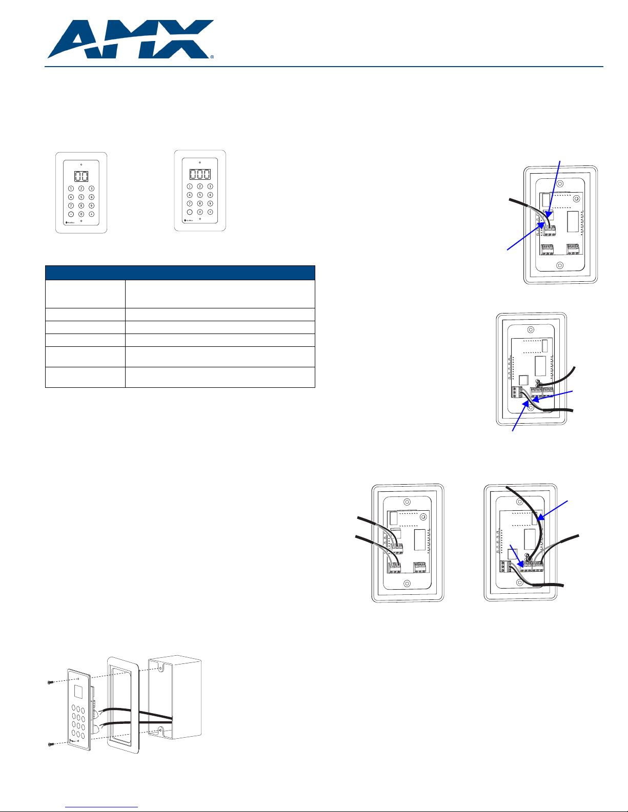
Wiring the Power Connector (P3)
2-digit Preset SBC
9a. Loosen the left and center screws of
the power connector P3 on the circuit
board on the back of the SBC
(see right).
9b. Insert power cables wires; positive
lead on the left and ground in center.
Tighten screws.
Power
cable
GND
P3
POS (+)
3-digit Preset SBC
9c. Attach a chassis ground wire with a
female quick disconnect to the
.250 x .032 tab. Connect the other end
of the ground wire to a ground point.
9d. Loosen the top and center screws of
the power connector P3 on the circuit
board on the back of the SBC
(see right).
9e. Insert power cable wires; positive lead
on top and ground in the center.
Tighten screws.
Wiring the Link Connector (P4 or P5)
Wire the SBC Link connector , either P4 o r P5. S tep s 10 and 11 apply to b oth the 2-digit
and 3-digit SBC.
Power cable
Link cable
P3
GND
Chassis
ground
wire
POS (+)
Power
cable
Chassis
ground
wire
Link cable
P4
P4
P5
FIG. 3 Attach XNNet link cable to P4 or P5
10. Loosen the two outer screws of the link conn ector (P4 o r P5) on th e SBC (FIG. 3
left for 2-digit SBC rear; FIG. 3 right for 3-digit SBC).
11. Insert XNNet link cable wires into link connector. Either wire goes into either
outside slot.
Tighten screws.
12. Insert screws through mounting holes on SBC faceplate and holes on singlegang box (FIG. 2) and tighten.
P5
Power cable
SB03
FIG. 2 Route wires through the single-gang box & attach to Preset SBC
Page 2
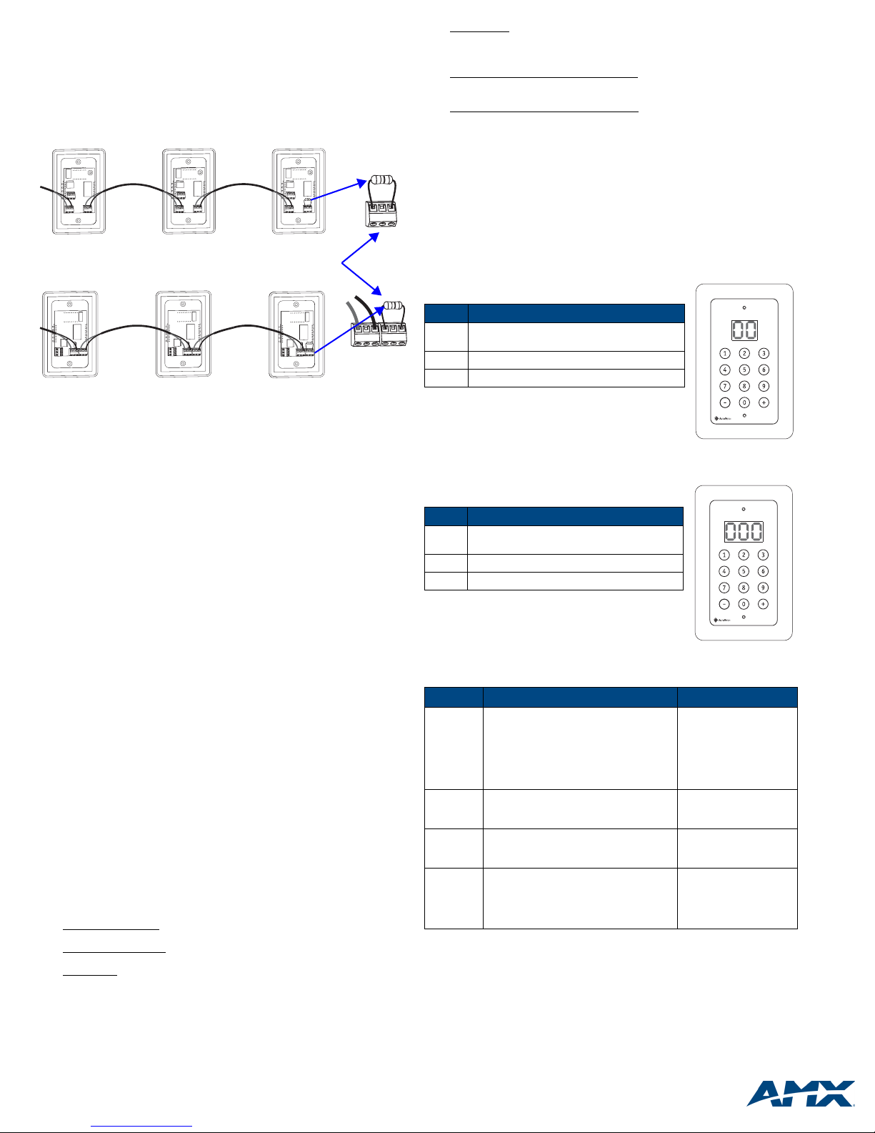
Linking Multiple Preset SBCs
Note: Each enclosure supports 32 Preset SBCs (or a total of 32 XNNet compatible
devices, such as remote control panels and status displays).
Preset SBCs can be linked together in a daisy chain to create multiple control points
for a single system. XNNet link cables can be attached to either Comm Link. The
total distance of the cable runs cannot exceed 1,000 ft. (304.8 m).
To link Preset SBCs:
2-digit SBCs linked
3-digit SBCs linked
Linking Preset SBCs in a daisy-chain
FIG. 4
1. Connect the first Preset SBC to the router using one of the Comm Links
(P4 or P5; see Steps 9 through 11 previous page).
2. Attach an XNNet link cable to the Preset SBC’ s other Comm Li nk, following the
same procedure used when connecting to the router.
3. Attach the other end of the XNNet cable t o a Comm Link on t he second P reset
SBC.
4. Repeat Steps 2 and 3 for any additional Preset SBCs.
5. If required* terminate the final SBC. Loosen the two outer screws, insert a 120
ohm resistor (customer supplied) in the outer contacts, and tighten the screws
(FIG 4).
*On large control networks, termination may be required on the last linked
Preset SBC.
Termination may be
required (see Step 5)
Operation
Apply power to the Preset SBC and the system (see router's documentation for
powering up procedure).
Programming & Entering Presets
Note: Preset SBCs cannot be programmed to act as a standard channel selector
device to a specific output.
To program presets:
Local presets must be pre-programmed in XNConnect and executed on a single
virtual matrix. For instructions on programming local presets see the XNConnect
Help file.
Global presets can either be defined using BCS commands or from a control p anel (if
supported by the panel) and affect routing on all virtual matrices. For instructions on
programming global presets, see the BCS commands documentation.
Entering Presets
Important: Accessing local presets may require changing the current virtual matrix
(VM); accessing global presets requires a virtual matrix setting of “99” or “999 ”.
To enter local or global presets:
Note: The following steps apply if the virtual matrix setting needs to be changed to
access programmed presets.
1. To determine the SBC's current VM, hold down the 0 key for five seconds until
the screen flares (e.g., characters briefly brighten, then repetitively dim to
normal; display never goes blank); then release key.
VM number displayed
executing local presets (on a single virtual matrix).
“99” or “999” displayed
global presets (which can include multiple virtual matrices).
2. Local preset
If the VM number displayed is not correct, enter the number of the VM (e.g.,
enter “01” or “001” for VM 1). Wait until the display stops flashing (approx. five
seconds), then enter the local preset number . If t he display is “99” or “999”, the
VM setting must be changed to execute a local preset (see Step 3).
– indicates the SBC is currently set on a VM for
– indicates the SBC is currently set for executing
– if the VM number displayed is correct, enter the preset number.
Global preset
(approx. five seconds), then enter the global preset number. If the display is a
VM number, the VM setting must be changed to execute a global preset (see
Step 3).
3. Change the VM setting from local to global
the display stops flashing (approx. five seconds), then enter the global preset
number.
Change the VM setting from global to local
(e.g., enter “01” or “001” for VM 1). Wait until the display stops flashing
– if the display is “99” or “999” wait until the display stop s flashing
by entering “99” or “999”. Wait until
by entering the number of the VM
(approx. five seconds), then enter the local preset number.
Executing Switches & LED Display
When the system is powered up, the LED on the SBC Preset flashes for two seconds
and then displays the current virtual matrix number or displays “99” or “999” if it is
ready for a global preset.
The scrolling ranges for global presets are 1 to 64. For local presets, the scrolling
ranges are 1 to 99 on a 2-digit display, and 1 to 999 on a 3-digit display. If you select
an invalid local preset number (e.g., a number for which a local preset had not been
defined), the Preset SBC will display error code E2.
To operate the 2-digit Preset SBC:
Press the keys according to their function as indicated.
Keys Function
Number Allows direct switching to a different preset
selection without scrolling
+ Increases preset selection by one
- Decreases preset selection by one
Enter a two digit number (e.g., for preset # 4, enter “04”).
Within two seconds of pressing the first digit, press the
second one.
Enter “00” to clear the display.
To operate the 3-digit Preset SBC:
Press the keys according to their function as indicated.
Keys Function
Number Allows direct switching to a different preset
selection without scrolling
+ Increases preset selection by one
- Decreases preset selection by one
Enter a three digit number (e.g., for preset # 15, en ter “015”)
Within two seconds of pressing the first digit, press the
second digit; within another two seconds, press the third
digit.
Enter “000” to clear the display.
Error Codes / Troubleshooting
Code
E1
Request
Timed Out
E2
Virtual
Matrix Error
E3
Display
Error
E4
Fragmented
Control Overrun – commands sent too
quickly.
Problem with physical connection to system
Configuration problem Ensure preset number is
The preset is valid, but cannot be displayed
because it is higher than 99 on a
2-digit display, or 999 on a 3-digit display
A breakaway switch was made causing
status mismatch between one or more
components in a grouping
Causes Actions
Re-enter commands
Check cable connections
Check preset number
setting for the Preset SBC
valid and on the correct
virtual matrix
Enter valid preset
number
Check status on different
levels using another
control method to find
status mismatch; reroute
switch
Cleaning
Preset SBCs require only topical cleaning. Use a dry cloth and mild glass cleaner to
clean the surface of the Preset SBC. Do not use abrasive cleaners to clean the
faceplate.
For full warranty information, refer to www.amx.com
©2007 AMX. All rights reserved. AMX and the AMX logo are registered trademarks of AMX.
3000 RESEARCH DRIVE, RICHARDSON, TX 75082 • 800.222.0193 • fax 469.624.7153 • technical support 800.932.6993 • www.amx.com
AMX reserves the right to alter specifications without notice at any time.
93-900-831 REV: B
7/07
 Loading...