

Page 1

instruction manual
RMS CodeCrafter
Software
Page 2

AMX Limited Warranty and Disclaimer
AMX Corporation warrants its products to be free of defects in material and workmanship under normal use for three
(3) years from the date of purchase from AMX Corporation, with the following exceptions:
• Electroluminescent and LCD Control Panels are warranted for three (3) years, except for the display and touch
overlay components that are warranted for a period of one (1) year.
• Disk drive mechanisms, pan/tilt heads, power supplies, and MX Series products are warranted for a period of one
(1) year.
• AMX Lighting products are guaranteed to switch on and off any load that is properly connected to our lighting
products, as long as the AMX Lighting products are under warranty. AMX Corporation does guarantee the
control of dimmable loads that are properly connected to our lighting products. The dimming performance or
quality cannot be guaranteed due to the random combinations of dimmers, lamps and ballasts or transformers.
• Unless otherwise specified, OEM and custom products are warranted for a period of one (1) year.
• AMX Software is warranted for a period of ninety (90) days.
• Batteries and incandescent lamps are not covered under the warranty.
This warranty extends only to products purchased directly from AMX Corporation or an Authorized AMX Dealer.
All products returned to AMX require a Return Material Authorization (RMA) number. The RMA number is
obtained from the AMX RMA Department. The RMA number must be clearly marked on the outside of each box.
The RMA is valid for a 30-day period. After the 30-day period the RMA will be cancelled. Any shipments received
not consistent with the RMA, or after the RMA is cancelled, will be refused. AMX is not responsible for products
returned without a valid RMA number.
AMX Corporation is not liable for any damages caused by its products or for the failure of its products to perform.
This includes any lost profits, lost savings, incidental damages, or consequential damages. AMX Corporation is not
liable for any claim made by a third party or by an AMX Dealer for a third party.
This limitation of liability applies whether damages are sought, or a claim is made, under this warranty or as a tort
claim (including negligence and strict product liability), a contract claim, or any other claim. This limitation of
liability cannot be waived or amended by any person. This limitation of liability will be effective even if AMX Corpo-
ration or an authorized representative of AMX Corporation has been advised of the possibility of any such damages.
This limitation of liability, however, will not apply to claims for personal injury.
Some states do not allow a limitation of how long an implied warranty last. Some states do not allow the limitation or
exclusion of incidental or consequential damages for consumer products. In such states, the limitation or exclusion of
the Limited Warranty may not apply. This Limited Warranty gives the owner specific legal rights. The owner may
also have other rights that vary from state to state. The owner is advised to consult applicable state laws for full
determination of rights.
EXCEPT AS EXPRESSLY SET FORTH IN THIS WARRANTY, AMX CORPORATION MAKES NO
OTHER WARRANTIES, EXPRESSED OR IMPLIED, INCLUDING ANY IMPLIED WARRANTIES OF
MERCHANTABILITY OR FITNESS FOR A PARTICULAR PURPOSE. AMX CORPORATION
EXPRESSLY DISCLAIMS ALL WARRANTIES NOT STATED IN THIS LIMITED WARRANTY. ANY
IMPLIED WARRANTIES THAT MAY BE IMPOSED BY LAW ARE LIMITED TO THE TERMS OF THIS
LIMITED WARRANTY.
Page 3

Software License and Warranty Agreement
LICENSE GRANT.
AMX grants to Licensee the non-exclusive right to use the AMX Software in the manner described in this License. The AMX Software
is licensed, not sold. The AMX Software consists of generally available programming and development software, product
documentation, sample applications, tools and utilities, and miscellaneous technical information. Please refer to the README.TXT
file on the compact disc or download for further information regarding the components of the AMX Software. The AMX Software is
subject to restrictions on distribution described in this License Agreement. YOU MAY NOT LICENSE, RENT, OR LEASE THE AMX
SOFTWARE. You may not reverse engineer, decompile, or disassemble the AMX Software.
INTELLECTUAL PROPERTY.
The AMX Software is owned by AMX and is protected by United States copyright laws, patent laws, international treaty provisions,
and/or state of Texas trade secret laws. Licensee may make copies of the AMX Software solely for backup or archival purposes.
Licensee may not copy the written materials accompanying the AMX Software.
TERMINATION. AMX RESERVES THE RIGHT, IN ITS SOLE DISCRETION, TO TERMINATE THIS LICENSE FOR
ANY REASON AND UPON WRITTEN NOTICE TO LICENSEE.
In the event that AMX terminates this License, the Licensee shall return or destroy all originals and copies of the AMX Software to
AMX and certify in writing that all originals and copies have been returned or destroyed.
PRE-RELEASE CODE.
Portions of the AMX Software may, from time to time, as identified in the AMX Software, include PRE-RELEASE CODE and such
code may not be at the level of performance, compatibility and functionality of the final code. The PRE-RELEASE CODE may not
operate correctly and may be substantially modified prior to final release or certain features may not be generally released. AMX is
not obligated to make or support any PRE-RELEASE CODE. ALL PRE-RELEASE CODE IS PROVIDED "AS IS" WITH NO
WARRANTIES.
LIMITED WARRANTY.
AMX warrants that the AMX Software will perform substantially in accordance with the accompanying written materials for a period of
ninety (90) days from the date of receipt. AMX DISCLAIMS ALL OTHER WARRANTIES, EITHER EXPRESS OR IMPLIED,
INCLUDING, BUT NOT LIMITED TO IMPLIED WARRANTIES OF MERCHANTABILITY AND FITNESS FOR A PARTICULAR
PURPOSE, WITH REGARD TO THE AMX SOFTWARE. THIS LIMITED WARRANTY GIVES YOU SPECIFIC LEGAL RIGHTS.
Any supplements or updates to the AMX SOFTWARE, including without limitation, any (if any) service packs or hot fixes provided to
you after the expiration of the ninety (90) day Limited Warranty period are not covered by any warranty or condition, express, implied
or statutory.
LICENSEE REMEDIES.
AMX's entire liability and your exclusive remedy shall be repair or replacement of the AMX Software that does not meet AMX's
Limited Warranty and which is returned to AMX. This Limited Warranty is void if failure of the AMX Software has resulted from
accident, abuse, or misapplication. Any replacement AMX Software will be warranted for the remainder of the original warranty period
or thirty (30) days, whichever is longer. Outside the United States, these remedies may not available.
NO LIABILITY FOR CONSEQUENTIAL DAMAGES. IN NO EVENT SHALL AMX BE LIABLE FOR ANY DAMAGES
WHATSOEVER (INCLUDING, WITHOUT LIMITATION, DAMAGES FOR LOSS OF BUSINESS PROFITS, BUSINESS
INTERRUPTION, LOSS OF BUSINESS INFORMATION, OR ANY OTHER PECUNIARY LOSS) ARISING OUT OF THE USE OF OR
INABILITY TO USE THIS AMX SOFTWARE, EVEN IF AMX HAS BEEN ADVISED OF THE POSSIBILITY OF SUCH DAMAGES.
BECAUSE SOME STATES/COUNTRIES DO NOT ALLOW THE EXCLUSION OR LIMITATION OF LIABILITY FOR
CONSEQUENTIAL OR INCIDENTAL DAMAGES, THE ABOVE LIMITATION MAY NOT APPLY TO YOU.
U.S. GOVERNMENT RESTRICTED RIGHTS. The AMX Software is provided with RESTRICTED RIGHTS. Use, duplication, or
disclosure by the Government is subject to restrictions as set forth in subparagraph (c)(1)(ii) of The Rights in Technical Data and
Computer Software clause at DFARS 252.227-7013 or subparagraphs (c)(1) and (2) of the Commercial Computer Software
Restricted Rights at 48 CFR 52.227-19, as applicable.
This Agreement replaces and supercedes all previous AMX Software License Agreements and is governed by the laws
of the State of Texas, and all disputes will be resolved in the courts in Collin County, Texas, USA. Should you have any
questions concerning this Agreement, or if you desire to contact AMX for any reason, please write: AMX Corporation,
3000 Research Drive, Richardson, TX 75082.
Page 4

Page 5

Table of Contents
Table of Contents
Welcome to RMS CodeCrafter .................................................................................1
System Requirements ....................................................................................................... 1
Other PC requirements: ........................................................................................................... 1
The RMS CodeCrafter Work Area ...........................................................................3
Menu Bar........................................................................................................................... 3
File Menu ................................................................................................................................. 3
Edit Menu ................................................................................................................................. 3
View Menu ............................................................................................................................... 4
Help Menu................................................................................................................................ 4
Toolbar .............................................................................................................................. 4
Text Field Context Menu ................................................................................................... 5
RMS CodeCrafter Device Template Pages .............................................................7
Device Templates.............................................................................................................. 7
Device Template Main Page ............................................................................................. 7
Device Template Parameters Page .................................................................................. 9
Add/Edit Device Template Parameters Window .................................................................... 10
Set Range for Index or Enum Parameter............................................................................... 12
Device Template Final Page ........................................................................................... 13
RMS CodeCrafter MeetingManager Project Pages ..............................................15
Introductory Page ............................................................................................................ 15
Preferences Window .............................................................................................................. 16
Code Generation Wizard - Start Page............................................................................. 17
Code File Selection Page................................................................................................ 18
Room Information/Options Page ..................................................................................... 18
RMS Server Address Page ............................................................................................. 20
RMS Virtual and Socket Device Definitions Page........................................................... 21
Scheduling: Main Panels Page ....................................................................................... 22
Add/Edit Main Panel Window ................................................................................................. 23
Scheduling: Welcome Panels Page ................................................................................ 24
Add/Edit Welcome Panel Window.......................................................................................... 25
Named NetLinx Devices Page ........................................................................................ 26
Add/Edit Named Devices Window ......................................................................................... 27
Add All Welcome and Main Panels Window .......................................................................... 27
Monitored Third-Party Devices Page .............................................................................. 28
Add/Edit Monitored Devices Window ..................................................................................... 29
RMS CodeCrafter
i
Page 6

Table of Contents
Add Device from Template Window ....................................................................................... 30
Device Parameters Page ................................................................................................ 31
Add/Edit Device Parameters Window .................................................................................... 32
Set Range for Index or Enum Parameter............................................................................... 34
i!-ConnectLinx Touch Panel Button Mappings Page....................................................... 35
Edit Touch Panel Button-mappings........................................................................................ 36
Generate NetLinx Code File Page .................................................................................. 37
Code Generation Wizard - Finished Page ...................................................................... 38
RMS CodeCrafter AssetManager Project Pages .................................................39
Introductory Page............................................................................................................ 39
Preferences Window .............................................................................................................. 40
Code Generation Wizard - Start Page ............................................................................ 41
Code File Selection Page................................................................................................ 42
Room Information/Options Page..................................................................................... 42
RMS Server Address Page ............................................................................................. 44
RMS Virtual and Socket Device Definitions Page........................................................... 45
Help Desk: Display Panels Page .................................................................................... 46
Add/Edit Help Desk Panel Window ........................................................................................ 47
Named NetLinx Devices Page ........................................................................................ 48
Add/Edit Named Devices Window ......................................................................................... 49
Add All Welcome and Main Panels Window .......................................................................... 50
Monitored Third-Party Devices Page .............................................................................. 50
Add/Edit Monitored Devices Window ..................................................................................... 51
Add Device from Template Window ....................................................................................... 53
Device Parameters Page ................................................................................................ 54
Add/Edit Device Parameters Window .................................................................................... 55
Set Range for Index or Enum Parameter............................................................................... 57
i!-ConnectLinx Touch Panel Button Mappings Page....................................................... 58
Edit Touch Panel Button-mappings........................................................................................ 59
Generate NetLinx Code File Page .................................................................................. 60
Code Generation Wizard - Finished Page ...................................................................... 61
Basic Operations ....................................................................................................63
Creating A New Device Template ................................................................................... 63
Creating A New AssetManager Project........................................................................... 64
Creating A New MeetingManager Project....................................................................... 66
Saving A Device Template File ....................................................................................... 68
Saving A Project File....................................................................................................... 68
Opening An Existing Device Template............................................................................ 68
ii
RMS CodeCrafter
Page 7

Table of Contents
Opening An Existing Project............................................................................................ 69
Closing A Project Or Template File ................................................................................. 69
Importing RMS SDK Spreadsheets................................................................................. 69
SERVERINFO.TXT Window ........................................................................................... 70
Exiting RMS CodeCrafter ................................................................................................ 71
Adjusting RMS CodeCrafter ............................................................................................ 71
Changing Visual Style ............................................................................................................ 71
Web Update ........................................................................................................................... 71
Setting Template Folder Destination ...................................................................................... 71
Setting Default R.M.S. Server Address.................................................................................. 72
Setting Wizard to Generate Device Variable Warnings ......................................................... 72
Code Generation .....................................................................................................73
File Header...................................................................................................................... 73
DEFINE_DEVICES Section ............................................................................................ 73
Device definitions ................................................................................................................... 73
Device Definition Warnings .................................................................................................... 73
DEFINE_CONSTANT Section ........................................................................................ 74
Server Address Definition ...................................................................................................... 74
Maximum String/Enum Param Length ................................................................................... 74
RMSCommon.axi ............................................................................................................ 74
DEFINE_VARIABLE Section........................................................................................... 74
Device Arrays......................................................................................................................... 74
i!-ConnectLinx variables ......................................................................................................... 75
Function Definitions......................................................................................................... 77
RMSCommon Callbacks ........................................................................................................ 77
RMSDevMonRegisterCallBack .............................................................................................. 77
RMSDevMonSetParamCallBack............................................................................................ 77
RMS Device Parameters........................................................................................................ 78
Module Definitions........................................................................................................... 78
Monitored Device/Support Modules ....................................................................................... 78
Source Usage ........................................................................................................................ 78
RMS Engine ........................................................................................................................... 78
RMSUIMod............................................................................................................................. 78
RMSWelcomeOnlyUIMod ...................................................................................................... 79
KeyboardMod......................................................................................................................... 79
i!-ConnectLinxEngineMod ...................................................................................................... 79
RMSHelpUIMod (AssetManager only) ................................................................................... 79
Event Definitions ............................................................................................................. 80
RMS Engine Device ............................................................................................................... 80
RMS CodeCrafter
iii
Page 8

Table of Contents
Named Devices...................................................................................................................... 80
Monitored Devices ................................................................................................................. 81
Device Parameters................................................................................................................. 81
i!-ConnectLinx ........................................................................................................................ 81
LEVEL_EVENT Block ............................................................................................................ 81
DATA_EVENT Block.............................................................................................................. 82
BUTTON_EVENT Block......................................................................................................... 83
CHANNEL_EVENT Block ...................................................................................................... 84
RMS Concepts ........................................................................................................85
Device Monitoring Framework ........................................................................................ 85
Device Values ........................................................................................................................ 85
Parameter Values .................................................................................................................. 86
Status Types .......................................................................................................................... 87
RMS SDK And RMS CodeCrafter................................................................................... 88
i!-ConnectLinx ........................................................................................................89
Using i!-ConnectLinx ....................................................................................................... 89
iv
RMS CodeCrafter
Page 9

Welcome to RMS CodeCrafter
RMS CodeCrafter allows you to create NetLinx include files that contain the code necessary for
monitoring devices using one of the products in the Resource Management Suite, i.e.,
MeetingManager.
RMS CodeCrafter is a wizard application where the output is determined by data and device
information provided by you. As you navigate through the wizard, the options you select and the
data you provide will determine the NetLinx code generated in the final page.
System Requirements
RMS CodeCrafter will support the following platforms:
Windows 2000 (Service Pack 3 or greater)
If you are installing on a Windows 2000 machine, you must have Administrator rights
to install and run all required System files.
Windows XP Professional (Service Pack 1 or greater)
Welcome to RMS CodeCrafter
Other PC requirements:
Windows-compatible CD-ROM drive.
Windows-compatible mouse (or other pointing device).
At least 250 MB of free disk space.
RMS CodeCrafter will not work properly if your display settings is set to Large Font.
RMS CodeCrafter
1
Page 10

Welcome to RMS CodeCrafter
2
RMS CodeCrafter
Page 11

The RMS CodeCrafter Work Area
Menu Bar
File Menu
The File menu serves as a location for file management, project information and template
management.
New - Choose between:
New Project - Opens a new RMS CodeCrafter project file (.CGP) and progresses to the
Project Start Page.
New Template - Opens a new RMS CodeCrafter template file (.CGT) and progresses to
the Device Template Main Page.
Open - Choose between:
Open Project - After selecting the desired file in the open dialog window, it opens an
existing RMS CodeCrafter project file (.CGP) and progresses to the Project Start Page.
The RMS CodeCrafter Work Area
Open Template - After selecting the desired file in the open dialog window, it opens an
existing RMS CodeCrafter template file (.CGT) and progresses to the Device Template
Main Page.
Close - Closes the project or template file currently open. If the file has been edited, or is "dirty" as
indicated at the top of the window with an asterisks next to the file name, you are prompted to save
changes before closing.
Save - Saves changes made to either project or template file currently open. If the file has not been
previously been saved you are prompted to name and designate where to save the file.
Transfer Server Address File - Opens the SERVERINFO.TXT window.
Save As - Opens the save file dialog, allowing you to specify the file name and location which to
save.
Most Recently Used List - A list of most recently opened file names.
Exit - Closes the RMS CodeCrafter Wizard.
Edit Menu
The Edit Menu applies to text changes made within the RMS CodeCrafter wizard.
Undo - Undoes action taken in text areas.
Cut - Cut highlighted text from fields.
Copy - Copy highlighted text within fields.
RMS CodeCrafter
Paste - Paste cut and copied text into selected fields.
Delete - Delete selected text within fields.
Preferences - Launches the Preferences window.
3
Page 12
The RMS CodeCrafter Work Area
View Menu
The View menu allows you to toggle the toolbar and status bar of the RMS CodeCrafter wizard on
and off. A check next to the title indicates it is visible. Additionally you can change the appearance
of the application itself.
Visual Style - A list of visual appearances for the wizard. Select one of the following:
Default
Office XP®
Office 2003®
Help Menu
The Help menu contains features for updating the application and provides a resource
for understanding the RMS CodeCrafter wizard.
Contents - Launches the RMS CodeCrafter help, Contents section.
Web Update - Launches the AMX Web Update utility. Internet connection is necessary.
About RMS CodeCrafter - Displays the about RMS CodeCrafter dialog containing information
pertaining to version and copyright.
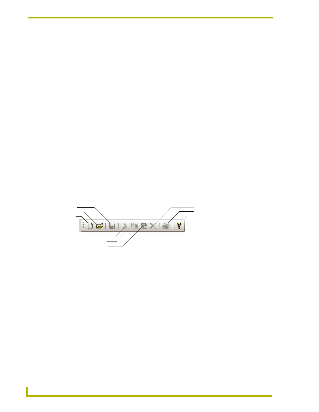
Toolbar
The toolbar contains icons for the commonly used functions:
Save
Open
New
Cut
Copy
Paste
FIG. 1 RMS CodeCrafter Wizard Toolbar
New - Launches the Project Start page.
Open - Launches the open project dialog window.
Save - Saves changes made to either project or template file currently open. If the file has not been
previously been saved you are prompted to name and designate where to save the file.
Cut - Cut highlighted text from fields.
Copy - Copy highlighted text within fields.
Paste - Paste cut and copied text into selected fields.
Delete - Delete selected text within fields.
Delete
Print
Help
Print - Prints the active generated code.
Help - Launches the RMS CodeCrafter help file.
4
RMS CodeCrafter
Page 13

Text Field Context Menu
Right click within any text field to access the text field context menu.
Undo - Undoes last text action.
Cut - Cuts selected text to the clipboard.
Copy - Copies selected text to the clipboard.
Paste - Pastes text from clipboard into text field.
Delete - Deletes selected text.
Select All - Selects all text within the field.
The RMS CodeCrafter Work Area
RMS CodeCrafter
5
Page 14

The RMS CodeCrafter Work Area
6
RMS CodeCrafter
Page 15
RMS CodeCrafter Device Template Pages
RMS CodeCrafter Device Template Pages
Device Templates
You can create persistent templates for monitored devices, where you provide the settings and
parameters. RMS CodeCrafter can then use the device templates for similar or the same devices in
other projects.
When you opt to use device templates RMS CodeCrafter pulls all available templates from the
template folder destination, which you can set in the Preferences window. You can create a new
template or open an existing template from within the File menu but either way you are brought to
the Device Template Main page to edit and set parameters.
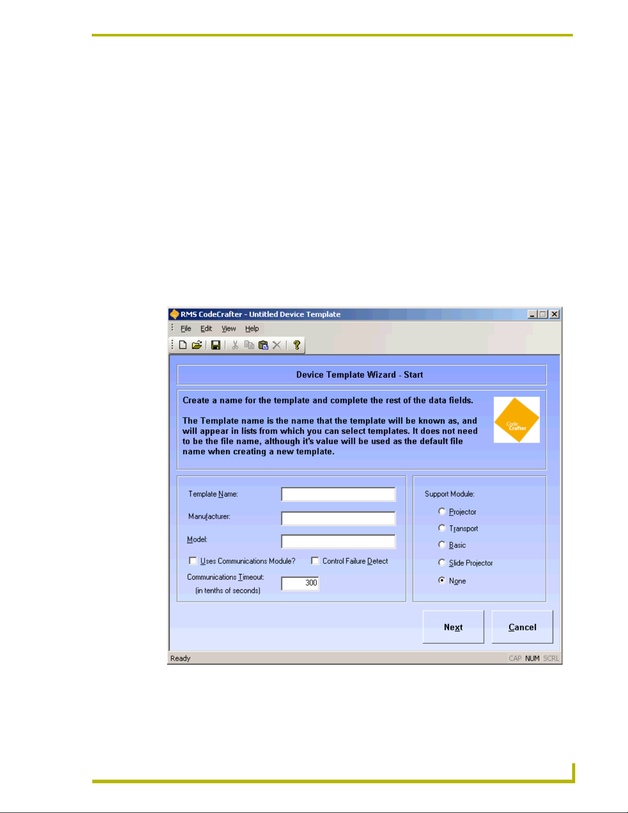
Device Template Main Page
The Device Template Main page is the first page of the template creation process.
MS CodeCrafter
FIG. 2 Device Template Main Page
7
Page 16

RMS CodeCrafter Device Template Pages
Template Name - This is the template name provided by you. This is not the file name but by
default it will be used as such when saving. Template name is displayed as a selection when you are
associating new monitored devices with an existing template.
Manufacturer - This is a text field where you can provide the manufacturer information for the
device.
Model - This is a text field where you can provide the model information for the device.\
Uses Communications Module? - Place a check in the box to enable the function. The template
will use a communication module.
Communication Timeout - Measured in 1/10ths of a second, where 0 is a valid value. If no
timeout is required, use -1.
Control Failure Detect - Placing a check in the box adds a call to RMSEnablePowerFailure() in
the generated code file.
Support Module - Click the radio button that best represents the device for the template.
Projector
Transport
Basic
Slide Projector
None
Next - Progresses the wizard to the Device Template Parameters page.
8
RMS CodeCrafter
Page 17
RMS CodeCrafter Device Template Pages
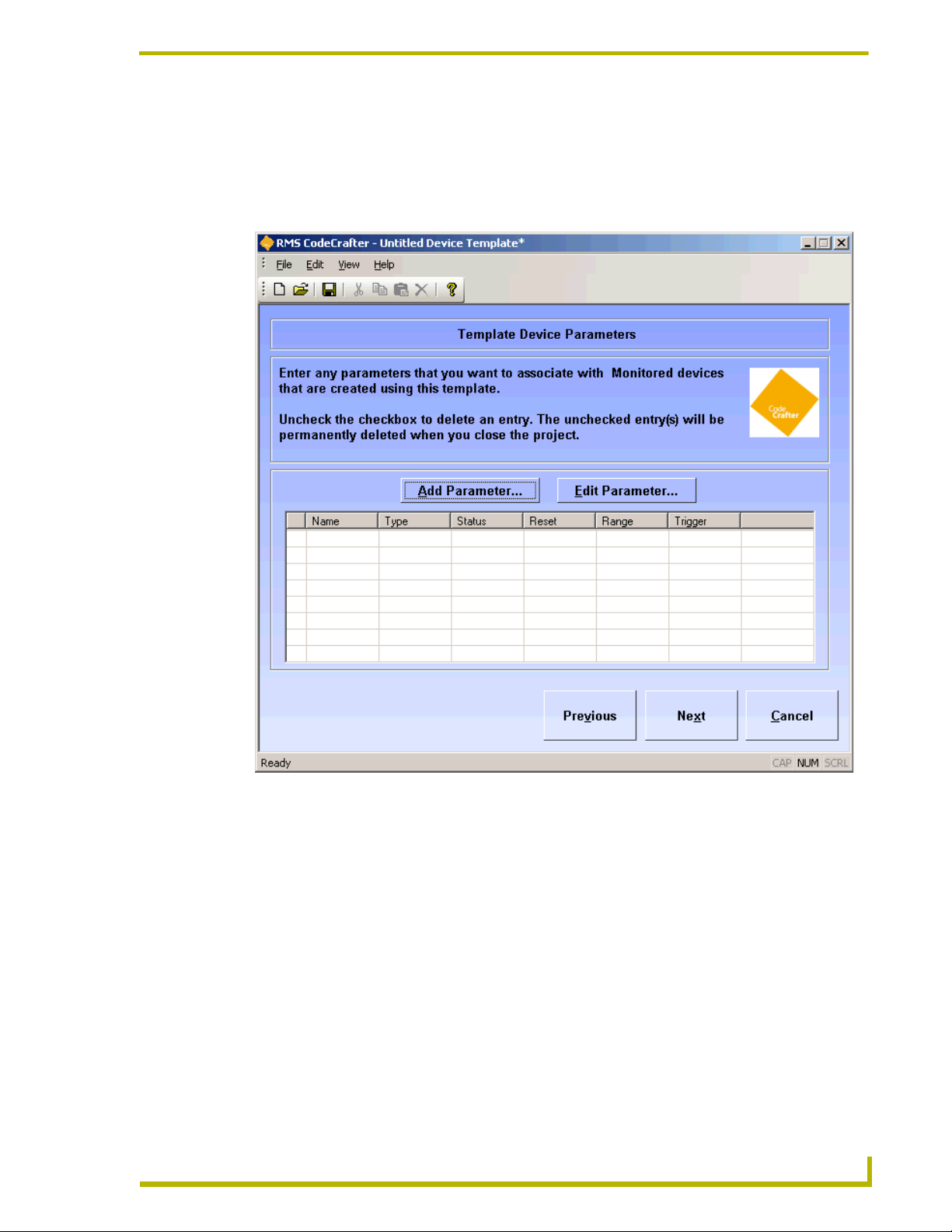
Device Template Parameters Page
The Device Parameters page is a list of available parameters that can be included with the template.
There is a grid displaying all device parameters currently within the template. In the left-hand
column is a checkbox, when selected indicates the entry is to be deleted.
MS CodeCrafter
FIG. 3 Device Template Parameters Page
Add Parameter - Add a parameters entry.
Edit Parameter - Edit a selected parameters entry.
Next - Progresses the RMS CodeCrafter wizard to the Device Template Final page.
Previous - Regresses the RMS CodeCrafter wizard to the Device Template Main page.
9
Page 18
RMS CodeCrafter Device Template Pages
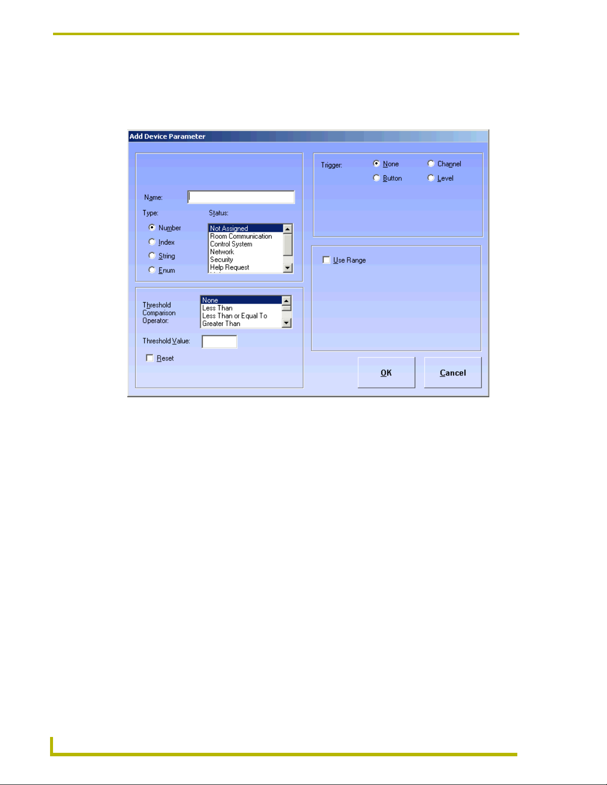
Add/Edit Device Template Parameters Window
The Add/Edit Device Template Parameters window allows you to add device parameters or edit
existing ones.
FIG. 4 Add/Edit Device Template Parameters Window
Name - A text field you can edit to name the parameter.
Type - Select one of the parameter types:
Number
Index
String
Enum
Status - select one from the scroll list:
Not Assigned
Room Communication
Control System
Network
Security
Help Request
Maintenance
10
RMS CodeCrafter
Page 19

RMS CodeCrafter Device Template Pages
Equipment Usage
Threshold Comparison Operator - select from the following:
None
Less Than
Less Than or Equal To
Greater Than
Greater Than or Equal To
Equal To
Not Equal To
Contains (String or Enum only)
Does Not Contain (String or Enum only)
Threshold Value - A text field you can edit to set threshold value. 32-bit signed number for
Number, 16-bit unsigned number for Index and any string up to 100 characters for String and
Enum.
Reset - Place a mark in the box to enable reset of threshold.
Reset Value - A text field you can edit to set reset value. 32-bit signed number for Number, 16-bit
unsigned number for Index and any string up to 100 characters for String and Enum.
Trigger - select one of the following:
None
Button
Channel
Level
Use Range (Number) - Sets the minimum and maximum for number; this value is optional.
Set Range (Enum or Index) - A drop down list of enumeration strings. You can elect to:
Add - adds the sting to the parameter use.
Remove - removes the string from parameter use.
Move Up - moves the string up the list of parameter use.
Move Down - moves the string down the list of parameter use.
OK - Closes the window and saves changes made.
Cancel - Closes window without implementing changes.
MS CodeCrafter
11
Page 20
RMS CodeCrafter Device Template Pages
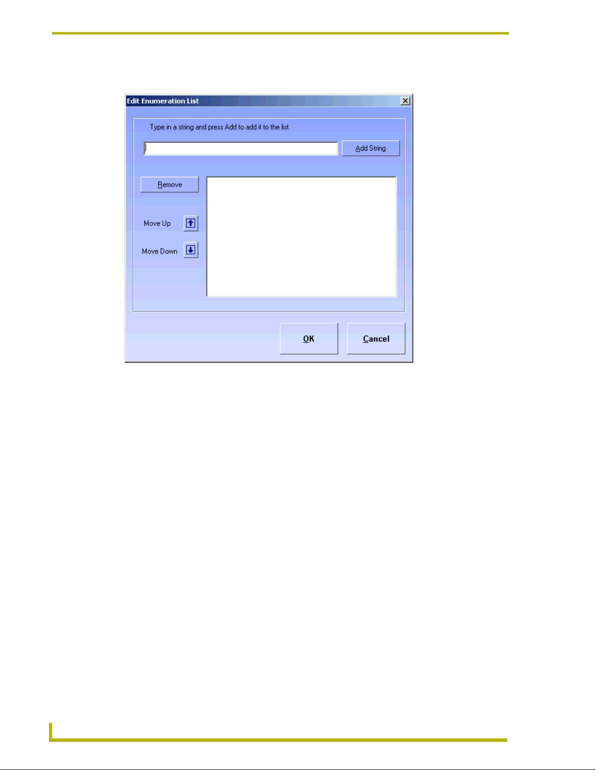
Set Range for Index or Enum Parameter
FIG. 5 Set Range for Index or Enum Parameter
Add string - adds the sting to the parameter use.
Remove - removes the string from parameter use.
Move Up - moves the string up the list of parameter use.
Move Down - moves the string down the list of parameter use.
OK - Closes the window and saves changes made.
Cancel - Closes window without implementing changes.
12
RMS CodeCrafter
Page 21
RMS CodeCrafter Device Template Pages
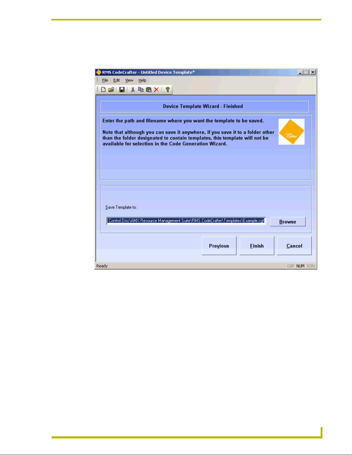
Device Template Wizard Finished Page
The Device Template Wizard Finished page is the last step in making a device template.
MS CodeCrafter
FIG. 6 Device Template Final Page
Save Template to - A text field where you can either type or click the Browse button to designate
where RMS CodeCrafter wizard is to save the template file (.CGT).
Previous - Regresses the RMS CodeCrafter wizard to the Device Template Parameters Page.
Finish - Generates the template file and stores in the directory specified by the Save Template to
field.
13
Page 22

RMS CodeCrafter Device Template Pages
14
RMS CodeCrafter
Page 23
RMS CodeCrafter MeetingManager Project Pages
RMS CodeCrafter MeetingManager Project
Pages
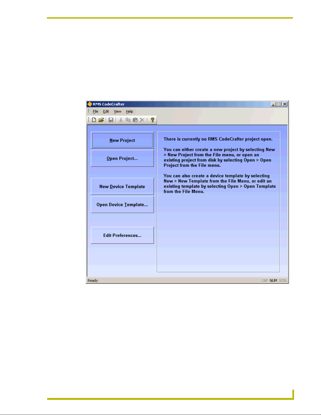
Introductory Page
The Introductory page is the initial page displayed upon launching the RMS CodeCrafter wizard.
RMS CodeCrafter
FIG. 7 Introductory Page
The button you select will determine what file is generated. The buttons are as follows:
New Project - Opens a new RMS CodeCrafter project file (.CGP) and progresses to the Project
Start Page.
Open Project - After selecting the desired file in the open dialog window, it opens an existing RMS
CodeCrafter project file (.CGP) and progresses to the Project Start Page.
New Device Template - Opens a new RMS CodeCrafter template file (.CGT) and progresses to the
Device Template Main Page.
Open Device Template - After selecting the desired file in the open dialog window, it opens an
existing RMS CodeCrafter template file (.CGT) and progresses to the Device Template Main Page.
15
Page 24
RMS CodeCrafter MeetingManager Project Pages
Additionally, you can set default features of the wizard with:
Edit Preferences - Launches the Preferences window.
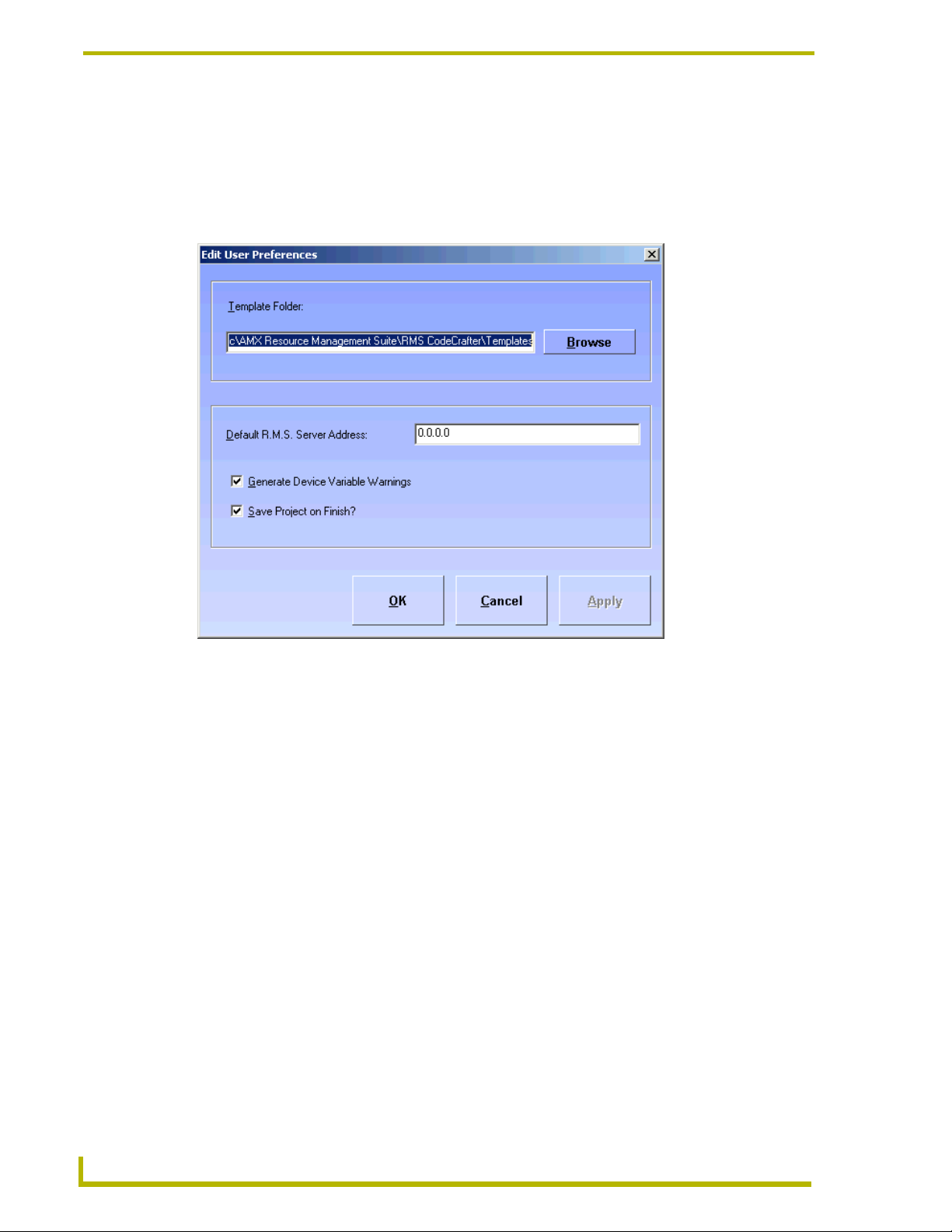
Preferences Window
RMS CodeCrafter allows you to set user preferences.
FIG. 8 Preferences Window
Template Folder - A text field where you can either type or click Browse to designate the default
template folder destination.
Default R.M.S. Server Address - A text field where you can edit the server address for the R.M.S.
server. The default value is 0.0.0.0.
Generate Device Variable Warnings - A checkbox, when enabled adds variable warnings in the
generated code.
Save Project on Finish? - A checkbox, when enabled automatically saves your project when you
click the final Finish button.
OK - Accepts the changes and closes the preferences window.
Cancel - Closes the preferences window without incorporating the changes.
16
RMS CodeCrafter
Page 25
RMS CodeCrafter MeetingManager Project Pages
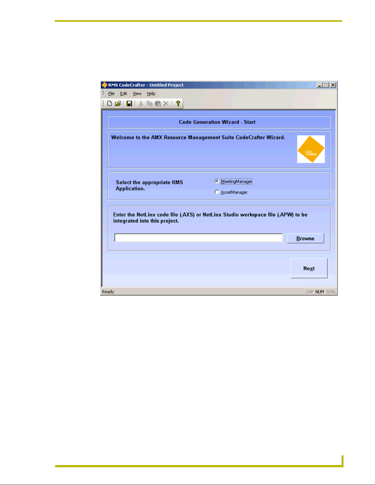
Code Generation Wizard - Start Page
The Code Generation Wizard - Start page is the first page you see when you open a new or existing
project file.
RMS CodeCrafter
FIG. 9 Project Start Page
Select the appropriate RMS application - This is the RMS application code you want generated.
Click the radio button to select. Your choices are:
MeetingManager (default)
AssetManager
Enter the NetLinx code file (.AXS) or NetLinx Studio workspace file (.APW) to be integrated
into this project. - Either type or click the Browse button for the location of the file to be integrated
into the project. The file can be either a NetLinx code (.AXS) or NetLinx Studio workspace
(.APW) file. The incorporation of either file into a RMS CodeCrafter project is optional.
Next - Progresses RMS CodeCrafter to the next page.
17
Page 26
RMS CodeCrafter MeetingManager Project Pages
Code File Selection Page
You will see the Code File Selection page if you selected a NetLinx Studio workspace file (.APW)
in the Project Start page. A list of all available NetLinx code files within the .APW file is displayed.
Previous - Returns the wizard back to the Project Start page.
Next - Progresses the RMS CodeCrafter wizard to the Room Information/Options page.
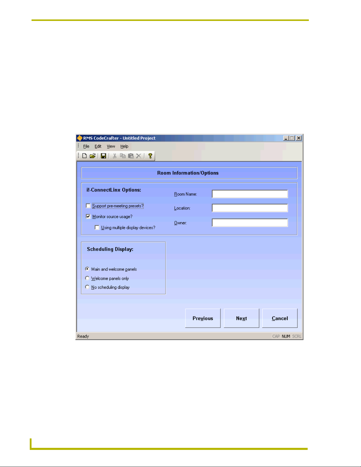
Room Information/Options Page
RMS CodeCrafter supports the ability to add scheduling and i!-ConnectLinx options to a project
file.
18
FIG. 10 Room Information/Options Page
i!-ConnectLinx Options:
Support pre-meeting presets? - Placing a check in this box determines if the i!-
ConnectLinx module is defined in the generated code file.
Monitor source usage? - Placing a check in this box determines if the
RMSSourceUsageMod is defined in the generated code file.
RMS CodeCrafter
Page 27

RMS CodeCrafter MeetingManager Project Pages
Using multiple display devices? - This option is only available when Monitor source
usage? has been selected. Placing a check in this box determines if a call to
RMSSetMultiSource(TRUE) is included in the DEFINE_EVENT section of the
generated code.
Room Name - A text field, you provide the name of the room. (This field is required)
Location - A text field, you provide the name of the location for the room. (This field is
required)
Owner - A text field, you provide the name of the person that owns the room. (This field
is required)
Scheduling Display:
Click on the radio button for one of these options:
Main and welcome panels - If selected, both the RMSUIMod and KeyboardMod modules
are defined in the generated code file. Additionally, the arrays these two modules are
dependant upon as input arguments are defined.
Welcome panels only - If selected, only the RMSWelcomeOnlyUIMod is defined in the
generated code. Additionally, the array of Welcome Panels is defined.
No scheduling display - If selected, no scheduling mods are included in the generated
code.
Previous - Regresses the RMS CodeCrafter wizard to the Code File Selection page.
Next - Progresses the RMS CodeCrafter wizard to the RMS Server Address page.
RMS CodeCrafter
19
Page 28
RMS CodeCrafter MeetingManager Project Pages
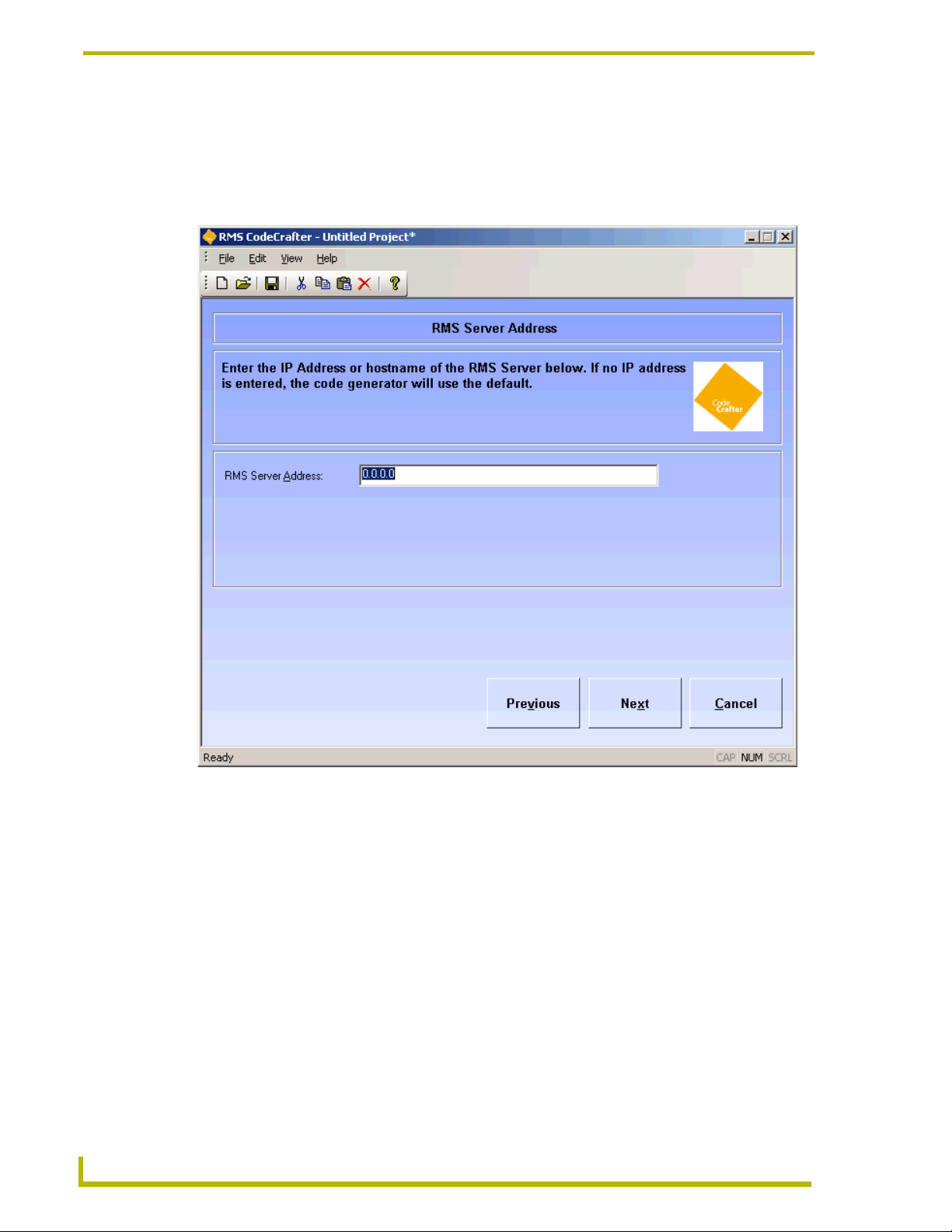
RMS Server Address Page
The RMS Server Address page allows you the opportunity to specify the IP address of the R.M.S.
server. This is optional and if left unchanged, the default specified in the Preferences window is
used.
20
FIG. 11 Server Address Page
R.M.S. Server Address - A text field where you can type the IP address of the R.M.S. server if
necessary.
Previous - Regresses the RMS CodeCrafter wizard to the Room Information/Options page.
Next - Progresses the RMS CodeCrafter wizard to the RMS Virtual and Socket Device Definitions
page.
RMS CodeCrafter
Page 29
RMS CodeCrafter MeetingManager Project Pages
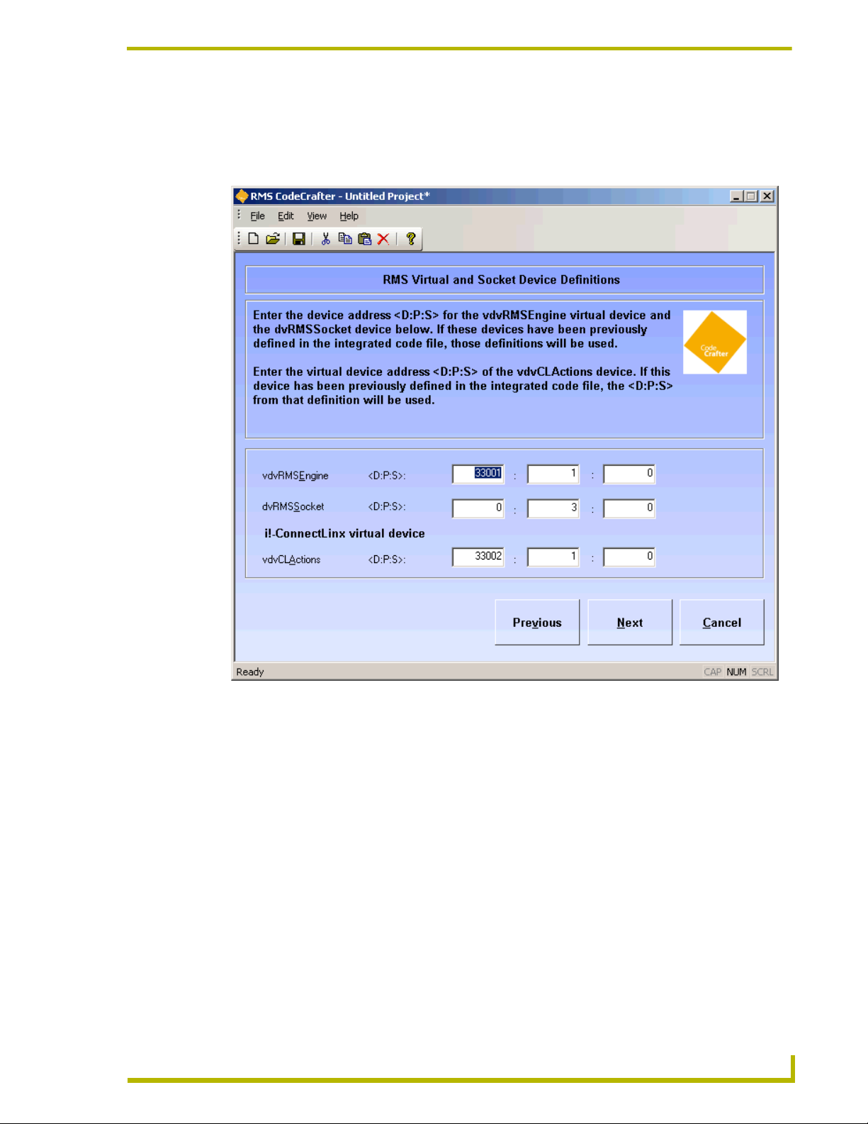
RMS Virtual and Socket Device Definitions Page
RMS Virtual and Socket Device Definitions page allows you to determine options related to i!-
ConnectLinx and Scheduling on the Scheduling And i!-ConnectLinx Options page.
RMS CodeCrafter
FIG. 12 RMS Devices Page
vdvRMSEngine - A text field you can edit and specify to meet your needs. The device, port and
socket location of the virtual device, RMS Engine.
dvRMSSocket - A text field you can edit and specify to meet your needs. The device, port and
socket location of the device, RMS Socket.
If these devices are defined in the integrated file, the fields are automatically populated and
protected.
i!-ConnectLinx virtual device:
vdvCLActions - A text field you can edit and specify to meet your needs. The device, port
and socket location of the virtual device, ConnectLinx.
If this device is defined in the integrated file, the fields are automatically populated and protected.
In the event the devices are not defined by the integrated file or there is no integrated file
for the project, the fields are populated by the following defaults:
21
Page 30
RMS CodeCrafter MeetingManager Project Pages
vdvRMSEngine - 33001:1:0
dvRMSSocket - 0:3:0
vdvCLActions - 33002:1:0
Device definitions are added to the generated code file; otherwise, a warning statement is added in
the generated code file.
Previous - Regresses the RMS CodeCrafter wizard to the Server Address page.
Next - Progresses the RMS CodeCrafter wizard to the Main Panels page.
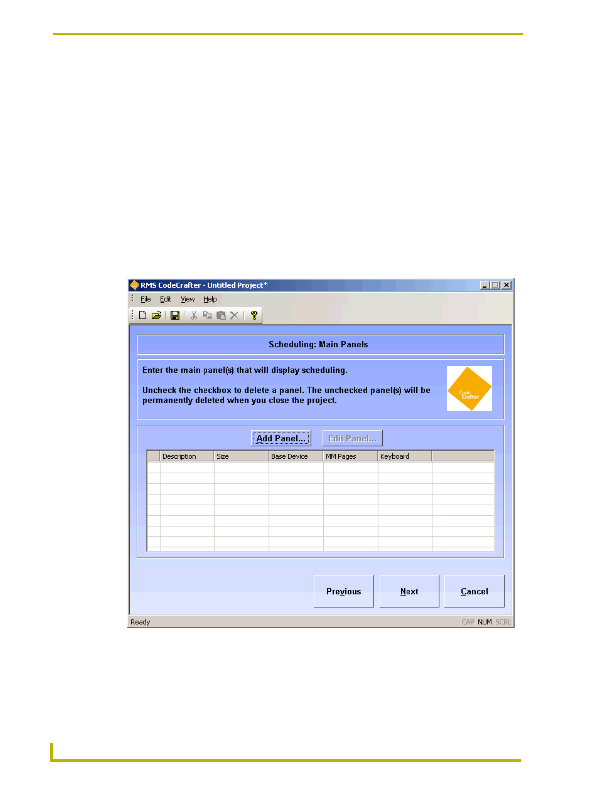
Scheduling: Main Panels Page
The Main Panels page allows you to add, edit and delete main panels used to display scheduling.
Main Panels page is only available if you selected Main and welcome panels on the Room
Information/Options page.
22
FIG. 13 Main Panels Page
Add Panel - Launches the Add/Edit Main Panel window. Adds a main panel to the project.
Edit Panel - Launches the Add/Edit Main Panel window. When a main panel is selected you can
edit its properties.
RMS CodeCrafter
Page 31

RMS CodeCrafter MeetingManager Project Pages
The main panel grid lists all panels available for the project. Any entry not selected with a check
will be removed from the project upon closing the project.
Previous - Regresses the RMS CodeCrafter wizard to the RMS Virtual and Socket Device
Definitions page.
Next - Progresses the RMS CodeCrafter wizard to the Scheduling: Welcome Panels page.
Add/Edit Main Panel Window
FIG. 14 Add/Edit Main Panel Window
The Add/Edit Main Panel window is available to add and edit panel information. The fields you can
edit are as follows:
Panel Size - A list of supported panel sizes supported by RMS CodeCrafter, click on your desired
panel size to select.
Description - A text field you can edit to describe the panel.
Base Device - Drop down lists of devices available. This field is populated by devices extracted
from the integrated NetLinx file. You can select an existing device, enter a new device, or enter a
D:P:S address. If you select an existing device or enter a new device, a warning for the device is
added to the generated code file.
MeetingManager Pages - Drop down lists of devices available. This field is populated by devices
extracted from the integrated NetLinx file. You can select an existing device, enter a new device, or
enter a D:P:S address. If you select an existing device or enter a new device, a warning for the
device is added to the generated code file.
Keyboard Device - Drop down lists of devices available. This field is populated by devices
extracted from the integrated NetLinx file. You can select an existing device, enter a new device, or
RMS CodeCrafter
23
Page 32

RMS CodeCrafter MeetingManager Project Pages
enter a D:P:S address. If you select an existing device or enter a new device, a warning for the
device is added to the generated code file.
OK - Accepts changes and closes window.
Cancel - Closes window and does not keep changes.
Scheduling: Welcome Panels Page
The Welcome Panels page allows you to add, edit and delete welcome panels used to display
scheduling. The Welcome Panels page is only available if you selected Main and welcome panels
or Welcome panels only on the Room Information/Options page.
24
FIG. 15 Welcome Panels Page
Add Panel - Launches the Add/Edit Welcome Panel window. Adds a welcome panel to the project.
Edit Panel - Launches the Add/Edit Welcome Panel window. When a welcome panel is selected
you can edit its properties.
The welcome panel grid lists all panels available for the project. Any entry not selected with a
check will be removed from the project upon closing the project.
Previous - Regresses the RMS CodeCrafter wizard to the Scheduling: Main Panels page.
Next - Progresses the RMS CodeCrafter wizard to the Named NetLinx Devices page.
RMS CodeCrafter
Page 33

Add/Edit Welcome Panel Window
RMS CodeCrafter MeetingManager Project Pages
FIG. 16 Add/Edit Welcome Panel Window
The Add/Edit Welcome Panel window is available to add and edit panel information. The fields you
can edit are as follows:
Panel Size - A list of supported panel sizes supported by RMS CodeCrafter, click on your desired
panel size to select.
Description - A text field you can edit to describe the panel.
MeetingManager Pages - Drop down lists of devices available. This field is populated by devices
extracted from the integrated NetLinx file. You can select an existing device, enter a new device, or
enter a D:P:S address. If you select an existing device or enter a new device, a warning for the
device is added to the generated code file.
OK - Accepts changes and closes window.
Cancel - Closes window and does not keep changes.
RMS CodeCrafter
25
Page 34

RMS CodeCrafter MeetingManager Project Pages
Named NetLinx Devices Page
The Named NetLinx Devices page allows you to add, edit and delete devices monitored as Named
Devices. A named device is a NetLinx device that supports a logical name, i.e., a touch panel.
26
FIG. 17 Named Devices Page
Add Device - Launches the Add/Edit Named Device window. Adds a named device to the project.
Edit Device - Launches the Add/Edit Named Device window. When a named device is selected
you can edit its properties.
Add all Welcome and Main Panels - Launches the Add All Welcome and Main Panels window.
Doing this adds all MeetingManager devices to the named device grid list.
The named device grid lists all devices available for the project. Any entry not selected with a
check will be removed from the project upon closing the project.
Previous - Regresses the RMS CodeCrafter wizard to the Scheduling: Welcome Panels page.
Next - Progresses the RMS CodeCrafter wizard to the Monitored Third-Party Devices page.
RMS CodeCrafter
Page 35

Add/Edit Named Devices Window
FIG. 18 Add/Edit Named Devices Window
RMS CodeCrafter MeetingManager Project Pages
The Add/Edit Named Devices window is available to add and edit named devices. The fields you
can edit are as follows:
Device - Drop down lists of devices available. This field is populated by devices extracted from the
integrated NetLinx file. You can select an existing device, enter a new device, or enter a D:P:S
address. If you select an existing device or enter a new device, a warning for the device is added to
the generated code file.
Logical Name - A text field you can edit to name the device.
OK - Accepts changes and closes window.
Cancel - Closes window and does not keep changes.
Add All Welcome and Main Panels Window
When you click Add all Welcome and Main Panels RMS CodeCrafter searches the existing Main
and Welcome panels for MeetingManager devices that are not already listed on the Named Devices
list. All devices found are compiled into a list and appear in the Add All Welcome and Main Panels
window. Within this window you can select any, all or none for your use. In the event no devices are
found, this window will inform you none were found.
The grid list is all MeetingManager devices found in the Main and Welcome panels. Any entry not
selected with a check is not included in the project. The Device column is the device name and the
Logical Name column is the associated name for that device. RMS CodeCrafter uses the panel
description for the logical name, it can be changed after you add it to the list (Add/Edit Named
Devices).
RMS CodeCrafter
OK - Accepts changes and closes window.
Cancel - Closes window and does not keep changes.
27
Page 36

RMS CodeCrafter MeetingManager Project Pages
Monitored Third-Party Devices Page
The Monitored Third-Party Devices page allows you to add, edit and delete devices intended to be
monitored as Monitored Devices. A Monitored Device is a device that supports a logical name,
manufacturer, and model, i.e., a projector.
28
FIG. 19 Monitored Devices Page
Add Device - Launches the Add/Edit Monitored Device window. Adds a monitored device to the
project.
Edit Device - Launches the Add/Edit Monitored Device window. When a monitored device is
selected you can edit its properties.
Add Device from Template - Launches the Add Device from Template window. Adds a device
using a device template.
The monitored device grid lists all devices available for the project. Any entry not selected with a
check will be removed from the project upon closing the project.
Previous - Regresses the RMS CodeCrafter wizard to the Named NetLinx Devices page.
Next - Progresses the RMS CodeCrafter wizard to the Device Parameters page.
RMS CodeCrafter
Page 37

Add/Edit Monitored Devices Window
RMS CodeCrafter MeetingManager Project Pages
FIG. 20 Add/Edit Monitored Devices Window
The Add/Edit Monitored Devices window is available to add and edit named devices. The fields
you can edit are as follows:
Device - Drop down lists of devices available. This field is populated by devices extracted from the
integrated NetLinx file. You can select an existing device, enter a new device, or enter a D:P:S
address. If you select an existing device or enter a new device, a warning for the device is added to
the generated code file.
Logical Name - A text field you can edit to name the device.
Manufacturer - This is a text field where you can provide the manufacturer information for the
device.
Model - This is a text field where you can provide the model information for the device.
Support Module - Click the radio button that best represents the device for the template.
Projector
Transport
Basic
Slide Projector
RMS CodeCrafter
None
29
Page 38

RMS CodeCrafter MeetingManager Project Pages
Using communications (COMM) module? - When selected, RMS CodeCrafter includes code for
a communications module.
Communications Module Virtual Deivce - A combo list either populated by virtual
communication devices or you can type your own virtual device in the field.
Module Virtual Device - Drop down lists of devices available. This field is populated by devices
extracted from the integrated NetLinx file. You can select an existing device, enter a new device, or
enter a D:P:S address. If you select None in Support Module, this control is disabled.
Communication Timeout - Measured in 1/10ths of a second, where 0 is a valid value. If no
timeout is required, use -1.
Control Failure Detect - Placing a check in the box adds a call to RMSEnablePowerFailure() in
the generated code file.
OK - Accepts changes and closes window.
Cancel - Closes window and does not keep changes.
Add Device from Template Window
If you select Add Device from Template, this window gives you the selection of all templates found
in the default folder and populates them into the grid.
30
FIG. 21 Add Device from Template Window
Device - A list where you can either select the device or type it in manually.
Virtual Device - A list where you can either select the communications module virtual device or
type it in manually. This field is required only when the selected device template uses a
communications module.
RMS CodeCrafter
Page 39

RMS CodeCrafter MeetingManager Project Pages
Logical Name - A text field where you can type the logical name of the device.
OK - Accepts the changes and closes the window.
Cancel - Closes the window without keeping changes.
Device Parameters Page
The Device Parameters page allows you to add, edit and delete Device Parameters. The Device
Parameters page is only available if your project has Named NetLinx, Monitored devices or both.
RMS CodeCrafter
FIG. 22 Device Parameters Page
Add Parameter - Launches the Add/Edit Device Parameters window. Adds a device parameter to
the project.
Edit Parameter - Launches the Add/Edit Device Parameters window. When a device parameter is
selected you can edit its properties.
The device parameters grid lists all devices available for the project. Any entry not selected with a
check will be removed from the project upon closing the project.
Previous - Regresses the RMS CodeCrafter wizard to the Monitored Third-Party Devices page.
Next - Progresses the RMS CodeCrafter wizard to the i!-ConnectLinx Touch Panel Button
Mappings page.
31
Page 40

RMS CodeCrafter MeetingManager Project Pages
Add/Edit Device Parameters Window
The Add/Edit Device Parameters window allows you to add device parameters or edit existing
ones.
FIG. 23 Add/Edit Device Parameters Window
Device - A list of devices available in this project. This field is populated by devices extracted from
the integrated NetLinx file or user defined devices within the project.
Name - A text field you can edit to name the parameter.
Type - Select one of the parameter types:
Number
Index
String
Enum
Status - select one from the scroll list:
Not Assigned
Room Communication
Control System
Network
Security
32
RMS CodeCrafter
Page 41

Help Request
Maintenance
Equipment Usage
Threshold Hold - select from the following:
None
Less Than
Less Than or Equal To
Greater Than
Greater Than or Equal To
Equal To
Not Equal To
Contains (String or Enum only)
Does Not Contain (String or Enum only)
RMS CodeCrafter MeetingManager Project Pages
Val ue - A text field you can edit to set threshold value. 32-bit signed number for Number, 16-bit
unsigned number for Index and any string up to 100 characters for String and Enum.
Reset - Place a mark in the box to enable reset of threshold.
Reset Value - A text field you can edit to set reset value. 32-bit signed number for Number, 16-bit
unsigned number for Index and any string up to 100 characters for String and Enum.
Trigger - select one of the following:
None
Button
Channel
Level
Use Range (Number) - Sets the minimum and maximum for number; this value is optional.
Set Range (Enum or Index) - A drop down list of enumeration strings. You can elect to:
Add - adds the sting to the parameter use.
Remove - removes the string from parameter use.
Move Up - moves the string up the list of parameter use.
Move Down - moves the string down the list of parameter use.
RMS CodeCrafter
OK - Closes the window and saves changes made.
Cancel - Closes window without implementing changes.
33
Page 42

RMS CodeCrafter MeetingManager Project Pages
Set Range for Index or Enum Parameter
FIG. 24 Set Range for Index or Enum Parameter
Add string - adds the sting to the parameter use.
Remove - removes the string from parameter use.
Move Up - moves the string up the list of parameter use.
Move Down - moves the string down the list of parameter use.
OK - Closes the window and saves changes made.
Cancel - Closes window without implementing changes.
34
RMS CodeCrafter
Page 43

RMS CodeCrafter MeetingManager Project Pages
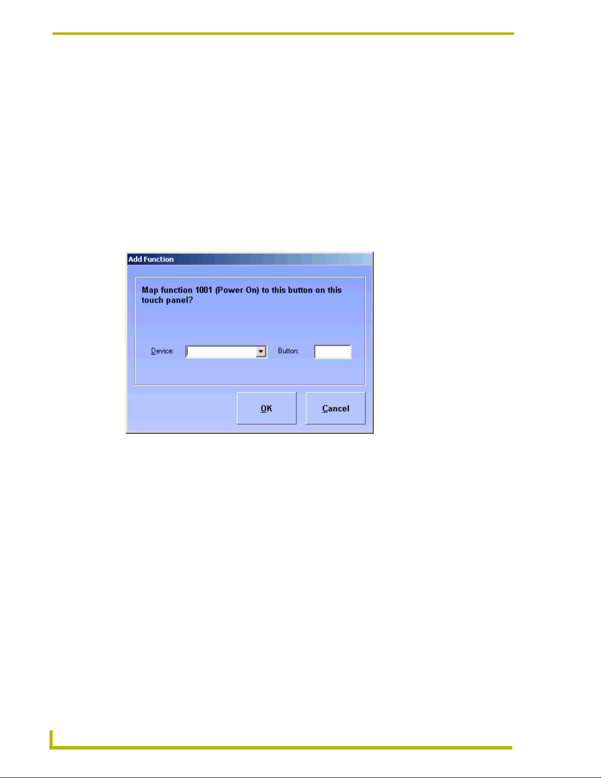
i!-ConnectLinx Touch Panel Button Mappings Page
The i!-ConnectLinx Touch Panel Button Mappings page is available if you selected
Support pre-meeting presets? or Monitor source usage? on the Room Information/Options page.
You can map touch panel buttons to i!-ConnectLinx. Otherwise, only power on/off and source
selects are available.
The i!-ConnectLinx functions grid list displays all i!-ConnectLinx functions, with touch panel
button mappings, currently available in the project. The column on the left contains a checkbox
where the check indicates the function is mapped. Removing the check clears the mapping.
RMS CodeCrafter
FIG. 25 i!-ConnectLinx Functions Page
Category - A list of i!-ConnectLinx function categories. The Functions list populates
corresponding to your selection in this list.
Functions - A list of i!-ConnectLinx functions for the selected category.
Touch Panel Device - A list of devices populated by what is defined in the integrated file.
Button - A numeric field for the button number.
Add - Adds an entry to the device list. Once you click add you are prompted with a confirmation
window. The window contains the current function number and name. The window provides a box
to select the touch panel device and a numeric field for the button number, but if the device and
35
Page 44
RMS CodeCrafter MeetingManager Project Pages
button fields are populated, RMS CodeCrafter will attempt to add the mapping without offering the
dialog.
In the event the mapping already exists, the mapping will fail and you receive a notification. To
re-map, the original must be removed from the device list.
Remove - Removes the device currently selected in the device list.
Previous - Regresses the RMS CodeCrafter wizard to the Device Parameters Page.
Next - Progresses the RMS CodeCrafter wizard to the Generate NetLinx Code File Page.
Edit Touch Panel Button-mappings
The Edit Touch Panel Button-mappings window allows you to edit the button-mappings.
Listed is the i!ConnectLinx function name and number. This field is static.
FIG. 26 Edit Touch Panel Button-mappings
Device - Drop down lists of devices available. This field is populated by devices extracted from the
integrated NetLinx file. You can select an existing device, enter a new device, or enter a D:P:S
address. If you select an existing device or enter a new device, a warning for the device is added to
the generated code file.
Panel Button Number - This is a text field you can edit to enter the panel button number.
OK - Accepts changes and closes window.
Cancel - Closes window and does not keep changes.
36
RMS CodeCrafter
Page 45
RMS CodeCrafter MeetingManager Project Pages
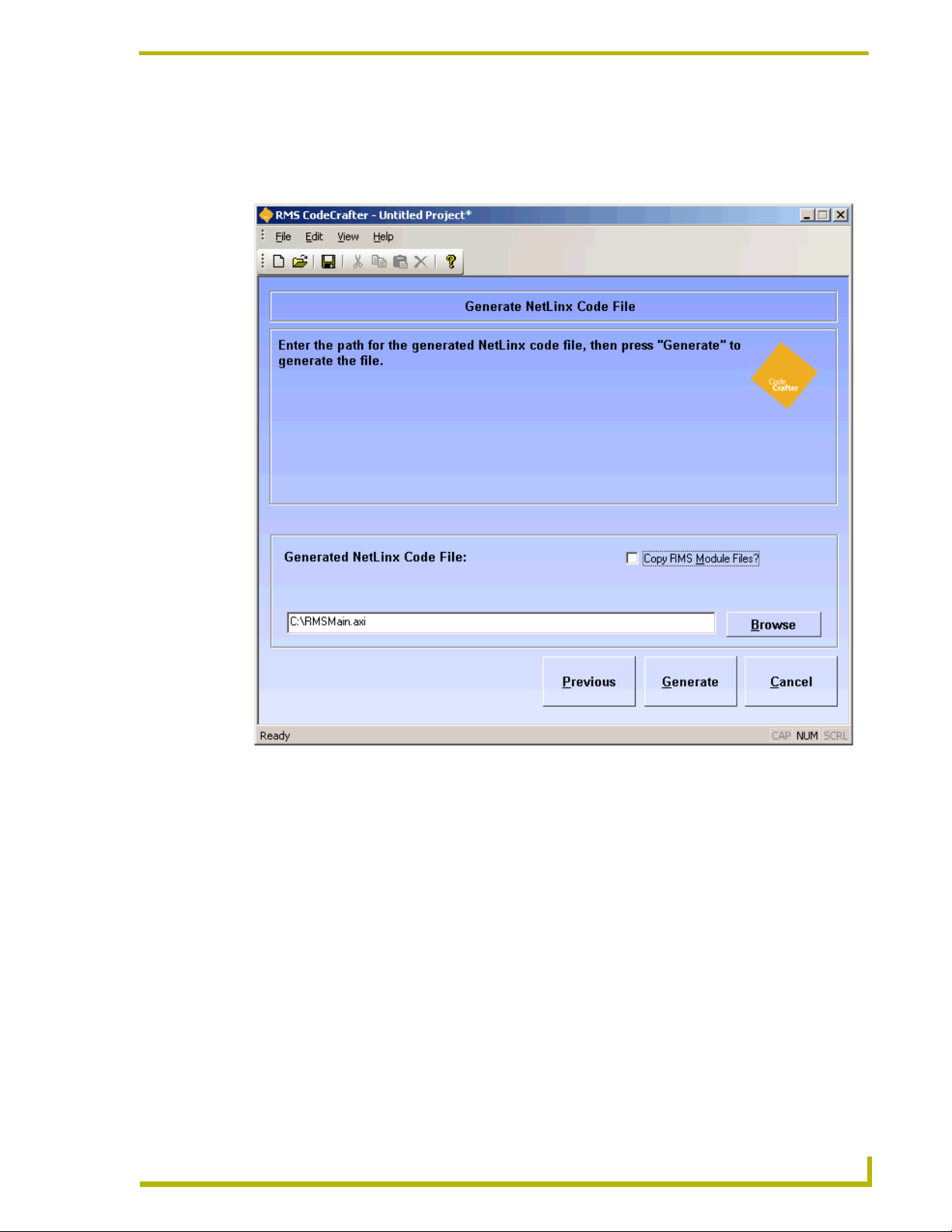
Generate NetLinx Code File Page
The Generate NetLinx Code File page prompts RMS CodeCrafter to generate the NetLinx include
code file.
RMS CodeCrafter
FIG. 27 Generate Code Page
Generated NetLinx Code File - This is a text field you can either type the path or click Browse
and specify the file name and target to generate.
Copy RMS Module Files? - When the box is checked, RMS CodeCrafter will copy all
corresponding .TKO files from the SDK install location and paste them in the location you
designated in the Generated NetLinx Code File path.
Previous - Regresses the RMS CodeCrafter wizard to the i!-ConnectLinx Touch Panel Button
Mappings page.
Generate - Prompts RMS CodeCrafter to generate the file and advance to the final page.
37
Page 46

RMS CodeCrafter MeetingManager Project Pages
Code Generation Wizard - Finished Page
The Code Generation Wizard - Finished page is the final step in the process of creating your own
RMS code. The results of the code generation operation and confirmation of the target location is
listed.
38
FIG. 28 Wizard Complete Page
Finish - Clicking this button returns you to the Introductory page. If you selected Save Project on
Finish? in User Preferences you are prompted to save your project now.
RMS CodeCrafter
Page 47

RMS CodeCrafter AssetManager Project Pages
RMS CodeCrafter AssetManager Project
Pages
Introductory Page
The Introductory page is the initial page displayed upon launching the RMS CodeCrafter wizard.
RMS CodeCrafter
FIG. 29 Introductory Page
The button you select will determine what file is generated. The buttons are as follows:
New Project - Opens a new RMS CodeCrafter project file (.CGP) and progresses to the Project
Start Page.
Open Project - After selecting the desired file in the open dialog window, it opens an existing RMS
CodeCrafter project file (.CGP) and progresses to the Project Start Page.
New Device Template - Opens a new RMS CodeCrafter template file (.CGT) and progresses to the
Device Template Main Page.
Open Device Template - After selecting the desired file in the open dialog window, it opens an
existing RMS CodeCrafter template file (.CGT) and progresses to the Device Template Main Page.
39
Page 48

RMS CodeCrafter AssetManager Project Pages
Additionally, you can set default features of the wizard with:
Edit Preferences - Launches the Preferences window.
Preferences Window
RMS CodeCrafter allows you to set user preferences.
FIG. 30 Preferences Window
Template Folder - A text field where you can either type or click Browse to designate the default
template folder destination.
Default R.M.S. Server Address - A text field where you can edit the server address for the R.M.S.
server. The default value is 0.0.0.0.
Generate Device Variable Warnings - A checkbox, when enabled adds variable warnings in the
generated code.
Save Project on Finish? - A checkbox, when enabled automatically saves your project when you
click the final Finish button.
OK - Accepts the changes and closes the preferences window.
Cancel - Closes the preferences window without incorporating the changes.
40
RMS CodeCrafter
Page 49

RMS CodeCrafter AssetManager Project Pages
Code Generation Wizard - Start Page
The Code Generation Wizard - Start page is the first page you see when you open a new or existing
project file.
RMS CodeCrafter
FIG. 31 Project Start Page
Select the appropriate RMS application - This is the RMS application code you want generated.
Click the radio button to select. Your choices are:
MeetingManager (default)
AssetManager
Enter the NetLinx code file (.AXS) or NetLinx Studio workspace file (.APW) to be integrated
into this project. - Either type or click the Browse button for the location of the file to be integrated
into the project. The file can be either a NetLinx code (.AXS) or NetLinx Studio workspace
(.APW) file. The incorporation of either file into a RMS CodeCrafter project is optional.
Next - Progresses RMS CodeCrafter to the next page.
41
Page 50

RMS CodeCrafter AssetManager Project Pages
Code File Selection Page
You will see the Code File Selection page if you selected a NetLinx Studio workspace file (.APW)
in the Project Start page. A list of all available NetLinx code files within the .APW file is displayed.
Previous - Returns the wizard back to the Project Start page.
Next - Progresses the RMS CodeCrafter wizard to the Room Information/Options page.
Room Information/Options Page
RMS CodeCrafter supports the ability to add scheduling and i!-ConnectLinx options to a project
file.
42
FIG. 32 Room Information/Options Page
i!-ConnectLinx Options:
Monitor source usage? - Placing a check in this box determines if the
RMSSourceUsageMod is defined in the generated code file.
Using multiple display devices? - This option is only available when Monitor source
usage? has been selected. Placing a check in this box determines if a call to
RMS CodeCrafter
Page 51

RMS CodeCrafter AssetManager Project Pages
RMSSetMultiSource(TRUE) is included in the DEFINE_EVENT section of the
generated code.
Room Name - A text field, you provide the name of the room. (This field is required)
Location - A text field, you provide the name of the location for the room. (This field is
required)
Owner - A text field, you provide the name of the person that owns the room. (This field
is required)
AssetManager Options:
Include Help Desk Code - If selected, RMS CodeCrafter will define RMSHelpUIMod in
the generated code. This option is only available if you selected AssetManager on the
Project Start Page.
Previous - Regresses the RMS CodeCrafter wizard to the Code File Selection page.
Next - Progresses the RMS CodeCrafter wizard to the RMS Server Address page.
RMS CodeCrafter
43
Page 52

RMS CodeCrafter AssetManager Project Pages
RMS Server Address Page
The RMS Server Address page allows you the opportunity to specify the IP address of the R.M.S.
server. This is optional and if left unchanged, the default specified in the Preferences window is
used.
44
FIG. 33 Server Address Page
R.M.S. Server Address - A text field where you can type the IP address of the R.M.S. server if
necessary.
Previous - Regresses the RMS CodeCrafter wizard to the Room Information/Options page.
Next - Progresses the RMS CodeCrafter wizard to the RMS Virtual and Socket Device Definitions
page.
RMS CodeCrafter
Page 53

RMS CodeCrafter AssetManager Project Pages
RMS Virtual and Socket Device Definitions Page
RMS Virtual and Socket Device Definitions page allows you to determine options related to i!-
ConnectLinx and Scheduling on the Scheduling And i!-ConnectLinx Options page.
RMS CodeCrafter
FIG. 34 RMS Devices Page
vdvRMSEngine - A text field you can edit and specify to meet your needs. The device, port and
socket location of the virtual device, RMS Engine.
dvRMSSocket - A text field you can edit and specify to meet your needs. The device, port and
socket location of the device, RMS Socket.
If these devices are defined in the integrated file, the fields are automatically populated and
protected.
i!-ConnectLinx virtual device:
vdvCLActions - A text field you can edit and specify to meet your needs. The device, port
and socket location of the virtual device, ConnectLinx.
If this device is defined in the integrated file, the fields are automatically populated and protected.
In the event the devices are not defined by the integrated file or there is no integrated file
for the project, the fields are populated by the following defaults:
45
Page 54

RMS CodeCrafter AssetManager Project Pages
vdvRMSEngine - 33001:1:0
dvRMSSocket - 0:3:0
vdvCLActions - 33002:1:0
Device definitions are added to the generated code file; otherwise, a warning statement is added in
the generated code file.
Previous - Regresses the RMS CodeCrafter wizard to the Server Address page.
Next - Progresses the RMS CodeCrafter wizard to the Help Desk: Display Panels page.
Help Desk: Display Panels Page
The Help Desk: Display Panels page allows you to add, edit and delete Help Desk functions used in
conjunction with AssetManager. The Help Desk page is only available if you selected Include Help
Desk Code on the Room Information/Options page.
46
FIG. 35 Help Desk: Display Panels Page
Add Panel - Launches the Add/Edit Help Desk Panel window. Adds a Help Desk panel to the
project.
RMS CodeCrafter
Page 55

RMS CodeCrafter AssetManager Project Pages
Edit Panel - Launches the Add/Edit Help Desk Panel window. When a Help Desk panel is selected
you can edit its properties.
The Help Desk panel grid lists all panels available for the project. Any entry not selected with a
check will be removed from the project upon closing the project.
Previous - Regresses the RMS CodeCrafter wizard to the RMS Virtual and Socket Device
Definitions page.
Next - Progresses the RMS CodeCrafter wizard to the Named NetLinx Devices page.
Add/Edit Help Desk Panel Window
RMS CodeCrafter
FIG. 36 Add/Edit Help Desk Panel Window
The Add/Edit Help Desk Panel window is available to add and edit panel information. The fields
you can edit are as follows:
Panel Size - A list of supported panel sizes supported by RMS CodeCrafter, click on your desired
panel size to select.
Description - A text field you can edit to describe the panel.
Base Device - Drop down lists of devices available. This field is populated by devices extracted
from the integrated NetLinx file. You can select an existing device, enter a new device, or enter a
D:P:S address. If you select an existing device or enter a new device, a warning for the device is
added to the generated code file.
MeetingManager Pages - Drop down lists of devices available. This field is populated by devices
extracted from the integrated NetLinx file. You can select an existing device, enter a new device, or
enter a D:P:S address. If you select an existing device or enter a new device, a warning for the
device is added to the generated code file.
47
Page 56

RMS CodeCrafter AssetManager Project Pages
Keyboard Device - Drop down lists of devices available. This field is populated by devices
extracted from the integrated NetLinx file. You can select an existing device, enter a new device, or
enter a D:P:S address. If you select an existing device or enter a new device, a warning for the
device is added to the generated code file.
OK - Accepts changes and closes window.
Cancel - Closes window and does not keep changes.
Named NetLinx Devices Page
The Named NetLinx Devices page allows you to add, edit and delete devices monitored as Named
Devices. A named device is a NetLinx device that supports a logical name, i.e., a touch panel.
48
FIG. 37 Named Devices Page
Add Device - Launches the Add/Edit Named Device window. Adds a named device to the project.
Edit Device - Launches the Add/Edit Named Device window. When a named device is selected
you can edit its properties.
Add all Welcome and Main Panels - Launches the Add All Welcome and Main Panels window.
Doing this adds all MeetingManager devices to the named device grid list.
RMS CodeCrafter
Page 57

RMS CodeCrafter AssetManager Project Pages
The named device grid lists all devices available for the project. Any entry not selected with a
check will be removed from the project upon closing the project.
Previous - Regresses the RMS CodeCrafter wizard to the Help Desk: Display Panels page.
Next - Progresses the RMS CodeCrafter wizard to the Monitored Third-Party Devices page.
Add/Edit Named Devices Window
FIG. 38 Add/Edit Named Devices Window
The Add/Edit Named Devices window is available to add and edit named devices. The fields you
can edit are as follows:
Device - Drop down lists of devices available. This field is populated by devices extracted from the
integrated NetLinx file. You can select an existing device, enter a new device, or enter a D:P:S
address. If you select an existing device or enter a new device, a warning for the device is added to
the generated code file.
Logical Name - A text field you can edit to name the device.
OK - Accepts changes and closes window.
Cancel - Closes window and does not keep changes.
RMS CodeCrafter
49
Page 58

RMS CodeCrafter AssetManager Project Pages
Add All Welcome and Main Panels Window
When you click Add all Welcome and Main Panels RMS CodeCrafter searches the existing Main
and Welcome panels for MeetingManager devices that are not already listed on the Named Devices
list. All devices found are compiled into a list and appear in the Add All Welcome and Main Panels
window. Within this window you can select any, all or none for your use. In the event no devices are
found, this window will inform you none were found.
The grid list is all MeetingManager devices found in the Main and Welcome panels. Any entry not
selected with a check is not included in the project. The Device column is the device name and the
Logical Name column is the associated name for that device. RMS CodeCrafter uses the panel
description for the logical name, it can be changed after you add it to the list (Add/Edit Named
Devices).
OK - Accepts changes and closes window.
Cancel - Closes window and does not keep changes.
Monitored Third-Party Devices Page
The Monitored Third-Party Devices page allows you to add, edit and delete devices intended to be
monitored as Monitored Devices. A Monitored Device is a device that supports a logical name,
manufacturer, and model, i.e., a projector.
50
FIG. 39 Monitored Devices Page
RMS CodeCrafter
Page 59

RMS CodeCrafter AssetManager Project Pages
Add Device - Launches the Add/Edit Monitored Device window. Adds a monitored device to the
project.
Edit Device - Launches the Add/Edit Monitored Device window. When a monitored device is
selected you can edit its properties.
Add Device from Template - Launches the Add Device from Template window. Adds a device
using a device template.
The monitored device grid lists all devices available for the project. Any entry not selected with a
check will be removed from the project upon closing the project.
Previous - Regresses the RMS CodeCrafter wizard to the Named NetLinx Devices Page.
Next - Progresses the RMS CodeCrafter wizard to the Device Parameters Page.
Add/Edit Monitored Devices Window
RMS CodeCrafter
FIG. 40 Add/Edit Monitored Devices Window
The Add/Edit Monitored Devices window is available to add and edit named devices. The fields
you can edit are as follows:
Device - Drop down lists of devices available. This field is populated by devices extracted from the
integrated NetLinx file. You can select an existing device, enter a new device, or enter a D:P:S
address. If you select an existing device or enter a new device, a warning for the device is added to
the generated code file.
51
Page 60

RMS CodeCrafter AssetManager Project Pages
Logical Name - A text field you can edit to name the device.
Manufacturer - This is a text field where you can provide the manufacturer information for the
device.
Model - This is a text field where you can provide the model information for the device.
Support Module - Click the radio button that best represents the device for the template.
Projector
Transport
Basic
Slide Projector
None
Using communications (COMM) module? - When selected, RMS CodeCrafter includes code for
a communications module.
Communications Module Virtual Deivce - A combo list either populated by virtual
communication devices or you can type your own virtual device in the field.
Module Virtual Device - Drop down lists of devices available. This field is populated by devices
extracted from the integrated NetLinx file. You can select an existing device, enter a new device, or
enter a D:P:S address. If you select None in Support Module, this control is disabled.
Communication Timeout - Measured in 1/10ths of a second, where 0 is a valid value. If no
timeout is required, use -1.
Control Failure Detect - Placing a check in the box adds a call to RMSEnablePowerFailure() in
the generated code file.
OK - Accepts changes and closes window.
Cancel - Closes window and does not keep changes.
52
RMS CodeCrafter
Page 61

RMS CodeCrafter AssetManager Project Pages
Add Device from Template Window
If you select Add Device from Template, this window gives you the selection of all templates found
in the default folder and populates them into the grid.
FIG. 41 Add Device from Template Window
Device - A list where you can either select the device or type it in manually.
Virtual Device - A list where you can either select the communications module virtual device or
type it in manually. This field is required only when the selected device template uses a
communications module.
Logical Name - A text field where you can type the logical name of the device.
OK - Accepts the changes and closes the window.
Cancel - Closes the window without keeping changes.
RMS CodeCrafter
53
Page 62

RMS CodeCrafter AssetManager Project Pages
Device Parameters Page
The Device Parameters page allows you to add, edit and delete Device Parameters.
54
FIG. 42 Device Parameters Page
Add Parameter - Launches the Add/Edit Device Parameters window. Adds a device parameter to
the project.
Edit Parameter - Launches the Add/Edit Device Parameters window. When a device parameter is
selected you can edit its properties.
The device parameters grid lists all devices available for the project. Any entry not selected with a
check will be removed from the project upon closing the project.
Previous - Regresses the RMS CodeCrafter wizard to the Monitored Third-Party Devices page.
Next - Progresses the RMS CodeCrafter wizard to the i!-ConnectLinx Touch Panel Button
Mappings page.
RMS CodeCrafter
Page 63

RMS CodeCrafter AssetManager Project Pages
Add/Edit Device Parameters Window
The Add/Edit Device Parameters window allows you to add device parameters or edit existing
ones.
FIG. 43 Add/Edit Device Parameters Window
Device - A list of devices available in this project. This field is populated by devices extracted from
the integrated NetLinx file or user defined devices within the project.
Name - A text field you can edit to name the parameter.
Type - Select one of the parameter types:
Number
Index
String
Enum
Status - select one from the scroll list:
Not Assigned
Room Communication
Control System
Network
Security
RMS CodeCrafter
55
Page 64

RMS CodeCrafter AssetManager Project Pages
Help Request
Maintenance
Equipment Usage
Threshold Hold - select from the following:
None
Less Than
Less Than or Equal To
Greater Than
Greater Than or Equal To
Equal To
Not Equal To
Contains (String or Enum only)
Does Not Contain (String or Enum only)
Val ue - A text field you can edit to set threshold value. 32-bit signed number for Number, 16-bit
unsigned number for Index and any string up to 100 characters for String and Enum.
Reset - Place a mark in the box to enable reset of threshold.
Reset Value - A text field you can edit to set reset value. 32-bit signed number for Number, 16-bit
unsigned number for Index and any string up to 100 characters for String and Enum.
Trigger - select one of the following:
None
Button
Channel
Level
Use Range (Number) - Sets the minimum and maximum for number; this value is optional.
Set Range (Enum or Index) - A drop down list of enumeration strings. You can elect to:
Add - adds the sting to the parameter use.
Remove - removes the string from parameter use.
Move Up - moves the string up the list of parameter use.
Move Down - moves the string down the list of parameter use.
56
OK - Closes the window and saves changes made.
Cancel - Closes window without implementing changes.
RMS CodeCrafter
Page 65

Set Range for Index or Enum Parameter
RMS CodeCrafter AssetManager Project Pages
FIG. 44 Set Range for Index or Enum Parameter
Add string - adds the sting to the parameter use.
Remove - removes the string from parameter use.
Move Up - moves the string up the list of parameter use.
Move Down - moves the string down the list of parameter use.
OK - Closes the window and saves changes made.
Cancel - Closes window without implementing changes.
RMS CodeCrafter
57
Page 66

RMS CodeCrafter AssetManager Project Pages
i!-ConnectLinx Touch Panel Button Mappings Page
The i!-ConnectLinx Touch Panel Button Mappings page is available if you selected Monitor source
usage? on the Room Information/Options page. You can map touch panel buttons to i!-
ConnectLinx. Otherwise, only power on/off and source selects are available.
The i!-ConnectLinx functions grid list displays all i!ConnectLinx functions, with touch panel
button mappings, currently available in the project. The column on the left contains a checkbox
where the check indicates the function is mapped. Removing the check clears the mapping.
58
FIG. 45 i!-ConnectLinx Functions Page
Category - A list of i!-ConnectLinx function categories. The Functions list populates
corresponding to your selection in this list.
Functions - A list of i!-ConnectLinx functions for the selected category.
Touch Panel Device - A list of devices populated by what is defined in the integrated file.
Button - A numeric field for the button number.
Add - Adds an entry to the device list. Once you click add you are prompted with a confirmation
window. The window contains the current function number and name. The window provides a box
to select the touch panel device and a numeric field for the button number, but if the device and
RMS CodeCrafter
Page 67

RMS CodeCrafter AssetManager Project Pages
button fields are populated, RMS CodeCrafter will attempt to add the mapping without offering the
dialog.
In the event the mapping already exists, the mapping will fail and you receive a notification. To
re-map, the original must be removed from the device list.
Remove - Removes the device currently selected in the device list.
Previous - Regresses the RMS CodeCrafter wizard to the Device Parameters page.
Next - Progresses the RMS CodeCrafter wizard to the Generate NetLinx Code File page.
Edit Touch Panel Button-mappings
The Edit Touch Panel Button-mappings window allows you to edit the button-mappings.
Listed is the i!ConnectLinx function name and number. This field is static.
FIG. 46 Edit Touch Panel Button-mappings
Device - Drop down lists of devices available. This field is populated by devices extracted from the
integrated NetLinx file. You can select an existing device, enter a new device, or enter a D:P:S
address. If you select an existing device or enter a new device, a warning for the device is added to
the generated code file.
Panel Button Number - This is a text field you can edit to enter the panel button number.
OK - Accepts changes and closes window.
Cancel - Closes window and does not keep changes.
RMS CodeCrafter
59
Page 68

RMS CodeCrafter AssetManager Project Pages
Generate NetLinx Code File Page
The Generate NetLinx Code File page prompts RMS CodeCrafter to generate the NetLinx include
code file.
60
FIG. 47 Generate Code Page
Generated NetLinx Code File - This is a text field you can either type the path or click Browse
and specify the file name and target to generate.
Copy RMS Module Files? - When the box is checked, RMS CodeCrafter will copy all
corresponding .TKO files from the SDK install location and paste them in the location you
designated in the Generated NetLinx Code File path.
Previous - Regresses the RMS CodeCrafter wizard to the i!-ConnectLinx Touch Panel Button
Mappings page.
Generate - Prompts RMS CodeCrafter to generate the file and advance to the final page.
RMS CodeCrafter
Page 69

RMS CodeCrafter AssetManager Project Pages
Code Generation Wizard - Finished Page
The Code Generation Wizard - Finished page is the final step in the process of creating your own
RMS code. The results of the code generation operation and confirmation of the target location is
listed.
RMS CodeCrafter
FIG. 48 Wizard Complete Page
Finish - Clicking this button returns you to the Introductory page. If you selected Save Project on
Finish? in User Preferences you are prompted to save your project now.
61
Page 70

RMS CodeCrafter AssetManager Project Pages
62
RMS CodeCrafter
Page 71

Basic Operations
Creating A New Device Template
You can create persistent templates for monitored devices, where you provide the settings and
parameters. RMS CodeCrafter can then use the device templates for similar or the same devices in
other projects.
1. With the RMS CodeCrafter wizard open to the Introductory page, click New Device
Template.
2. The RMS CodeCrafter wizard opens to the Device Template Main page.
3. Type the name of your Template in the field Template Name.
4. Type the manufacturer name in the field Manufacturer.
5. Type the model in the field Model.
6. Place a check in the box Uses Communications Module? if you would like to enable it for this
template.
7. Set a value for the Communications Timeout, measured in 1/10ths of a second, where 0 is a
valid value. If no timeout is required, use -1.
Basic Operations
8. If you want to enable Control Failure Detect, place a check in the box next to it.
9. Click the radio button for the Support Module that fits your device template.
Projector
Transport
Basic
Slide Projector
None
10. Click Next. The next page is Template Device Parameters page.
11. Click Add Parameter to launch the Add/Edit Device Template Parameters window.
12. Type the name of the parameter in the field provided.
13. Click the radio button for the Type of parameter and select the Status in the menu.
14. In the menu, select the Threshold Comparison and enter the Threshold Value. Place a check
next to Reset to enable.
15. Click the radio button for the Trigger type.
16. Based on the Type of parameter you selected in step 13 you may need to provide a range for the
parameter.
RMS CodeCrafter
17. Click Next. The next page is Device Template Wizard Finished page.
18. Within the Save Template to field, either type or click Browse to select the target location to
save your template file (.CGT).
19. Click Finish to create the template file and save it.
63
Page 72

Basic Operations
Creating A New AssetManager Project
The RMS CodeCrafter wizard creates project files that it uses in generating the NetLinx code you
need. To create a .CGP file:
1. From the Introductory page click New Project.
2. The next page is the Project Start page. Select your desired RMS application, AssetManager.
3. Either type or click Browse to select the location of your integrated file.
While it is not necessary to have either an .AXS or .AWP file to use the RMS
CodeCrafter wizard, it is advisable. The integrated file will populate several fields
throughout the wizard that you will need to otherwise enter manually.
4. Click Next.
If NetLinx Studio workspace file (.APW) is selected as the integrated file:
a. From the list of NetLinx code files listed in the Code File Selection page, click on
the desired file and click Next.
If NetLinx Studio workspace file (.APW) was not selected as the integrated file:
b. The next page is Scheduling and i!-ConnectLinx options page. Check all
i!-ConnectLinx Options that apply.
5. Place a check to enable:
Support pre-meeting presets?
Monitor source usage?
Using multiple display devices?
6. Define the Room Name, Location, Owner.
7. Place a check next to Include Help Desk Code to enable it.
8. Click Next. The next page is RMS Server Address page.
9. Type the R.M.S. Server Address in the field provided or leave blank to use the default.
10. Click Next. The next page is RMS Virtual and Socket Device Definitions page.
11. Type all D:P:S fields that apply.
12. Click Next. The next page is Help Desk: Display Panels (if selected on the Room Information/
Options page) Named NetLinx Devices (if Help Desk was not selected).
If Include Help Desk Code was selected
To add a Help Desk panel, click Add Panel and open the Add/Edit Help Desk Panel
window. To edit a panel, select the panel from the list and click Edit Panel to open the
Add/Edit Help Desk Panel window.
Once you have added all of your main panels, click Next. The next page is Named
NetLinx Devices.
64
13. To add a device, click Add Device and open the Add/Edit Named Device window. To edit a
device, select the device from the list and click Edit Device to open the Add/Edit Named
Device window. If you would like to find and add all MeetingManager devices not already in
RMS CodeCrafter
Page 73

Basic Operations
the Named Devices list, click Add all Welcome and Main Panels to launch the Add All
Welcome and Main Panels Window.
14. Once you have included all of your named devices for your project, click Next. The next page
is Monitored Third-Party Devices page.
15. To add a device, click Add Device and open the Add/Edit Monitored Device window. To edit a
device, select the device from the list and click Edit Device to open the Add/Edit Monitored
Device window. You can also add a device from a template, click Add Device from Template
to open the Add Device from Template window.
If you selected Add Device from Template, select the device from the list. Either type or
enter the Device, Virtual Device, and Logical Name. Click OK.
16. Once you have included all of your monitored devices for your project, click Next. The next
page is Device Parameters.
17. To add a device parameter, click Add Device and open the Add/Edit Device Parameters
window. To edit a device parameter, select the device from the list and click Edit Device to
open the Add/Edit Device Parameters window.
18. Once you have included all of your device parameters for your project, click Next. The next
page is i!-ConnectLinx Touch Panel Button Mappings.
19. To edit an i!-ConnectLinx entry, select the function from the list and click Edit Function to
open the Edit Touch Panel Button-mappings.
20. Once you have included all of your button-mappings for your project, click Next. The next
page is Generate NetLinx Code File.
21. Either type the file name and target destination or click Browse and specify the location. Once
you have entered the information, click Generate.
22. The next and final page is Code Generation Wizard - Finished. You will see this page if the
NetLinx include file was successfully created. Displayed within the page is the file name and
target destination.
23. Click Finish.
RMS CodeCrafter
65
Page 74

Basic Operations
Creating A New MeetingManager Project
The RMS CodeCrafter wizard creates project files that it uses in generating the NetLinx code you
need. To create a .CGP file:
1. From the Introductory page click New Project.
2. The next page is the Project Start page. Select your desired RMS application, AssetManager.
3. Either type or click Browse to select the location of your integrated file.
While it is not necessary to have either an .AXS or .AWP file to use the RMS
CodeCrafter wizard, it is advisable. The integrated file will populate several fields
throughout the wizard that you will need to otherwise enter manually.
4. Click Next.
If NetLinx Studio workspace file (.APW) is selected as the integrated file:
a. From the list of NetLinx code files listed in the Code File Selection page, click on
the desired file and click Next.
If NetLinx Studio workspace file (.APW) was not selected as the integrated file:
b. The next page is Scheduling and i!-ConnectLinx options page. Check all
i!-ConnectLinx Options that apply.
5. Select your i!-ConnectLinx Options:
Support pre-meeting presets?
Monitor source usage?
Using multiple display devices?
6. Define the Room Name, Location, Owner.
7. Click the radio button to select one of the following Scheduling Displays:
Main and welcome panels
Welcome panels only
No scheduling display
8. Click Next. The next page is RMS Server Address page.
9. Type the R.M.S. Server Address in the field provided or leave blank to use the default.
10. Click Next. The next page is RMS Virtual and Socket Device Definitions page.
11. Type all D:P:S fields that apply.
12. Click Next. The next page is Scheduling: Main Panels page.
13. To add a panel, click Add Panel and open the Add/Edit Main Panel window. To edit a panel,
select the panel from the list and click Edit Panel to open the Add/Edit Main Panel window.
66
14. Once you have added all of your main panels, click Next. If you selected either Main and
Wel c om e Pan el s or Welcome panels only in step 7 the next page is Scheduling: Welcome
Panels page. Otherwise it is Named NetLinx Devices page.
Main and welcome panels or Welcome panels only selected:
RMS CodeCrafter
Page 75

Basic Operations
15. To add a panel, click Add Panel and open the Add/Edit Welcome Panel window. To edit a
panel, select the panel from the list and click Edit Panel to open the Add/Edit Welcome Panel
window.
16. Once you have added all of your main panels, click Next. The next page is Named NetLinx
Devices.
No scheduling display selected:
17. To add a device, click Add Device and open the Add/Edit Named Device window. To edit a
device, select the device from the list and click Edit Device to open the Add/Edit Named
Device window. If you would like to find and add all MeetingManager devices not already in
the Named Devices list, click Add all Welcome and Main Panels to launch the Add All
Welcome and Main Panels Window.
18. Once you have included all of your named devices for your project, click Next. The next page
is Monitored Third-Party Devices page.
19. To add a device, click Add Device and open the Add/Edit Monitored Device window. To edit a
device, select the device from the list and click Edit Device to open the Add/Edit Monitored
Device window. You can also add a device from a template, click Add Device from Template
to open the Add Device from Template window.
If you selected Add Device from Template, select the device from the list. Either type or
enter the Device, Virtual Device, and Logical Name. Click OK.
20. Once you have included all of your monitored devices for your project, click Next. The next
page is Device Parameters.
21. To add a device parameter, click Add Device and open the Add/Edit Device Parameters
window. To edit a device parameter, select the device from the list and click Edit Device to
open the Add/Edit Device Parameters window.
22. Once you have included all of your device parameters for your project, click Next. The next
page is i!-ConnectLinx Touch Panel Button Mappings.
23. To edit an i!-ConnectLinx entry, select the function from the list and click Edit Function to
open the Edit Touch Panel Button-mappings.
24. Once you have included all of your button-mappings for your project, click Next. The next
page is Generate NetLinx Code File.
25. Either type the file name and target destination or click Browse and specify the location. Once
you have entered the information, click Generate.
26. The next and final page is Code Generation Wizard - Finished. You will see this page if the
NetLinx include file was successfully created. Displayed within the page is the file name and
target destination.
27. Click Finish.
RMS CodeCrafter
67
Page 76

Basic Operations
Saving A Device Template File
Once you have created a Device Template it is necessary to save it order to keep changes made.
1. With the Device Template open, select File > Save.
2. Select the target location for the file and click Save.
Saving A Project File
Once you have created a RMS CodeCrafter file, it is necessary to save the file. You can then return
to the file at a later date.
1. With the project file open, select File > Save.
2. Select the target location to save the file.
3. Click Save.
Opening An Existing Device Template
You can create persistent templates for monitored devices, where you provide the settings and
parameters. RMS CodeCrafter can then use the device templates for similar or the same devices in
other projects.
If you already created a template, you can open and use it following these steps:
1. With RMS CodeCrafter wizard open to the Introductory page, click Open Device Template to
launch the Open RMS CodeCrafter Device Template window.
2. Select the template file (.CGT) you would like to use and click Open.
3. The wizard opens to Device Template Main page.
Follow these steps to edit your template:
1. Type the name of your Template in the field Template Name.
2. Type the manufacturer name in the field Manufacturer.
3. Type the model in the field Model.
4. Set a value for the Communications Timeout, measured in 1/10ths of a second, where 0 is a
valid value. If no timeout is required, use -1.
5. If you want to enable Control Failure Detect, place a check in the box next to it.
6. Click the radio button for the Support Module that fits your device template.
Projector
Transport
Basic
Slide Projector
68
None
7. Click Next. The next page is Device Template Final page.
8. Within the Save Template to field, either type or click Browse to select the target location to
save your template file (.CGT).
9. Click Finish to create the template file and save it.
RMS CodeCrafter
Page 77

Basic Operations
Opening An Existing Project
If you have already created a project (.CGP) and would like to use it as a starting point, follow these
steps:
1. With the RMS CodeCrafter wizard open to the Introductory page, click Open Project.
2. In the Open RMS CodeCrafter Project window, navigate to your project and click Open.
You can now begin working from your saved project.
Closing A Project Or Template File
Once you are done with a project or template file, but would like to keep RMS CodeCrafter open,
you can close the file. To close a file:
Select File > Close. If you have not already saved your file you are prompted to do so at
this time.
Importing RMS SDK Spreadsheets
Earlier releases of RMS SDK utilized an Excel spreadsheet that RMS CodeCrafter now replaces.
You can import your device and parameter information from the Excel spreadsheet into RMS
CodeCrafter.
1. Select File > Open > Import Spreadsheet.
2. Browse to your desired .XLS file and click Open.
RMS CodeCrafter
69
Page 78

Basic Operations
SERVERINFO.TXT Window
RMS CodeCrafter allows you to generate a text file, SERVERINFO.TXT, that contains the IP
address of the RMS server, and then transfer the file to the RMS directory on the system master for
the room.
FIG. 49 SERVERINFO.TXT Window
R.M.S. Server Address (or Hostname) - A text field for entering either the IP address or
hostname of the RMS server.
System Master Address - A text field for entering either the IP address or hostname of the master
controller for the room.
Username - A text field for entering the FTP username on the master controller for the room.
Password - A text field for entering the FTP password on the master controller for the room.
Send - Creates the text file, places the file in the Temp directory, attempts file transfer and then
deletes the file upon successful transfer.
Close - Closes the window without saving and no action taken.
70
RMS CodeCrafter
Page 79

Basic Operations
Exiting RMS CodeCrafter
You've created a device template, implemented said template into a project file and then used RMS
CodeCrafter to generate the inclusion file code. Now you would like to close the project file and
exit RMS CodeCrafter.
Select File > Exit. If you have not already saved you are prompted to do so at this time.
Adjusting RMS CodeCrafter
Changing Visual Style
To change the appearance of RMS CodeCrafter:
Select View > Visual Styles and select from the following
Default
Office XP®
Office 2003®
Web Update
Newer versions of RMS CodeCrafter can now be acquired via the internet. The Web Update utility
accesses the AMX web site with the application ID and version number and searches for updates.
1. Go to Help > Web Update to check for updates.
2. If updates are available for the installed version of RMS CodeCrafter they are downloaded at
this time.
3. After the download is complete Web Update closes RMS CodeCrafter and the updates are
added.
If you do not have Web Update installed, you receive a window indicating where it can be
downloaded.
Setting Template Folder Destination
You can create persistent templates for monitored devices, where you provide the settings and
parameters. RMS CodeCrafter can then use the device templates for similar or the same devices in
other projects.
RMS CodeCrafter will only look in this folder destination for devices, and templates are saved in
this target location by default. If you save your templates in a location other than what is listed here,
RMS CodeCrafter will not find them.
1. With RMS CodeCrafter open to the Introductory page, click Edit Preferences to open the
Preferences window.
2. In the Template Folder field, either type or click Browse to set the target location.
3. Click OK.
RMS CodeCrafter
71
Page 80

Basic Operations
Setting Default R.M.S. Server Address
As part of the code generated by RMS CodeCrafter, the IP address of the RMS server can be
included. The IP address is necessary when using Scheduling and i!-ConnectLinx options.
To set the location RMS CodeCrafter uses:
1. With RMS CodeCrafter open to the Introductory page, click Edit Preferences to open the
Preferences window.
2. Type the IP address of the RMS server in the field, Default R.M.S. Server Address.
3. Click OK.
Setting Wizard to Generate Device Variable Warnings
RMS CodeCrafter generates an inclusion code file. You can designate if you want Device Variable
Warnings listed in the code file. By default the warnings are enabled, to disable:
1. With RMS CodeCrafter open to Introductory page, click Edit Preferences to open the
Preferences window.
2. Click the checkbox next to Generate Device Variable Warnings to remove the check.
3. Click OK.
72
RMS CodeCrafter
Page 81

Code Generation
RMS CodeCrafter will output a single, all-inclusive NetLinx include (.axi) file, with the following
features:
File Header
RMS CodeCrafter should include a header including an AMX copyright notice, an RMS SDK
version, and information about the RMS CodeCrafter program such as name and version.
(***************************************************************************)
(* AMX Corporation *)
(* Copyright (c) 2004 AMX Corporation. All rights reserved. *)
(***************************************************************************)
(* please refer to EULA.TXT for software license agreement *)
(***************************************************************************)
(* *)
(* AMX Resource Management Suite (2.0.13) *)
(* *)
(***************************************************************************)
RMS CodeCrafter obtains the RMS SDK version by reading a registry key set by the SDK installer,
HKEY_LOCAL_MACHINE\SOFTWARE\AMX Corp.\RMS SDK\Version.
Code Generation
DEFINE_DEVICES Section
Device definitions
RMS CodeCrafter will generate device definitions for the following devices in the
DEFINE_DEVICE section of the generated file, if they cannot be located in the integrated source
file:
vdvRMSEngine – the RMS Engine virtual device
dvRMSEngine – the socket device for communication with the RMS server
vdvCLActions – the i!-ConnectLinx virtual device.
vdvKB – A virtual device for communicating with the KeyboardMod module. This will
only be defined if the KeyboardMod is defined.
The values used in these definitions are those entered on the RMS Devices wizard page.
Device Definition Warnings
For all other devices referenced in the code-generation process, RMS CodeCrafter will optionally
create warnings that notify the user that the device has not been defined. Below is one such
warning:
// dvTP3a
#IF_NOT_DEFINED dvTP3a
#WARN 'RMS: This Device Needs to be Defined in your Main Program: dvTP3a'
#END_IF
An option will be provided to enable/disable these warnings. By default they are enabled.
RMS CodeCrafter
73
Page 82

Code Generation
DEFINE_CONSTANT Section
Server Address Definition
RMS CodeCrafter will create a definition for the server address, using the value provided in the
RMS Server Address Page.
// RMS Server IP
CHAR RMS_SERVER_IP[100] = '192.168.222.51'
Maximum String/Enum Param Length
RMS CodeCrafter will create a definition for RMS_MAX_PARAM_LEN constant, with a value of
100.
// Max String/Enum Param Length
RMS_MAX_PARAM_LEN = 100
RMSCommon.axi
RMS CodeCrafter will create an include statement for the RMSCommon.axi include file. This will
be inserted after the DEFINE_CONSTANT section and prior to the DEFINE_VARIABLE section.
(***********************************************************)
(* INCLUDE FILES GO BELOW *)
(***********************************************************)
#INCLUDE 'RMSCommon.axi'
DEFINE_VARIABLE Section
Device Arrays
Main Panels
RMS CodeCrafter creates a device array for all Main Panels. This array is used as a parameter to
the RMSUIMod and RMSHelpUIMod modules. This array is created only if the user selects Main
and Welcome Panels under Scheduling Options, or selects the Include Help Desk Code option
(AssetManager only).
RMS CodeCrafter adds G3 panels first, followed by G4 panels. A comment regarding the order of
G3 panels is placed before the list.
// RMS Devices
// If a G3 panel appears first in this list, then G3 compatible
commands will be used.
// If a G4 panel appears first in this list, then G4 commands will be
used (looks better).
VOLATILE DEV dvRMSTP[] =
{
dvTP1a
}
Wel c ome Panel s
RMS CodeCrafter creates a device array for all Welcome Panels. This array is used as a parameter
to the RMSUIMod and/ or RMSWelcomeOnlyUIMod module. This array is created only if the user
selects either Main and Welcome Panels or Welcome Panels Only under Scheduling Options.
74
RMS CodeCrafter adds G3 panels first, followed by G4 panels. A comment regarding the order of
G3 panels is added before the list.
// RMS Welcome Devices
// If a G3 panel appears first in this list, then G3 compatible
commands will be used.
RMS CodeCrafter
Page 83

Code Generation
// If a G4 panel appears first in this list, then G4 commands will be
used (looks better).
VOLATILE DEV dvRMSTPWelcome[] =
{
dvTP2a
}
Keyboard Panels
RMS CodeCrafter should create a device array for all Main Panels Base (string) devices. This array
is used as a parameter to the RMSUIMod, RMSHelpUIMod, and KeyboardMod modules. This
array is created only if the user selects Main and Welcome Panels under Scheduling Options, or
selects the Include Help Desk Code option (AssetManager only).
// RMS Keyboard Devices
VOLATILE DEV dvRMSKeyboard[] =
{
dvTP1a
}
Keyboard Channel Arrays
RMS CodeCrafter creates three channel arrays, nchKBControl, nchKBFields and nvtKBFields, for
parameters to KeyboardMod if KeyboardMod is included. These arrays should include the default
values for the channels used by the RMS touch panel pages as shown below. These arrays will be
created only if the user selects Main and Welcome Panels under Scheduling Options.
// Keyboard Insert and Auto Shift
VOLATILE INTEGER nchKBControl[] =
{
79, // Insert
80, // Auto Shift
81, // OK
82 // Cancel
}
// Keyboard Fields for direct select
VOLATILE INTEGER nchKBFields[]=
{
78 // Field 1
}
// Keyboard Fields for direct select
VOLATILE INTEGER nvtKBFields[]=
{
78 // Field 1
}
RMS CodeCrafter
i!-ConnectLinx variables
String and Level parameters
RMS CodeCrafter creates variables to hold string and level parameters from i!-ConnectLinx if the
i!-ConnectLinx module is included. These variables are arrays and have a length of three (3) to
support standard i!-ConnectLinx functions. These arrays will only be included if Pre-Meeting
Presets and/or Monitor Source are selected in the i!-ConnectLinx Options page.
// i!-ConnectLinx parameter storage
VOLATILE SLONG asnNumberLevelArgValues[3]
VOLATILE CHAR acStringEnumArgValues[3][50]
Channel Arrays
RMS CodeCrafter creates two channel arrays for i!-ConnectLinx if i!-ConnectLinx/touch panel
button mapping has been defined.
// i!-ConnectLinx Standard Actions
VOLATILE INTEGER nchCLButtons[] =
75
Page 84

Code Generation
{
1002 // Power Off
// i!-ConnectLinx Touch Panel Buttons
VOLATILE INTEGER nchCLPanelButtons[] =
{
1 // Power Off
}
Device Parameters
RMS CodeCrafter creates a variable for each device parameter specified, of the following types:
Number – Signed Long (SLONG)
Index – Integer (INTEGER)s
String – String (CHAR Array), length is RMS_MAX_PARAM_LEN
Enum– String (CHAR Array), length is RMS_MAX_PARAM_LEN
Each variable name will contain one of the following Hungarian prefixes, based on type:
Signed Long (SLONG) – sl
Integer (INTEGER) – n
CHAR array – c
The name itself will be constructed as follows:
<prefix> + “RMS” + <device logical name> + <parameter name>
Each variable definition will be defined as VOLATILE.
Each variable definition will be preceded on the line above it by a comment containing its
corresponding device’s name. Each definition will be immediately followed on the same line with a
comment containing the parameter name, like so:
// dvLProj
VOLATILE SLONG slRMSLeftProjectorLampHours // Lamp Hours
76
RMS CodeCrafter
Page 85

Code Generation
Function Definitions
RMSCommon Callbacks
RMS CodeCrafter creates definitions for the following callback functions:
RMSDevMonRegisterCallBack
This function has the following signature:
(***************************************)
(* Call Name: RMSDevMonRegisterCallback*)
(* Function: time to register devices *)
(* Param: None *)
(* Return: None *)
(* Note: Caller must define this *)
(***************************************)
DEFINE_FUNCTION RMSDevMonRegisterCallback()
{
}
Each monitored device and parameter not monitored with a support module will add several lines
of code within this function.
A comment containing the devices logical name
A call to RMSRegisterDevice()
A call to RMSRegisterDeviceNumberParam()
RMSDevMonSetParamCallBack
This function has the following signature:
(***************************************)
(* Call Name: RMSDevMonSetParamCallback*)
(* Function: Reset parameters *)
(* Param: DPS, Name, Value *)
(* Return: None *)
(* Note: Caller must define this *)
(***************************************)
DEFINE_FUNCTION RMSDevMonSetParamCallback(DEV dvDPS, CHAR cName[], CHAR
cValue[])
{
}
Each device parameter with Reset selected should have an entry in an ACTIVE/CASE statement.
Further, all parameters of the same device will be grouped in the same ACTIVE/CASE statement.
As in the following example:
SELECT
{
// Left Projector
ACTIVE (dvLProj == dvDPS):
{
IF ('Lamp Hours' == cName)
slLeftProjectorLampHours = ATOI(cValue)
}
}
RMS CodeCrafter
77
Page 86

Code Generation
RMS Device Parameters
A custom function will be generated for each parameter to set the value of the parameter and report
it to the RMS server. This function will follow the following structure:
(*******************************************)
(* Call Name: RMSSetLeftProjectorLampHours *)
(* Function: Set Lamp Hours *)
(* Param: Value *)
(* Return: None *)
(*******************************************)
DEFINE_FUNCTION RMSSetLeftProjectorLampHours(SLONG slValue)
LOCAL_VAR
CHAR bInit
{
IF (slRMSLeftProjectorLampHours <> slValue || bInit = FALSE)
RMSChangeNumberParam(dvLProj,'Lamp Hours',RMS_PARAM_SET,slValue)
slRMSLeftProjectorLampHours = slValue
bInit = TRUE
}
Module Definitions
RMS CodeCrafter generates the following module definitions in the DEFINE_START section.
Monitored Device/Support Modules
RMS CodeCrafter generates a module definition for each Monitored device that uses a Support
Module. Each module declaration is created using the Module name, the monitored devices virtual
and actual device names, and the RMS Engine’s virtual device name (vdvRMSEngine).
Each module definition is preceded by a comment containing the device name of the monitored
device.
Source Usage
This module definition is generated if the user selects Monitor Source Usage in the i!-ConnectLinx
Options page.
// RMSSrcUsageMod - Tracks equipment usage.
DEFINE_MODULE 'RMSSrcUsageMod' mdlSrcUsage(vdvRMSEngine,
vdvCLActions)
RMS Engine
This module definition is always generated boilerplate.
// RMSEngineMod - The RMS engine. Requires i!-ConnectLinxEngineMod.
DEFINE_MODULE 'RMSEngineMod' mdlRMSEng(vdvRMSEngine,
dvRMSSocket,
vdvCLActions)
RMSUIMod
This module definition is generated if the user selects Main and Welcome Panels in the Scheduling
Options.
// RMSUIMod - The RMS/MeetingManager User Interface. Requires KeyboardMod.
// Channel And Variable Text Code Defined Inside The Module
DEFINE_MODULE 'RMSUIMod' mdlRMSUI(vdvRMSEngine,
vdvKB,
dvRMSKeyboard,
dvRMSTP,
dvRMSTPWelcome)
78
RMS CodeCrafter
Page 87

Code Generation
RMSWelcomeOnlyUIMod
This module definition is generated if the user selects Welcome Panels Only in the Scheduling
Options.
// RMSWelcomeOnlyUIMod - The RMS/MeetingManager Welcome Panel User Interface.
// Channel And Variable Text Code Defined Inside The Module
DEFINE_MODULE 'RMSWelcomeOnlyUIMod' mdlRMSUI(vdvRMSEngine,
dvRMSTPWelcome)
KeyboardMod
This module definition is generated if the user selects Main and Welcome Panels in the Scheduling
Options, or if the user selects AssetManager as the RMS application, and enables the Include Help
Desk Code option.
// KeyboardMod - Provides Keyboard Management.
DEFINE_MODULE 'KeyboardMod' mdlKB(vdvKB,
dvRMSKeyboard,
dvRMSTP,
nchKBControl,
nchKBFields,
nvtKBFields)
i!-ConnectLinxEngineMod
This module definition is generated if the user selects Pre-Meeting Presets and/or Monitor Source
Usage in the i!-ConnectLinx Options page.
// i!-ConnectLinxEngineMod
DEFINE_MODULE 'i!-ConnectLinxEngineMod' mdlCL(vdvCLActions)
RMSHelpUIMod (AssetManager only)
This module definition is generated if the user selects AssetManager as the RMS application, and
enabled the Include Help Desk Code option.
// RMSHelpUIMod - The RMS/AssetManager Help Desk Interface. Requires
KeyboardMod.
DEFINE_MODULE 'RMSHelpUIMod' mdlRMSHelpUI(vdvRMSEngine,
vdvKB,
dvRMSKeyboard,
dvRMSTP)
RMS CodeCrafter
79
Page 88

Code Generation
Event Definitions
RMS CodeCrafter generates the following DATA_EVENT blocks the DEFINE_EVENT section.
RMS Engine Device
RMS CodeCrafter generates a DATA_EVENT block for the RMS Engine device. This block will
always be generated, boilerplate, with these exceptions:
If the Use Multiple Displays option is selected, RMS CodeCrafter will generate a call to
RMSSetMultiSource(TRUE)
A call to RMSSetDeviceInfo() will be generated for each monitored device using an
RMS Support Module; If the device has a non-negative timeout value, a call to
RMSSetCommunicationTimeout() will be generate.; Finally, if the device has Detect
Control failure enabled, a call to RMSEnablePowerFailure will be generated.
See the example block below:
(*******************************************)
(* DATA: RMS Engine *)
(*******************************************)
DATA_EVENT[vdvRMSEngine]
{
ONLINE :
{
// Configure RMS Server Address
RMSSetServer(RMS_SERVER_IP)
// Track Multiple Sources
RMSSetMultiSource(TRUE)
// Display
RMSSetDeviceInfo(dvProj,'Display','Display Manufacturer','Display Model')
RMSSetCommunicationTimeout(dvProj,200)
RMSEnablePowerFailure(dvProj)
}
}
Named Devices
RMS CodeCrafter generates a DATA_EVENT block for each Named Device. This block will
always be generated as follows:
(*******************************************)
(* DATA: Main Touch Panel *)
(*******************************************)
DATA_EVENT [dvTP1a]
{
ONLINE:
RMSNetLinxDeviceOnline(dvTP1a,'Main Touch Panel')
OFFLINE:
RMSNetLinxDeviceOffline(dvTP1a)
}
80
RMS CodeCrafter
Page 89

Code Generation
Monitored Devices
RMS CodeCrafter generates a DATA_EVENT block for each Monitored Device not using a
support module. This block will always be generated as follows:
(*******************************************)
(* DATA: Left Projector *)
(*******************************************)
DATA_EVENT [dvLProj]
{
ONLINE:
{
// Register Device and Parameters
RMSRegisterDevice(dvLProj,'Left Projector','Manufacturer','Model')
RMSRegisterDeviceNumberParam(dvLProj,'Lamp
Hours',1000,RMS_COMP_GREATER_THAN,RMS_STAT_MAINTENANCE,TRUE,0,RMS_PARAM_SET,sl
RMSLeftProjectorLampHours,0,0)
}
OFFLINE:
RMSNetLinxDeviceOffline(dvLProj)
}
Device Parameters
RMS CodeCrafter generates an event handler for each device parameter of BUTTON. LEVEL, or
CHANNEL type. See the RMS CodeCrafter Requirements specification for an example.
i!-ConnectLinx
RMS CodeCrafter generates an DATA_EVENT block for the i!-ConnectLinx virtual device. If Pre-
Meeting Presets is selected, a LEVEL_EVENT block will also be created. Additionally, a
BUTTON_EVENT and a CHANNEL_EVENT should be included to connect i!-ConnectLinx
buttons to touch panel buttons.
LEVEL_EVENT Block
This block is of fixed format and is generated as follows. It does not make use of the i!-
ConnectLinx variables defined in the variables section.
(*******************************************)
(* LEVEL: i!-ConnectLinx Engine *)
(*******************************************)
LEVEL_EVENT[vdvCLActions,0]
{
// Store it if we have room
IF (MAX_LENGTH_ARRAY(asnNumberLevelArgValues) >= LEVEL.INPUT.LEVEL)
asnNumberLevelArgValues [LEVEL.INPUT.LEVEL] = LEVEL.Value
}
RMS CodeCrafter
81
Page 90

Code Generation
DATA_EVENT Block
RMS CodeCrafter generates a DATA_EVENT block for the vdvCLActions virtual device. This
block will create the following:
A fixed format STRING parsing block
A SEND_COMMAND statement to register the room name, owner, and location.
Registration commands for each function-touch panel button mapping. These registration
commands can be combined using the AND and THROUGH syntax.
An example block is provided below:
(*******************************************)
(* DATA: i!-ConnectLinx Engine *)
(*******************************************)
DATA_EVENT[vdvCLActions]
{
STRING:
{
STACK_VAR
CHAR cTemp[1000]
CHAR cTrash[10]
INTEGER nId
// Look for arguments
IF (LEFT_STRING(DATA.TEXT,3) = 'ARG')
{
// Get arg ID
cTemp = DATA.Text
cTrash = REMOVE_STRING(cTemp,'ARG',1)
nId = ATOI(cTemp)
cTrash = REMOVE_STRING(cTemp,'-',1)
// Store it if we have room
IF (MAX_LENGTH_ARRAY(acStringEnumArgValues) >= nId)
acStringEnumArgValues [nId] = cTemp
}
}
ONLINE:
{
// Set Room Info
SEND_COMMAND DATA.DEVICE,'SET ROOM INFO-MeetingManager Sample,Richardson
TX,AMX Corp.'
// Configure by Macros
SEND_COMMAND DATA.DEVICE,'ADD MACRO-power'
SEND_COMMAND DATA.DEVICE,'ADD MACRO-dvd'
SEND_COMMAND DATA.DEVICE,'ADD MACRO-cd'
SEND_COMMAND DATA.DEVICE,'ADD MACRO-lights'
SEND_COMMAND DATA.DEVICE,'ADD MACRO-blinds'
// System Controls
// Power Off (1002)
// Select VHS (1011)
// Select DVD (1014)
// Select Video Conference (1017)
// Select Rack Computer (1021)
// Select Aux PC Input (1022)
// Select Slide (slide to video) (1024)
// Select CD Player (1042)
SEND_COMMAND DATA.DEVICE,'ADD STD-1002&1011&1014&1017&1021-1022&1024&1042'
// Lighting
// Lights All Off (1061)
// Lights All On (1062)
// Lights Meeting Mode (1063)
// Lights Presentation Mode (1064)
// Lights Conference Mode (1065)
82
RMS CodeCrafter
Page 91

SEND_COMMAND DATA.DEVICE,'ADD STD-1061-1065'
// Blinds
// Blinds Open (1095)
// Blinds Close (1096)
SEND_COMMAND DATA.DEVICE,'ADD STD-1095-1096'
// VCR - VHS
// VCR Play (1131)
// VCR Stop (1132)
// VCR Pause (1133)
// VCR Fast Forward (1134)
// VCR Rewind (1135)
// VCR Search Fwd (1136)
// VCR Search Rev (1137)
SEND_COMMAND DATA.DEVICE,'ADD STD-1131-1137'
// DVD
// DVD Play (1221)
// DVD Stop (1222)
// DVD Pause (1223)
// DVD Skip Forward (1224)
// DVD Skip Back (1225)
// DVD Search Fwd (1226)
// DVD Search Rev (1227)
SEND_COMMAND DATA.DEVICE,'ADD STD-1221-1227'
// CD Player
// CD Play (1731)
// CD Stop (1732)
// CD Pause (1733)
// CD Skip Forward (1734)
// CD Skip Back (1735)
// CD Search Fwd (1736)
// CD Search Rev (1737)
SEND_COMMAND DATA.DEVICE,'ADD STD-1731-1737'
}
}
Code Generation
BUTTON_EVENT Block
RMS CodeCrafter generates a BUTTON_EVENT block for each device with button mappings. It
does not make use of the i!-ConnectLinx variables defined in the variables section. An example
block is provided below.
(*******************************************)
(* BUTTON: i!-ConnectLinx Engine *)
(*******************************************)
BUTTON_EVENT[vdvCLActions,nchCLButtons]
{
PUSH:
DO_PUSH(dvTP1a,nchCLPanelButtons[GET_LAST(nchCLButtons)])
}
RMS CodeCrafter
83
Page 92

Code Generation
CHANNEL_EVENT Block
RMS CodeCrafter generates a CHANNEL_EVENT block for each device with button mappings. It
does not make use of the i!-ConnectLinx variables defined in the variables section. An example
block is provided below.
(*******************************************)
(* CHANNEL: i!-ConnectLinx Feedback *)
(*******************************************)
CHANNEL_EVENT[dvTP1a,nchCLPanelButtons]
{
ON:
ON[vdvCLActions,nchCLButtons[GET_LAST(nchCLPanelButtons)]]
OFF:
OFF[vdvCLActions,nchCLButtons[GET_LAST(nchCLPanelButtons)]]
}
84
RMS CodeCrafter
Page 93

RMS Concepts
Device Monitoring Framework
RMS provides device monitoring through a user extensible framework. This framework allows you
to customize what devices are monitored, the conditions that indicate a problem or fault and what
type of problem or fault this condition represents. RMS generates notifications when a fault
condition occurs, as determined by the notification configuration.
Each room has one or more monitored devices. Each device can be a physical device, such as a
video projector, or a logical device, like the RMS software. However, each monitored device must
be associated with a NetLinx-connected device. In the case of a video projector, this device would
be the IR card, Serial Card or IP Socket used to communicate with the projector. The RMS software
is associated with the NetLinx master itself.
Each monitored device has one or more device parameters that represent monitored items. For
instance, monitoring lamp hours of a video projector is accomplished through a "Lamp Hours"
parameter that belongs to the "Video Projector" device. All parameters must be associated with a
device.
RMS Concepts
In order to monitor a device, the NetLinx system must register the device and one or more
parameters with RMS. For instance, monitoring of Lamp Hours of the Video Projector is only
available if the NetLinx system has added the appropriate code. In many cases, this is as simple as
adding a RMS support module.
Device Values
Each monitored device has a set of values used in its description. These values are supplied when
the device is registered and consist of the following:
Device Values
Device Number This is the device number of the device, as defined in the NetLinx program. Devices are
Name This is the name of device. This name is displayed on the administrators console and
Manufacturer This is the manufacturer of the device. If this value is not supplied during registration, the
Model This is the model number of the device. If this value is not supplied during registration, the
Device Type This is the device type of the NetLinx-connected device. This might be "NI-2000" or
Serial Number This is the serial number of the NetLinx-connected Device. This is only available for
Firmware Version This is the firmware version of the NetLinx-connected device. This is only available for
tracked by Device ID so this value must be unique within the devices of a given room. For
instance, you can have multiple "1:1:0" devices as long as there is only 1:1:0" device per
room.
readily identifies the device.
manufacturer of the NetLinx-connected device will be used.
model name of the NetLinx-connected device will be used.
"NXP-TPI/4 Touch Panel". This is available for Axcess and NetLinx devices. This
information is registered automatically by the RMS server.
NetLinx devices. This information is registered automatically by the RMS server.
NetLinx devices. This information is registered automatically be the RMS server.
RMS CodeCrafter
85
Page 94

RMS Concepts
Device Values (Cont.)
Address and
Address Type
This is the physical address and address type for the Netlinx-connected device. This
information describes how the device is connected to the NetLinx master. A device
connected via ICSNet will display "ICSNet" for the address type and the hardware's
network address for the address. A device connected via IP will display "TCP/IP" for the
address type and the IP address for the address. Axcess devices will display "AXLink" for
both values. This information may be useful for diagnosing device connectivity problems.
This information is registered automatically by the RMS server.
Parameter Values
Each parameter has a set of values used to determine what conditions indicate a problem and what
type of problem this condition represents. These values are supplied when the parameter is
registered and consist of the following:
Parameter Values
Name This is the name of parameter. This name is displayed on the RMS server console
Parameter Type This value indicates if this value is a number or a string. This information is used to
Value and Units This is the current value of the parameter. Units are appended to the value when
Threshold Value and
Comparison Operator
Status Type The status represents the type of problem a faulted condition represents. Status
and readily identifies the parameter. Parameters are tracked by name so this name
must be unique within the parameters of a given device. For instance, you can have
multiple "Lamp Hours" parameters as long as there is only one "Lamp Hours"
parameter per monitored device.
determine how to perform certain operation, such as addition and comparisons
between the new and threshold values. For instance, comparing "10" and '2" as
strings results in "10" less than "2" but comparing them as numbers results in "2"
less than "10".
displayed in the web console.
The threshold value is the value for which this parameter is considered to indicate a
problem or fault. The comparison operator is used to detect when the value
changes from the un-faulted to the faulted condition. The comparison operators
"Less Than", "Less Than or Equal To", "Greater Than", "Greater Than or Equal To",
"Equal To" and "Not Equal To" can be used for strings and number parameters. The
comparison operators "Contains" and "Does Not Contain" are primarily used for
string parameters.
For example, "Lamp Hours" might have a threshold value of 1000 and any value
over this would require maintenance. The comparison operator would then be
"Greater Than". When this parameter changes from a value that is not greater than
1000 to a value that is greater than 1000, the fault status is set. When the value
changes from a value greater than 1000 to a value not greater than 1000, the fault
status is cleared. These value are supplied during registration but can be modified
by the administrator from the RMS server console.
Types include "Help Request", "Maintenance Request", "Room Communication
Error", "Control System Error", "Network Error", "Security" and "Equipment Usage."
For example, when "Lamp Hours" changes from an un-faulted (not greater than
1000) to a faulted (greater than 1000), this change represents a "Maintenance
Request" status that requires an AV technician to repair the equipment. If the
"Device Online" parameter changes from "Online" to "Offline", this change could
represent a "Security" or "Control System Error" status.
These value are supplied during registration but can be modified by the
administrator from the RMS server console.
86
RMS CodeCrafter
Page 95

RMS Concepts
Parameter Values (Cont.)
Reset Flag and Reset
Val ue
Minimum and Maximum
Values
Enumeration List This value is used to restrict the range of the threshold and reset values that the
These values determine if and how the parameter can be reset from the RMS
server console. If the Reset Flag is set, then the administrator can reset the value
remotely. When the administrator selects "Reset" from the console, the Reset Value
is copied to the Value and the faulted condition is cleared. These values are useful
for parameters such as VCR "Run Time" which would be manually reset when the
VCR is cleaned.
These values are used to restrict the range of the threshold and reset values that
the administrator can enter on the RMS server console. These values would be
used when the parameter represents a value with a bounded range, such as a
Vol u m e L evel .
administrator can enter on the RMS server console. This value would be used
when the parameter represents a value with a bounded list, Power On and Power
Off.
All parameters must be registered by the NetLinx system. The administrator cannot add parameters
from the RMS console. The administrator can modify Threshold Value, Comparison Operator and
Status Type for any parameter. This provides the administrator with the ability to set their own
threshold and re-classify messages based on their facility. For instance, an administrator can set the
Video projector's "Lamp Hours" threshold to the expected lamp life of a newly replaced lamp or
change the "Device Communicating" parameter from a "Control System Error" to a "Security"
status if the projector is in danger of being stolen.
Status Types
RMS supports the following status types for device monitoring: "Help Request", "Maintenance
Request", "Room Communication Error", "Control System Error", "Network Error", "Security"
and "Equipment Usage."
While there are no firm rules for what these status types mean and how they are used, AMX
provides the following description of each status type and recommends that your usage is consistent
with these descriptions.
Status Types
Help Request A user generated help request such as a help button on the touch panel.
Maintenance Request A user or monitored equipment generated maintenance request. Maintenance
issues would include items that require a technician to visit the room.
Room Communication Error A loss of communication between the room and the RMS server.
Control System Error Any error that represents a control system error, such as an offline device or
Network Error Any network related error. These would most commonly be associated with loss
Security Any security related issue. It might be appropriate to classify issues that might
Equipment Usage Any issue that does not require repair or maintenance and that is mainly used
loss of communication with a device.
of communication with devices that communicate via IP.
normally be classified as Control System or Network errors as Security issues
instead. This might include a touch panel going offline or loss of communication
with a projector depending on the physical security of these devices.
for status.
RMS CodeCrafter
87
Page 96

RMS Concepts
RMS SDK And RMS CodeCrafter
The RMS SDK consists of a series of modules to simplify device monitoring programming. Device
monitoring module handles the registration of devices and parameters and keeping track of lamp
hours and transport run time. In most cases, adding device monitoring is achieved by selecting the
appropriate device monitoring module and adding code to inform the module of important device
changes. The RMS support modules register and monitor the following parameters:
Basic Device (RMSBasicDeviceMod):
Device Online/Offline, Power, Communication Status for Serial devices, Control Failure
(Optional), IP Address of Socket-based devices.
Projector (RMSProjectorMod):
Device Online/Offline, Power, Lamp Hours, Communication Status for Serial devices, Control
Failure (Optional), IP Address of Socket-based devices.
Transport (RMSTransportMod):
Device Online/Offline, Power, Run Time, Communication Status for Serial devices, Control Failure
(Optional), IP Address of Socket-based devices.
Slide Projector (RMSSldProjMod):
Device Online/Offline, Power, Lamp Hours
88
RMS CodeCrafter
Page 97

i!-ConnectLinx
i!-ConnectLinx™ is an application that allows you to expose NetLinx™ actions to the outside
world. i!-ConnectLinx allows a programmer to define and program actions that can be utilized by
other user interfaces or processes outside the NetLinx Control System. For instance,
i!-ConnectLinx can be programmed to expose source select functions and i!-ConnectLinx
compatible technologies, such as i!-PCLink/PresentationControl
allow the source selects to be executed from a Microsoft PowerPoint
i!-ConnectLinx also provides a mechanism to request actions to be executed on the NetLinx
Control System. Once a process outside the NetLinx Control System has obtained the action list,
the process can then make a request to i!-ConnectLinx to execute that action. i!-ConnectLinx
handles this request and makes this request available to the NetLinx program for execution.
i!-ConnectLinxEngineMod, is the main i!-ConnectLinx module that handles exposing and
executing action requests. To support i!-ConnectLinx, you simply include this module in your
program, define your actions and write programming to support those actions. The
i!-ConnectLinxEngineMod module makes the list of actions available to other processes, executes
their requests and provides your program with a push when an action needs to be executed.
i!-ConnectLinx
™
, can use this information to
®
presentation.
Using i!-ConnectLinx
Little work is required to add i!-ConnectLinx to your existing NetLinx code. i!-ConnectLinx is
implemented as a NetLinx module. Adding the module definition and all it’s parameters to your
code is all that is required.
In order to use i!-ConnectLinx, you need to program and define a series of actions in the NetLinx
Control System. The key to the i!-ConnectLinx engine is the virtual device,
Support the actions you want executed remotely using this virtual device.
Think of the virtual device, vdvCLActions, as a touch panel. Normally, you write your NetLinx
program to respond to certain push channel from a touch panel; i!-ConnectLinx is exactly the same.
Let’s say you want the user to be able to allow i!-PCLink/PresentationControl the ability to play
and stop a VCR. Imagine you have two touch panel buttons that do these functions; write code that
responds to the pushes:
BUTTON_EVENT[TP,1] (* VCR Play *)
{
PUSH:
{
PULSE[VCR,1]
}
}
BUTTON_EVENT[TP,2] (* VCR Stop *)
{
PUSH:
{
PULSE{VCR,2]
}
}
vdvCLActions.
RMS CodeCrafter
To expose these actions using i!-ConnectLinx, write the same code substituting the touch panel
device for your i!-ConnectLinx virtual device:
89
Page 98

i!-ConnectLinx
BUTTON_EVENT[vdvCLActions,1] (* VCR Play *)
{
PUSH:
{
PULSE[VCR,1]
}
}
BUTTON_EVENT[vdvCLActions,2] (* VCR Stop *)
{
PUSH:
{
PULSE{VCR,2]
}
}
When the i!-ConnectLinx engine gets a request to play the VCR, i!-ConnectLinx will "push" the
button of the virtual device just like a user pushes a button on a touch panel. There is now only one
thing left to do: Tell the user which actions are which.
In order to expose an action for execution via i!-ConnectLinx, you need to support the
programming for the action, as we have just seen, and you need to tell i!-ConnectLinx what that
action is.
To specify the name of an action, send a command to the i!-ConnectLinx virtual device describing
the name of a given channel code. To specify the names of the actions in the above example, you
would add some code like this:
DATA_EVENT[vdvCLActions]
{
ONLINE:
{
(* Setup actions *)
(* VCR Play *)
SEND_COMMAND vdvCLActions,"'ADD ACTION-1,VCR Play"
(* VCR Stop *)
SEND_COMMAND vdvCLActions,"'ADD ACTION-2,VCR Stop' "
}
Once i!-ConnectLinx receives these commands, it stores this information in an XML file that can
be used by i!-ConnectLinx compatible technologies to browse available actions.
In addition to specifying the name of an action, you can also supply a help string and a folder name.
The help string helps a user understand the intent of the action more clearly. The folder name
allows you to organize the actions in a tree view so that actions are more easily browsed.
90
RMS CodeCrafter
Page 99

Code Generation
RMS CodeCrafter
91
Page 100

AMX reserves the right to alter specifications without notice at any time.
ARGENTI NA • AUST RALIA • BELGIUM • BRAZIL • CANADA • CHINA • ENGLAN D • FRANC E • GERMA NY • GRE ECE • HO NG KONG • INDIA • I NDONES IA • ITALY • JAPAN
LEBANON • MALAYSIA • MEXICO • NETHERLANDS • NEW ZEALAND • PHILIPPINES • PORTUGAL • RUSSIA • SINGAPORE • SPAIN • SWITZERLAND • THAILAND • TURKEY • USA
ATLANTA • BOSTON • CHICAG O • CLEVELAND • DAL LAS • DENVER • INDIANAPOLIS • LOS ANGELES • MINNEAPOLIS • PHILADELPHIA • PHOENIX • PORTLAND • SPOKANE • TAMPA
3000 RESEARCH DRIVE, RICHARDSON, TX 75082 USA • 800.222.0193 • 469.624.8000 • 469-624-7153 fax • 800.932.6993 technical support • www.amx.com
2004 AMX Corporation. All rights reserved. AMX, the AMX logo, the building icon, the home icon, and the light bulb icon are all trademarks of AMX Corporation.
©
033-004-2846 12/04
In Canada doing business as Panja Inc.
REV: A Last Revision: 13/12/04
 Loading...