

Page 1
PTM-D15
Platinum Series
15" Multimedia Touch Panel
instruction manual
To u c h Panels and Accessories
Page 2

AMX Limited Warranty and Disclaimer
AMX Corporation warrants its products to be free of defects in material and workmanship under normal use for
three (3) years from the date of purchase from AMX Corporation, with the following exceptions:
• Electroluminescent and LCD Control Panels are warranted for three (3) years, except for the display and touch
overlay components that are warranted for a period of one (1) year.
• Disk drive mechanisms, pan/tilt heads, power supplies, MX Series products, and KC Series products are
warranted for a period of one (1) year.
• Unless otherwise specified, OEM and custom products are warranted for a period of one (1) year.
• Software is warranted for a period of ninety (90) days.
• Batteries and incandescent lamps are not covered under the warranty.
This warranty extends only to products purchased directly from AMX Corporation or an Authorized AMX Dealer.
AMX Corporation is not liable for any damages caused by its products or for the failure of its products to perform.
This includes any lost profits, lost savings, incidental damages, or consequential damages. AMX Corporation is not
liable for any claim made by a third party or by an AMX Dealer for a third party.
This limitation of liability applies whether damages are sought, or a claim is made, under this warranty or as a tort
claim (including negligence and strict product liability), a contract claim, or any other claim. This limitation of
liability cannot be waived or amended by any person. This limitation of liability will be effective even if AMX
Corporation or an authorized representative of AMX Corporation has been advised of the possibility of any such
damages. This limitation of liability, however, will not apply to claims for personal injury.
Some states do not allow a limitation of how long an implied warranty last. Some states do not allow the limitation or
exclusion of incidental or consequential damages for consumer products. In such states, the limitation or exclusion of
the Limited Warranty may not apply. This Limited Warranty gives the owner specific legal rights. The owner may
also have other rights that vary from state to state. The owner is advised to consult applicable state laws for full
determination of rights.
EXCEPT AS EXPRESSLY SET FORTH IN THIS WARRANTY, AMX CORPORATION MAKES NO
OTHER WARRANTIES, EXPRESSED OR IMPLIED, INCLUDING ANY IMPLIED WARRANTIES OF
MERCHANTABILITY OR FITNESS FOR A PARTICULAR PURPOSE. AMX CORPORATION
EXPRESSLY DISCLAIMS ALL WARRANTIES NOT STATED IN THIS LIMITED WARRANTY. ANY
IMPLIED WARRANTIES THAT MAY BE IMPOSED BY LAW ARE LIMITED TO THE TERMS OF THIS
LIMITED WARRANTY.
Page 3

Table of Contents
Table of Contents
Safety Instructions ...................................................................................................a
FCC Compliance ............................................................................................................... b
Platinum Touch Panel ..............................................................................................1
Platinum Package Components........................................................................................ 1
Specifications .................................................................................................................... 2
PTM-D15 Rear Components............................................................................................. 5
PTM-D15 Sample Configuration ....................................................................................... 6
Installation and Wiring .............................................................................................7
Setting up the Panel .......................................................................................................... 7
Table Top Installation (PTM-D15) ..................................................................................... 7
Installing the Table Top support bracket .................................................................................. 7
Connecting the cables on a PTM-D15 panel ........................................................................... 9
Using the VGA IN DB-15 (male) high-density connector ......................................................... 9
Connecting to Optional Components .............................................................................. 10
Configuration and Setup ........................................................................................13
PTM-D15 Startup and Setup Procedures........................................................................ 13
Rear Panel buttons ................................................................................................................ 13
Setting Up Serial Communication from PC to the TPI/3.................................................. 14
Setting Up Serial procedures ................................................................................................. 14
Using AxcessX for serial communication ............................................................................... 14
Using HyperTerminal for serial communication ..................................................................... 15
Setting up the PTM-D15 touch device ................................................................................... 16
Setting the Output Resolution ................................................................................................ 17
Calibrating the Monitor ........................................................................................................... 18
Setting Up AXlink Communication from Master to the TPI/3........................................... 18
Setting Up AXlink procedures ................................................................................................ 18
Using AXCESSX for AXlink communication .......................................................................... 19
Using HyperTerminal for AXlink communication.................................................................... 19
Setting up the PTM-D15 touch device through AXlink ........................................................... 19
Setting Up NetLinx Communication from PC to the TPI/3............................................... 20
Using NetLinx Studio for communication via an Ethernet connection.................................... 20
Using NetLinx Studio for communication via an COM Port.................................................... 22
On Screen Display (OSD) Features .......................................................................25
On Screen Display (OSD) Icons...................................................................................... 25
Exiting the OSD............................................................................................................... 26
TM-D15 15" Platinum Touch Panel
i
Page 4

Table of Contents
Auto Tuning the Panel..................................................................................................... 26
Selecting the Language of the OSD................................................................................ 26
Adjusting Audio Volume .................................................................................................. 26
Adjusting Screen Brightness and Contrast ..................................................................... 27
Adjusting Display Performance (Clock and Phase) ........................................................ 27
Adjusting Horizontal and Vertical Screen Position .......................................................... 28
Selecting the Picture Color Temperature ........................................................................ 28
Adjusting Display Color (Red, Green, Blue).................................................................... 29
Adjusting OSD Menu Parameters (OSD Position and Timer)......................................... 29
Adjusting the Picture Sharpness ..................................................................................... 30
Automatic Contrast Adjustment (Auto Contrast) ............................................................. 31
Optimizing Picture Performance in DOS (Graphic/Text)................................................. 31
Returning (RECALL) to Factory Default Settings............................................................ 32
Exiting/Saving the OSD................................................................................................... 32
Troubleshooting .....................................................................................................33
Display Troubleshooting.................................................................................................. 33
Warning Messages and their Meanings.......................................................................... 34
ii
PTM-D15 15" Platinum Touch Panel
Page 5
Safety Instructions
Safety Instructions
1. Installation:
! Do not cover or block the ventilation holes in the case.
! Do not install the monitor near heat sources such as radiators/air ducts, or in a place
subject to direct sunlight, excessive dust, mechanical vibration or shock.
2. Warning on power connection - Use the pre-packaged power cord for connection to the rear
of the panel. The outlet should be installed near the monitor and be easily accessible.
! Do not allow anything to rest on the power cord.
! Disconnect the power plug from the power outlet under following conditions:
! If you are using it for an indefinite period time.
! When the power cord or plug is damaged.
! If the product has been dropped or the cabinet has been damaged.
! If the product exhibits a distinct change in performance, indicating a need for
service.
3. Maintenance:
! Clean the cabinet, glass, and controls with a soft cloth lightly moistened with a mild
detergent solution. Do not use any type of abrasive pad, scouring powder or solvent such
as alcohol or benzene.
! Do not rub, touch, or tap the surface of the screen with sharp or abrasive items such as a
pen or a screwdriver. This type of contact may result in scratched glass.
PTM-D15 15" Platinum Touch Panel
a
Page 6

Safety Instructions
! Do not insert sharp objects or spill liquid into the monitor through ventilation holes. This
may cause accidental fire, electric shock, or failure.
! Do not attempt to service this product yourself, as opening or removing covers may
expose you to dangerous voltages or other risks.
4. Transportation:
! When you transport this monitor for repair or shipment, use the original carton and
packing materials.
FCC Compliance
This device complies with Part 15 of the FCC Rules. Operation is subject to the following two
conditions: (1) this device may not cause harmful interference, and (2) this device must accept any
interference received, including interference that may cause undesired operation.
NOTE: This equipment has been tested and found to comply with the limits for a Class B digital
device, pursuant to Part 15 of the FCC Rules. These limits are designed to provide reasonable
protection against harmful interference in a residential installation. This equipment generates, uses
and can radiate radio frequency energy and, if not installed and used in accordance with the
instructions, may cause harmful interference to radio communications. However, there is no
guarantee that interference will not occur in a particular installation. If this equipment does cause
harmful interference to radio or television reception, which can be determined by turning the
equipment off and on, the user is encouraged to try to correct the interference by one or more of the
following measures:
! Re-orient or relocate the receiving antenna.
! Increase the separation between the equipment and receiver.
! Connect the equipment to an outlet on a circuit different from that to which the receiver is
connected.
! Consult the dealer or an experienced radio/TV technician for help.
Any unauthorized modification to this equipment will result in the revocation of
the authorization to operate the equipment and void the product warranty.
b
PTM-D15 15" Platinum Touch Panel
Page 7
Platinum Touch Panel
The 15" Platinum Table Top Panel (PTM-D15) comes ready-to-install and ready-to-use.
The PTM-D15 provides an impressive blend of vivid color graphics, sharp icons and seamless
video. The touch input works via a serial device, such as a serial mouse or touch monitor. This
system can be expanded by purchasing an optional AXB-TPI/3 with additional TPI/3 modules such
as the TP3-VGA (Graphics), TP3-RGB (RGB input), and TP3-VID (video) cards. The TPI/3
allows the use of any combination of these three cards.
Platinum Package Components
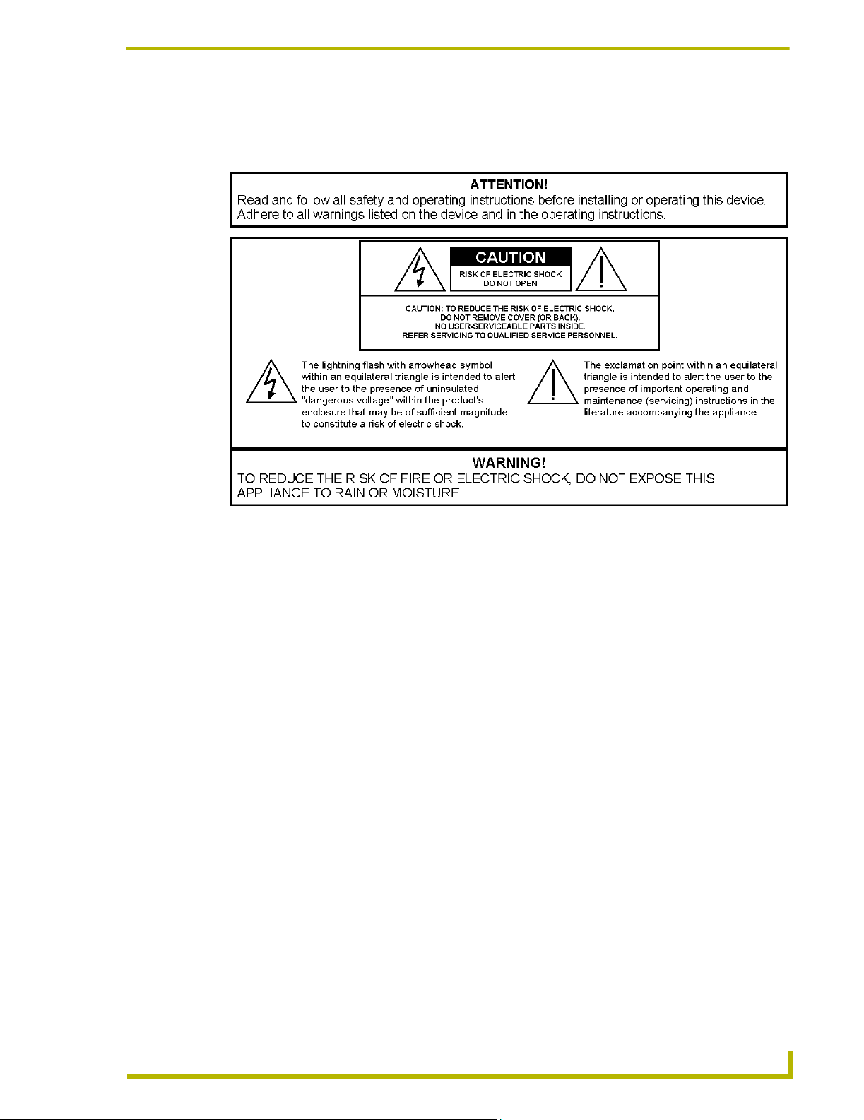
PTM-D15 15" Platinum Touch Panel
This panel is available in a Table Top (PTM-D15) version. This
touch panel has a wide viewing angle, crisp color with quality
depth/contrast, a +
panel allow a +
screen overlay. It receives a VGA signal through either a
Composite or S-Video connector port on the optional TPI/3.
160° viewable area, track wheels under the
360° base swivel, and an enhanced touch
Platinum Touch Panel
Powe r Adapter
Connects to the power cord in order to supply power to the
PTM-D15 touch panel.
Powe r Cord
Connects to the power adapter in order to supply power to the
PTM-D15/A touch panel.
15-pin DB15 VGA Signal Cable
Provides a video signal from the video source to the rear of
the PTM-D15 touch panel.
Cont.
TM-D15 15" Platinum Touch Panel
1
Page 8
Platinum Touch Panel
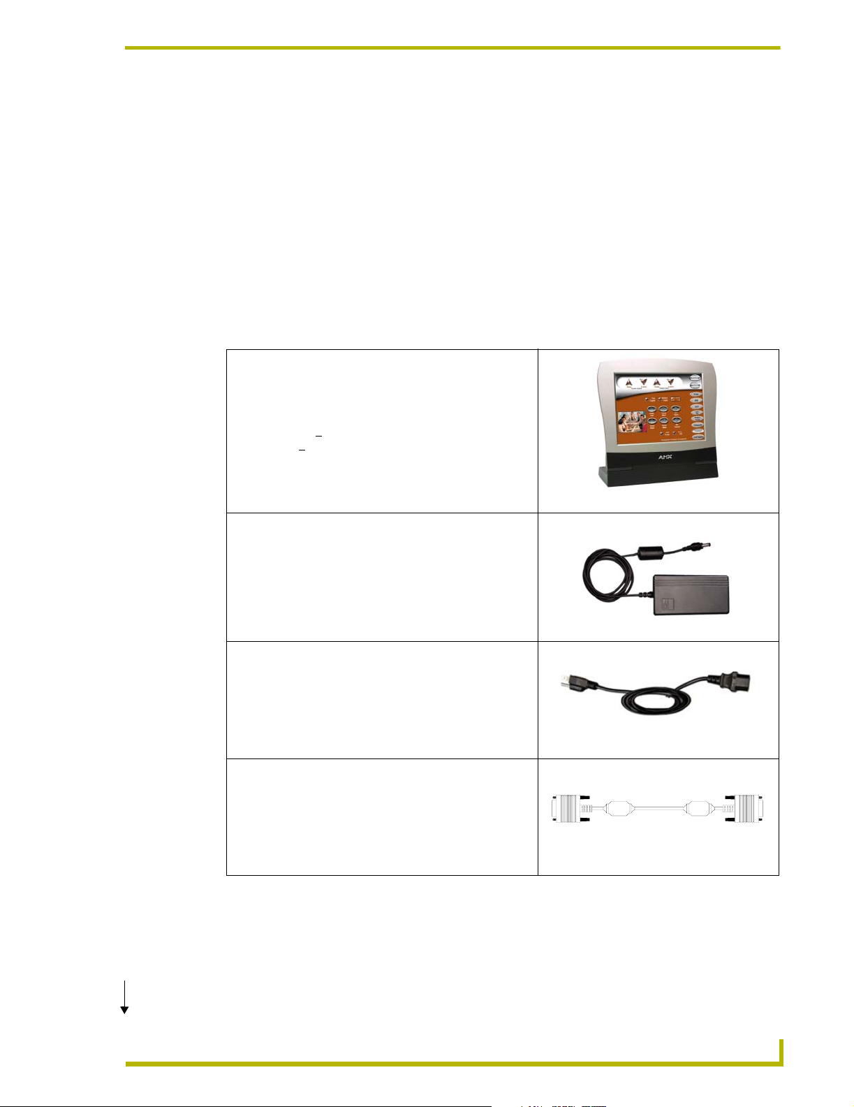
8-pin Mini Din to 9-pin DB9 Touch Panel Signal Cable
Provides a touchscreen signal from the PTM-D15 touch panel
to the panel interface.
Touch Screen Support Bracket and screws
Provides upright support for the PTM-D15 touch panel when
placed on a flat level surface.
USB Cable
Used to provide communication between the panel and the
USB port on the video source.
Audio Cable
Provides audio output connection between the panel and
external speakers.
DB-9 (on COM1/2)
8-pin mini-DIN
(on rear of panel)
Specifications
The following table lists the specifications of the PTM-D15 and describes the front and rear panel
components.
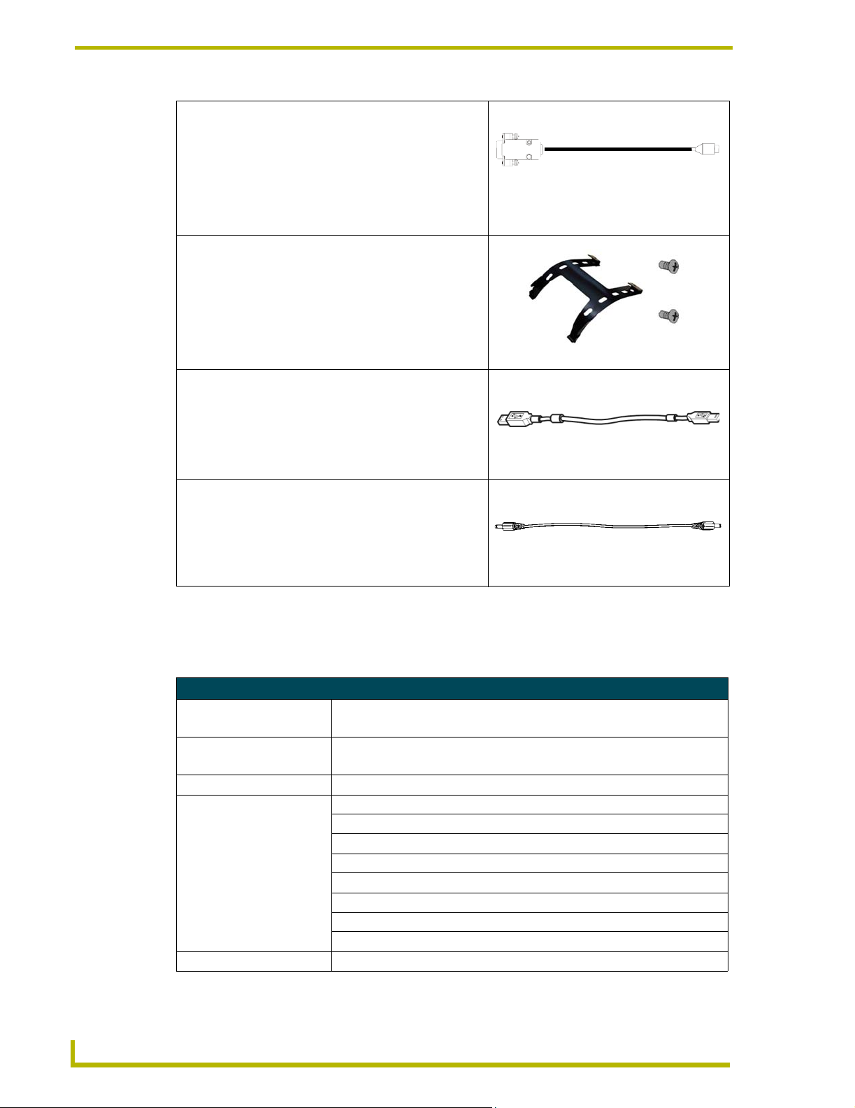
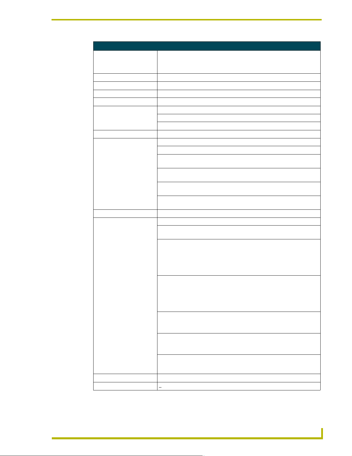
Specifications
Dimensions (HWD):
TableTop Panel • 16.56" x 16.17" x 7.09" (42.08 cm x 41.07 cm x 18.00 cm)
Power Consumption • AC: 90 ~ 265 V, 50 ~ 60 Hz
• < 30 W (On), < 8 W (stand-by), and < 5 W (Off)
On-Screen Properties:
Screens Size 15 inch (38.10 cm) diagonal
Pixel Format 1024 x 768 vertical strip @ 75 Hz
Pixel Pitch 0.297 mm x 0.297 mm
Maximum Pixel Clock 80 MHz
2
Brightness 220 cd/m
Contrast Ratio 300:1
Viewing Angle 160°/160° (minimum)
Color Depth 18-bit (256-color)
Memory EPROM Chip
(typical)
2
PTM-D15 15" Platinum Touch Panel
Page 9
Platinum Touch Panel
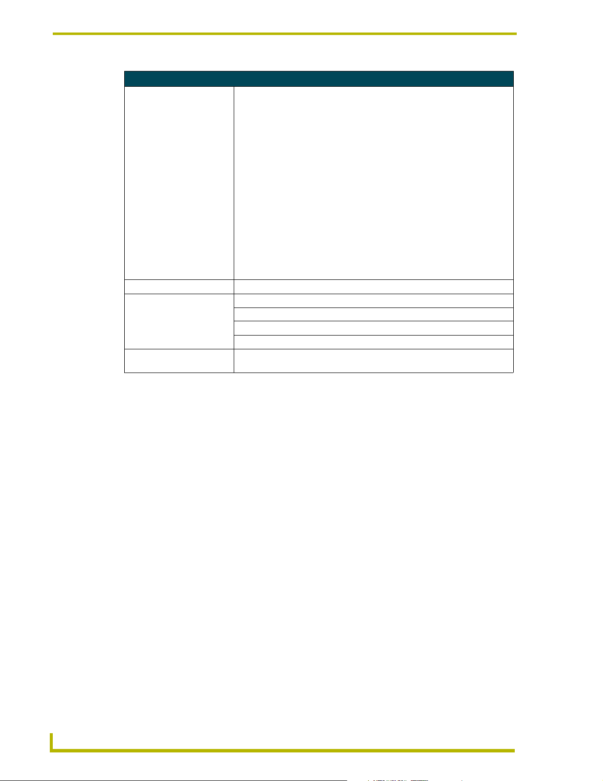
Specifications (Cont.)
Ratings • Safety - UL, CUL, EPA, CB, TUV/BUART, Nordic
• EMI - FCC-B, CE
• VESA - DCC1/2B, DPMS
Enclosure High-impact plastic with gray matte finish
Weight:
PTM-D15 panel 5.5 kg (12.10 lbs.)
Input Signal:
Horizontal Frequency 31 kHz - 60 kHz
Vertical Frequency 50 Hz - 75 Hz
Maximum Pixel Clock 80 MHz
Rear Panel Buttons:
Power Switch Turns the display On and Off
AUTO Button Adjusts the picture position and performance automatically
UP Button Activates the On-Screen Display menu and moves the menu cursor clockwise
to select menu items.
DOWN Button Activates the On-Screen Display menu and moves the menu cursor counter-
clockwise to select menu items.
Increase Button (+) Activates the On-Screen Display menu. Selects the menu items and adjusts
their features (increases values).
Decrease Button (-) Activates the On-Screen Display menu. Selects the menu items and adjusts
Rear Panel Connectors:
VGA Analog Input 15-pin Mini D-Sub (DB-15) connector for input of VGA signals
PWR 12 VDC 3-pin AC plug provides power to the display. Supplied by connecting
USB Upstream Port Type 2 USB connector to Type 1 USB connector plug. Used to provide
USB Downstream Port Type 1 USB connector to Type 1 USB connector plug. Used to communicate
Line In 3.5 mini-jack for audio input connector. Used to feed an external audio source
Line Out 3.5 mini-jack for audio output connector. Used to transmit audio to an external
TouchScreen Signal Cable 8-pin Mini Din to 9-pin (DB-9) connector for TouchScreen signal
Tilt Angle 30° (degrees from vertical)
Base Swivel Angle +
their features (decreases values).
the Power Adapter and Power Cord.
communication between the touch panel and a video source.
• Self-powered; 5V/500Ma (max.)
• Full speed transfer @ 12Mb/sec and Low speed transfer @ 1.5Mb/sec
• USB 1.1 compliant
between USB devices.
• Self-powered; 5V/500Ma (max.)
• Full speed transfer @ 12Mb/sec and Low speed transfer @ 1.5Mb/sec
• USB 1.1 compliant
into the touch panel.
• Frequency response: 80Hz - 20KHz (typical)
audio source.
• Practical output: 1.5w + 1.5w RMS (typical)
communication between the panel and computer/panel interface through
COM1 or COM2.
360° (from center position)
TM-D15 15" Platinum Touch Panel
3
Page 10
Platinum Touch Panel
Specifications (Cont.)
User Presets:
1
2
3
4
5
6
7
8
9
10
11
12
13
14
Environmental:
Operating Temperature 0° C to 40° C (32° F to 104° F)
Storage Temperature -20° to 60° C (-4° F to 140° F)
Operating Accessories 10% to 90%
Storage Humidity 5% to 95%
Accessories Refer to the Platinum Package Components section on page 1 for more
• 640 x 350 31.5 KHz 70 Hz IBM VGA
• 640 x 480 31.5 KHz 60 Hz IBM VGA
• 640 x 480 35.0 KHz 67 Hz Macintosh
• 640 x 480 37.9 KHz 72 Hz VGA/72
• 640 x 480 37.5 KHz 75 Hz VGA/75
• 720 x 400 31.5 KHz 70 Hz IBM VGA
• 800 x 600 35.2 KHz 56 Hz SVGA/56
• 800 x 600 37.9 KHz 60 Hz SVGA/60
• 800 x 600 48.1 KHz 72 Hz SVGA/72
• 800 x 600 46.9 KHz 75 Hz SVGA/75
• 832 x 624 49.7 KHz 75 Hz Macintosh
• 1024 x 768 48.4 KHz 60 Hz XGA/60
• 1024 x 768 56.5 KHz 70 Hz XGA/70
• 1024 x 768 60.0 KHz 75 Hz XGA/75
information
4
PTM-D15 15" Platinum Touch Panel
Page 11
Platinum Touch Panel
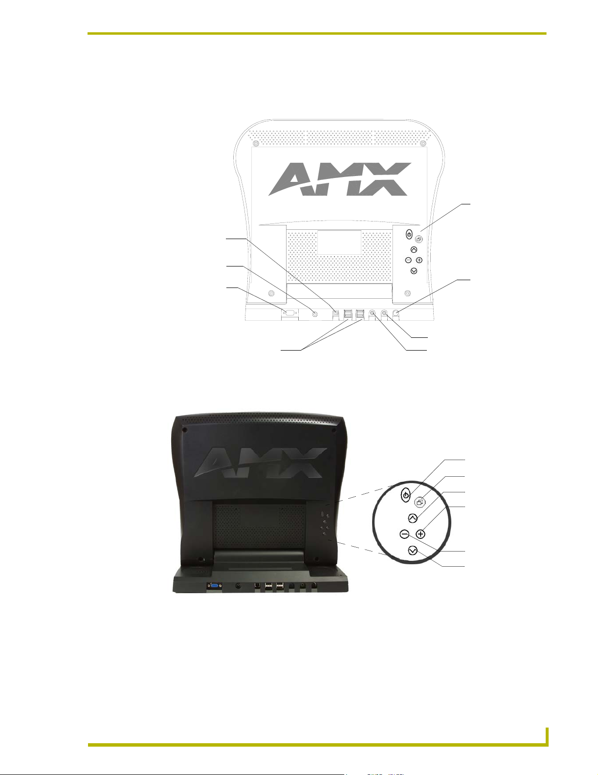
PTM-D15 Rear Components
FIG. 1 shows the rear components of the PTM-D15 15" Platinum Touch Panel.
On-Screen Display
menu buttons
USB Upstream
port
DC Power
connector
VGA In connector
(DB-15)
Line In
Line Out
VGA IN DC INPUT
USB Upstream
USB Downstream
Screen Interface
USB Downstream ports
FIG. 1 Rear component connection locations on the PTM-D15
FIG. 2 shows the On-Screen Display menu buttons on the PTM-D15.
PTM-D15 Platinum
Touch Panel (rear view)
Touch Screen
input cable
(8-pin Mini DIN)
Audio Line Out connector
Audio Line In connector
Power button
Menu Select button
Up button
Increase button
FIG. 2 Rear panel buttons
TM-D15 15" Platinum Touch Panel
Decrease button
Down button
On-Screen Display
Menu buttons
5
Page 12
Platinum Touch Panel
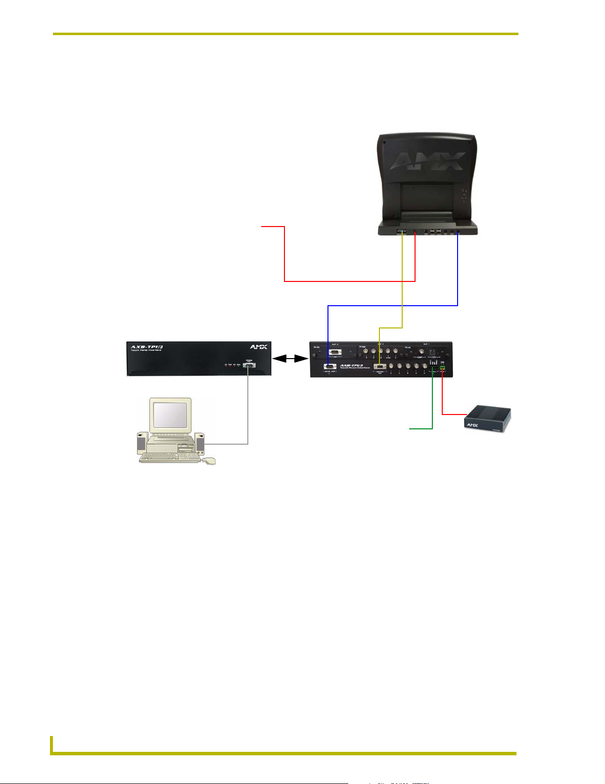
PTM-D15 Sample Configuration
FIG. 3 shows a sample application for the 15" Platinum Table Top Panel using a TPI/3, touch panel,
computer (used to configure the TPI/3), and Central Controller.
PTM-D15
Platinum
To u ch
Panel
External Power
(Adapter and Cord)
DB-9 to 8-pin mini-DIN
15-pin VGA cable
AMX AXB-TPI/3 (front view)
DB-9 connecting
Program Port from
TPI/3 to COM1/2
on rear of computer
Computer
FIG. 3 Sample Platinum Touch Panel Configuration
AMX AXB-TPI/3 (rear view)
(showing optional input cards)
AXlink 4-pin
connection to
Central Controller
2-pin captive-wire
AMX PSN6.5
Power Supply
Power to the PTM-D15 touch panel is supplied through an external power supply. Power to the TPI/
3 can be supplied either directly through a PSN6.5 or indirectly through an AXlink cable
connection from a Central Controller. The power source is dependant on the distance between the
TPI/3 and the Central Controller. If the distance between the too great, a local power source (like
the PSN6.5) must be used. Refer to the AXB-TPI/3 Touch Panel Interface 3 Instruction Manual for
more detailed information about specifications and wiring distances.
6
PTM-D15 15" Platinum Touch Panel
Page 13
Installation and Wiring
This section covers the steps necessary to setup the individual Platinum components and connect
them together. The three areas of focus are the main component setup, installation, wiring, and
connection.
Setting up the Panel
The setup of the Platinum Touch Panel involves unpacking the unit, attaching the particular type of
panel support, and connecting the appropriate cables.
1. Remove the panel from the shipping case.
2. Lay the back of the panel on a flat surface.
3. Fold up/out the base.
4. Remove the dust-proof plastic sheet (FIG. 4) from the screen (if applicable).
Installation and Wiring
FIG. 4 Removing the protective cover
Table Top Installation (PTM-D15)
This process involves installing the support bracket and connecting the appropriate cables to their
respective locations/connectors.
Installing the Table Top support bracket
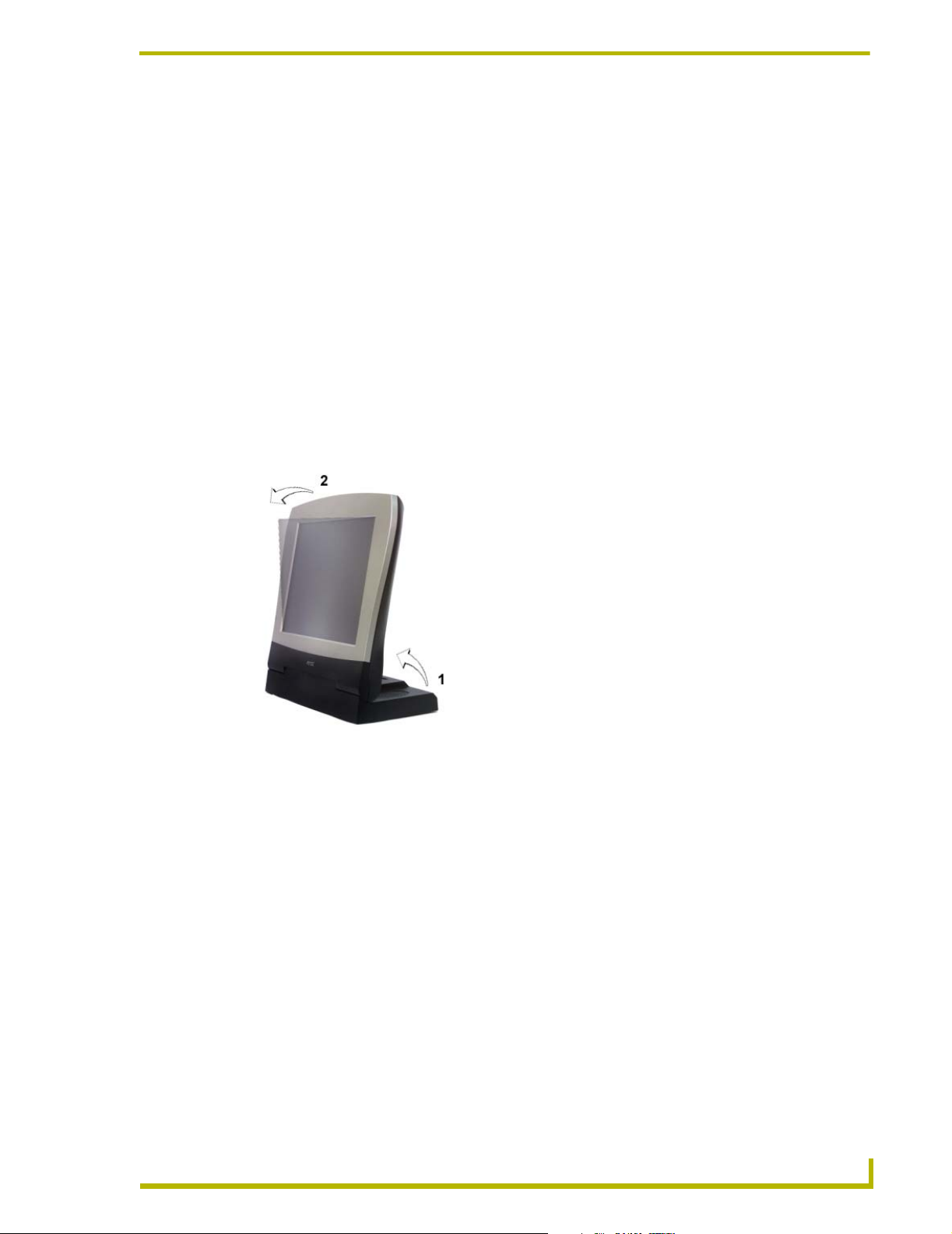
To avoid vibrations when you touch the display, install the Table Top support bracket. After
installation of the bracket, the display tilt angle is approximately 30-degrees from vertical.
1. While on a flat surface, use both hands to gently unfold (pull-down) the display stand by
flipping it downward (FIG. 4).
2. To fix the panel into position, hold the base with one hand and use the other to angle the panel
into position.
3. Insert the double-raised end of the Table Top Support Bracket (FIG. 5) into the fixing grooves
located on the display stand. One support bracket and two screws come with the PTM-D15.
There are two rows of fixing grooves on the stand.
PTM-D15 15" Platinum Touch Panel
7
Page 14

Installation and Wiring
FIG. 5 Fixing grooves on rear of the panel
4. Verify that the folds/latches at the bottom of the bracket are securely located within the fixing
5. Align the screws holes (on the rear of the panel) with the openings at the top of the bracket
Table Top
Support Bracket
Screw Holes
Fixing
Grooves
(2 rows)
grooves.
(FIG. 6).
Screws (2)
Screws holes
Fixing grooves
FIG. 6 Attaching the Table Top Bracket to the rear of the panel
6. Insert the two screws into their respective locations and begin tightening until the screws are
securely fastened into the panel.
7. Verify that the panel is securely connected to the Table Top Bracket at both ends.
8
PTM-D15 15" Platinum Touch Panel
Page 15

Installation and Wiring
Connecting the cables on a PTM-D15 panel
1. Connect the VGA Input, Touch Screen Signal, and Power cables to the PTM-D15 touch panel
as shown in FIG. 7.
VGA Input cable -
connects from panel
to Monitor Out port
on TPI/3
Touch Screen cable connects from panel to
Mouse Port on TPI/3 or
related touch interface
port
USB
12 VDC connector - routes
power from the power cord and
adapter
Power Adapter
FIG. 7 Attaching the cables to the rear of the PTM-D15
Input
Audio
Do not plug in the power cord to the Power Adapter at this time. Power is supplied
after the entire system is wired together. Refer to the Connecting to Optional
Components section on page 10 for powering procedures.
2. Once the installation of the Table Top Bracket and the connection of the appropriate cables are
finished, follow the steps in the Connecting to Optional Components section on page 10.
Using the VGA IN DB-15 (male) high-density connector
Connect the DB-15 (female) video connector to the VGA IN DB-15 (male) high-density connector
on the rear panel of the touch panel. The following table below lists the VGA IN DB-15 connector
pinouts.
PTM-D15 15" Platinum Touch Panel
9
Page 16

Installation and Wiring
VGA IN DB-15 Connector Pinouts
Pin Signal Function
1 Red Red signals
2 Green Green signals
3 Blue Blue signals
4 N/A Not used
5 GND Signal Ground
6 RAGND Red analog ground
7 GAGND Green analog ground
8 BAGND Blue analog ground
9 N/A Not used
10 SAGND Synchronization analog ground
11 N/A Not used
12 N/A Not used
13 HSYNC Horizontal synchronization signal
14 VSYNC Vertical synchronization signal
15 N/A Not used
5
1
VGA DB-15 (male)
connector
10
15
11
6
Connecting to Optional Components
In this example, the Platinum panel is connected to a TPI/3 interface.
1. Connect the VGA signal cable from the rear of the PTM-D15 panel to the Monitor Out port on
the back of the TPI/3 (FIG. 8).
Touch Screen cable - connects to
Mouse Port on TPI/3
Mouse port
Monitor Out
port
VGA Input cable - connects to
Monitor Out port on TPI/3
FIG. 8 Attaching the cables from the panel to the rear of the AXB-TPI/3
Connect
incoming
video to
TP3-VID
card
10
2. Connect the Touch Screen signal cable from the rear of the panel to the Mouse Port on the back
of the TPI/3.
3. Connect the incoming video signal connector to either the Composite or S-Video connector
ports on the TP3-VID card.
PTM-D15 15" Platinum Touch Panel
Page 17

Installation and Wiring
4. Connect a standard RS-232 cable to the Program Port on the front of the TPI/3 Touch Panel
Interface to the COM1 or COM2 ports on the back of your computer.
5. Verify that the PTM-D15 display is switched Off.
6. Provide power by either connecting the 4-pin AXlink cable from the Central Controller to the
AXlink connector port at the rear of the TPI/3 or by using a local PSN6.5 power supply. Use
the local PSN only if the distance from the power source exceeds the wiring lengths for the
TPI/3 as described in the AXB-TPI/3 Touch Panel Interface 3 Instruction Manual. The AXB-
TPI/3 beeps when you apply power and again when AXlink communication is detected.
7. Connect the Power Adapter to the female connector on the Power Cord and then connect the
Power Cord to an electrical outlet (FIG. 9).
FIG. 9 Connection of power cord to power cable
Your system is now connected and receiving power.
PTM-D15 15" Platinum Touch Panel
11
Page 18

Installation and Wiring
12
PTM-D15 15" Platinum Touch Panel
Page 19

Configuration and Setup
This section covers the steps needed to configure the PTM-D15 panel communication features for
communication to a sample TPI/3 Interface using either Axcess or NetLinx.
PTM-D15 Startup and Setup Procedures
Now that the Platinum Touch Panel is powered and connected to the AXB-TPI/3 Touch Panel
Interface, all that’s left to do is to get the display settings adjusted and prepare it for displaying the
incoming signals from the TPI/3.
Rear Panel buttons
On the middle-right side of the touch panel is located a set of buttons that allow the user to activate
the panel and access panel display menus (FIG. 10). Refer to the Specifications section on page 2
for more information on the rear panel buttons.
Configuration and Setup
PTM-D15 Platinum
Touch Panel (rear view)
Power button
Menu Select button
Up button
Increase button
Decrease button
On-Screen Display
Menu buttons
FIG. 10 Rear panel buttons
Down button
1. Press the Power button on the panel to turn on the monitor. If no image appears on your
monitor, refer to the Troubleshooting section on page 33.
2. Adjust the resolution of the video signal from the video source.
For best picture quality when using the panel to display an incoming computer signal,
adjust the video signal resolution from the computer to 1024 x 768 at 60 Hz.
The following sections require that you first use the TPI/3 with a Terminal Emulator (i.e., AxcessX
or Windows HyperTerminal).
PTM-D15 15" Platinum Touch Panel
13
Page 20

Configuration and Setup
Setting Up Serial Communication from PC to the TPI/3
Communication to the TPI/3 is done through a DB-9 (serial) connection from your PCCOM port to
the Program port on the AXB-TPI/3 when the Computer is in close proximity to the TPI/3. When
the TPI/3 is either located too far or inaccessible to a direct PC connection, communication is done
through the Axcess Central Controller.
There are two programs that can be used to establish the communication in an Axcess control
system: AxcessX or HyperTerminal. Both programs use the same sets of commands when talking
either serially or through an Axcess Central Controller.
Setting Up Serial procedures
1. Note that the default refresh rates and resolution options for the panel are 1024 x 768 @ 60 Hz.
2. Follow the procedures for configuring the TPI/3 (in sequence), beginning with the Setting Up
Using AxcessX for serial communication
To set up terminal emulator mode using a single serial connection:
Serial Communication from PC to the TPI/3 section on page 14, Setting up the PTM-D15
touch device section on page 16, and ending with the Calibrating the Monitor section on
page 18 before attempting to use the PTM-D15 with the TPI/3.
1. Verify the connection of one end of a RS-232 (DB-9) cable from the selected COM port on the
back of the PC to the Program Port on the front of the TPI/3.
2. Verify that the AXB-TPI/3 is receiving power through either an external power source or the
AXlink cable connection from the Controller. The AXB-TPI/3 beeps when you apply power
and again when AXlink communication is detected.
3. Verify the connection of the DB-15 video cable from your PTM-D15 panel to the Monitor Out
port at the rear of the TPI/3.
4. Verify the connection of the Touch Screen Signal cable from the touch monitor to the Mouse
Port on the rear of the TPI/3.
5. Launch the AxcessX program from the Start > Programs > AMX Control Disc > AXCESS >
AMX DOS Tools folder. HyperTerminal or other Terminal Emulators can be used. The
following instructions are for use with the Terminal Emulator in Axcess.
6. While in AxcessX, press the F4 key to access the Communications menu.
7. Open the Configuration page by selecting Configure, from the Communication menu. Use this
menu to configure the communication parameters between the computer and the TPI/3. If your
computer is connected properly, communicating correctly, and on the proper COM setting,
PUSH[1,1] appears at the bottom of the main program screen after restarting the program.
The Configure page displays a window of communication options. Defaults are COM 1,
9600-baud (bits per second) data rate, and LPT1.
14
8. Choose a COM port and set its parameters (bits per second and LPT number). The preferred
COM port parameters are listed in the following table.
PTM-D15 15" Platinum Touch Panel
Page 21

Configuration and Setup
COM Port Parameter Settings
Parameter Setting
Bits per second 38,400
Data bits 8 bits
Parity No parity
Stop bits 1
Flow control None
9. Press F10 to save the changes and exit the Configure page.
10. Select Terminal Emulator from the Communications menu to enter the Communications
Terminal window. Since the ESC key is a legal character in the communications mode, use the
F10 key to exit from this menu option.
Terminal Emulator (Ctrl-t) displays a communications window. Highlighting this option and
pressing ENTER places a "TERMINAL" window on the monitor. The menu bar along the top
of the window provides controls for changing the display and communications options.
• <ASC> - Display (ASCII, Hexadecimal, Decimal) • F2-Changes the character bits.
• 8 - Character Bits (5, 6, 7, 8) • F3-Changes the parity.
• N - Parity (E, O, M, S, N) • F4-Changes the number of stop bits.
• 1 - Stop Bits (1 or 2) • F9-Opens the Configure menu.
• F1- Changes the display format. • F10-Returns to the main screen.
11. Type
ECHO ON (will not appear) and press ENTER. Although there are no characters
displayed, the window is now active and ready to receive commands.
The remaining setup instructions must be done after ECHO ON has been entered.
12. Type
HELLO and press ENTER. This message is used to verify that serial communication has
been established. When a valid connection exists, the device responds with
DOING.
HOW ARE YOU
13. Follow the remaining setup procedures for an Axcess system configuration as listed in the
Setting up the PTM-D15 touch device section on page 16. The commands used for AxcessX
and HyperTerminal are the same.
Using HyperTerminal for serial communication
1. Refer to steps 1 through 4 in the Using AxcessX for serial communication section on page 14
before beginning communication.
2. Launch the HyperTerminal program from the Start > Programs > Accessories >
Communications > HyperTerminal folder > Hyperterm.exe.
3. In the Connection Description dialog box, enter a fictitious name into the Name field.
4. In the Connect To dialog box, select the COM port being used for communication to the TPI/3.
PTM-D15 15" Platinum Touch Panel
15
Page 22

Configuration and Setup
5. In the COM Properties dialog box, select the default Bits per Second rate of 38400 and turn
Flow Control to None.
6. Type
ECHO ON (will not appear) and press ENTER. Although there are no characters
displayed, the window is now active and ready to receive commands.
7. Type
HELLO and press ENTER. This message is used to verify that serial communication has
been established. When a valid connection exists, the device responds with
HOW ARE YOU
DOING.
8. Follow the remaining setup procedures for an Axcess system configuration. The commands
used for AxcessX and HyperTerminal are the same.
Setting up the PTM-D15 touch device
The touch drivers are already part of the firmware downloaded from SoftROM but you still have to
use terminal emulator to configure the touch device with the desired driver. Refer to the
Programming section of the AXB-TPI/3 Touch Panel Interface 3 instruction manual for more
information on the MOUSE command.
To configure the touch panel with the correct driver:
1. Verify that all devices are correctly attached (including all cables on the panel and power
sources) to the AXB-TPI/3.
2. Enter
?PAR to verify that the TPI/3 characteristics are correct. The return from the TPI/3
includes these characteristics:
• Version indicates the TPI/3 firmware version on
the TPI/3.
• Mouse Type displays the mouse driver
assigned for use through the TPI/3.
• Device # identifies the beginning device address
for the attached touch device.
• # Devices identifies the number of devices that
are assigned for use through the touch panel
firmware.
• Output Resolution displays the horizontal,
vertical, and refresh rate for the monitor
connected to the TPI/3.
• Cursor enabled displays whether the
cursor is enabled/disabled.
• Brightness displays the brightness value
associated with the monitor. The ability to
adjust the brightness value is not available.
• Contrast displays the contrast value
associated with the monitor. The ability to
adjust the contrast value is not available.
Do not calibrate the TPI/3 if you are using a Microsoft® compatible mouse or a mobile
mouse. Do not enter the <> when entering the values or commands.
3. Use the following command and Device IDs to set the mouse driver:
Mouse<# for touch driver>
This command allows you to see the characters on the display as you type them. The following table lists
the supported touch devices and their associated ID’s.
PRGM EX. 1
16
PTM-D15 15" Platinum Touch Panel
Page 23

Supported Touch Devices
Touch Device ID
No touch device 00
Microsoft serial mouse 01
2nd Microsoft Serial Mouse
(MX-MM Mobile Mouse
®
Dynapro
MicroTouch
Elo IntelliTouch
touch monitors
Elo AccuTouch
EZ Screen
External touch driver FF
touch monitor 10
®
touch monitor 11
®
®
®
touch monitor 15
®
)
and PTM-D15
touch monitor 13
02
12
Mouse 12
This sets the TPI/3 touch device to the PTM-D15 Platinum Touch Panel.
PRGM EX. 2
Configuration and Setup
4. Type
?PAR again to verify the driver. The touch name should say Elo IntelliTouch.
Setting the Output Resolution
The output resolution for the monitor must be configured then calibrated.
Available Resolutions
Resolution Refresh Rates
640 x 480 (VGA) 60 Hz, 72 Hz, 75 Hz, 85 Hz
800 x 600 (SVGA) 56, Hz, 60 Hz, 72 Hz, 75 Hz
1024 x 768 (XGA) (default) 60 Hz
To set the resolution:
1. Verify the connection of the output display monitor to the Monitor Out port at the rear of the
TPI/3.
2. Use the following command in Terminal Emulator mode:
Resolution <hor>x<vert>:<refresh>
Allows you to set the resolution (horizontal/vertical) and refresh rate of the touch panel.
PRGM EX. 3
Refer to the Specifications table on page 2 for the horizontal, vertical, and refresh rates available for
the output coming from the TPI/3.
Resolution 1024x768:60
This sets the TPI/3 to send a video signal at 1024 x 768 with a refresh rate of 60 Hz.
PRGM EX. 4
If the video is blurry, try a different refresh rate and/or resolution. Check the output
device to verify you are using refresh rates and resolution settings are compatible
with the device.
PTM-D15 15" Platinum Touch Panel
17
Page 24

Configuration and Setup
Calibrating the Monitor
Once the monitor is resized, calibrate it to use the touch drivers.
1. In terminal emulator mode, there are 3 commands used for calibration:
2. Calibrate the TPI/3 by entering:
PRGM EX. 5
3. Press the middle of the on-panel cross-hairs as they appear. After the last cross-hair has been
4. Press the screen to exit from the calibration session and return to the panel display.
! Calibrate sets the monitor to begin the calibration test mode.
! Get Cal provides you with the current calibration values.
! Check Cal allows you to manually check the calibration on the monitor by using your
touch on the panel to display an on-screen cross-hair.
calibrate
Sets up the panel to begin the calibration process. Touch the cross-hairs that appear on the panel to complete the calibration process.
depressed and the coordinates points have been set, a dialog displays the panel coordinate
values.
5. Verify and check the calibration of the TPI/3 by entering:
check cal
Verifies that the panel has been correctly calibrated. Touch panel at any location and it should correspond
to the appearance of a cross-hair.
PRGM EX. 6
6. Then begin touching the panel at various locations to reveal an underlying cross-hair. The
touch points and cross-hairs should correspond in their locations.
7. Exit the AxcessX or HyperTerminal programs.
Setting Up AXlink Communication from Master to the TPI/3
When the TPI/3 is either located too far or inaccessible to a direct PC connection, communication is
done through the Axcess Central Controller (Master). Communication through the Axcess Master
is done via the use of Send Commands that are sent to the device using a specific Device ID
number.
There are two programs that can be used to establish the communication in an Axcess control
system: AxcessX or HyperTerminal. Both programs use the same sets of commands when talking
either serially or through an Axcess Central Controller.
Setting Up AXlink procedures
1. Note that the refresh rates and resolution options for the panel are 1024 x 768 @ 60 Hz.
18
2. Follow the procedures for configuring the TPI/3 (in sequence), beginning with theSetting Up
AXlink Communication from Master to the TPI/3 section on page 18, and Setting up the PTM-
D15 touch device through AXlink section on page 19 before attempting to use the
PTM-D15 with the TPI/3.
PTM-D15 15" Platinum Touch Panel
Page 25

Configuration and Setup
Using AXCESSX for AXlink communication
1. Verify the connection of one end of a AXlink cable on the rear of the TPI/3 to the respective
connector location on the Axcess Central Controller.
2. Verify that the AXB-TPI/3 is receiving power through either an external power source or the
AXlink cable connection from the Controller. The AXB-TPI/3 beeps when you apply power
and again when AXlink communication is detected.
3. Verify the connection of the DB-15 video cable from your PTM-D15 panel to the Monitor Out
port at the rear of the TPI/3.
4. Verify the connection of the Touch Screen Signal cable from the touch monitor to the Mouse
Port on the rear of the TPI/3.
5. Refer to the Using AxcessX for serial communication section on page 14 for the steps needed
to open and prepare the program for communication.
Using HyperTerminal for AXlink communication
1. Verify the connection of one end of a AXlink cable on the rear of the TPI/3 to the respective
connector location on the Axcess Central Controller.
2. Verify that the AXB-TPI/3 is receiving power through either an external power source or the
AXlink cable connection from the Controller. The AXB-TPI/3 beeps when you apply power
and again when AXlink communication is detected.
3. Verify the connection of the DB-15 video cable from your PTM-D15 panel to the Monitor Out
port at the rear of the TPI/3.
4. Verify the connection of the Touch Screen Signal cable from the touch monitor to the Mouse
Port on the rear of the TPI/3.
5. Refer to the Using HyperTerminal for serial communication section on page 15 for the steps
needed to open and prepare the program for communication.
Setting up the PTM-D15 touch device through AXlink
The touch drivers are already part of the firmware downloaded from SoftROM but you still have to
use terminal emulator to configure the touch device with the desired driver. Refer to the
Programming section of the AXB-TPI/3 Touch Panel Interface 3 instruction manual for more
information on the @MOU command.
To configure the touch panel with the correct driver:
1. Verify that all devices are correctly attached (including all cables on the panel and power
sources) to the AXB-TPI/3.
2. Type
ECHO ON (will not appear) and press ENTER. Although there are no characters
displayed, the window is now active and ready to receive commands.
3. Type
4. Type
SHOW INPUT ON and press ENTER.
VER and press ENTER to get the Device ID number for the TPI/3 Touch Panel Interface.
Do not calibrate the TPI/3 if you are using a Microsoft® compatible mouse or a mobile
mouse. Do not enter the <> when entering the values or commands.
PTM-D15 15" Platinum Touch Panel
19
Page 26

Configuration and Setup
5. Use the following command to set the mouse driver:
PRGM EX. 7
6. Set the Output resolution of the TPI/3 by entering:
PRGM EX. 8
7. Refer to the Available Resolutions table on page 17 for information on resolution and refresh
8. Calibrate the TPI/3 by entering:
Send_Command, <TPI/3 device number>,"’@MOU <# for touch driver>’"
Example:
Send_Command 130,"’@MOU 12’"
This command allows you to set the mouse driver number (#12 for PTM-D15) on the TPI/3 device using a
specific Device ID number (#130). The Supported Touch Devices table on page 17 lists the supported
touch devices and their associated ID’s. When
Send_Command, <TPI/3 device number>,"’@res <hor>x<ver>:<res>’"
Example:
Send_Command 130,"’@res 1024x768’"
Sets up the panel to display an output resolution of 1024 x 768 at a default screen refresh rate of 60. If
another refresh rate is needed, enter a colon after the vertical value and then enter the refresh rate value.
rates.
Send_Command, <TPI/3 device number>,“’calibrate’”
Example:
Send_Command 130,"’calibrate’"
Sets up the panel to begin the calibration process. Touch the cross-hairs that appear on the panel to
complete the calibration process.
PRGM EX. 9
9. Once in the calibration mode, press the middle of the on-panel cross-hairs as they appear. After
the last cross-hair has been depressed and the coordinates points have been set, a dialog
displays the panel coordinate values.
10. Press the screen to exit from the calibration session and return to the panel display.
11. Exit the AxcessX or HyperTerminal programs.
Setting Up NetLinx Communication from PC to the TPI/3
Communication to the TPI/3 is done through an ethernet connection from a NetLinx Central
Controller (on a network) to the Program port on the AXB-TPI/3. The main program used in this
method is NetLinx Studio.
Using NetLinx Studio for communication via an Ethernet connection
1. Verify the connection of the network Ethernet cable to the rear of the NetLinx Central
Controller (Master) such as the NXC-ME260.
20
2. Verify that the AXB-TPI/3 is receiving power through either an external power source or the
AXlink cable connection from the Controller. The AXB-TPI/3 beeps when you apply power
and again when AXlink communication is detected.
3. Verify the connection of the DB-15 video cable from your PTM-D15 panel to the Monitor Out
port at the rear of the TPI/3.
PTM-D15 15" Platinum Touch Panel
Page 27

Configuration and Setup
4. Verify the connection of the Touch Screen Signal cable from the touch monitor to the Mouse
Port on the rear of the TPI/3.
5. Launch the NetLinx Studio program from the Start > Programs > AMX Control Disc >
NetLinx > NetLinx Studio folder.
6. From the Main menu bar, select Tools > Master Comm. Settings to display the Communication
Setting dialog box.
7. Select NetLinx from the Platform section.
8. Select Network from the COM Port drop-down menu.
9. Specify the IP Address and IP Port (default is 1319 for a Master Port).
10. Click OK to accept the changes and exit from the Communication Setting dialog box.
11. Select Tools > Windows Telnet from the Main menu bar to open a telnet session.
12. Select Connect > Remote Systems and specify the same IP Address as in step 8.
13. From within the telnet session window, type
SHOW DEVICES. This gives you the device
number of the TPI/3. Example would be a TPI/3 with a value of 00130.
14. Use the following command to set the mouse driver:
Send_Command, <TPI/3 device number>,"’@MOU <# for touch driver>’"
Example:
Send_Command 130,"’@MOU 12’"
This command allows you to set the mouse driver number (#12 for PTM-D15) on the TPI/3 device using a
specific Device ID number (#130). The Supported Touch Devices table on page 17 lists the supported
touch devices and their associated ID’s. When
PRGM EX. 10
15. Set the Output resolution of the TPI/3 by entering:
Send_Command, <TPI/3 device number>,"’@res <hor>x<ver>:<res>’"
Example:
Send_Command 130,"’@res 1024x768’"
Sets up the panel to display an output resolution of 1024 x 768 at a default screen refresh rate of 60. If
another refresh rate is needed, enter a colon after the vertical value and then enter the refresh rate value.
PRGM EX. 11
16. Refer to the Available Resolutions table on page 17 for information on resolution and refresh
rates.
17. Calibrate the TPI/3 by entering:
Send_Command, <TPI/3 device number>,"’calibrate’"
Example:
Send_Command 130,"’calibrate’"
Sets up the panel to begin the calibration process. Touch the cross-hairs that appear on the panel to
complete the calibration process.
PRGM EX. 12
18. Once in the calibration mode, press the middle of the on-panel cross-hairs as they appear. After
the last cross-hair has been depressed and the coordinates points have been set, a dialog
displays the panel coordinate values.
PTM-D15 15" Platinum Touch Panel
21
Page 28

Configuration and Setup
19. Press the screen to exit from the calibration session and return to the panel display.
20. Select Connect > Disconnect to exit from telnet session and close the NetLinx Studio Program.
Using NetLinx Studio for communication via an COM Port
If the NXC-ME260 is not connected to a network via an Ethernet port, communication can then
only be established through the use of a COM Port.
1. Connect one end of an RS-232 (DB-9) cable from the selected Program Port on the from of the
2. Launch the NetLinx Studio program from the Start > Programs > AMX Control Disc >
3. From the Main menu bar, select Tools > Master Comm. Settings to display the Communication
4. Select NetLinx from the Platform section.
5. Select the PC COM Port (from the COM Port drop-down menu) that is being used to
NetLinx Master to the Program Port on the front of the TPI/3. Refer to the individual NetLinx
Master instruction manual for more detailed setup and configuration information. In this
section, an NXC-ME260 will be used for example purposes.
NetLinx > NetLinx Studio folder.
Setting dialog box.
communicate to the NXC-ME260.
6. Click Configure and select the baud rate that the master is using. The default is 38.4.
7. Set the Flow Control to NONE and click OK to accept the changes and exit the
Communication Setting dialog box.
8. Select Tools > Terminal from the Main menu bar.
9. Press ENTER four times to establish communication with the Master Controller and the
terminal.
10. Use the following command to set the mouse driver:
Send_Command, <TPI/3 device number>,"’@MOU <# for touch driver>’"
Example:
Send_Command 130,"’@MOU 12’"
This command allows you to set the mouse driver number (#12 for PTM-D15) on the TPI/3 device using a
specific Device ID number (#130). The Supported Touch Devices table on page 17 lists the supported
touch devices and their associated ID’s. When
PRGM EX. 13
11. Set the Output resolution of the TPI/3 by entering:
Send_Command, <TPI/3 device number>,"’@res <hor>x<ver>:<res>’"
Example:
Send_Command 130,"’@res 1024x768’"
Sets up the panel to display an output resolution of 1024 x 768 at a default screen refresh rate of 60. If
another refresh rate is needed, enter a colon after the vertical value and then enter the refresh rate value.
PRGM EX. 14
22
12. Refer to the Available Resolutions table on page 17 for information on resolution and refresh
rates.
13. Calibrate the TPI/3 by entering:
PTM-D15 15" Platinum Touch Panel
Page 29

Configuration and Setup
Send_Command, <TPI/3 device number>,"’calibrate’"
Example:
Send_Command 130,"’calibrate’"
Sets up the panel to begin the calibration process. Touch the cross-hairs that appear on the panel to
complete the calibration process.
PRGM EX. 15
14. Once in the calibration mode, press the middle of the on-panel cross-hairs as they appear. After
the last cross-hair has been depressed and the coordinates points have been set, a dialog
displays the panel coordinate values.
15. Press the screen to exit from the calibration session and return to the panel display.
16. Select Connect > Disconnect to exit from telnet session and close the NetLinx Studio Program.
PTM-D15 15" Platinum Touch Panel
23
Page 30

Configuration and Setup
24
PTM-D15 15" Platinum Touch Panel
Page 31

On Screen Display (OSD) Features
On Screen Display (OSD) Features
The following sections describe how to adjust display features on the PTM-D15 after the panel is
powered up and connected to the TPI/3 or to another source such as DVD or VCR player.
Press the Menu button ( ) to activate the OSD menu. The following OSD icons represent the
functions within the OSD menu:
On Screen Display (OSD) Icons.
On Screen Display (OSD) Icons
Save & Exit
Automatic Optimization
Next page
Language
Volume (not available on PTM-D15)
Contrast
Clock (display performance)
Phase (display performance)
Horizontal position
Vertical position
Hue; User Color-Display Color
OSD timer
OSD position
Sharpness
Auto contrast
DOS graphic/text
Recall
Color
VGA-In (not available on PTM-D15)
Video-In (not available on PTM-D15)
Video source (not available on PTM-D15)
PTM-D15 15" Platinum Touch Panel
25
Page 32

On Screen Display (OSD) Features
Exiting the OSD
When you are ready to quit the On Screen Display (OSD), press the UP or DOWN buttons to select
Save and Exit ( ) , then press the INCREASE or DECREASE button to save your changes
and exit the OSD.
FIG. 11 Exiting the OSD by Saving and Exiting
You can also press the ( ) button to exit the OSD menu. Exiting the OSD using the
Main menu button does not necessarily save your changes to the panel.
Auto Tuning the Panel
1. Press the Menu button ( ) to activate the OSD menu.
2. Select the Auto Tune icon ( ) and press the INCREASE or DECREASE buttons to
automatically tune the panel to its optimum settings based on the currently saved panel
preferences. This can take a few seconds.
Selecting the Language of the OSD
English, French, German, Spanish, and Italian versions of the OSD menus are available.
1. Press the Menu button ( ) to activate the OSD menu.
2. Press the DOWN button to highlight the Next Page icon ( ), then press the DECREASE
button. The second menu page appears.
3. Press the DOWN button to highlight the Next Page icon ( ), then press the DECREASE
button. The third menu appears.
FIG. 12 Selecting the Language of the OSD
4. The Language icon ( ) is already selected. Press INCREASE or DECREASE to cycle
through the language options.
26
5. Exit the OSD (by using the Save/Exit Icon ( )when the language you prefer is displayed.
Adjusting Audio Volume
1. Press the Menu button ( ) to activate the OSD menu.
2. Press the UP or DOWN button to highlight the Volume icon ( ), then press INCREASE or
DECREASE to adjust the volume level.
PTM-D15 15" Platinum Touch Panel
Page 33

On Screen Display (OSD) Features
Volume can also be adjusted by pressing the UP and
DOWN buttons when outside the OSD menu.
FIG. 13 Adjusting Volume Level
3. Exit the OSD by using the Save/Exit Icon ( ).
Adjusting Screen Brightness and Contrast
1. Press the Menu button ( ) to activate the OSD menu and change the Contrast.
2. Press the UP or DOWN button to highlight the Contrast icon ( ), then press INCREASE or
DECREASE to adjust the Contrast level.
FIG. 14 Adjusting Screen Brightness and Contrast
3. Exit the OSD by using the Save/Exit Icon ( ).
Adjusting Display Performance (Clock and Phase)
Phase and Clock settings allow you to compensate for drift of computer signals. You can press the
Menu button ( ) to optimize both settings. If you want to fine-tune the settings for a specific
application, follow the steps below.
1. Press the Menu button ( ) to activate the OSD menu.
2. Press the UP or DOWN button to highlight the Clock icon ( ), then press INCREASE or
DECREASE to adjust the clock/picture performance.
Increasing the value "stretches" the image to the right
Decreasing the value "contracts" the image toward the left/center
FIG. 15 Adjusting the Clock setting
3. Press the UP or DOWN button to highlight the Phase icon ( ), then press INCREASE or
DECREASE to adjust the phase (as seen on the following page).
4. Exit the OSD by using the Save/Exit Icon ( ).
PTM-D15 15" Platinum Touch Panel
27
Page 34

On Screen Display (OSD) Features
FIG. 16 Adjusting the Phase setting
Adjusting Horizontal and Vertical Screen Position
Horizontal (H Position) and vertical (V Position) settings allow you to adjust the position of the
picture. You can press the ( ) icon to optimize both the settings automatically. To customize the
settings, follow the steps below.
1. Press the Menu button ( ) to activate the OSD menu.
2. Press the UP or DOWN button to highlight the Horizontal Position icon ( ), then press
INCREASE or DECREASE to center the picture horizontally.
FIG. 17 Adjusting the Horizontal Screen Position
3. Press the UP or DOWN button to highlight the Vertical Position icon ( ), then press
INCREASE or DECREASE to center the picture vertically.
FIG. 18 Adjusting the Vertical Screen Position
4. Exit the OSD by using the Save/Exit Icon ( ).
Selecting the Picture Color Temperature
You can change the picture color temperature of your display. Three preset color temperature
modes are available.
! 9300K: recommended for general use
! 6500K: recommended for color management
! 5500K: recommended for photo retouch
1. Press the Menu button ( ) to activate the OSD menu.
28
2. Press the DOWN button to highlight the Next Page icon ( ), then press the DECREASE
button. The Color Adjust page appears.
3. Press the UP or DOWN buttons to highlight 93 (9300K color), 65 (6500K color), or 55 (5500K
color), and press INCREASE or DECREASE to confirm your selection.
PTM-D15 15" Platinum Touch Panel
Page 35

On Screen Display (OSD) Features
FIG. 19 Selecting the Picture Color Temperature
4. Exit the OSD by using the Save/Exit Icon ( ).
Adjusting Display Color (Red, Green, Blue)
The Red, Green, and Blue color settings allow you to fine tune the picture color.
1. Press the Menu button ( ) to activate the OSD menu.
2. Press the DOWN button to highlight the Next Page icon ( ), then press the DECREASE
button. The Color Adjust menu appears.
FIG. 20 Color Adjust menu
3. Press the UP button to highlight the Color icon ( ), and press INCREASE or DECREASE
to confirm your selection. The Red, Blue, and Green Color slide bars appear in the center of
the menu.
4. Press the UP or DOWN buttons to highlight the Red, Blue or Green color bar and press
INCREASE or DECREASE to adjust the color balance up or down.
FIG. 21 Sample selecting the Picture Color Temperature
5. Exit the OSD by using the Save/Exit Icon ( ).
Adjusting OSD Menu Parameters (OSD Position and Timer)
OSD Menu Parameters allow you to change the OSD menu position and the delay time before the
OSD menu disappears.
1. Press the Menu button ( ) to activate the OSD menu.
2. Press the DOWN button to highlight the Next Page icon ( ), then press the DECREASE
button. The second menu appears.
3. Press the UP button to highlight the Next Page icon ( ), then press the DECREASE button.
The third menu appears.
PTM-D15 15" Platinum Touch Panel
29
Page 36

On Screen Display (OSD) Features
4. Press the UP button to highlight the OSD Timer icon ( ), then press INCREASE or
DECREASE to highlight your choice of 10, 15, 20, 25, or 30 seconds.
FIG. 22 Adjusting the OSD Timer setting
5. Press the UP button to highlight the OSD Position icon ( ), then press INCREASE or
DECREASE to adjust the OSD menu position to your selection.
FIG. 23 Adjusting the OSD Position setting
This is the amount of time that OSD menu remains on-screen
after its last use. Also referred to as the "inactivity time".
The OSD positions are chosen from a series of 9 preset
on-screen positions.
6. Exit the OSD by using the Save/Exit Icon ( ).
Adjusting the Picture Sharpness
You may need to adjust Sharpness to optimize the picture performance for your specific
application:
! Purely graphic application: recommend maximum sharpness recommended.
! Purely text application: recommend minimum sharpness recommended.
1. Press the Menu button ( ) to activate the OSD menu.
2. Press the DOWN button to highlight the Next Page icon ( ), then press the DECREASE
button. The second menu appears.
3. Press the DOWN button to highlight the Next Page icon ( ), then press the DECREASE
button. The third menu appears.
4. Press the UP or DOWN button to highlight the Sharpness icon ( ), then press INCREASE
or DECREASE to adjust .
30
FIG. 24 Adjusting the Picture Sharpness
5. Exit the OSD by using the Save/Exit Icon ( ).
PTM-D15 15" Platinum Touch Panel
Page 37

On Screen Display (OSD) Features
Automatic Contrast Adjustment (Auto Contrast)
It is recommended that the automatic contrast process be run every time the monitor resolution or
refresh rate is changed.
1. Press the Menu button ( ) to activate the OSD menu.
2. Press the DOWN button to highlight the Next Page icon ( ), then press the DECREASE
button. The second menu appears.
3. Press the DOWN button to highlight the Next Page icon ( ), then press the DECREASE
button. The third menu appears.
4. Press the UP or DOWN button to highlight the Auto Contrast icon ( ), then press
INCREASE or DECREASE. The display may blink off briefly. It takes approximately 5
seconds for the automatic adjustment process to complete.
FIG. 25 Automatic Contrast Adjustment
5. Exit the OSD by using the Save/Exit Icon ( ).
Optimizing Picture Performance in DOS (Graphic/Text)
In order to optimize the picture performance of your display when using a DOS application, you
may need to select the appropriate DOS mode (graphic or text).
To access DOS in the graphic mode, your computer must include correct DOS drivers
for its video card (not for this monitor). Most applications do not use graphic mode,
because Windows provides the graphic interface.
1. Press the Menu button ( ) to activate the OSD menu.
2. Press the DOWN button to highlight the Next Page icon ( ), then press INCREASE or
DECREASE. The second menu appears.
3. Press the UP or DOWN button to highlight the DOS Text icon ( ). The only available
option on this model is TEXT.
FIG. 26 Selecting the appropriate DOS mode (Text)
4. Exit the OSD by using the Save/Exit Icon ( ).
PTM-D15 15" Platinum Touch Panel
31
Page 38

On Screen Display (OSD) Features
Returning (RECALL) to Factory Default Settings
Use the Recall feature to return all display feature to the factory default settings.
1. Press the Menu button ( ) to activate the OSD menu.
2. Press the DOWN button to highlight the Next Page icon ( ), then press the DECREASE
button. The second menu appears.
3. Press the DOWN button to highlight the Next Page icon ( ), then press the DECREASE
button. The third menu appears.
4. Press the UP or DOWN button to highlight the Recall icon ( ), then press INCREASE or
DECREASE to activate it. Your screen may go blank momentarily during the recall process.
FIG. 27 Automatic Contrast Adjustment
5. Exit the OSD.
Exiting/Saving the OSD
When you are ready to quit the On Screen Display (OSD), press the UP or DOWN buttons to select
Save and Exit, then press the or INCREASE or DECREASE button to save your changes and exit
the OSD menu.
FIG. 28 Exiting the OSD
32
PTM-D15 15" Platinum Touch Panel
Page 39

Troubleshooting
Display Troubleshooting
Match the symptom below that best describes your problem.
Troubleshooting
CAN’T DISPLAY THIS INPUT SIGNAL The input signal is not acceptable by the monitor.
NO PICTURE • Check that the power switch of your computer or video source is
NO SIGNAL INPUT No signal inputs are detected from either the VGA-In or Video-In
NO VIDEO SIGNAL FROM VGA-IN No signal input detected from VGA-In connector.
SCREEN IMAGE IS NOT CENTERED
PROPERLY OR THE EDGES OF THE
DISPLAY ARE NOT VISIBLE
TEXT IS NOT SOLID • Change the resolution of the video signal to 1024 x 768.
Troubleshooting
• Verify the video resolution and frequency range (must be within
the range specified for the monitor).
• Try setting your video adapter to a lower resolution and refresh
rate.
Ex: Set the output resolution on the video source to
800x600@60 Hz and then cycle power.
If this doesn’t work, go to 640x480@31.5 Hz and then cycle up
from there. Once a signal is detected, begin cycling up to a
higher and higher resolution until the maximum resolution is
obtained (1024x768@60Hz).
• DO NOT USE the Optimal or Adapter Default refresh rates
for your adapter.
• For more information on resolution settings, refer to the
Specifications section on page 2.
in the “ON” position.
• Verify the power cord is properly connected to the monitor and to
the power outlet.
• Verify there is power being delivered from the power outlet. (Use
another device to test power).
• Ensure the computer is not in power saving mode. (Move the
mouse or press a key on the keyboard to wake up the
computer.)
• Verify that the video signal cable is properly connected.
connector.
• Verify the video source is "ON".
• Verify the video signal cable is properly connected.
• Verify no pins are damaged on the Video Input connector.
• Verify the video source is "ON".
• Verify the VGA cable is properly connected to the VGA-IN
connecor.
• Verify no pins are damaged on the Video Input connector.
• Press the ( ) button to run the automatic adjustment.
• Adjust the Horizontal and Vertical Positions to fine tune the
image.
• Press the the ( ) button on the front of the panel to run the
auto display adjustment feature.
• Adjust the Clock and Phase in the OSD menu to fine tune.
• Adjust Sharpness in the OSD menu.
PTM-D15 15" Platinum Touch Panel
33
Page 40

Troubleshooting
Troubleshooting (Cont.)
THE USB HUB DOES NOT WORK • Verify the USB cable is properly connected to both the USB port
on the video source and on the monitor base.
• Verify the USB drivers for the video source are properly loaded
and configured.
WAIT FOR AUTOMATIC ADJUSTMENT • The monitor is processing the automatically displayed
adjustment.
• The automatic adjustment process takes about 5 seconds to
complete.
• It is recommended to run auto adjustment by pressing the ( )
button every time the resolution or refresh rate is changed.
Warning Messages and their Meanings
Use these messages to address panel issues.
Warnings and Messages
Cannot Display this Input Signal Check that the video resolution and frequency range are within
that specified for the display. Refer to the Specifications section on
page 2 for more details.
No Signal Input No signal inputs are detected from either the VGA-In or Video-In
connectors.
• Check that the power switch of your computer or video source is
in the “ON” position.
• Check that the video signal cable is properly connected.
• Ensure that no pins are bent in on the video input connector.
Main Control Menu Locked The main control menu (On Screen Display menu) is locked to
avoid unwanted adjustment.
• Press the AUTO button on the front of the panel for 15 seconds
to unlock the main control menu.
No Video Signal from VGA-In No signal input is detected from the VGA-In connector.
• Check that the power switch of your computer is in the “ON”
position.
• Check that the VGA cable is properly connected to the VGA-IN
connector.
• Ensure that no pins are bent in on the video input connector.
Wait for Automatic Adjustment The display is detecting the input signal and then automatically
adjusting the display parameters accordingly.
• It takes around 5 seconds to finish the whole process.
• Run the auto adjustment by pressing every time you change the
resolution or refresh rate.
Use 1024 x 768 for best performance The current resolution of the video signal is not 1024 x 768.
The performance of this display is optimized for a resolution of
1024 x 768.
Set the incoming signal to those parameters.
34
PTM-D15 15" Platinum Touch Panel
Page 41

Troubleshooting
PTM-D15 15" Platinum Touch Panel
35
Page 42

AMX reserves the right to alter specifications without notice at any time.
DALLAS, TEXAS • LOS ANGELES, CALIFORNIA • MEXICO CITY, MEXICO • ONTARIO, CANADA • PHILADELPHIA, PENNSYLVANIA • SHANGHAI, CHINA • SINGAPORE • TAMPA, FLORIDA • WESTERLO, BELGIUM • YORK, ENGLAND
3000 RESEARCH DRIVE, RICHARDSON, TX 75082 USA • 800.222.0193 • 469.624.8000 • 469-624-7153 fax • 800.932.6993 technical support • www.amx.com
2002 AMX Corporation. All rights reserved. AMX, the AMX logo, the building icon, th e home icon, and the light bulb icon are all trademarks of AMX Corporation.
©
036-004-2628 9/02
AMX reserves the right to alter specifications without notice at any time. *In Canada doing business as Panja Inc.
 Loading...