

Page 1
AMX Lighting
PROlink/AXlink Programming
instruction manual
Lighting Control
Page 2

AMX Limited Warranty and Disclaimer
AMX Corporation warrants its products to be free of defects in material and workmanship under normal use for
three (3) years from the date of purchase from AMX Corporation, with the following exceptions:
• Electroluminescent and LCD Control Panels are warranted for three (3) years, except for the display and touch
overlay components that are warranted for a period of one (1) year.
• Disk drive mechanisms, pan/tilt heads, power supplies, MX Series products, and KC Series products are
warranted for a period of one (1) year.
• Unless otherwise specified, OEM and custom products are warranted for a period of one (1) year.
• Software is warranted for a period of ninety (90) days.
• Batteries and incandescent lamps are not covered under the warranty.
This warranty extends only to products purchased directly from AMX Corporation or an Authorized AMX Dealer.
AMX Corporation is not liable for any damages caused by its products or for the failure of its products to perform.
This includes any lost profits, lost savings, incidental damages, or consequential damages. AMX Corporation is not
liable for any claim made by a third party or by an AMX Dealer for a third party.
This limitation of liability applies whether damages are sought, or a claim is made, under this warranty or as a tort
claim (including negligence and strict product liability), a contract claim, or any other claim. This limitation of
liability cannot be waived or amended by any person. This limitation of liability will be effective even if AMX
Corporation or an authorized representative of AMX Corporation has been advised of the possibility of any such
damages. This limitation of liability, however, will not apply to claims for personal injury.
Some states do not allow a limitation of how long an implied warranty last. Some states do not allow the limitation or
exclusion of incidental or consequential damages for consumer products. In such states, the limitation or exclusion of
the Limited Warranty may not apply. This Limited Warranty gives the owner specific legal rights. The owner may
also have other rights that vary from state to state. The owner is advised to consult applicable state laws for full
determination of rights.
EXCEPT AS EXPRESSLY SET FORTH IN THIS WARRANTY, AMX CORPORATION MAKES NO
OTHER WARRANTIES, EXPRESSED OR IMPLIED, INCLUDING ANY IMPLIED WARRANTIES OF
MERCHANTABILITY OR FITNESS FOR A PARTICULAR PURPOSE. AMX CORPORATION
EXPRESSLY DISCLAIMS ALL WARRANTIES NOT STATED IN THIS LIMITED WARRANTY. ANY
IMPLIED WARRANTIES THAT MAY BE IMPOSED BY LAW ARE LIMITED TO THE TERMS OF THIS
LIMITED WARRANTY.
Page 3

Lighting Sales Information
AMX Lighting products are guaranteed to switch on and off any load that is properly connected to our lighting products, as long as the AMX Lighting products are under warranty. AMX Corporation does guarantee the control of dimmable loads that are properly connected to our lighting products. That includes loads correctly chosen, sized and
attached to our dimmers or switches under normal power conditions. Any load that cannot be verified by its manufacturer as rated for dimming is not guaranteed by AMX Corporation to dim properly. This includes various lamps, ballasts and transformers, as well as items no longer covered by warranty.
The dimming of low-voltage lighting requires the use of a dimmable transformer. Transformer manufacturers must
verify that the transformer is dimmable according to written or known specifications. Although AMX Corporation
will try to discern the dimming capability of a transformer by any manufacturer, it is still the responsibility of the
dealer to obtain this information. Therefore, an AMX Corporation dimmer designed for forward-phase dimming
should not be connected to a transformer that requires a reverse-phase dimmer.
The dimming of fluorescent lighting requires the use of a dimmable ballast and a dimmable lamp. Ballast manufactures must verify that the ballast is dimmable according to written or known specifications. Although AMX Corporation will try to discern the dimming capability of a ballast from the manufacturer, it is still the responsibility of the
dealer to obtain this information. Each dimmable ballast must be connected to the proper AMX Corporation Lighting
dimmer and a lamp specified for dimmable operation. We guarantee fluorescent dimming capability when the proper
AMX Fluorescent dimmer module is connected to the proper dimming ballast and a verified dimmable lamp.
Lamps must be verified as dimmable to ensure proper dimming. Lamps with integrated ballasts and transformers, as
well as other passive or electronic devices attached to the lamps must have written verification from the manufacturer
of dimming capability. Fluorescent lamps used for dimming should be operated in a full on condition for approximately four days before the dimming performance stabilizes.
The dimming performance or quality cannot be guaranteed due to the random combinations of a dimmer, a lamp and
a ballast or transformer. How well a device dims depends on many factors that cannot be controlled by AMX Lighting. AMX dimmers regulate the voltage to a lamp, ballast or transformer. AMX Corporation does not regulate lumen
output performance for a device manufactured by another company.
Page 4

Page 5

Table of Contents
Table of Contents
Introduction ...............................................................................................................1
PROlink ............................................................................................................................. 1
PROlink wall panels ................................................................................................................. 2
Lighting Systems ............................................................................................................... 2
Axcess Statements............................................................................................................ 3
Programming Commands ................................................................................................. 4
Setup commands ..................................................................................................................... 4
Recording commands .............................................................................................................. 4
Status commands .................................................................................................................... 4
Operation commands............................................................................................................... 4
Control Curves .................................................................................................................. 4
Pre-Installation Settings ..........................................................................................7
Dry Closures...................................................................................................................... 7
Configuring and connecting AXlink .......................................................................................... 7
Configuring and connecting PROlink ....................................................................................... 8
Connecting dry closures........................................................................................................... 9
Dry closure method to reset Default Settings.................................................................... 9
Default Settings and Parameters .................................................................................... 10
Wiring Considerations ..................................................................................................... 12
Preparing/connecting captive wires ....................................................................................... 12
Axcess Control - PC to Axcess Controller.............................................................................. 12
AXlink wiring between multiple devices ................................................................................. 13
PROlink wiring between multiple devices .............................................................................. 13
Power considerations ...................................................................................................... 13
Power connections................................................................................................................. 13
AXlink connections................................................................................................................. 13
Programming Strings .............................................................................................15
Strings ............................................................................................................................. 15
PROlink Programming Strings ........................................................................................ 15
AXlink Programming Strings ........................................................................................... 17
Levels..................................................................................................................................... 17
Buffers.................................................................................................................................... 18
Responses ............................................................................................................................. 18
Dry Closures .......................................................................................................................... 18
PROlink Command Structure ................................................................................19
Setup Commands............................................................................................................ 19
MX Lighting PROlink/AXlink Programming
i
Page 6

Table of Contents
Setting a Default Level Time .................................................................................................. 19
Setting a Default Ramp Time ................................................................................................. 19
Setting a Default Preset Time ................................................................................................ 20
Enabling a PROlink response ................................................................................................ 20
Disabling a PROlink response ............................................................................................... 20
Phase/zero-crossing detection and correction ....................................................................... 20
PROlink remote reboot........................................................................................................... 21
Setting a Curve ...................................................................................................................... 21
Setting a Low End voltage ..................................................................................................... 21
Recording Commands .................................................................................................... 21
Recording Presets.................................................................................................................. 22
Recording Dry Closure Presets.............................................................................................. 22
Status Commands........................................................................................................... 22
Obtaining a Dimmer status..................................................................................................... 22
Obtaining a Pack Curve status............................................................................................... 23
Obtaining All the Pack Curve status....................................................................................... 23
Obtaining a Pack Level status................................................................................................ 23
Obtaining All Pack Level status.............................................................................................. 23
Obtaining a Pack Low End Setting status .............................................................................. 24
Obtaining firmware version in PROlink .................................................................................. 24
Operation Commands ..................................................................................................... 24
Recalling Presets ................................................................................................................... 24
Ramping Dimmers Up............................................................................................................ 24
Ramping Dimmers Down ....................................................................................................... 25
Stop Ramping Dimmers - Method 1....................................................................................... 25
Stop Ramping Dimmers - Method 2....................................................................................... 25
Stop Ramping for All Dimmers............................................................................................... 25
Ramping a Preset Up............................................................................................................. 25
Ramping a Preset Down ........................................................................................................ 26
Stop Ramping Presets - Method 1 ......................................................................................... 26
Stop Ramping Presets - Method 2 ......................................................................................... 26
Setting Dimmer Levels ........................................................................................................... 26
Setting Group Dimmer Levels ................................................................................................ 27
Setting Dimmer Levels as Undefined..................................................................................... 27
Setting All Dimmer Levels as Undefined................................................................................ 27
Closing or Pushing a Dry Closure .......................................................................................... 27
Opening or Releasing a Dry Closure ..................................................................................... 28
AXlink Command Structure ...................................................................................29
AMX Lighting Channel Commands................................................................................. 29
Setup Commands ........................................................................................................... 29
ii
AMX Lighting PROlink/AXlink Programming
Page 7

Table of Contents
Setting a Default Level Time .................................................................................................. 29
Setting a Default Ramp Time ................................................................................................. 30
Setting a Default Preset Time ................................................................................................ 30
Enabling AXlink Levels/Responses........................................................................................ 30
Disabling AXlink Levels/Responses ....................................................................................... 30
Recording Commands..................................................................................................... 31
Recording Presets.................................................................................................................. 31
Status Commands........................................................................................................... 31
Retrieving the Current Preset status (feedback) .................................................................... 31
Retrieving a Dry Closure PUSH/RELEASE status................................................................. 31
Operation Commands ..................................................................................................... 32
Recalling Presets ................................................................................................................... 32
Ramping Dimmers Up............................................................................................................ 32
Ramping Dimmers Down ....................................................................................................... 32
Ramping All Dimmers Up....................................................................................................... 32
Ramping All Dimmers Down .................................................................................................. 33
Turning All Channels On ........................................................................................................ 33
Turning All Channels Off ........................................................................................................ 33
Ramping Presets Up .............................................................................................................. 33
Ramping Presets Down ......................................................................................................... 34
Setting Dimmer Levels ........................................................................................................... 34
Setting a Dimmer Level as Undefined.................................................................................... 34
Setting all Dimmer Levels to Undefined ................................................................................. 34
AXlink Buffer Commands ................................................................................................ 35
AXlink Level Commands ................................................................................................. 35
Appendix A: PROlink vs. AXlink Commands .......................................................37
Appendix B: AMX Lighting Curves .......................................................................39
Appendix C: Troubleshooting ...............................................................................55
Software Issues............................................................................................................... 55
Using PASS mode ................................................................................................................. 55
Testing AMX Lighting features ............................................................................................... 55
Hardware Issues ............................................................................................................. 56
Troubleshooting hardware ..................................................................................................... 56
MX Lighting PROlink/AXlink Programming
iii
Page 8

Table of Contents
iv
AMX Lighting PROlink/AXlink Programming
Page 9

Introduction
The AMX Lighting Control System employs a dual-platform programming system using the
Axcess and PROlink software programs to control the dimming of electronic ballasts, incandescent
lamps, low voltage track lighting, and a host of new transformers. This manual describes
connecting and programming a AMX Lighting system.
This section explains PROlink wall panels, programming commands, and lighting curves.
This manual refers to AMX Lighting firmware version 2.0 and higher.
PROlink
An AMX Lighting Central Controller has a computer processor attached to a six-channel digital
dimming engine. This dimming engine gets its commands from a buffered region called PROlink.
The dimming processes generated in the dimming engine can also send both commands and status
back to the PROlink buffer. The PROlink buffer in Pack #1 acts as housekeeper for the rest of the
PROlink system.
Introduction
The PROlink buffer allows a maximum of 24 characters. The PROlink programming and
operational commands are sent as strings to this buffer before going to the dimming engine.
PROlink allows ten 6-channel packs to be connected for a combined system of 60 dimmers. Any
preset sent to Pack #1 will be sent to all packs connected on the PROlink bus. There is a DIP switch
located on each controller that sets the PROlink Pack number from one to ten, or dimmers 1
through 60. An entire PROlink system consists of 60 channels of dimming or switching. PROlink
dimmer numbers are from 1-60; AXlink dimmer numbers are from 1-6.
Refer to the Programming Strings section for more information about these strings.
FIG. 1 shows a sample AMX Lighting system using the PROlink mode.
MX Lighting PROlink/AXlink Programming
1
Page 10
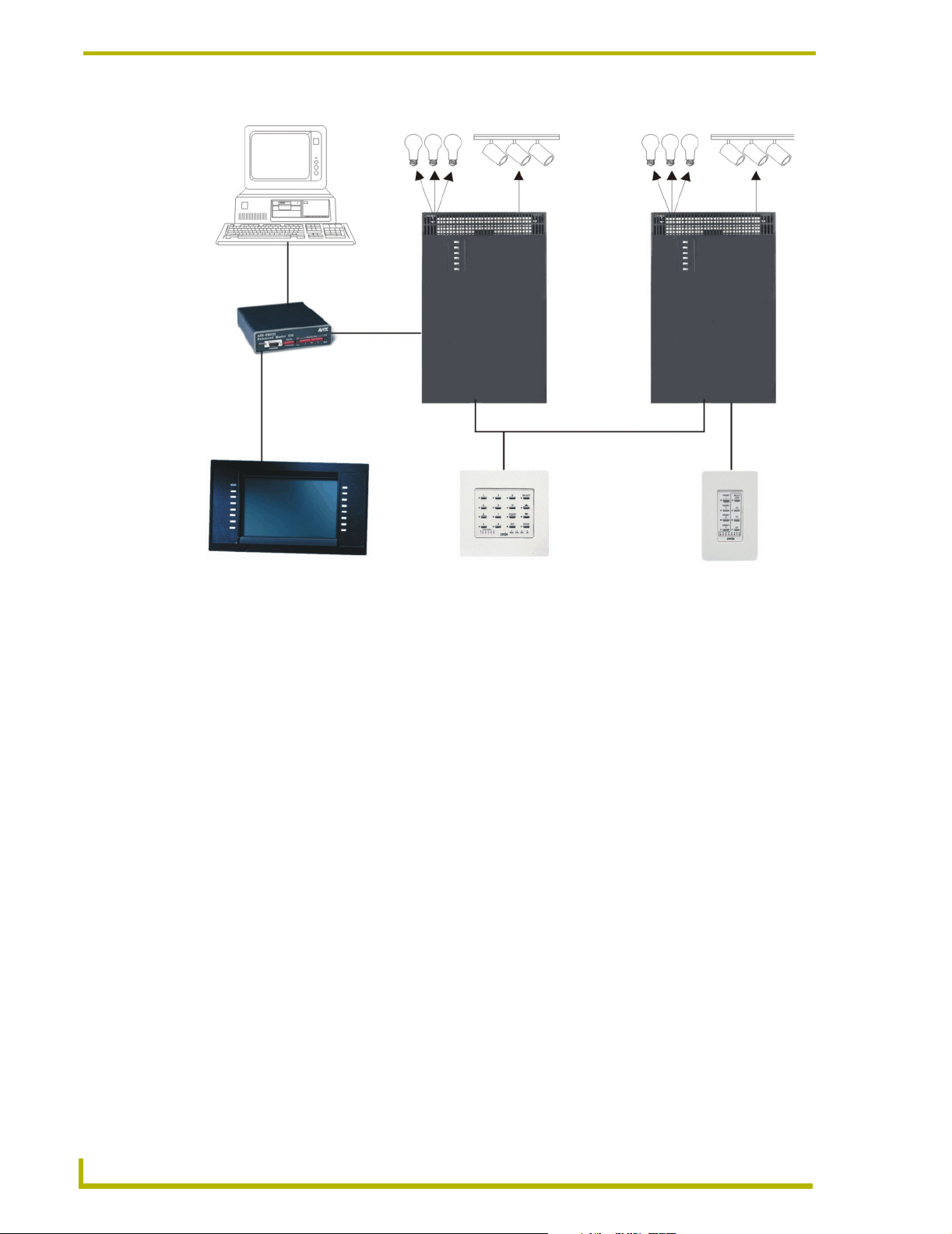
Introduction
RS-232
AXB-EM232
AXlink
AMX Lighting
Pack 1 Pack 2
Controllers
AXlink
Touch panel
FIG. 1 Sample AMX Lighting Control System
Wall panel
PROlink
PROlinkPROlink
Wall panel
PROlink wall panels
PROlink wall panels are available for direct connection to the AMX Lighting system. PROlink
panels do not rely on an AXlink connection. PROlink panels have an internal fixed program that is
powered from the PROlink connector on the AMX Lighting controller. These panels get power
from the power supply available to the controller where the panel is connected. These panels reflect
changes made to the AMX Lighting system by the Axcess system when the AMX Lighting
Controllers are also connected on AXlink.
Lighting Systems
AMX Lighting systems are based on a modular construction. There are three basic components to
the modular structure: Controller, Enclosure, and Dimmer/Switch Modules. All AMX Lighting
controllers have six channels of control. Seven channels of control will always require the use of
two controllers.
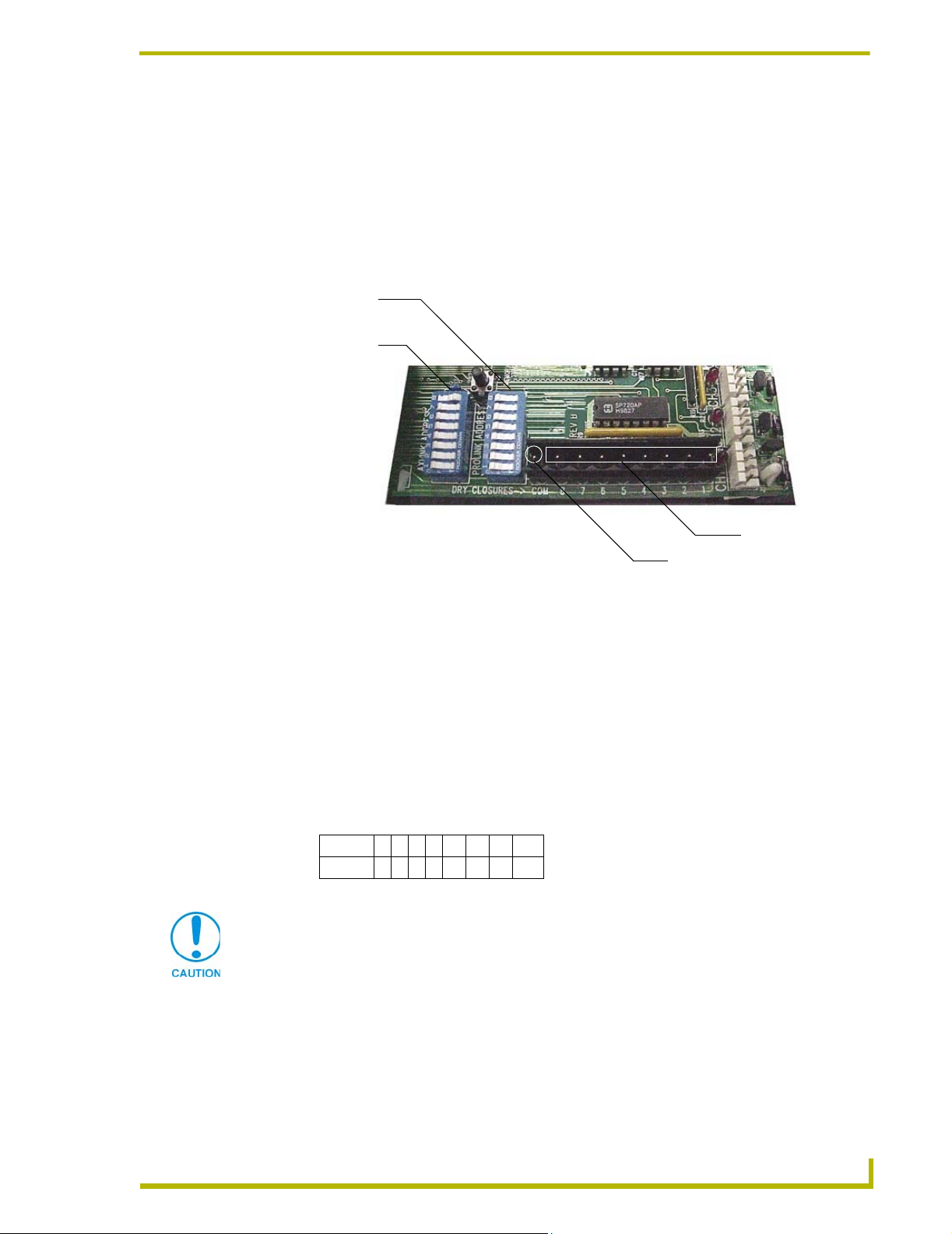
In order to have the controllers address different dimmers ranges, they have a DIP switch installed
to address each pack/group of six channels to a specific range. Changing the PROlink DIP switch
address (value) is a means of differentiating the various dimmers. All AXlink devices also have an
address DIP switch to set a unique ID from 1 to 255. FIG. 2 shows a sample AMX Lighting
controller and its internal components.
2
AMX Lighting PROlink/AXlink Programming
Page 11
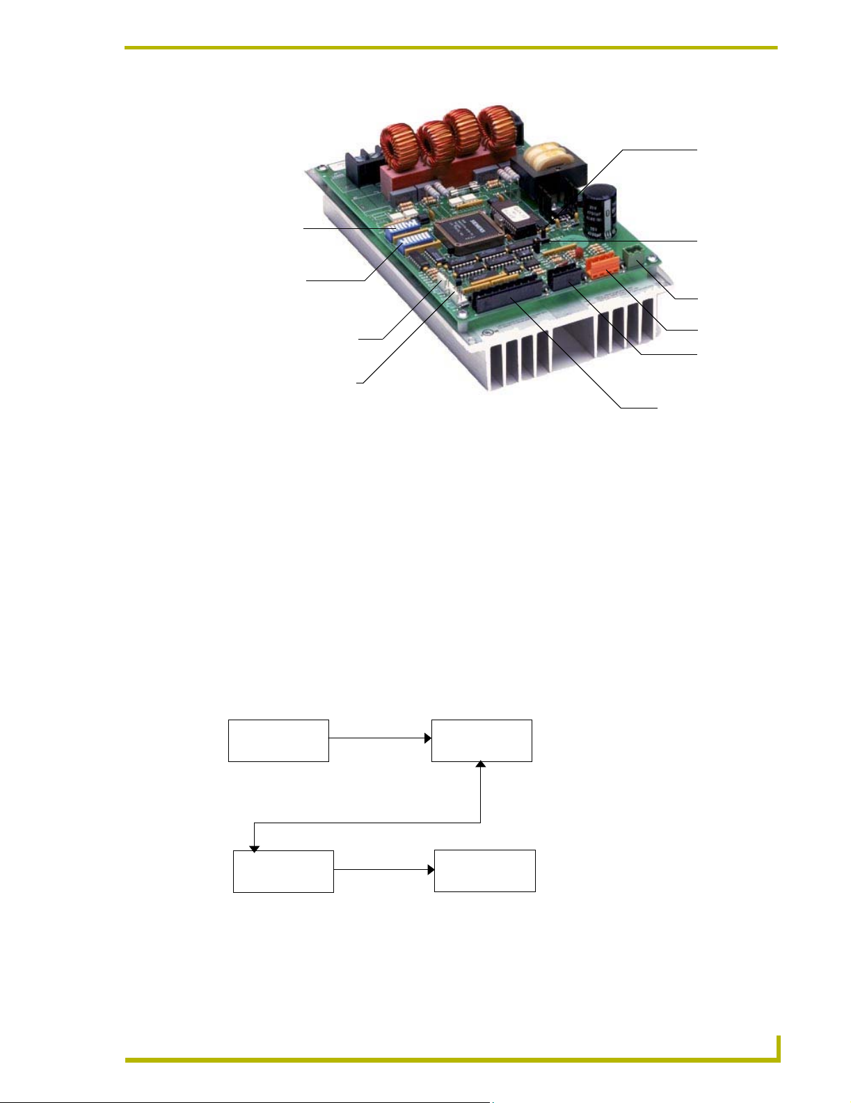
AXlink device
number DIP
switch (SW1)
PROlink device
number DIP
switch (SW2)
Introduction
Reset
Memory
Protect
Powe r
CH5 connector for
optional satellite module
CH6 connector for
optional satellite module
FIG. 2 RDD-DM low-voltage connections and DIP switches
PROlink
AXlink
Dry Closure
The first of a ten pack PROlink system can have one of the 255 AXlink addresses. That means that
a single AXlink address can control 60 channels of dimming or an entire PROlink system. Refer to
the DIP switch configuration subsection for more detailed information about both the PROlink and
AXlink pack numbers.
Axcess Statements
Axcess Send_Command statements are received in the AXlink buffer, processed and sent to the
PROlink buffer where they are translated to the dimming engine. The same is true in reverse, such
that the dimming engine updates the PROlink buffer that sends data to the AXlink buffer and then
to the AXlink Central Controller.
FIG. 3 shows the pathway of the Axcess commands to the dimming engine.
AXCESS
Send_Commands
Statements
received
AXlink
buffer
PROlink
buffer
Commands are
translated then
FIG. 3 Flowchart for Axcess Send_Commands to dimming engine
MX Lighting PROlink/AXlink Programming
Commands
processed and
transmitted
Dimming
engine
transmitted
3
Page 12

Introduction
All this communication takes milliseconds of time. The AXlink buffer sends data to the PROlink
buffer, receives commands from the PROlink buffer, receives data from the Axcess Central
Controller, and connects AXlink levels to an Axcess Central Controller. Each Central Controller
can control over 250 devices on the AXlink control bus. There is a DIP switch on each AXlink
device to set the address from 1 to 255. Each AXlink Central Controller can receive 8 levels from a
device. AMX Lighting pack #1 can send all six of its levels directly to the AXlink bus. Only Pack
#1 can send AXlink levels; Pack 2-10 cannot return direct levels to the Axcess Central Controller.
Programming Commands
There are four main types of programming commands used in the AMX Lighting system: Setup,
Recording, Status, and Operation commands. The following descriptions apply to both the PROlink
and AXlink Command Structure.
Setup commands
These types of commands are global commands sent to Pack #1 that affect the entire PROlink
network. These commands are used to set the default values and parameters that are typically
entered at the startup of the system and not changed. If certain commands are issued with a time
value associated then the AMX Lighting system will use an available default value determined at
setup. The commands for recording and recalling presets use these defaults, as do ramping
operations. Curve settings are setup commands done on a individual channel basis and are not
global. Curves are set in the beginning and do not need to be changed unless the loads also change.
Recording commands
These commands send preset data to the AMX Lighting memory chip. All recording and setup
commands are stored in non-volatile memory. These commands are also used to store presets,
assign presets for dry closure recall, and erase stored presets.
Status commands
Status commands allow a user or a program to get data from the lighting system and act on that
information. This feature gives a computer the ability to perform interactive processes with the
AMX Lighting system. AXlink status data and Axcess Levels have unique differences from
PROlink status data. The combination of AXlink and PROlink status commands provides the
greatest flexibility.
Operation commands
This is the largest category of commands. The operational commands are used for real-time
lighting control and setup of scenes prior to programming presets. Operational commands recall,
ramp, and set levels for dimmers. They can also be used for remote operation of the dry closure
contact.
Control Curves
There is a great influx of new lamps and ballast on the market. Each one has properties and
dimming characteristics that present a new challenge for the dimmer manufacturer to provide an
appropriate dimmer. What was designed as a standard incandescent dimmer must now be able to
control electronic ballast, incandescent lamps, low voltage track lighting, and a host of new
transformers.
4
AMX Lighting PROlink/AXlink Programming
Page 13
Introduction
One way to solve many of these problems is to apply different control curves to each dimmer and to
provide a variable low-end cutoff point.
A dimming curve is a graphical or electronic representation of the amount of control that must be
applied to a dimmer in relation to the dimmer output. It is like a directional map that the controller
follows. The amount of control is typically measured in percent; from an Off-state of level 0 to an
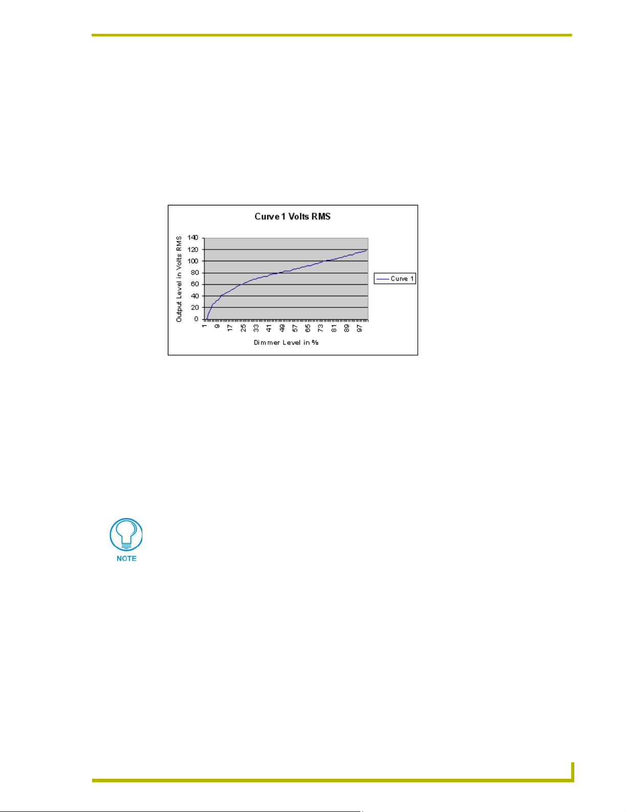
On-state at level 100. Dimmer output is measured in volts. A graphical representation of a dimming
curve is usually the percentage of dimming in relation to the output voltage (RMS) of the dimmer
connected to a standard load. FIG. 4 shows a sample dimming curve.
FIG. 4 Sample dimming curve
Sometimes a fixture or lamp has a problem dimming down to a low range. When this happens the
lights can flicker and cause unwanted dimming performance. To correct for anomalies in the
dimming performance of various devices, the AMX Lighting controller has provisions to
individually set a low-end trim for each of the six dimming channels. The AMX Lighting dimming
system employs a low-end cutoff that allows the dimmer to turn on to a specified level or to dim
down to a specific level. The level at which the dimmer turns on is called the Low End Setting. Low
End commands prevent the dimmer from going below a set threshold. They also force the dimmers
on to the preset threshold. That is useful for some transformer loads and track lights.
Refer to Appendix C: AMX Lighting Curves for more information.
MX Lighting PROlink/AXlink Programming
5
Page 14

Introduction
6
AMX Lighting PROlink/AXlink Programming
Page 15
Pre-Installation Settings
8
Dry Closures
Each AMX Lighting controller has a 9-pin captive screw connector for use as a dry closure input.
One connection is for a common ground and the rest are for the eight dry closure inputs.
AXlink device number
DIP switch (SW1)
PROlink pack number
DIP switch (SW1)
Pre-Installation Settings
Dry closure inputs 1-
Common Ground (COM)
FIG. 5 Sample dry closure connector
The inputs are an open collector pulled up to 5 VDC. The status is normally open, channel Off,
closure released. When an input is pulled low to ground and falls below 3 VDC, the AMX Lighting
system sees the action as an input closure and the AXlink channel is turned On and a push sent to
the Axcess Central Controller.
Configuring and connecting AXlink
The DIP switch SW1 sets the AXlink device number. The device number is determined by the
value of all the switch position settings. The following table shows the SW1 DIP switch positions
and their values. The device number assignment range is 1 through 255.
Position12345678
Value 1 2 4 8 16 32 64 128
Power Off the unit before setting the DIP switch
To set DIP switch SW1 and connect AXlink:
1. Power Off the unit at the circuit breaker.
2. Locate the SW1 DIP switch (marked AXLINK ADDRESS) and set the device number using
the values shown above.
MX Lighting PROlink/AXlink Programming
7
Page 16
Pre-Installation Settings
r
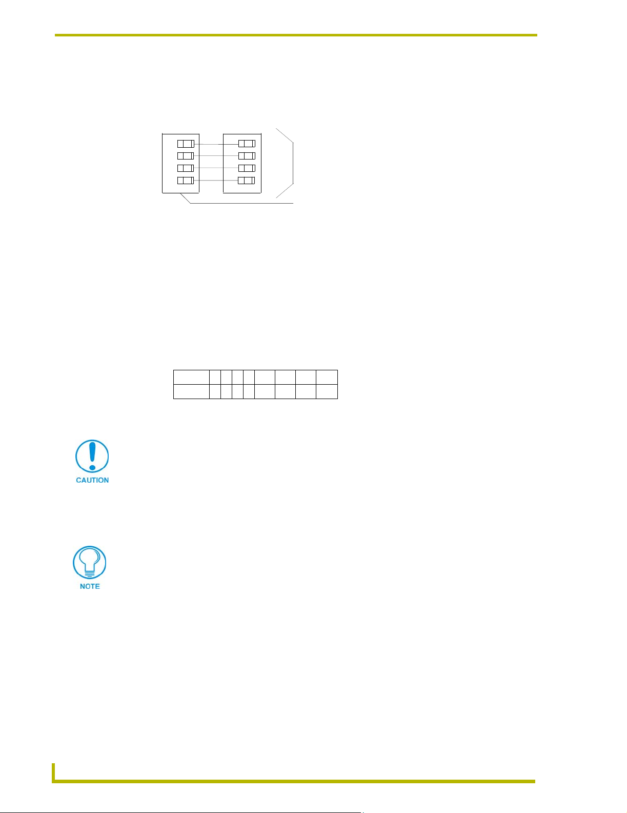
3. Connect the four-pin AXlink male connector onto the four-pin female AXlink connector in the
AMX Lighting Controller. FIG. 6 shows how to wire the AXlink connector to a Central
Controller.
PWR +
AXP/TX
AXM/RX
GND -
FIG. 6 AXlink wiring diagram
PWR +
AXP
AXM
GND -
Central Controlle
AXlink connector
4. Power up the AMX Lighting Controller at the circuit breaker panel or push the Reset Button.
Configuring and connecting PROlink
DIP switch SW2 sets the PROlink pack number. The pack number is determined by the value of all
the switch position settings. The following table shows the SW2 DIP switch positions and their
values. The pack number assignment range is 1 through 10. The lighting system will not work if
you assign pack numbers outside of the range. DIP switch #8 is a test switch. It will turn all the
lights to full in the On position. It must be in the Off position for normal operation.
Position12345 6 7 8
Value 1 2 4 8 N/A N/A N/A Test
To set DIP switch SW2 and connect PROlink:
Power Off the unit before setting the DIP switch
1. Power Off the unit at the circuit breaker.
2. Locate the SW2 DIP switch and set the pack number using the values shown above. The pack
number must be 1 to 10.
Assign pack #1 for all communications, diagnostics, and response (feedback).
3. Connect the four-pin PROlink male connector into the four-pin female PROlink connector in
the AMX Lighting Controller. FIG. 7 shows how to wire the PROlink connector to a PROlink
wall panel.
8
AMX Lighting PROlink/AXlink Programming
Page 17
Pre-Installation Settings
+12V
PR+
PR-
GND
FIG. 7 PROlink wiring diagram
+12V
PR+
PR-
GND
PRO-SP8 wall panel
Panja Lighting PROlink connector
Connecting dry closures
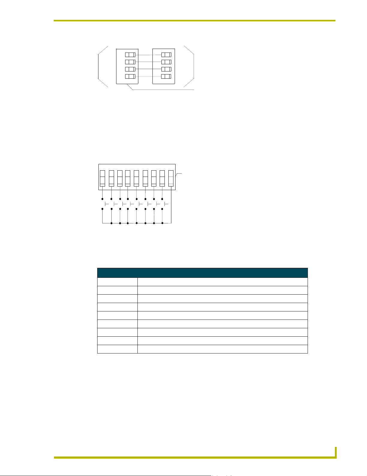
Eight connections are available for dry contact closures and one common reference point. FIG. 8
shows the standard wiring configuration for the 9-pin dry closure connector.
C
O
1
2 3 4 5 6 7 8
M
9-pin dry closure
connector
FIG. 8 9-pin dry closure connector (standard configuration)
Each contact closure connection (1 through 8) is pre-programmed with a default preset. The
following table shows the default presets for each contact closure.
Default Dry-Closure Presets
Contact closure Default presets & functions
1 Preset 1, Channel 1 at 100% in 1 second*
2 Preset 2, Channel 2 at 100% in 1 second*
3 Preset 3, Channel 3 at 100% in 1 second*
4 Preset 4, Channel 4 at 100% in 1 second*
5 Preset 5, Channel 5 at 100% in 1 second*
6 Preset 6, Channel 6 at 100% in 1 second*
7 Preset 7, Channel 1 - 6 at 100% in 1 second*
8 Preset 8, Channel 1 - 6 at 0% in 1 second*
Dry closure method to reset Default Settings
The default settings can be restored using the Dry Closure Input connection. By wiring all nine pins
(input pins 1-8, and the COM pin) together and plugging it into the Dry Closure port on a control
card for one minute will reset all default settings and parameters to the factory default settings as
listed previously.
To reset a AMX Lighting controller to default mode:
1. Power Off the AMX Lighting controller at the circuit breaker panel.
MX Lighting PROlink/AXlink Programming
9
Page 18
Pre-Installation Settings
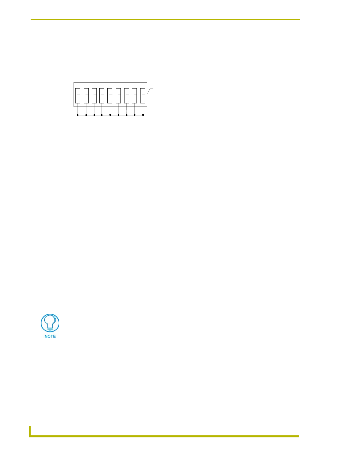
2. Disconnect all AXlink and PROlink cables from the controller module.
3. Connect a jumper to the dry contact closures 1 through 8 and to ground as shown in FIG. 9.
1
2 3 4 5 6 7 8
FIG. 9 9-pin dry closure connector set to default mode
C
O
M
9-pin dry closure connector
4. Power up the controller and wait for the controller's green status LED to go off after about one
minute.
5. At the breaker panel, remove power from the controller again.
6. Remove the 9-pin connector from the Dry Closure connector.
7. Reconnect AXlink and PROlink.
8. Reapply power to the AMX Lighting controller.
Default Settings and Parameters
There are several default settings involved with the AMX Lighting controller. There are default
values for recalling a preset, going to a specified level, ramping up or down a dimmer or preset,
which presets are stored for dry closure recall, and enabling PROlink response and feedback
strings. Once a default parameter is set it does not have to be changed for the life of the system.
These settings are stored in non-volatile memory in a separate memory chip. The first 8 presets are
defined in the default startup, and these presets are also attached to the default dry closures. The
eight dry closures will recall the first 8 presets. All default values and the clearance of all other
presets can be accomplished using a special function of the dry closure connector. All channels are
cleared of any low-end trim during a factory reset of the processor. The pack will report,
CP01:000,000,000,000,000,000 designating all channels be cleared of low-end settings. By
connecting a jumper to dry contacts 1-8 and to the common ground, the factory default mode erases
all existing presets stored in memory.
10
The symbol C is obtained by pressing ALT+ 012, entering the Hexadecimal value $0C, or by
entering the decimal number 12.
AMX Lighting PROlink/AXlink Programming
Page 19
Pre-Installation Settings
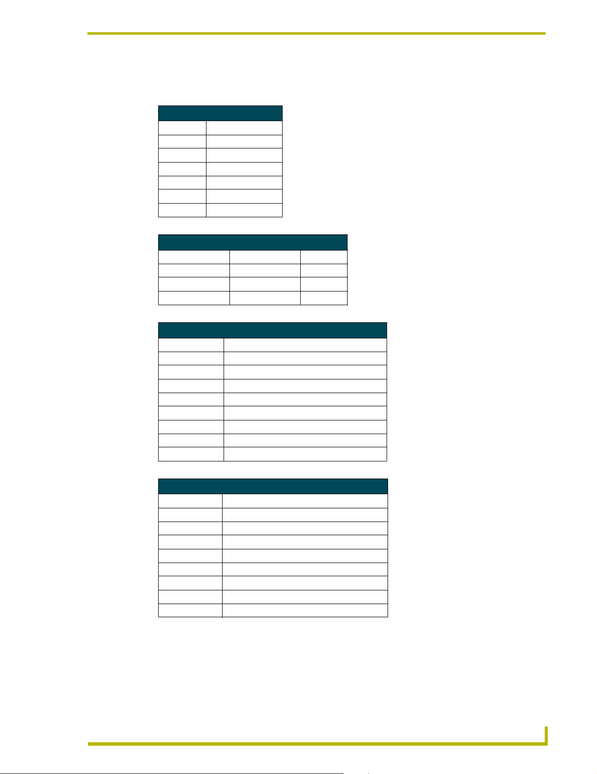
The following tables shows the default low-end settings, default preset time values, default dryclosure presets and factory presets for AMX Lighting:
Default Low-End Settings
Function Low-end setting
Channel 1 LE=0
Channel 2 LE=0
Channel 3 LE=0
Channel 4 LE=0
Channel 5 LE=0
Channel 6 LE=0
Default preset time values
Firmware version Function Time Value
2.0 or greater Default ramp time 6
Default level time 1
Default preset time 3
Default dry-closure presets
Contact closure Default presets & functions
1 Preset 1, Channel 1 at 100% in 1 second*
2 Preset 2, Channel 2 at 100% in 1 second*
3 Preset 3, Channel 3 at 100% in 1 second*
4 Preset 4, Channel 4 at 100% in 1 second*
5 Preset 5, Channel 5 at 100% in 1 second*
6 Preset 6, Channel 6 at 100% in 1 second*
7 Preset 7, Channel 1 - 6 at 100% in 1 second*
8 Preset 8, Channel 1 - 6 at 0% in 1 second*
Factory presets
Preset number Description
1 Channel 1, Channel 1 at 100% in 1 second*
2 Channel 2, Channel 2 at 100% in 1 second*
3 Channel 3, Channel 3 at 100% in 1 second*
4 Channel 4, Channel 4 at 100% in 1 second*
5 Channel 5, Channel 5 at 100% in 1 second*
6 Channel 6, Channel 6 at 100% in 1 second*
7 Channel 1 - 6 at 100% in 1 second*
8 Channel 1 - 6 at 0% in 1 second*
MX Lighting PROlink/AXlink Programming
11
Page 20
Pre-Installation Settings
Wiring Considerations
The following information relates to wiring considerations for a AMX Lighting system.
Do not connect power to the device until the wiring is complete.
Preparing/connecting captive wires
1. Strip 0.25 inch of wire insulation off all wires.
2. Insert each wire into the appropriate opening on the connector according to the wiring
Axcess Control - PC to Axcess Controller
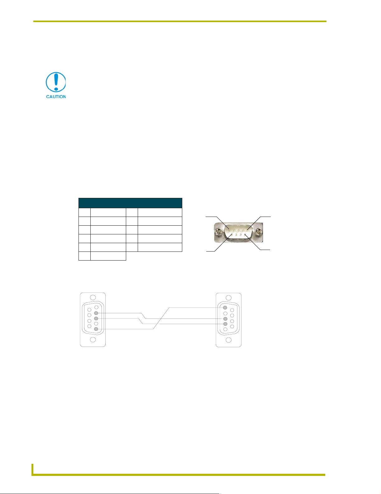
The following table lists the pinout information for the DB-9 connector.
DB-9 Connector Pinouts
Pin Signal Pin Signal
1 N/A 6 N/A
2RXD 7RTS
3TXD 8CTS
4 N/A 9 N/A
5GND
diagrams and connector types described in this section.
! Do not tighten the screws excessively; doing so may strip the threads and damage the
connector.
Pin 1
Pin 6
Pin 5
Pin 9
FIG. 10 shows a DB9 pinout relation from the computer to the Axcess Central Controller.
Connection view
5 (GND)
2 (RXD)
3 (TXD)
5 (GND)
Computer COM Port
DB9 (9-Pin Female)
FIG. 10 Computer to Axcess connection
3 (TXD)
2 (RXD)
AXCENT
DB-9 (9-Pin Female)
3
Pro Program Port
Use cable FG #10-727 to connect computer the COM port to Axcess or AXCENT Program Port.
12
AMX Lighting PROlink/AXlink Programming
Page 21

AXlink wiring between multiple devices
FIG. 11 shows AXlink wiring between AXlink devices.
Pre-Installation Settings
AXP
AXM
DEV.#3
PWR
P+
M-
GND
AXP
AXM
DEV.#1
PWR
P+
M-
GND
FIG. 11 Multiple AXlink wiring connections
DEV.#2
AXP
AXM
PWR
P+
M-
GND
Disconnect the main power to the AMX Lighting controller if rewiring the AXlink cables.
PROlink wiring between multiple devices
FIG. 12 shows PROlink wiring between PROlink panels and controllers.
PRO-SP8
+12
PR
PR-
GND
FIG. 12 Multiple PROlink wiring connections
Panja Lighting Controller 1
+
+12
PR+
PR-
GND
Panja Lighting Controller 2
+12
+
PR
PR-
GND
Disconnect the main power to the AMX Lighting controller if rewiring the PROlink cables.
Power considerations
The following information relates to wiring considerations for a AMX Lighting system.
Power connections
Power to a controller must be maintained to avoid losing communication with AXlink. Pack #1 will
survive a brownout or temporary loss of power and recover online to AXlink. Reset Pack #1 to
bring Packs #2 and above online. If Pack #1 loses power and power is then restored, all other packs
(2 - 10) will remain offline until Pack #1 is reset.
AXlink connections
In order to establish an AXlink connection for programming, the controller must be connected to a
power source and be powered on. The AMX Lighting system will allow programming after power
has been applied. Once power has been applied and the AMX Lighting controller has established an
AXlink connection, the 12VDC supply to the processor will allow program changes if the 120VAC
supply is cut off.
MX Lighting PROlink/AXlink Programming
13
Page 22

Pre-Installation Settings
14
AMX Lighting PROlink/AXlink Programming
Page 23

Programming Strings
Strings
A string is a set of values grouped together with single and/or double quotes. Character arrays
(strings) are enclosed between double quotes while ASCII strings are enclosed within single
quotes. All ASCII strings are character arrays. If an ASCII string needs to be sent with non-ASCII
characters, it must first be enclosed in double quotes and then the non-ASCII characters must be
delineated with commas. Axcess looks at:
• ASCII characters These characters are surrounded with single quotes.
• Hexadecimal characters These characters begin with a $. An example is $0D that acts as a
carriage return and enters the information.
• Decimal characters These characters are numerical and are not enclosed with any quotation but are separated from other types of characters by a comma.
PROlink Programming Strings
PROlink accepts ASCII commands from the AXlink connection. These commands take the form of
a Send_String command to the AXlink device. Most commands are terminated with a carriage
return. A carriage return is represented by the decimal value 13 or the hexadecimal form $0D.
Response (feedback) values for presets, time values, and dimmer levels are usually three characters.
The AMX Lighting controller is both an AXlink and PROlink device. You can send PROlink
commands through the AXlink COM port, but you cannot send AXlink commands to the PROlink
port.
Programming Strings
A sample command structure is shown below:
•Example:
•Example 2:
• PROlink response example:
SEND_STRING <device>,"'<command string>', <CR>"
Send_String LTS, "'RT5', 13"
CRAMPTIME SET AT 005
The 'RT5' are ASCII characters and the '13' are decimal characters. Everything within the double
quotes gets sent out when followed with a carriage return, <CR> like $0D.
The ASCII character C or $0C precedes all responses from the AMX Lighting controller. The
PROlink response will have a carriage return $0D and a line feed $0A at the end of each response.
For example purposes the <device> is always named 'LTS' and the <CR> will be substituted with
the Decimal numerals 13. Levels are expressed in percent from level 0 (zero) to 99 with full On or
100% expressed as two characters, FF.
In the command format, such as the one shown below, the <n> parameter refers to the individual
dimmer number or group of dimmers. The value <n> can be in the range from 1 to 60. It can be
expressed as a compound number using the - (dash) and & (ampersand). The letter A for ALL
('include all 60 dimmers') is also valid as a value for <n>. The string '1&3-6&9L99' is an example
of a compound group consisting of dimmers 1, 3, 4, 5, 6, and 9. The example string 'AL0T0' would
send all 60 dimmers to level 0 instantly. The following is a generalized PROlink command structure
example:
MX Lighting PROlink/AXlink Programming
15
Page 24

Programming Strings
PROlink commands should not be sent while the PROlink buffer is responding to the previous
command or a data collision could occur. In Axcess programs there should be at minimum a 3/10sec. wait (WAIT 3) between commands sent to the controller. Repetitive commands should have a
½ second wait (WAIT 5) between commands for greater accuracy. The dimmers all have the ability
to turn On or Off in 1/10 of a second.
A <CR> or '13' is sent before a command string will also clear the PROlink buffer allowing more
reliable data transfer.
A dimmer or group of dimmers can be excluded from a preset using the 'Undefined' command.
Undefined is a level command that allows a dimmer to be ignored during the recording of a preset;
it has no defined level. A preset can be created where dimmers 1 and 2 can be set to 50% while
dimmers 3 and 4 are set to undefined levels.
PROlink Command Structure
Sample format:
Variables: • <n>: This is the dimmer number from 1-60 (Any combination of dimmers
Example:
PROlink response example:
Send_String <device>, "'<n>L<m>T<t>', 13"
• <m>: This is the dimmer level percentage 0-100
• <t>: This is the time value, 0-255 in seconds
Send_String LTS, "'1L57T3', 13"
C001 LEVEL 57 IN 003
The following example shows a command line where any undefined dimmers wouldn't be included
in a preset:
•Example:
• PROlink response example:
Send_String LTS, "'3-4LU'"
CGROUP LEVEL UN IN 000
If all lights were on full before this preset was recalled, then only dimmers 1 and 2 would go to 50%
while dimmers 3 and 4 would stay at full. This is useful where one AMX Lighting enclosure must
service several rooms or when a preset is needed for only one light in the entire room. The 'All
Levels Undefined' command is often used before recording a preset to clear the scene to a 'neutral'
level. A preset stored with all levels undefined will have no affect on the dimmers when recalled.
AXlink cannot 'Undefine' a single channel.
The following example shows a command line where any undefined dimmers wouldn't be included
in a preset.
•Example:
• PROlink response example:
Send_String LTS, "'ALU', 13"
CALL LEVEL UN IN 000
16
Use this type of preset to initiate unique actions that do not change the lighting. All unique action
presets can be assigned to AXlink, PROlink, or dry closure panels. This allows any AMX Lighting
panel to do non-lighting functions. A non-lighting preset could be used to turn on music or set an
alarm. A preset using all levels undefined will still be counted as one of the available 128 presets
and there can be many presets that do nothing to the lights.
AMX Lighting PROlink/AXlink Programming
Page 25

Programming Strings
There are three special presets in AMX Lighting controllers that have a fixed, non-programmable
function. Special preset #255 ramps a preset down; preset #254 ramps a preset up; and preset #253
allows dry closures to record presets. All special presets can be stored and recalled just like the
other 128 standard presets. The addition of preset ramping as a preset was most useful for dry
closures, giving them the ability to raise or lower lighting levels using simple switches.
Preset ramping can raise or lower all the levels in a preset in a proportional manner. Preset ramping
gives you the ability to raise all the levels to 100% or lower all the levels to 0. The preset will retain
its proportional levels after it has been raised or lowered to an extreme level (0 or 100). If a preset is
raised to all levels equal 100%, then it can be lowered back to its original state with all levels in
proportion to the others. If a preset has channel 1 at 75% and channel 2 at 90%, then ramping the
preset up 10% will put channel 1 at 85% and channel 2 at 100%; then ramping down 20% will put
channel 1 at 65% and channel 2 at 80%. All presets can be recovered after ramping the preset to an
extreme level. This is useful for incremental changes to an entire scene.
All presets and startup features are stored in a separate non-volatile memory chip. The memory
protect jumper on each control card will physically prevent the memory chip from being updated,
or accidentally erased. If the Memory Protection jumper is installed the AMX Lighting controller
will still react like it has changed or stored the new preset without actually doing so. This can be a
potential source of confusion. There is no digital command to determine if the jumper is in place or
not.
AXlink Programming Strings
Earlier lighting products communicated via RS232 that required them to use Send_Strings. More
recent lighting products began to use AXlink cable to communicate on an AXlink bus.
Send_Commands, channel and level information was also added to the programming language.
PROlink uses Send_Strings such as "13, $0D, 'S'" where decimal, hexadecimal, and ASCII
characters are used respectively. AXlink uses Send_Commands such as SEND_COMMAND LTS.
The relation between the two is that the current Axcess language used in AMX Lighting integrates
the two. For example:
SEND_COMMAND <device>, '<Send_String>'
As Axcess processes a string expression, it evaluates each member of the expression from left to
right, and the result is a complete string.
Levels
The best way to get levels from the AMX Lighting controller is to use the AXlink level feature built
in to each AMX Lighting controller. Use the DEFINE_CONNECT_LEVEL feature for touch panel
and wall panel bargraphs. The CREATE_LEVEL command feature can be used to display the 8-bit
AMX Lighting level or to use the level on other AXlink 8-bit level devices like the AXB-VOL3
box, a text window, or the AXB-DMX512 controller.
Active bargraphs on touch panels tend to raise or lower lights in uneven steps. The size of the active
bargraph does not lend itself to smooth dimming, especially at the top or bottom of the slider. The
preferred way would be to use Up and Down arrows or commands, and to put bargraphs in display
mode only.
Polling the AMX Lighting controller for levels is the least effective way to get and display levels;
this is not recommended.
MX Lighting PROlink/AXlink Programming
17
Page 26

Programming Strings
To determine if a AMX Lighting level is in the 'UNDEFINED' state you must use the PROlink
string command for single dimmer status as described in PROlink - Status section under the
heading 'Dimmer status'. The AXlink layer could report a level as FF (all on), but at the same time
the PROlink layer has assigned that channel as 'UNDEFINED'; this will make a difference when
recording presets. Presets are stored using the PROlink layer, not the AXlink layer.
Levels are returned in AXlink as an 8-bit figure with 256 steps from 0 to 255. Use the formula
x = (x*100/255) [where x is the dimmer level] to express an 8-bit level in percent. This will give an
approximate percentage level, with a 1% accuracy.
Buffers
The recommended way to determine a AMX Lighting response to a buffer is to use this format:
There are a few constants that may help in PROlink string manipulation. Presets use the 'GOTO'
command, levels are preceded by the word 'LEVEL', and time values are preceded by the word 'IN'.
Refer to the Create_Buffer subsection on more information on creating a buffer.
LTS_RESPONSE = REMOVE_STRING (LTS_BUFFER,"13,10", 1) '
Responses
The responses from the AMX Lighting controller can be turned Off in order to quickly send
commands. Commands can be sent faster if there is no waiting for a response after each command
is sent. The default mode at startup is RXON, which will allow responses to be sent from the AMX
Lighting controller. It is recommended to send a command and wait for the response, then send
another command. Use the RXOFF mode to avoid data collisions. This will disable most of the
return responses from PROlink and speed up the data transfer rate. It will also stop all feedback.
Dry Closures
Dry closures are read in sequential order and are assigned to AXlink channels 147 - 154. If two
buttons are pressed simultaneously, only one channel will be active. Buttons on closures must be
pushed sequentially to have more than one channel active. Pushing dry closure #1, then #2, then #3
will activate all three channels (AXlink channels 147, 148, 149). All eight closures can be used at
once.
18
AMX Lighting PROlink/AXlink Programming
Page 27

PROlink Command Structure
Setup Commands
These commands are used to set the default values and parameters that are typically entered at the
startup of the system and not changed.
! For example purposes the <device> is always named 'LTS' and the <CR> will be
substituted with the ASCII numerals 13.
Setting a Default Level Time
PROlink Command Structure
LT
Level Time is the time it takes for a level to change from its present state to a
new level when using a Level command. If a level command is sent without the
time value specified (T), the dimmer will go to the specified level using the
Default Level Time.
The factory default for this value is 1 second
Send_String LTS, "'LT<t>', 13"
Var iabl es:
• <t>: Fade time, 0-255 in seconds
Example:
Send_String LTS, "'LT1', 13"
PROlink response:
CLEVEL TIME SET AT 001
Setting a Default Ramp Time
RT
Ramp Time is the time it takes to raise or lower the channel or preset from its
preset levels to either extreme of level zero or 100%. All ramp commands will
use the Default Ramp Time. Individual dimmers cannot have individual ramp
rates
Send_String LTS, "'RT<t>', 13"
Var iabl es:
• <t>: Fade time, 1-255 in seconds, zero is not valid
Example:
Send_String LTS, "'RT5', 13"
PROlink response:
CRAMPTIME SET AT 005
MX Lighting PROlink/AXlink Programming
19
Page 28

PROlink Command Structure
Setting a Default Preset Time
PT
Preset Time is the time it takes for a preset to be recalled. If a preset is stored
or recalled without the time value specified (T), it will be recalled or stored
using the Default Preset Time.
The factory default for this value is 3 seconds
Send_String LTS, "'PT<t>', 13"
Var iabl es:
• <t>: Fade time, 0-255 in seconds
Example:
Send_String LTS, "'PT3', 13"
PROlink response:
CPRESET TIME SET AT 003
Enabling a PROlink response
RN
Response On: PROlink acknowledges each command with a response. This
command will enable responses to the AXlink master, and it is the default startup condition.
Send_String LTS, "'RN', 13"
Example:
Send_String LTS, "'RN', 13"
PROlink response:
CRXON MODE
Disabling a PROlink response
RF
Response Off: PROlink acknowledges each command with a response. This
command will disable responses to the AXlink master and speed up communication.
Send_String LTS, "'RF', 13"
Example:
Send_String LTS, "'RF', 13"
Phase/zero-crossing detection and correction
P
Phase/zero-crossing detection and correction features at startup and reset.
In the presence of a phase/zero-crossing error:
• The green AXlink LED on the Radia will blink very fast.
• The Radia will add a "P<pack#> PHASE ERROR" to any command response.
The current state of the phase/zero-cross detection system can be queried on a pack by
pack basis.
Syntax:
<pack#>Y
Return:
P<pack#>PH: (OK or FAIL)
1(Y or N), 2A(Y or N), 2B(Y or N), 3(Y or N)
A correctly working system will dislplay OK,Y,Y,Y,Y. A failure would read: PH: FAIL and an
N following the <phase #> in question
20
AMX Lighting PROlink/AXlink Programming
Page 29

PROlink remote reboot
PROlink Command Structure
QQQ
The command triggers execution equivalent to start-up or activation of reset button.
Syntax:
<pack#>QQQ
Setting a Curve
A curve is used to match the channel level setting with the dimmer output. A curve can be used to
govern the amount of dimming control relative to the level setting allowing for uniform dimming
between different loads.
Format: Send_String LTS, "'<n>/<c>', 13"
Variables: • <n>: Dimmer number from 1-60, and All
• <c>: Curve selection from 1-9, A-F, N, O
Example 1:
PROlink response: C01 CURVE 1
Example 2: Send_String LTS, "'1&2/6', 13"
PROlink response: CGROUP CURVE 6
Send_String LTS, "'1/1', 13"
Setting a Low End voltage
The Low End setting allows a programmer to set the initial turn On voltage. The dimmer will ramp
up to the Low End threshold at Level 1 and stay there until the LE command releases the threshold
and allows normal dimming. This is also used to prevent certain loads from dimming below the
product's ability. They only ramp down to a set level and stay there until it reaches level 0.
Format: Send_String LTS, "'<n>LE<m>', 13"
Variables: • <n>: Dimmer number from 1-60, and All
• <m>: Dimmer level percentage (0-100)
Example 1:
PROlink response: CMINIMUM LEVEL IS: 007
Example 2: Send_String LTS, "'1-6LE3', 13"
PROlink response: CMINIMUM LEVEL IS: 003
Send_String LTS, "'1LE7', 13"
Recording Commands
These commands send preset data to the AMX Lighting controller memory chip. All recording and
setup commands are stored in non-volatile memory. These commands are also used to store presets,
assign presets for dry closure recall, and erase stored presets.
MX Lighting PROlink/AXlink Programming
21
Page 30

PROlink Command Structure
Recording Presets
If the value for <t> is not entered, the AMX Lighting controller will use the value specified by the
Default Preset Time. The <t> parameter is optional.
Format:
Variables: • <s>: This is the preset number
Example 1:
PROlink response:
Example 2:
PROlink response:
Send_String LTS, "'<s>R<t>', 13"
• <t>: This is the ramp rate, 0-255 in seconds
Send_String LTS, "'4R2', 13"
CRECORD 004 IN 002
Send_String LTS, "'4R', 13"
CRECORD 004 IN 003 (default time=3)
Recording Dry Closure Presets
Special presets #253, #254, and #255 are allowed for the <s> value. These presets allow preset
ramping and enable the record mode.
Format:
Variables: • <p>: This is the pack number 1-10 or A (all)
Special presets: All special presets can be stored and recalled just like the other 128 standard
Example:
PROlink response:
Send_String LTS, "'<p>E<cl>P<s>', 13"
• <cl>: This is the dry closure number 1-8
• <s>: This is the preset number 1-128, 253, 254, 255
presets.
• #253 allows dry closures to record presets
• #254 ramps a preset up
• #255 ramps a preset down
Send_String LTS, "'1E2P99', 13"
CPRST 099 ON PK 01 SW 2
22
Status Commands
Status commands allow a user or a program to get data from the lighting system and to act on that
information.
Obtaining a Dimmer status
This is the fastest way to get dimmers status. It is also the fastest way to see if a computer is
connected to the AMX Lighting controller using the terminal emulator mode in Axcess. Use this
command to determine any undefined channels.
Format:
Variables: • <n>: This is the dimmer number from 1-60 (Only one dimmer at a time)
Example:
PROlink response: CCHAN:01 CURV: 1 LEV: 25
Send_String LTS, "'<n>', 13"
Send_String LTS, "'1', 13"
AMX Lighting PROlink/AXlink Programming
Page 31

PROlink Command Structure
Obtaining a Pack Curve status
This is the fastest way to see the curves in a pack. The PROlink answer gives the pack number
followed by the dimmer curve status starting with dimmer one.
Format:
Variables: • <p>: This is the pack number 1-10 (Only one pack at a time)
Example:
PROlink response: CP01: 1, 1, 1, 6, N, N
Send_String LTS, "'<p>C', 13"
Send_String LTS, "'1C', 13"
Obtaining All the Pack Curve status
This is the fastest way to see the curves in a PROlink system. The PROlink answer gives the pack
curve status starting with pack one, a carriage return, and a line feed, and then the next pack. It does
not report packs that are not on line.
Format:
Example:
PROlink responses: CP01: 1, 1, 1, 6, N, N
Send_String LTS, "'AC', 13"
Send_String LTS, "'AC', 13"
CP02: 1, 1, 1, 6, N, N …
Obtaining a Pack Level status
This is the fastest way to see the levels in a pack. The PROlink answer gives the pack level status
starting with pack one. This command does not identify any undefined channels.
Format:
Variables: • <p>: This is the pack number 1-10 (Only one pack at a time)
Example:
PROlink response:
Send_String LTS, "'<p>Z', 13"
Send_String LTS, "'1Z', 13"
CP01: 25, 37, 00, 00, FF, 88
Obtaining All Pack Level status
This is the fastest way to see the levels in a PROlink system. The PROlink answer gives the pack
levels starting with pack one, a carriage return, and a line feed, and then the next pack. It does not
report packs that are not on line. This command does not identify any undefined channels.
Format:
Example:
PROlink responses:
MX Lighting PROlink/AXlink Programming
Send_String LTS, "'AZ', 13"
Send_String LTS, "'AZ', 13"
CP01: 25, 37, 00, 00, FF, 88
CP02: 00, 22, 99, FF, FF, FF …
23
Page 32

PROlink Command Structure
Obtaining a Pack Low End Setting status
This is the fastest way to see the Low End Settings in a pack. The PROlink answer gives the pack
Low End trim status from the selected pack starting with the pack number, followed by the six
dimmer channels beginning with dimmer one.
Format:
Variables: • <p>: This is the pack number 1-10 or A (all) (Only one pack at a time)
Example:
PROlink response:
Send_String LTS, "'<p>LE?', 13"
Send_String LTS, "'1LE?', 13"
CP01: 000, 005, 000, 000, 005, 000
Obtaining firmware version in PROlink
The PROlink version is useful if a specific Radia is to be queried for its Firmware version.
Format:
Example:
SEND_STRING RADIA," <pack#> `VER', 13"
String From [96:1:1]-[$0C<pack#> VERSION #3.01$0D$0A?] 11:53:29
Operation Commands
Operation commands are used for real-time lighting control and setup of scenes prior to
programming presets.
Recalling Presets
If the value for <t> is not entered, the AMX Lighting controller will use the value stored at the time
the preset was recorded. The <t> parameter is optional. This is the fastest way to have many lights
change levels.
Format:
Variables: • <s>: This is the preset number 1-128, 253, 254, 255
Example 1:
PROlink response:
Example 2:
PROlink response:
Send_String LTS, "'<s>B<t>', 13"
• <t>: This is the ramp rate, 0-255 in seconds (optional)
Send_String LTS, "'3B5', 13"
CGOTO 003 in 005
Send_String LTS, "'3B', 13"
CGOTO 003 in 003 (default time = 3)
Ramping Dimmers Up
The dimmer will continue ramping until the carriage return is sent or until the dimmer reaches level
zero or 100. Ramping is best done on the push, while stopping is done on the release of a button.
Format:
Variables: • <n>: This is the dimmer number from 1-60 or All (Any combination of dimmers)
Example:
PROlink response:
Send_String LTS, "'<n>U'" no<enter>
Send_String LTS, "'1U'"
C01 UP
24
AMX Lighting PROlink/AXlink Programming
Page 33

PROlink Command Structure
Ramping Dimmers Down
The dimmer will continue ramping until the carriage return is sent or until the dimmer reaches level
zero or 100. Ramping is best done on the push, while stopping is done on the release of a button.
Format:
Variables: • <n>: This is the dimmer number from 1-60 or All (Any combination of dimmers)
Example:
PROlink response:
Send_String LTS, "'<n>D'" no<enter>
Send_String LTS, "'1D'"
C01 DOWN
Stop Ramping Dimmers - Method 1
The dimmer will continue ramping until the carriage return or <enter> is sent or until the dimmer
reaches level zero or 100. Ramping is best done on the push, while stopping is done on the release
of a button.
Format:
Example:
PROlink response:
Send_String LTS, "13"
Send_String LTS, "13"
C01 STOP
Stop Ramping Dimmers - Method 2
This command will stop any amount of dimmers. It is useful in stopping individual dimmers during
a long fade.
Format:
Variables: • <n>: This is the dimmer number from 1-60 (Any combination of dimmers)
Example:
PROlink response:
Send_String LTS, "'<n>S', 13"
Send_String LTS, "'1-3&5S', 13"
CGROUP STOP
Stop Ramping for All Dimmers
This command will stop all dimmers. It is the most reliable way to stop the ramping of dimmers.
This command will also stop preset ramping.
Format:
Example:
PROlink response:
Send_String LTS, "'AS', 13"
Send_String LTS, "'AS', 13"
CALL STOP
Ramping a Preset Up
The preset will continue ramping until the carriage return is sent or until the new preset is reached.
Ramping is best done on the push, while stopping is done on the release of a button. This is the
same as AXlink channel command 145 and preset 254.
Format:
Example:
PROlink response:
Send_String LTS, "'PU'"
Send_String LTS, "'PU'"
CPRESET 001 RAMPING UP
MX Lighting PROlink/AXlink Programming
25
Page 34

PROlink Command Structure
Ramping a Preset Down
The preset will continue ramping until the carriage return is sent or until the new preset is reached.
Ramping is best done on the push, while stopping is done on the release of a button. This is the
same as AXlink channel command 146 and preset 255.
Format:
Example:
PROlink response:
Send_String LTS, "'PD'"
Send_String LTS, "'PD'"
CPRESET 001 RAMPING DOWN
Stop Ramping Presets - Method 1
The dimmer will continue ramping until the carriage return or <enter> is sent or until the dimmer
reaches level zero or 100. Ramping is best done on the push, while stopping is done on the release
of a button.
Format:
Example:
PROlink response:
Send_String LTS, "13"
Send_String LTS, "13"
CPRESET 001 RAMP STOPPED
Stop Ramping Presets - Method 2
The dimmer will continue ramping until this command is received.
Format:
Example:
PROlink response:
Send_String LTS, "'PS'"
Send_String LTS, "'PS'"
CPRESET 001 RAMP STOPPED
Setting Dimmer Levels
If the value for <t> is not entered, the AMX Lighting controller will use the value specified by the
Default Preset Time. The <t> parameter is optional. This is the fastest and most reliable way to send
multiple dimmers to the same level.
Format:
Optional Format:
Variables: • <n>: This is the dimmer number from 1-60 (Any combination of dimmers
Example:
PROlink response:
Send_String LTS, "'<n>L<m>T<t>', 13"
Send_String LTS, "'<n>L<m>', 13"
• <m>: This is the dimmer level percentage 0-100
• <t>: This is the ramp rate, 0-255 in seconds (optional)
Send_String LTS, "'1L57T3', 13"
C001 LEVEL 57 IN 003
26
AMX Lighting PROlink/AXlink Programming
Page 35

PROlink Command Structure
Setting Group Dimmer Levels
If the value for <t> is not entered, the AMX Lighting controller will use the value specified by the
Default Preset Time. The <t> parameter is optional. This is the fastest and most reliable way to send
multiple dimmers to the same level.
Format:
Optional Format:
Variables: • <n>: This is the dimmer number from 1-60 (Any combination of dimmers
Example:
PROlink response:
Send_String LTS, "'<n>L<m>T<t>', 13"
Send_String LTS, "'<n>L<m>', 13"
• <m>: This is the dimmer level percentage 0-100
• <t>: This is the ramp rate, 0-255 in seconds (optional)
Send_String LTS, "'1-3&6-8&12L63T5', 13"
CGROUP LEVEL 63 in 005
Setting Dimmer Levels as Undefined
Any undefined dimmers will not be included in a preset. A dimmer will stay in the undefined mode
until it is reassigned to a level from 0 to 100.
Format:
Variables: • <n>: This is the dimmer number from 1-60
Example:
PROlink response:
Send_String LTS, "'<n>LU', 13"
Send_String LTS, "'1LU', 13"
C001 LEVEL UN IN 000
Setting All Dimmer Levels as Undefined
Any undefined dimmers will not be included in a preset. A dimmer will stay in the undefined mode
until it is reassigned to a level from 0 to 100. This command duplicates the AXlink channel
command 155. This command is often used before recording a preset to clear the scene to a 'neutral'
level. A preset stored with all levels undefined will have no affect on the dimmers when recalled.
Use this type of preset to initiate unique actions that do not change the lighting.
Format:
Example:
PROlink response:
Send_String LTS, "'ALU', 13"
Send_String LTS, "ALU', 13'"
CALL LEVEL UN IN 000
Closing or Pushing a Dry Closure
The closure will remain closed until a release is sent. Closed closures respond on AXlink with
channels 147 to 154 going on. PROlink will display preset number recalled.
Format:
Variables: • <p>: This is the pack number 1-10 or A (all)
Example:
PROlink response:
MX Lighting PROlink/AXlink Programming
Send_String LTS, "'<p>XN<cl>', 13"
• <cl>: This is the dry closure number 1-8
Send_String LTS, "'1XN2', 13"
CGOTO 001 IN 000
27
Page 36

PROlink Command Structure
Opening or Releasing a Dry Closure
The closure will remain closed until a release is sent. Released closures respond on AXlink with
channels 147 to 154 going off.
Format:
Variables: • <p>: This is the pack number 1-10 or A (all)
Example:
PROlink response:
Send_String LTS, "'<p>XO<cl>', 13"
• <cl>: This is the dry closure number 1-8
Send_String LTS, "'1XO2', 13"
NO RESPONSE
28
AMX Lighting PROlink/AXlink Programming
Page 37

AXlink Command Structure
AMX Lighting Channel Commands
Channel commands are available for AMX Lighting firmware version 2.0 and greater. The
following table shows the AMX Lighting AXlink programming commands.
AMX Lighting Channel Commands
Channel number Function Channel number Function
1-128 Status of presets, indicates active preset 142 Ramp all 60 channels down
129 Ramp channel 1 up 143 Turn all 60 channel on
130 Ramp channel 2 up 144 Turn all 60 channels off
131 Ramp channel 3 up 145 Ramp active preset up
132 Ramp channel 4 up 146 Ramp active preset down
133 Ramp channel 5 up 147 Status of dry closure 1
134 Ramp channel 6 up 148 Status of dry closure 2
135 Ramp channel 1 down 149 Status of dry closure 3
136 Ramp channel 2 down 150 Status of dry closure 4
137 Ramp channel 3 down 151 Status of dry closure 5
138 Ramp channel 4 down 152 Status of dry closure 6
139 Ramp channel 5 down 153 Status of dry closure 7
140 Ramp channel 6 down 154 Status of dry closure 8
141 Ramp all 60 channels up 155 All levels 'Undefined'
AXlink Command Structure
Setup Commands
These commands are used to set the default values and parameters that are typically entered at the
startup of the system and not changed.
Setting a Default Level Time
Level Time is the time it takes for a level to change from its present state to a new level when using
a Level command. If a Level command is sent without the time value specified (T), the dimmer
goes to the specified level using the Default Level Time. The factory default for this value is 1
second.
Format:
Variables: • <t>: This is the ramp rate, 0-255 in seconds
Example:
PROlink response:
SEND_COMMAND LTS, 'LT<t>'
SEND_COMMAND LTS, 'LT1'
CLEVEL TIME SET AT 001
MX Lighting PROlink/AXlink Programming
29
Page 38

AXlink Command Structure
Setting a Default Ramp Time
Ramp Time is the time it takes to raise or lower the channel or preset from its preset levels to either
extreme of level zero or 100%. All ramp commands will use the Default Ramp Time. Individual
dimmers cannot have individual ramp rates. The factory default for this value is 6 seconds.
Format:
Variables: • <t>: This is the ramp rate, 1-255 in seconds; zero is not valid
Example:
PROlink response:
SEND_COMMAND LTS, 'RT<t>'
SEND_COMMAND LTS, 'RT5'
CRAMP TIME SET AT 005
Setting a Default Preset Time
Preset Time is the time it takes for a preset to be recalled. If a preset is stored or recalled without the
time value specified (T), it will be recalled or stored using the Default Preset Time. The factory
default for this value is 3 seconds.
Format:
Variables: • <t>: This is the ramp rate, 0-255 in seconds
Example:
PROlink response:
SEND_COMMAND LTS, 'PT<t>'
SEND_COMMAND LTS, 'PT3'
CPRESET TIME SET AT 003
Enabling AXlink Levels/Responses
PROlink acknowledges each command with a response. This command will enable responses to the
AXlink master, and it is the default start-up condition.
Format:
Example:
PROlink response:
SEND_COMMAND LTS, 'RXON'
SEND_COMMAND LTS, 'RXON'
CRXON MODE
30
Disabling AXlink Levels/Responses
PROlink acknowledges each command with a response. This command will disable responses to
the AXlink master, and it is the default start-up condition.
Format:
Example:
PROlink response:
SEND_COMMAND LTS, 'RXOFF'
SEND_COMMAND LTS, 'RXOFF'
NO RESPONSE
AMX Lighting PROlink/AXlink Programming
Page 39

AXlink Command Structure
Recording Commands
These commands send preset data to the AMX Lighting controller memory chip. All recording and
setup commands are stored in non-volatile memory. These commands are also used to store presets,
assign presets for dry closure recall, and erase stored presets.
Recording Presets
If the value for <t> is not entered, the AMX Lighting controller will use the value specified by the
Default Preset Time. The <t> parameter is optional.
Format:
Variables: • <s>: This is the preset number
Example:
PROlink response:
SEND_COMMAND LTS, 'SP<s>T<t>'
• <t>: This is the ramp rate, 0-255 in seconds
SEND_COMMAND LTS, 'SP1T3'
NO RESPONSE
Status Commands
Status commands allow a user or a program to get data from the lighting system and to act on that
information.
Retrieving the Current Preset status (feedback)
AXlink channels 1 through 128 are linked to the active status of the 128 presets. Presets are
mutually exclusive. If preset #1 is active, AXlink channel #1 is active.
Format:
Example:
PROlink response:
Retrieving a Dry Closure PUSH/RELEASE status
AXlink channels 147 through 154 are linked to the active status of the 8 dry closure inputs. Each
closure has an independent status. This input section of the AMX Lighting controller can act in a
similar manner to an Input8 card.
AXlink channel 1..channel 128
[PANEL, 100] = [LTS, 1]
CGOTO 001 IN 003
Format:
Feedback:
PUSH example:
PROlink response:
RELEASE example:
PROlink response:
Example 2:
AXlink response
PROlink response:
MX Lighting PROlink/AXlink Programming
AXlink channel 147..channel 154
[PANEL, 128] = [LTS, 147]
PUSH [LTS, 147]
CGOTO 001 IN 003
RELEASE [LTS, 147]
NO RESPONSE
[LTS, 147] = (MOTION_DETECTED)
This action associates a channel state with a variable action. In this case, if
motion is detected then it turns channel 147 On.
PUSH [LTS, 147]
CGOTO 001 IN 003
31
Page 40

AXlink Command Structure
Operation Commands
Operation commands are used for real-time lighting control and setup of scenes prior to
programming presets.
Recalling Presets
If the value for <t> is not entered, the AMX Lighting controller will use the value specified by the
Default Preset Time. The <t> parameter is optional.
Format:
Variables: • <s>: This is the preset number
Example:
PROlink response:
SEND_COMMAND LTS, 'RP<s>T<t>'
• <t>: This is the ramp rate, 0-255 in seconds (optional)
SEND_COMMAND LTS, 'RP1T6'
NO RESPONSE
Ramping Dimmers Up
The dimmer will continue ramping up as long as the channel is on or until the dimmer reaches level
100. A 'TO' statement is preferred for this application.
Format:
Example:
PROlink PUSH response:
PROlink RELEASE response:
AXlink channel 129 (dimmer one)
…channel 134 (dimmer six)
PUSH [TP, 100]
TO [LTS, 129] (Ramp dimmer 1 up)
C01 UP
C01 STOP
Ramping Dimmers Down
The dimmer will continue ramping up as long as the channel is on or until the dimmer reaches level
100. A 'TO' statement is preferred for this application.
32
Format:
Example:
PROlink PUSH response:
PROlink RELEASE response:
AXlink channel 135 (dimmer one)
…channel 140 (dimmer six)
PUSH [TP, 107]
TO [LTS, 135] (Ramp dimmer 1 down)
C01 DOWN
C01 STOP
Ramping All Dimmers Up
The dimmers will continue ramping up as long as the channel is on or until the dimmers reach level
100. A 'TO' statement is preferred for this application.
Format:
Example:
PROlink PUSH response:
PROlink RELEASE response:
AXlink channel 141
PUSH [TP, 113]
TO [LTS, 141] (Ramp all dimmers up)
CALL UP
CALL STOP
AMX Lighting PROlink/AXlink Programming
Page 41

AXlink Command Structure
Ramping All Dimmers Down
The dimmers will continue ramping down as long as the channel is on or until the dimmers reach
level zero. A 'TO' statement is preferred for this application.
Format:
Example:
AXlink channel 142
PUSH [TP, 114]
TO [LTS, 142] (Ramp all dimmers down)
PROlink PUSH response:
PROlink RELEASE response:
CALL DOWN
CALL STOP
Turning All Channels On
The dimmers in pack #1 will go to 100 percent. A 'TO' statement is preferred for this application
but the 'PULSE' statement can also be used.
Format:
Example:
PROlink PUSH response:
PROlink RELEASE response:
AXlink channel 143
PUSH [TP, 115]
TO [LTS, 143] (Turn all dimmers On)
CALL LEVEL FF IN 001
NO RESPONSE
Turning All Channels Off
The dimmers in pack #1 will go to level zero. A 'TO' statement is preferred for this application but
the 'PULSE' statement can also be used.
Format:
Example:
PROlink PUSH response:
PROlink RELEASE response:
AXlink channel 144
PUSH [TP, 116]
TO [LTS, 144] (Turn all dimmers Off)
CALL LEVEL 00 IN 001
NO RESPONSE
Ramping Presets Up
The preset will continue ramping up as long as the channel is on or until the preset reaches level
100 with all dimmers on PROlink. A 'TO' statement is preferred for this application.
Format:
Example:
PROlink PUSH response:
PROlink RELEASE response:
MX Lighting PROlink/AXlink Programming
AXlink channel 145
PUSH [TP, 117]
TO [LTS, 145] (Ramp preset up)
CPRESET 001 RAMPING UP
CPRESET 001 RAMP STOPPED
33
Page 42

AXlink Command Structure
Ramping Presets Down
The preset will continue ramping down as long as the channel is on or until the preset reaches level
zero with all dimmers on PROlink. A 'TO' statement is preferred for this application.
Format:
Example:
AXlink channel 146
PUSH [TP, 118]
TO [LTS, 146] (Ramp preset down)
PROlink PUSH response:
PROlink RELEASE response:
CPRESET 001 RAMP STOPPED
CPRESET 001 RAMPING DOWN
Setting Dimmer Levels
This command must be sent for each dimmer and can only access pack #1. If the value for <t> is
not entered, the AMX Lighting controller will use the value specified by the Default Preset Time.
The <t> parameter is optional.
Format:
Variables: • <n>: This is the dimmer number, 1-6 (Any combination of dimmers)
Example:
PROlink response:
SEND_COMMAND LTS, 'P<n>L<m>T<t>'
• <m>: This is the dimmer level percentage, 0-100
• <t>: This is the ramp rate, 0-255 in seconds
SEND_COMMAND LTS, 'P1L88T3'
NO RESPONSE
Setting a Dimmer Level as Undefined
AXlink cannot 'Undefine' a single channel.
Setting all Dimmer Levels to Undefined
A dimmer will stay in the undefined mode until it is reassigned to a level from 0 to 100. This
command is often used before recording a preset to clear the scene to a 'neutral' level. A preset
stored with all levels undefined will have no affect on the dimmers when recalled.
Format:
PUSH example:
AXlink response
PROlink response:
AXlink channel 155
PUSH [TP, 119]
TO [LTS, 155] (All levels undefined)
ON [LTS, 155]
CALL LEVEL UN IN 000
34
AMX Lighting PROlink/AXlink Programming
Page 43

AXlink Command Structure
AXlink Buffer Commands
All commands that go between the AMX Lighting system and Axcess go into the buffer.
AXlink Buffer Commands
CREATE_BUFFER
CREATE _BUFFER buffers incoming
characters from the specified device in the
specified string array.
Use this within the DEFINE_VARIABLE section of the Axcess program. An example of the Array would be: LTS_BUFFER [#], where
the # is the length of characters in the buffer.
Syntax:
CREATE_BUFFER device, array
Array must have been defined in DEFINE_VARIABLE as a
string array.
Example:
DEFINE _VARIABLE
LTS_BUFFER[100]
DEFINE_START
CREATE_BUFFER LTS, LTS_BUFFER
AXlink Level Commands
Level programming applies to Axcess programs. These are not commands sent to the AMX
Lighting controller. AXlink levels are returned as 8-bit levels in 255 steps. Use a conversion to
percent when displaying levels to variable text buttons because it is more familiar to people.
Terminal Emulator will display AMX Lighting buffer responses if you send the buffer to device 0.
An example would be:
IF (LENGTH_STRING (LTS_BUFFER))
{
SEND_STRING 0, "LTS_BUFFER"
CLEAR_BUFFER LTS_BUFFER
}
AXlink Level Commands
CREATE_LEVEL
CREATE_LEVEL buffers incoming level changes in the specified variable for the specified
device.
SEND_LEVEL
SEND_LEVEL sends a AMX
Lighting dimmer level to a touch
panel bar graph or a Softwire
panel. Follow procedures for
CREATE_LEVEL first.
MX Lighting PROlink/AXlink Programming
Create AMX Lighting levels Dim1..Dim6 for use with AXlink touch panels and
other 8-bit level displays.
Syntax:
CREATE_LEVEL <device>, <level number>, <variable>
Example:
DEFINE _VARIABLE
DIM1
DEFINE_START
CREATE_LEVEL LTS, 1, DIM1
AMX Lighting levels can be sent to touch panels or other AXlink devices like
the AXB-DMX512 or the volume box AXB-VOL3.
Syntax:
SEND_LEVEL <device>, <level_number>, <variable>
Example:
SEND_LEVEL PANEL, 1, DIM1
35
Page 44

AXlink Command Structure
AXlink Level Commands (Cont.)
DEFINE_CONNECT LEVEL
This command links AMX Lighting dimmers to touch panel bargraphs and other displays.
You don't need to CREATE_LEVEL unless you plan to watch or use DIM1.
Syntax:
DEFINE_CONNECT_LEVEL
<device1>, <level_1>, <device2>, <level_2>,
<device3>, <level_3>
Example 1:
DEFINE_CONNECT_LEVEL
(LTS, 1, TP, 1)
(LTS, 2, TP, 2)
CREATE_LEVEL LTS, 1, DIM1
• AXlink response: Touch panel levels 1 and 2 display output of AMX Lighting
dimmers 1 and 2.
• PROlink response: Not active, no response
Example 2:
DEFINE_CONNECT_LEVEL
(LTS, 1, TP, 1, MSP8,1)
• AXlink response: Touch panel level 1 and wall panel MSP8 bargraph
display output of AMX Lighting dimmer 1.
• PROlink response: Not active, no response
36
AMX Lighting PROlink/AXlink Programming
Page 45

Appendix A: PROlink vs. AXlink Commands
Appendix A: PROlink vs. AXlink Commands
The following table lists a comparison of the PROlink and AXlink commands present in areas such
as: setup, recording, status, and operations.
Comparison of PROlink and AXlink Commands
PROlink Programming Commands AXlink Programming Commands
Setup Setup
Default Level Time Default Level Time
Default Ramp Time Default Ramp Time
Default Preset Time Default Preset Time
Enable AXlink Levels (Default) Enable AXlink Levels (Default)
Disable AXlink Levels Disable AXlink Levels
Curve Settings Per Dimmer
Low End Setting Per Dimmer
Recording Recording
Presets Presets
Dry Closure Presets
Status Status
Individual Dimmers, All 60 Current Preset
Pack Curves AXlink levels, 1 - 6
Pack Levels Dry closure PUSH
Pack Low End Trim Dry closure RELEASE
PROlink Curves
PROlink Levels
Operations Operations
Preset Recall Preset Recall
Ramp Dimmer Up, All 60 Ramp pack channels up, 6
Ramp Dimmer Down, All 60 Ramp pack channels down, 6
Stop Ramping, All 60 Ramp all 60 channels up
Ramp Preset Up Ramp all 60 channels down
Ramp Preset Down Ramp Preset Down
Stop Preset Ramping Set Channel Level
Set Channel Level Set All Levels to 100
Set Channel Level As 'Undefined' Set All Levels to 0
Set Group Level Set All Levels to 'undefined'
Dry Closure Push
Dry Closure Release
MX Lighting PROlink/AXlink Programming
37
Page 46

Appendix A: PROlink vs. AXlink Commands
38
AMX Lighting PROlink/AXlink Programming
Page 47

Appendix B: AMX Lighting Curves
Appendix B: AMX Lighting Curves
There are thousands of different lighting fixtures with unique shapes and styles all designed to do
something visibly different with light. Any one of those fixtures in a hundred different locations
could produce a different lighting effect. Two identical lights in different locations could produce
different reflections and shadows.
There might be a situation where low-voltage track lights are mixed with compact fluorescent down
lights to illuminate a hallway with pictures. Under normal dimming conditions the two different
light sources would dim differently and possibly require individually set dimmers to accomplish
uniform lighting at different levels. An Up or Down button on a wall control panel would dim both
sources at a common rate, but the lamps and fixtures would dim at different rates due to the lamp
and ballast characteristics. The track light may stay bright for a long time and then rapidly dim to
nothing while the fluorescent lamp dims smoothly to a point and then abruptly shuts off. The
combined effect produces an uncoordinated scene change.
An unwanted feature of dimmable fluorescent ballasts and low-voltage electronic transformers is
their ability to cause the lamps to flicker when dimmed to low levels. The normal way to avoid this
is to use presets that are not dimmed below the fixture's threshold or to use any low end trim feature
provided by the ballast or transformer manufacturer. Problems arise when the performance of the
dimmer does not match the performance of the dimmable ballast. The AMX Lighting system now
gives the user the ability to change the performance of the dimmer to avoid problems.
Many types of track lights and dimmable ballast only have a limited dimming range for the dimmer
to work with. In a dimming range of 0 to 120 volts AC, there are many lamps that do not start to
display dimming until less than 100 volts is applied. Lamps often do most of their dimming
between 40 and 100 volts. Dimmers designed to increment voltages from 0 to 120 volts can be
wasted on lamps that do not even respond to 50% of the dimmer's output. Some lamps are more
sensitive to voltage changes at the low end and can accommodate many degrees of dimming, but
standard dimmers tend to rush past the lamp's sensitive range and occasionally linger in an unusable
range.
Slowly turning a lamp on can be a very different effect than slowly dimming that same lamp off.
Some light sources require a minimum level to turn on. Once these lamps are on they can be
dimmed down to lower light levels. At the same time, most common dimmers are built to dim at a
uniform rate with no respect for the individual characteristics of each lamp or the number of lamps.
There is a great influx of new lamps and ballasts on the market. The properties and dimming
characteristics of each one present a new challenge to the dimmer manufacturer to provide an
appropriate dimmer. What was designed as a standard incandescent dimmer must now be able to
control electronic ballasts, incandescent lamps, transformered low-voltage track lighting, and a host
of electronic transformers.
One way to solve many of these problems is to tailor the style of dimming for each individual
dimmer in a system. The way to do this is to apply different dimming curves to each dimmer and to
provide a variable low-end cut-off point.
A dimming curve is a graphical or electronic representation of the amount of control to a dimmer in
relation to the dimmer output. It is like a directional map that the dimmer follows. The amount of
control is typically measured in percent; from an
MX Lighting PROlink/AXlink Programming
39
Page 48

Appendix B: AMX Lighting Curves
off-state at level 0 to an on-state at level 100. Dimmer output is measured in volts. A graphical
representation of a dimming curve is usually the percentage of dimming in relation to the output
voltage (RMS) of the dimmer connected to a standard load.
AMX Lighting curve changes are implemented by a Send_String command to the AMX Lighting
device. The command structure is: "<dimmer>/<curve><enter>" ; SEND_STRING LTS, "'1/6',13".
This example would set dimmer channel #1 to curve 6. The available curves that can be sent to the
AMX Lighting controller are: 1, 2, 3, 4, 5, 6, 7, 8, 9, A, B, C, D, N, O, and F.
The AMX Lighting dimming system employs a low-end cutoff that allows the dimmer to turn on to
a specified level or to dim down to a specific level. The level at which the dimmer turns on is called
the Low End Setting. This is also used to turn a light off at the low end point when dimming down
from a bright level. A low end setting of 25 applied to the standard dimming curve would prevent
the fixture from being dimmed below Level 25. From an off condition the same fixture would dim
up to Level 25 and hold that level until the dimming curve directed the level higher.
The Low End Setting uses a Send_String command to the AMX Lighting controller. The command
structure is: <dimmer>LE<level><enter>; SEND_STRING LTS, "'1LE20',13". This example
would set the Low End Setting for dimmer channel #1 to 20%. This would prevent dimmer #1 from
dimming below dimmer level 20.
If a fixture flickers just before it goes out then the Low-End Setting can be used to avoid the
unusable dimming range. Set the Low-End Setting to just above the level where flickering problem
starts. This will prevent the dimmer from allowing the flicker to be seen.
Dimmer manufacturers follow or adopt a level to output ratio called the Square Law curve. It is an
exponential relationship between percentage of light perceived and the percentage of light
measured. The Square Law Curve is a presumed relationship between perceived illuminance and
measured illuminance. The AMX Lighting controller's Curve 1 is a basic Square Law Curve. From
this basic curve, AMX has developed a set of curves other than standard to accommodate the many
different properties of the various loads connected to a AMX dimmer. Multiple curves provide a
user with multiple ways to control lighting. This will provide lighting designers with a more
powerful lighting tool.
To demonstrate how a AMX dimmer actually performed under real conditions, we have adopted a
set of uniform tests to display the output characteristics of a dimmer.
The AMX test fixture for incandescent tests was set up using a constant Voltage feed of 120 VAC to
the dimmer. The output of the dimmer was connected to (6) 100W GE lamps with a total load of 5
Amps. All fluorescent tests were done using the RAD-VDR module connected to a (2) lamp
Advance Mark VII ballast using T-8 rapid start lamps. These curve plots are to be used as a relative
guide to determining optimum performance. Actual field performance and measurements will be
similar but not equal. FIG. 13shows a basic dimming curve.
40
AMX Lighting PROlink/AXlink Programming
Page 49

Appendix B: AMX Lighting Curves
FIG. 13 Basic dimming curve
Each curve allows a dimmer to change its output characteristics in relation to the amount of
dimming. For example, the standard dimming curve at 50% could make a light brighter than
another curve also at 50%.
Each AMX Lighting control channel has three dimmer characteristics; AC dimming, DC dimming,
and switching. These are the three primary control methods for most lighting systems worldwide.
The first characteristic is the output level in volts RMS. This is represented by the following Curve
charts showing the Y-axis in (Dimmer) Output Level in Volts RMS (0-120VAC). The second
characteristic is displayed on the second curve chart with the (Dimmer) Output Level in Volts DC
(0-12VDC). The third characteristic is the turn on level for the switched (relay) aspect and is noted
in text as the Relay Turn On Level.
These three characteristics are applied to different AMX Lighting dimmers to change the way the
dimmers perform. The first characteristic is most often used for incandescent dimming. All that is
needed is a variable high-voltage output to one Hot wire connected to the incandescent lamp. The
curve determines the amount of high-voltage applied to the dimmer's output in relation to the
control level. The second dimmer characteristic applied to low-voltage output of the AMX RADVDR module is commonly used for fluorescent ballasts that require a low-voltage control signal to
vary the output of the ballast. The third dimmer characteristic merely turns a relay on or off at a
specified level. Except for special cases, this third characteristic is usually set at a level of 1. The
combinations of these characteristics allow AMX to tailor the outputs of different AMX Lighting
dimmers.
The RAD-INC and RAD-INC6 modules only require the first characteristic that controls the high
voltage output of a dimmer. All the internal dimmers in the AMX Lighting MC packs also use the
first characteristic to determine dimmer output. All curve diagrams that use this characteristic are
labeled in Volts RMS.
The RAD-SWM module uses the third dimmer characteristic of switching a relay on or off. The
relay turn on level indicates the level at which the RAD-SWM turns on. This is usually set to 1,
except for Curve N, which is set at Level 9.
The RAD-FDB module uses a combination of the first and third characteristics to send a variable
high-voltage output along with a single switched output. The RAD-FDB module is a combination
of two devices in a single package. One device is an incandescent dimmer like the RAD-INC, and
one device is a relay like the RAD-SWM. These devices combine to switch power on and off to a
ballast, and at the same time deliver a high-voltage reference signal to the dimming ballast. The
RAD-FDB module also works with several lighting interfaces made by others.
MX Lighting PROlink/AXlink Programming
41
Page 50

Appendix B: AMX Lighting Curves
The RAD-VDR module uses a combination of the second and third dimmer characteristic to send a
variable low-voltage control signal along with a single switched output. This module is commonly
used for control of dimmable fluorescent ballasts.
Curves can be used for energy saving applications where the high end needs to be trimmed to
reduce voltage to the lamps and thereby increase lamp life. They can also be used to reduce the
dimming range of some fluorescent ballasts, which can prevent premature failure of the ballasts and
lamps.
The AMX Lighting system now offers over 12 ways to alter the performance of the lighting fixture
by digitally changing the way the dimmer responds. Using the RAD-VDR module, for instance, to
control an 0-10 volt ballast applied to a single compact fluorescent light fixture might 'look' better
when dimmed using one curve instead of another. After the furniture is installed the designer may
decide that a different curve applied to certain fixtures has a better 'feel.' It is now possible to apply
many new curves to all the AMX Lighting dimmers using simple commands. Designers and
specifiers have much more control over the look and feel of their designs using the AMX Lighting
system. Installers will have greater ability to temper the output of a dimmer to avoid problems.
FIG. 14 shows a standard dimming curve.
FIG. 14 Standard dimming curve
As the dimming level increases the output voltage increases. The dimmer goes smoothly from 0 to
120 volts output. This is the most common curve used in dimming applications.
! Relay turn on level = 1%
! Dimming Range = 0 - 120 VAC.
FIG. 15 shows the curve 1 voltage output in volts DC.
FIG. 15 Curve 1 Voltage output in Volts DC
42
AMX Lighting PROlink/AXlink Programming
Page 51

Appendix B: AMX Lighting Curves
FIG. 16 shows the dimmer turning on to level 20 from an off condition. It maintains the level until
the dimmer reaches a level above 20%, at which point the dimmer output starts to climb again.
Conversely, it will dim down to 20% and maintain that level until it turns off.
! Relay turn on level = 1%
! Dimming Range = 56 - 120 VAC.
FIG. 16 Curve 1 with Low End Setting @ 20% Volts RMS
FIG. 17 shows the low-voltage output of the RAD-VDR module. The voltage range is 4 to 12 VDC
when attached to test ballast.
FIG. 17 Curve 1 voltage output with Low End Setting @ 20 % Volts DC
FIG. 18 shows three different Low End Settings of 5%, 10%, and 20%. Each curve holds its
assigned value until the dimmer level reaches 0. Ramping up from level 0 will turn on the lamps at
three different levels respectively. Low End settings can be used to correct for problems in dimming
various lighting products at low levels. Dimming ranges can be controlled using the low end
setting. Curve 1 dimming range is normally 0 -120 VAC, but with a Low End Setting of 5 the range
is reduced to 26 - 120, or a 20% reduction in total dimming range. A Low End Setting of 10%
reduces the range from 40 to 120 VAC or 35% reductions while a Low End Setting of 20 on Curve
1 is about a 50% reduction in dimming range. Small adjustments in a curve can cause significant
changes in a dimmer's response.
MX Lighting PROlink/AXlink Programming
43
Page 52

Appendix B: AMX Lighting Curves
FIG. 18 Curve 1 with Low End Setting @ 5%, 10%, and 20% Volts RMS
Similar to Curve 1, Curve 2 rolls off at 90% of the top end or about 105 volts maximum. FIG. 19
shows a curve that reduces the maximum output to 90% of maximum to conserve energy. It is also
called the 'energy saving curve'.
! Relay turn on level = 1%
! Dimming Range = 0 - 114 VAC.
FIG. 19 Curve 2 voltage output in volts RMS
FIG. 20 shows the low-voltage output of the RAD-VDR module. The voltage range is from 0 to 9
VDC when attached to test ballast. This curve can be used with 0-10 VDC dimming ballasts.
FIG. 20 Curve 2 voltage output in volts DC
44
AMX Lighting PROlink/AXlink Programming
Page 53

Appendix B: AMX Lighting Curves
FIG. 21 shows the output voltage of a RAD-MC120 dimmer. It has a smooth taper and a cut off
point of 25 volts. This curve will shrink incandescent dimming range 25%.
! Relay turn on level = 1%
! Dimming Range = 30 - 115 VAC.
FIG. 21 Curve 3 voltage output in volts RMS
FIG. 22 shows the output voltage of the RAD-VDR module. The voltage range is from 2.6 to 9.3
VDC when attached to test ballast. This curve is primarily used with Advance Mark VII ballast
using the RAD-VDR module.
FIG. 22 Curve 3 output in volts DC
FIG. 23 shows the output voltage of a RAD-MC120 dimmer. There is a noticeable gap at the low
end. Curve 4 is a smooth fade until 15%, then it rolls off sharply.
! Relay turn on level = 1%
! Dimming Range = 0 - 120 VAC.
FIG. 23 Curve 4 Voltage output in Volts RMS
MX Lighting PROlink/AXlink Programming
45
Page 54

Appendix B: AMX Lighting Curves
FIG. 24 shows the output voltage of the RAD-VDR module. Curve 4 is primarily used for control
of Prescolite Intelect Ballast, using the RAD-VDR module. Its range is from 1 to 12 VDC.
FIG. 24 Curve 4 Voltage output in volts DC
FIG. 25 shows the output voltage of a RAD-MC120 dimmer. It quickly dims the high end and
extends the mid-range dimming control with a cut-off at 18 volts. This curve can be useful with two
wire dimmable fluorescent ballasts.
! Relay turn on level = 1%
! Dimming Range = 16 - 120 VAC.
FIG. 25 Curve 5 Voltage output in Volts RMS
FIG. 26 shows the output voltage of Curve 5 applied to the RAD-VDR module. It turns on to about
2 volts and rises to 12 VDC. There is a large increase in output above 98%.
46
FIG. 26 Curve 5 Voltage output in volts DC
AMX Lighting PROlink/AXlink Programming
Page 55

Appendix B: AMX Lighting Curves
FIG. 27 shows the voltage output of Curve 6 applied to a RAD-MC120 dimmer. Curve 6 will
smoothly dim the high end and extend the low-end range of dimming. This curve can be useful for
dimming applications using transformers and requiring a more precise low end dimming range.
! Relay turn on level = 1%
! Dimming Range = 21 - 120 VAC.
FIG. 27 Curve 6 Voltage output in Volts RMS
FIG. 28 is a plot shows the output voltage of Curve 6 applied to the RAD-VDR module. The turn
on voltage is 2 VDC and rises to 12 VDC. There is a rapid increase in output above 95%.
FIG. 28 Curve 6 Voltage output in volts DC
FIG. 29 shows the output voltage of a RAD-MC120 dimmer. This curve follows the Standard
dimming curve (Curve 1) for the first half of its control. After Level 50 the curve rolls off to 40
volts before cut off. This provides a 30% reduction in dimming.
! Relay turn on level = 1%
! Dimming Range = 39 - 1 20 VAC.
MX Lighting PROlink/AXlink Programming
47
Page 56

Appendix B: AMX Lighting Curves
FIG. 29 Curve 7 Voltage output in Volts RMS
FIG. 30 shows the DC output voltage of Curve 7 applied to the RAD-VDR module. It starts at 3
VDC and rises to 12 VDC.
FIG. 30 Curve 7 Voltage output in volts DC
FIG. 31 shows the output voltage of a RAD-MC120 dimmer. This curve follows the Standard
dimming curve (Curve 1) for the first 50% and then levels off to a 50 volts cut-off. This can be used
on Advance Mark X ballasts.
! Relay turn on level = 1%
! Dimming Range = 52 - 120 VAC.
FIG. 31 Curve 8 Voltage output in Volts RMS
48
AMX Lighting PROlink/AXlink Programming
Page 57

Appendix B: AMX Lighting Curves
FIG. 32 shows the output voltage of the RAD-VDR module. The low end starts at 4 volts and
slowly rises to 12 VDC. This curve provides precise mid-range dimming.
FIG. 32 Curve 8 Voltage output in volts DC
FIG. 33 shows the output voltage of a RAD-MC120 dimmer. Curve 9 starts at 70 volts and rises to
120 volts for a dimming range of 40%. This curve can be used to dim some fan motors. Use this
curve when very little voltage range can be tolerated.
! Relay turn on level = 1%
! Dimming Range = 72 - 120 VAC.
FIG. 33 Curve 9 Voltage output in Volts RMS
FIG. 34 shows the output voltage of the RAD-VDR module. Curve 9 starts at 5 volts and rises to 12
VDC. This provides a dimming range of 7 VDC.
FIG. 34 Curve 9 Voltage output in volts DC
MX Lighting PROlink/AXlink Programming
49
Page 58

Appendix B: AMX Lighting Curves
FIG. 35 shows the output voltage of a RAD-MC120 dimmer. Curve A is an alternate version of the
Standard dimming curve (Curve 1). It rolls off the high end quickly and extends the dimming range
in the middle with a sharper roll off starting at 20% dimming level.
! Relay turn on level = 1%
! Dimming Range = 0 - 120 VAC.
FIG. 35 Curve A Voltage output in Volts RMS
FIG. 36 shows the output voltage of the RAD-VDR module. Curve A starts at 2 volts and slowly
rises. It increases 3 volts in the last 10% of its travel. This curve can be used with 0-12 VDC
dimming ballasts like Prescolite Intelect ballasts.
50
FIG. 36 Curve A Voltage output in volts DC
FIG. 37 shows the output voltage of a RAD-MC120 dimmer. It rolls off the high end slower and
becomes somewhat linear until a roll-off at 18 VAC.
! Relay turn on level = 1%
! Dimming Range = 18 - 115 VAC.
AMX Lighting PROlink/AXlink Programming
Page 59

Appendix B: AMX Lighting Curves
FIG. 37 Curve B Voltage output in Volts RMS
FIG. 38 shows the output voltage of Curve B applied to the RAD-VDR module. The turn on
voltage is 2VDC and rises to 10VDC. This curve can be used with 0-10 VDC dimming ballasts.
FIG. 38 Curve B Voltage output in Volts DC
FIG. 39 shows the output voltage of a RAD-MC120 dimmer. This curve starts at the low end at
about 20 volts and gently rises to only 113 volts. This curve reduces dimming range by about 20%.
! Relay turn on level = 1%
! Dimming Range = 20 - 115 VAC.
FIG. 39 Curve C Voltage output in Volts RMS
FIG. 40 shows the DC output voltage of Curve C applied to the RAD-VDR module. It starts at
2VDC and rises to 10VDC. This curve can be used with 0-10 VDC dimming ballasts.
MX Lighting PROlink/AXlink Programming
51
Page 60

Appendix B: AMX Lighting Curves
FIG. 40 Curve C Voltage output in Volts DC
FIG. 41 shows the output voltage of a RAD-MC120 dimmer. Curve D is an alternate version of
Curve A. It rolls off the high end slower and extends the dimming range in the middle with a sharp
roll off starting at 25% dimming level.
! Relay turn on level = 1%
! Dimming Range = 0 - 115 VAC
FIG. 41 Curve D Voltage output in Volts RMS
FIG. 42 shows the output voltage of the RAD-VDR module. Curve D is a variation of Curve A but
at a 10% reduction. This curve can be used with 0-10 VDC dimming ballasts using the proper lowend cutoff.
FIG. 42 Curve D Voltage output in volts DC
52
AMX Lighting PROlink/AXlink Programming
Page 61

Appendix B: AMX Lighting Curves
FIG. 43 shows the output voltage of the RAD-VDR module. This is an incandescent dimmer
always on, starting at Level 9. Relay turn on level = 09. The RAD-VDR module will output 12
VDC above Level 09.
FIG. 43 Curve N Voltage output in Volts RMS
FIG. 44 is an incandescent dimmer, always off. No Level command will turn this dimmer on. Relay
turn on level = none. The RAD-VDR module will output no voltage.
FIG. 44 Curve O Voltage output in Volts RMS
FIG. 45 is an incandescent dimmer, always on. No command will turn this dimmer off. Relay turn
on level = always on. The RAD-VDR module will output a constant 12 VDC.
FIG. 45 Curve F Voltage output in Volts RMS
MX Lighting PROlink/AXlink Programming
53
Page 62

Appendix B: AMX Lighting Curves
FIG. 46 is the voltage plot of the original Radia MC Series in FDB mode. This is provided for
informational purposes only as the current RDD-DM4 does not support FDB mode due to large
variety of FDB ballasts. AMX recommends using the RDM-FDB, RDM-FDB2, RDC-HFDB, or
RDC-MDM module for 3-wire dimming control of FDB ballasts.
FIG. 46 Curve M & S Voltage output in Volts RMS
54
AMX Lighting PROlink/AXlink Programming
Page 63

Appendix C: Troubleshooting
Software Issues
The following items address software related technical support issues.
The following steps describe the steps necessary to use it in Terminal Emulator mode.
Using PASS mode
Use with a computer running Axcess software connected to an AXlink master controller, and the
AMX Lighting controller connected as an AXlink device.
Establishing communication with the Axcess controller can be verified when the display window in
the lower left corner of Axcess shows the PUSH channels and channel numbers.
1. Go to the Terminal Emulator screen (Ctrl+T or F4) after communication is verified.
2. Type "VER" to get status of AXlink devices online to the controller. This is where you
determine the AXlink device number of the AMX Lighting controller.
3. Enter Pass mode by typing PASS followed by the device number. If the device number of the
AMX Lighting controller were 96, you would type "PASS 96".
Appendix C: Troubleshooting
4. Press Enter.
5. The AMX Lighting controller returns the string ERXON in acknowledgment. If you do not get
the pack, you have not communicated or something else is wrong.
6. Once this point has been reached, the Pass mode will last for 15 seconds. After that time it is
required that you re-enter pass mode.
Testing AMX Lighting features
The following table lists the different procedures for testing AMX Lighting.
Testing procedures for AMX Lighting features
To test this Type this, then press Enter Result
Communications
Curves
Channels
Low End Setting
Ramping Up
Ramping Down
1
AC
AZ
AL100
AL0
1L50T9
2L50T9
3L50T9
4L50T9
5L50T9
6L50T9
<Pack number>LE?
AL100T20
AL0T20
Status of AMX Lighting channel 1
Status of All Curves
Status of All Levels
All levels = 100%
All levels = 0
AMX Lighting channel 1 = 50%
AMX Lighting channel 2 = 50%
AMX Lighting channel 3 = 50%
AMX Lighting channel 4 = 50%
AMX Lighting channel 5 = 50%
AMX Lighting channel 6 = 50%
Pack Status of Low End Trim
Ramp all up in 20 sec.
Ramp all down in 20 sec.
MX Lighting PROlink/AXlink Programming
55
Page 64

Appendix C: Troubleshooting
Hardware Issues
The following items address hardware related technical support issues.
You should make sure that AXlink is a unique number. Duplicate AXlink device numbers will cause
problems. The same holds true for PROlink pack numbers, they should not be duplicated.
Troubleshooting hardware
The following table shows the different areas that should be checked if a hardware problem arises.
Hardware Checklist
To check this Type this, then press Enter.
Memory Protect Jumper Verify position, ON or OFF.
Verify Status of PROlink DIP switch Default is #1 ON, 2-8 OFF.
Verify Status of Low Voltage Cables • Wiggle check
Verify Status of Loads • Have loads been checked for shorts?
Verify Status of Wires • Correct voltage?
• Correct position?
• Good strong connection?
• Verify with wiring diagram or manual.
• Have loads been verified to work (Bypass module)?
• Check for transformers.
• Electronic or magnetic?
• Transformer rating (overload)?
• Correct phase?
• One Neutral per controlled Zone?
• Check for common neutrals.
• Wires connected to correct terminal?
• Are all multi-phase line terminals connected?
56
AMX Lighting PROlink/AXlink Programming
Page 65

Appendix C: Troubleshooting
AMX Lighting - PROlonl/AXlink Programming
57
Page 66

AMX reserves the right to alter specifications without notice at any time.
ARGENTI NA • AUST RALIA • B ELGIUM • BRAZIL • CANADA • CHINA • E NGLAND • FRANCE • GERMAN Y • GREEC E • HONG K ONG • IN DIA • IND ONESIA • ITALY • JAPAN
LEBANON • MALAYSIA • MEXICO • NETHERLANDS • NEW ZEALAND • PHILIPPINES • PORTUGAL • RUSSIA • SINGAPORE • SPAIN • SWITZERLAND • THAILAND • TURKEY • USA
ATLANTA • BOSTON • CHICAGO • CL EVELAND • DALLAS • D ENVER • INDIANAPOLIS • LOS ANGELES • MINNEAPOLIS • PHILADELPHIA • PHOENIX • PORTLAND • SPOKANE • TAMPA
3000 RESEARCH DRIVE, RICHARDSON, TX 75082 USA • 800.222.0193 • 469.624.8000 • 469-624-7153 fax • 800.932.6993 technical support • www.amx.com
2004 AMX Corporation. All rights reserved. AMX, the AMX logo, the building icon, the home icon, and the light bulb icon are all trademarks of AMX Corporation.
©
043-004-2283 02/04
In Canada doing business as Panja Inc.
Last Revision: 17/02/04
 Loading...