

Page 1
PRO-DP8
Decor 8-Button Wall Panel
instruction manual
Lighting Control
Page 2

AMX Limited Warranty and Disclaimer
AMX Corporation warrants its products to be free of defects in material and workmanship under normal use for three
(3) years from the date of purchase from AMX Corporation, with the following exceptions:
• Electroluminescent and LCD Control Panels are warranted for three (3) years, except for the display and touch
overlay components that are warranted for a period of one (1) year.
• Disk drive mechanisms, pan/tilt heads, power supplies, and MX Series products are warranted for a period of one
(1) year.
• AMX Lighting products are guaranteed to switch on and off any load that is properly connected to our lighting
products, as long as the AMX Lighting products are under warranty. AMX Corporation does guarantee the
control of dimmable loads that are properly connected to our lighting products. The dimming performance or
quality cannot be guaranteed due to the random combinations of dimmers, lamps and ballasts or transformers.
• Unless otherwise specified, OEM and custom products are warranted for a period of one (1) year.
• AMX Software is warranted for a period of ninety (90) days.
• Batteries and incandescent lamps are not covered under the warranty.
This warranty extends only to products purchased directly from AMX Corporation or an Authorized AMX Dealer.
All products returned to AMX require a Return Material Authorization (RMA) number. The RMA number is
obtained from the AMX RMA Department. The RMA number must be clearly marked on the outside of each box.
The RMA is valid for a 30-day period. After the 30-day period the RMA will be cancelled. Any shipments received
not consistent with the RMA, or after the RMA is cancelled, will be refused. AMX is not responsible for products
returned without a valid RMA number.
AMX Corporation is not liable for any damages caused by its products or for the failure of its products to perform.
This includes any lost profits, lost savings, incidental damages, or consequential damages. AMX Corporation is not
liable for any claim made by a third party or by an AMX Dealer for a third party.
This limitation of liability applies whether damages are sought, or a claim is made, under this warranty or as a tort
claim (including negligence and strict product liability), a contract claim, or any other claim. This limitation of
liability cannot be waived or amended by any person. This limitation of liability will be effective even if AMX Corpo-
ration or an authorized representative of AMX Corporation has been advised of the possibility of any such damages.
This limitation of liability, however, will not apply to claims for personal injury.
Some states do not allow a limitation of how long an implied warranty last. Some states do not allow the limitation or
exclusion of incidental or consequential damages for consumer products. In such states, the limitation or exclusion of
the Limited Warranty may not apply. This Limited Warranty gives the owner specific legal rights. The owner may
also have other rights that vary from state to state. The owner is advised to consult applicable state laws for full
determination of rights.
EXCEPT AS EXPRESSLY SET FORTH IN THIS WARRANTY, AMX CORPORATION MAKES NO
OTHER WARRANTIES, EXPRESSED OR IMPLIED, INCLUDING ANY IMPLIED WARRANTIES OF
MERCHANTABILITY OR FITNESS FOR A PARTICULAR PURPOSE. AMX CORPORATION
EXPRESSLY DISCLAIMS ALL WARRANTIES NOT STATED IN THIS LIMITED WARRANTY. ANY
IMPLIED WARRANTIES THAT MAY BE IMPOSED BY LAW ARE LIMITED TO THE TERMS OF THIS
LIMITED WARRANTY.
Page 3

Page 4

Table of Contents
Table of Contents
Product Information .................................................................................................1
Specifications .................................................................................................................... 1
PRO-DP8 Overlay ............................................................................................................. 2
Presets, Channels and Zones........................................................................................... 3
Packs................................................................................................................................. 4
Default presets on the dimmer packs....................................................................................... 4
Sample Product Application .............................................................................................. 5
Wiring and Installation .............................................................................................7
Preparing the PRO-DP8 and Dimmer Control Cards ........................................................ 7
Assigning Pack numbers on the dimmer control cards ............................................................ 7
Assigning Pack numbers (1-3) on the panel ............................................................................ 7
Wiring the PRO-DP8 ......................................................................................................... 8
PROlink wiring guidelines ........................................................................................................ 8
Preparing captive wires ............................................................................................................ 8
Using a PROlink 4-pin connector for data and power .............................................................. 8
Using a PROlink 4-pin connector with an external 12 VDC power supply ............................... 9
PROlink status LED ............................................................................................................... 10
Testing............................................................................................................................. 10
Phasing ........................................................................................................................... 11
Mounting Procedures ...................................................................................................... 11
Troubleshooting............................................................................................................... 12
Sample Wiring Diagram .................................................................................................. 13
DIP Switch Configuration ......................................................................................15
DIP Switch Functions (1-8).............................................................................................. 15
Using Switches 1, 2 and 3 to Set Button Offset Values .................................................. 16
Using Switches 4 and 5 to Specify Which Pack(s) to Control ......................................... 16
Using Switch 6 to Offset the Off Button (Pushbutton 8) .................................................. 17
Using Switch 7 to Enable Either Preset Recall mode, or
Zone Select/Preset Ramping ....................................................................................... 18
Using Switch 8 to Enable/Disable Program Mode........................................................... 18
Panel Programming/Operation ..............................................................................19
Program Mode................................................................................................................. 19
Programming Presets ............................................................................................................ 19
Programming Ramping Presets ............................................................................................. 19
Setting and changing fade times ............................................................................................ 20
PRO-DP8 Decor 8-Button PROlink Wall Panel
i
Page 5

Table of Contents
Panel Operation .............................................................................................................. 20
Recalling a programmed Preset............................................................................................. 20
Ramping Presets.................................................................................................................... 20
ii
PRO-DP8 Decor 8-Button PROlink Wall Panel
Page 6
Product Information
The PRO-DP8 is an 8-button wall panel designed to directly control AMX Radia Lighting™
systems. It is a PROlink panel that gets its power and data from a Radia Lighting Controller
attached to the dimmer control cards. PROlink panels do not have addresses and can be chained
together with minimal setup requirements. Each wall panel provides individual control of up to 12
channels (zones) via up to 3 dimmer control cards connected to the PROlink bus.
The Decor style PRO-DP8 can store/recall Preset light levels (Presets), raise/lower light levels to
create scenes, and turn lights on/off. It fits in a single-gang wall box and is connected using a low-
voltage 4-wire cable. PROlink panels are connected directly to the dimmer controllers and work
independently from AXlink or AMX Central Controllers. It comes with a standard overlay that can
be custom engraved for special uses, and allows the removal of selected buttons if desired. The
ability to recall different Presets from different panels is done via rear panel DIP switch settings.
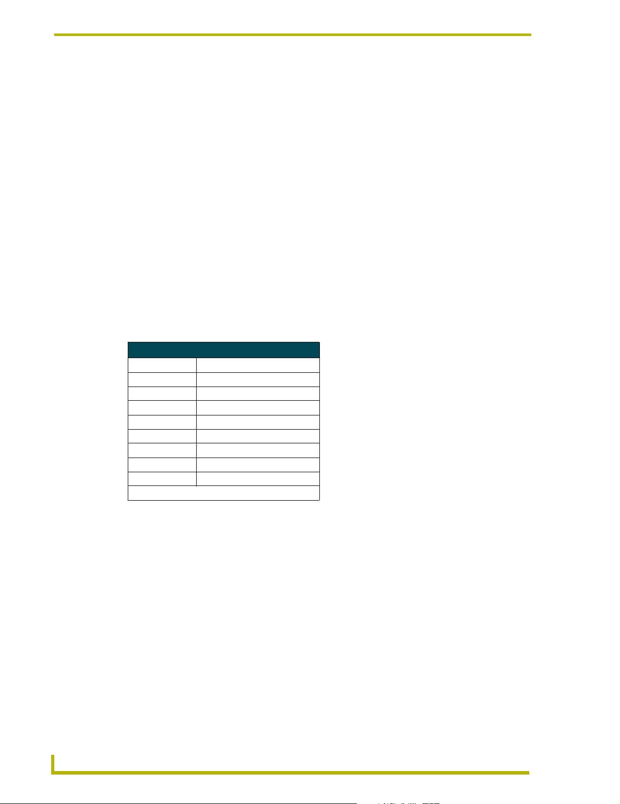
Specifications
Specifications
Dimensions (HWD) 4.68" x 2.93" x 1.72" (118.7 mm x 74.4 mm x 43.6 mm)
Voltage 12 VDC; 50 mA maximum per panel
Weight 3.17 oz (89.86 g)
Connector PROlink 4-pin data/power captive-wire
Front Panel Components:
Pushbuttons Up to 8 gray rubber pushbuttons in a 4 x 2 matrix
LEDs • One per button (8 total)
• 6 Channel indicators
• 6+ indicator (2nd pack indicator)
• P (Program mode) indicator
Overlay Custom engraved; default is blank.
Rear Panel Components:
DIP switch 8-position DIP switch that sets the panel's Preset Offset values, Pack Offsets,
Preset/Channel selection, and programming features.
PROlink LED Green PROlink status LED indicates PROlink power/data status as follows:
• One blink every two seconds indicates power is active and PROlink
communication is working.
• Full On indicates power is active and PROlink communication is not functioning
properly.
If the PROlink LED remains On, check the connections or refer to
the Troubleshooting section on page 12.
PROlink bus connector Connects to a Radia dimmer Pack using a PROlink cable.
Wiring 4-conductor, AWG #18 @1,000 feet (304.8 m) max. wire length
Color Availability White or black panel with gray pushbuttons
Mounting Options • Wall mount fits into most standard US wallboxes
• Podium mount
Product Information
PRO-DP8 Decor 8-Button Wall Panel
1
Page 7
Product Information
PRO-DP8 Overlay
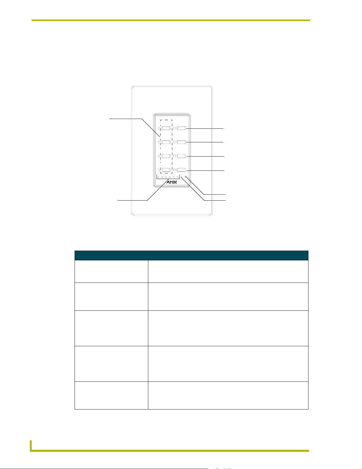
FIG. 1 shows a standard PRO-DP8 overlay. There are no numbers or labels screened on a standard
blank overlay. The buttons and LED labels are shown here to describe their orientation. Custom
engraved overlays are available on request.
Presets 1-4
SELECT
1
5
1
Select
2
6
2
3
7
3
Up arrow
Down arrow
4
8
OFF4
4123 566+P
Off
Additional channel (6+) LED
Channel LEDs (1-6)
Program (P) LED
FIG. 1 Standard PRO-DP8 overlay
The following table describes the pushbuttons and LEDs and their associated functions:
PRO-DP8 Pushbuttons and LEDs
Pushbuttons (1-8):
1-4 (Presets buttons) Once the panel has been programmed, press these buttons to recall pro-
grammed presets.
5 (Select) Press to choose from available channels (1-12 or 7-18), depending on the
setting of DIP switches 4 and 5.
See the Using Switches 4 and 5 to Specify Which Pack(s) to
Control section on page 16 for details.
6 (Up) Ramps up the light level and Presets for the selected channel, or recalls
7 (Down) Ramps down the light level and Presets for the selected channel, or recalls
8 (Off) Turns off a selected preset. The off button can be offset via the DIP for sys-
Preset 6, depending on the setting of DIP switch 7.
See the Using Switch 7 to Enable Either Preset Recall mode, or Zone
Select/Preset Ramping section on page 18 for details.
Press the Up and Down arrows simultaneously to enter Program mode.
Preset 6, depending on the setting of DIP switch 7.
See the Using Switch 7 to Enable Either Preset Recall mode, or Zone
Select/Preset Ramping section on page 18 for details.
Press the Up and Down arrows simultaneously to enter Program mode.
tems with multiple panels.
See the Using Switch 6 to Offset the Off Button (Pushbutton 8) section on
page 17 for more information.
2
PRO-DP8 Decor 8-Button Wall Panel
Page 8
Product Information
PRO-DP8 Pushbuttons and LEDs (Cont.)
LEDs:
Channel LEDs (1-6) Shows the channel (1-6, 7-18, or 13-18) that is currently selected, depend-
Program (P) LED Lights when the panel is Program mode, allowing you to program presets.
Additional channel (6+) LED Lights to indicate that a channel higher than 6 is selected (this LED works
ing on the DIP switch offset setting. See the Using Switches 1, 2 and 3 to
Set Button Offset Values section on page 16 for more information.
To enter Program mode, press the up and down arrow buttons (6 and 7)
simultaneously until the PGM LED lights.
in conjunction with LEDs 1 through 6).
For example, if channel 8 was selected, then LED 2 and 6+ would light
simultaneously, depending on the DIP switch offset setting. See the Using
Switches 1, 2 and 3 to Set Button Offset Values section on page 16 for
more information.
The first time PROlink is wired to a PRO-DP8 panel, each LED on the panel lights in sequence,
starting with LED 1 and ending with the 6+ LED. Recycling power to the panel resets the
PRO-DP8 to its default setting (Channel 1 LED lights and is active).
Presets, Channels and Zones
A Preset is a set of instructions used for the recall of a stored scene (a group of lighting levels). A
group of lighting levels is also known as a zone. The PRO-DP8 uses channels to control zones.
Each channel represents a controlled lighting zone. Preset fade time is the amount of time it takes to
fade from one Preset light level to the next. A zone's light level is the intensity of light produced
between the On/Off states.
When a Preset is selected, the active zone/channel moves to the specific light level stored in
memory for that Preset. Lights associated with a particular zone/channel fade from one Preset to the
next based on the length of time that you have selected for the fade intervals, in one second
intervals (default = 3 seconds). The PRO-DP8 can select and change PRESETS 1 through 4 and
Off.
A PRO-DP8 has a specific value associated to each Preset button on the panel. For installations
where multiple PRO-DP8 panels are used to share control of a single Pack, you can set identical
Presets on more than one panel. Multiple panels that share all or some of the same presets can be
used to perform identical functions on a particular pack.
For installations with multiple panels controlling multiple Packs, there can't be any overlapping in
Preset assignments; therefore, by offsetting the values for the individual buttons on different panels
(via the rear-panel DIP switch), it is possible to have multiple PRO-DP8 panels in a Radia Lighting
system, without conflicts.
! For more information on setting offset values to the panel pushbuttons, refer to the Using
Switches 1, 2 and 3 to Set Button Offset Values section on page 16.
PRO-DP8 Decor 8-Button Wall Panel
3
Page 9
Product Information
Packs
Packs refer to the Dimmer Control Cards (such as the RDD-DM4/DM6) and/or Integrated Dimmer
Modules (such as the RDC-DC/PDC). Each LED on the PRO-DP8 zone/channel LED indicator
represents one lighting channel/zone.
The PRO-DP8 controls up to 3 Packs; each individual Pack housing up to 6 lighting channels. Each
Pack is connected to the PRO-DP8 via PROlink cable. The PROlink cable provides power to the
PRO-DP8 panel, and communication between the panel and pack(s).
DIP switch positions 4 and 5 (on the rear panel DIP switch) determine which Pack(s) are being
controlled by each PRO-DP8 panel. Configure these switches to control either Pack 1, Pack 2, or
combinations of Packs 1 and 2, or Packs 2 and 3.
! For information on configuring the DIP switch for multiple Pack assignments, refer to the
Using Switches 4 and 5 to Specify Which Pack(s) to Control section on page 16.
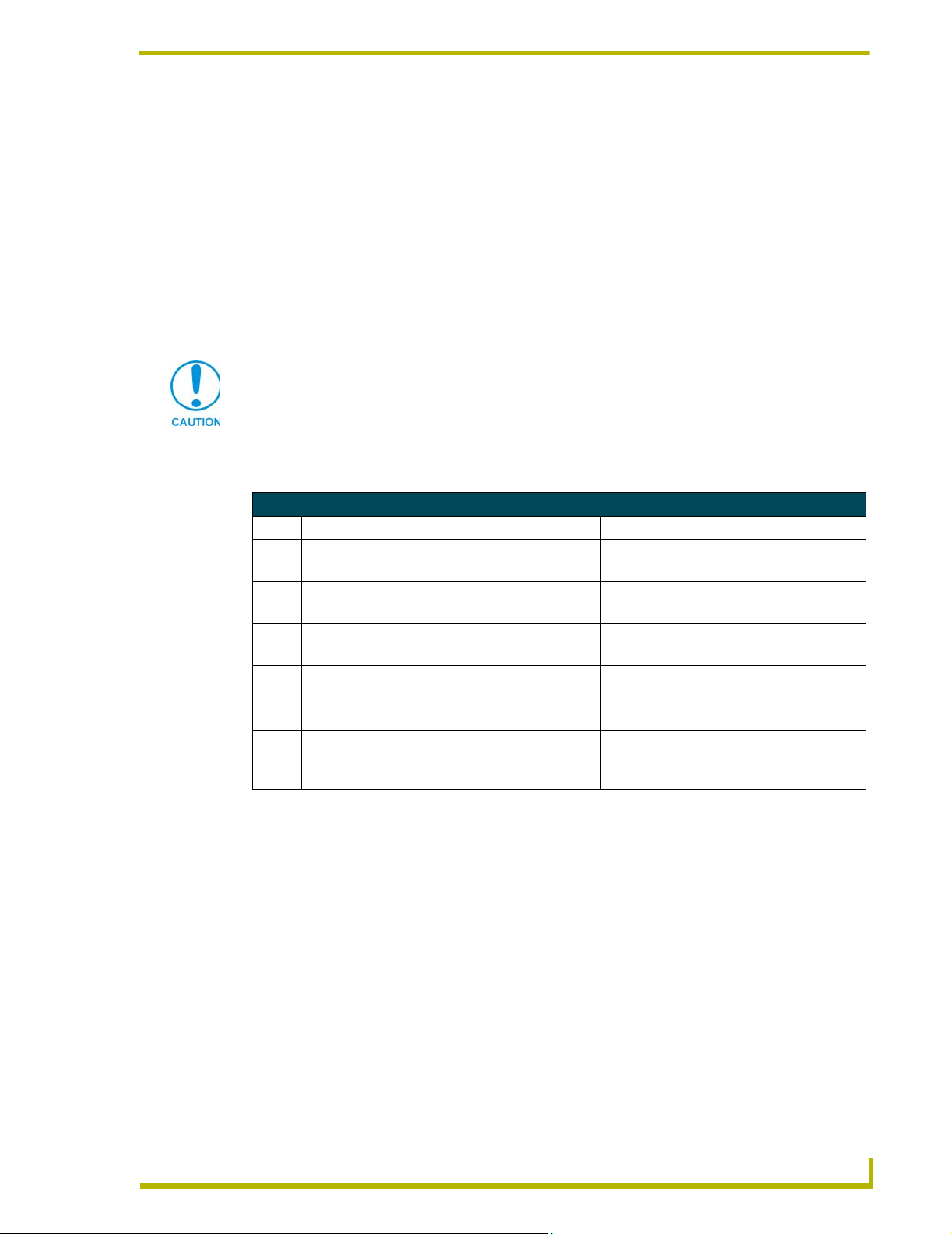
Default presets on the dimmer packs
Radia Dimmer Cards and Integrated Dimmer Control Cards (Packs) have 8 contact closures, pre-
programmed with default presets. By default, the dimmer packs ship with the following presets for
each contact closure:
Dry Closure Default Presets
Contact Closure Default Function
1 Channel 1 at 100% in 1 second*
2 Channel 2 at 100% in 1 second*
3 Channel 3 at 100% in 1 second*
4 Channel 4 at 100% in 1 second*
5 Channel 5 at 100% in 1 second*
6 Channel 6 at 100% in 1 second*
7 Pack on (channels 1-6)*
8 Pack on (channels 1-6)*
*All other channels are undefined
4
PRO-DP8 Decor 8-Button Wall Panel
Page 10

Product Information
Sample Product Application
You can use the PRO-DP8 with Radia Dimmer Packs to control lighting zones. The PRO-DP8 can
control up to three Packs. FIG. 2 shows an equipment configuration model using multiple PRO-
DP8 panels with a PROlink connection to two dimmer control cards.
Controlled
lighting
PROlink cable
Controlled
lighting
Radia dimmer (Pack 1) Radia dimmer (Pack 2)
PROlink bus connector
PROlink cable
PRO-DP8 PRO-DP8 PRO-DP8 PRO-DP8
FIG. 2 Sample application
PRO-DP8 Decor 8-Button Wall Panel
5
Page 11

Product Information
6
PRO-DP8 Decor 8-Button Wall Panel
Page 12

Wiring and Installation
Preparing the PRO-DP8 and Dimmer Control Cards
Assigning Pack numbers on the dimmer control cards
Each dimmer card in the system must have its own unique PROlink device number, or Pack
number. The Pack number is assigned via the PROLink DIP switch (SW2) on the dimmer control
cards:
1. Turn Off the breaker on the dimmer control card.
2. Set the Pack number assignment on the individual dimmer control card via the PROlink
Address DIP switch (SW2).
The Pack number is determined by the value of all the switch position settings. The Pack
number assignment range is 1-10. The lighting system will not work if you assign Pack
numbers outside of this range.
The following table shows the PROlink DIP switch positions and their values:
Wiring and Installation
Position1234 5 6 7 8
Value 1248N/AN/AN/ATest
Set the first enclosure to a Pack value 1 by switching the PROlink DIP switch 1 to On and the
second enclosure to either a Pack value of 2 (by switching DIP switch 2 to On), or a Pack value
of 3 (by switching the DIP switches 1 and 2 to On) for a two-enclosure system.
3. Turn the PRO-DP8 face down and verify that all DIP switches are in the Off position (factory
default).
4. Connect a 4-pin PROlink cable to the PROlink bus connector to the rear panel of the
PRO-DP8.
5. Power On the dimmer control card.
6. Press the Reset button on the dimmer control card.
7. Verify the PRO-DP8 is communicating with the dimmer control card by watching the
sequential lighting of each LED on the front panel of the PRO-DP8, and the one-blink action of
the PROlink LED (rear panel).
DIP switch #8 is a test switch. It will turn all the lights to full in the On position. It must
be in the Off position for normal operation.
Assigning Pack numbers (1-3) on the panel
Once each dimmer Pack has a unique device number, you must assign the Packs to the desired
pushbuttons on the PRO-DP8 panel:
1. Note the Pack value assigned on the dimmer control card (see previous steps).
2. Unplug the 4-pin PROlink cable from the rear bus connector of the PRO-DP8.
PRO-DP8 Decor 8-Button Wall Panel
7
Page 13

Wiring and Installation
3. Change DIP switches 4 and 5 to match those values listed in the following table for the number
DIP Switch Settings for 1, 2 or 3 Packs
DIP Switch 4 DIP Switch 5 Pack 1-3 Result
4. Reconnect the PROlink cable to the PROlink bus connector located at the rear of the
Wiring the PRO-DP8
The PRO-DP8 uses a 4-pin PROlink connector for power and data, located on the back of the panel.
PROlink wiring guidelines
of desired Packs (1-3).
OFF OFF Pack 1 ONLY Channels 1-6 (Pack 1)
ON OFF Packs 1 & 2 Channels 1-12 (Packs 1 and 2)
OFF ON Pack 2 ONLY Channels 7-12 (Pack 2)
ON ON Packs 2 & 3 Channels 7-18 (Packs 2 and 3)
PRO-DP8.
! Use 24-gauge twisted-pair cable for runs of 300 feet (91.44 meters) and under.
! Use 22-gauge shielded low-capacitance cable for runs of up to 1,000 feet (304.8 meters).
! Additional panels can be daisy-chained or connected directly to the Pack's terminal.
! Avoid connecting more than three PRO-D:P:S to a Pack without a separate power supply
for the panels (see the Using a PROlink 4-pin connector with an external 12 VDC power
supply section on page 9 for details).
Preparing captive wires
You will need a wire stripper, and flat-blade screwdriver to prepare and connect the captive wires.
1. Strip 0.25 inch (6.35 mm) of wire insulation off all wires.
2. Insert each wire into the appropriate opening on the connector according to the wiring
diagrams and connector types described in this section.
3. Turn the flat-head screws clockwise to secure the wires in the connector. Do not over-torque
the screws; doing so can bend the seating pins and damage the connector.
Using a PROlink 4-pin connector for data and power
These steps describe how to connect the dimmer Pack's PROlink connector to the PROlink
connector (male) on the rear panel of the PRO-DP8 for data and 12 VDC power.
Check for short circuits and continuity before connecting panels to the PROlink
connector on the dimmer Pack.
1. The captive-wire terminal on the PRO-DP8 is wired to an orange captive-wire terminal on the
Pack. Insert each wire into the appropriate opening on the connector, according to the wiring
diagram shown in FIG. 1.
8
PRO-DP8 Decor 8-Button Wall Panel
Page 14

Wiring and Installation
PRO-DP8
+12
PR+
PR-
GND
FIG. 1 Wiring diagram for connecting the PRO-DP8 to a single dimmer control card
Pack 2Pack 1
+12
PR+
PRGND
Additional panels can be daisy-chained or connected directly to the Pack's terminal. Use a
12 VDC power supply when more than three PRO-DP8 panels are used with one Pack. Refer to
the Using a PROlink 4-pin connector with an external 12 VDC power supply section on page 9
for more information.
Verify PROlink wiring connections are correct before applying power to the Pack.
2. Connect the PROlink connector to the panel (see the Preparing captive wires section on
page 8).
3. Locate the green PROlink LED on the rear side of the panel. If the green LED flashes once
every 2 seconds, the panel is communicating properly with the Pack. If the LED is on and not
flashing, disconnect the PROlink connector and recheck all PROlink connections; reconnect
the PROlink connector to the panel and verify the LED is flashing once every 2 seconds.
4. Test to see if the panel recalls a Preset or ramps dimmers (if test fails, refer to
the Troubleshooting section on page 12).
Using a PROlink 4-pin connector with an external 12 VDC power supply
Use a 12 VDC power supply when the distance between the Pack and PRO-DP8 exceeds 1,000 feet
(304.8 m), or when more than three PRO-DP8 panels are used with one Pack. Make sure to connect
only the GND wire on the PROlink connector when using a 12 VDC power supply.
While AMX recommends installing a maximum of three PRO-DP8 panels per Pack,
the actual maximum number of panels allowed per Pack is a function of power and
distance between the two.
Connect the Pack's PROlink connector to the PROlink connector on the rear panel of the PRO-DP8,
as described in the following steps.
1. The captive-wire terminal on PRO-DP8 is wired to an orange captive-wire terminal on the
Pack. Insert each wire into the appropriate opening on the connector, according to the wiring
diagram shown in FIG. 2.
PRO-DP8 Decor 8-Button Wall Panel
9
Page 15

Wiring and Installation
12 VDC power supply
PWR (+)
GND (-)
PRO-DP8
+12
PR+
PR-
GND
FIG. 2 PROlink wiring diagram using an external 12 VDC power supply
Do not connect the PWR wire to the PROlink connector’s PWR (+) terminal on the
control system side of the connector.
Pack 1
Pack 2
+12
PR+
PR-
GND
2. Connect the PROlink connector to the panel (see the Preparing captive wires section on
page 8).
3. Check PROlink LED on the rear side of the panel. If the green LED flashes once every 2
seconds, the panel is communicating properly with the Pack. If the LED is on and not flashing,
disconnect the PROlink connector and recheck all PROlink connections; reconnect the
PROlink connector to the panel and verify the LED is flashing once every 2 seconds.
PROlink status LED
The green LED on the rear panel of the PRO-DP8 is the PROlink status LED. This LED indicates
the communication status of the panel on the PROlink bus:
! Flashing (once every 2 seconds) indicates that PROlink communications are working
properly.
10
! Full-on indicates that the panel is not communicating with the PROlink bus. Check the
PROlink wiring to the Pack and to any other panels. Refer to the Troubleshooting section
on page 12 for details.
Testing
The following steps describe how to test the PRO-DP8 to verify it is working properly:
1. Disconnect power from the PRO-DP8.
2. Reconnect the power supply to the panel. Check for a blinking green LED on back of the
PRO-DP8 panel to verify proper operation.
3. Press Presets 1-10 (default) to cycle through Preset lighting levels.
4. Press Off to turn lights off.
If this test fails, refer to the Troubleshooting section on page 12.
PRO-DP8 Decor 8-Button Wall Panel
Page 16
Wiring and Installation
Phasing
If you experience erratic ramping with your lights, it is possible that the dimmer control card could
be wired out of phase. Check and correct power wiring and repeat the Preset test steps (see
Testing).
If the green PROlink status LED stays on, or nothing happens when the Presets are selected, check
the Pack number value on the dimmer control card. Set the dimmer control cards to different Pack
numbers by using the PROlink DIP switch (SW2) to set the Pack number. Refer to the Assigning
Pack numbers on the dimmer control cards section on page 7 for details.
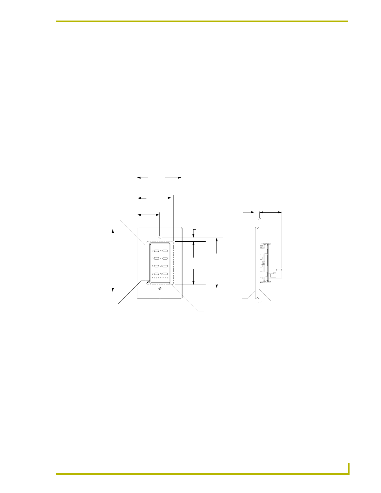
Mounting Procedures
FIG. 3 shows the podium mounting dimensions for the PRO-DP8. AMX recommends mounting the
PRO-DP8 in a standard one-gang wallbox with a minimum internal clearance of 2-5/8" x 1-3/4" x
1-5/8" (HWD).
2.93"
(74.4 mm)
REF
1.80"
(22.86 mm)
Cutout
0.90"
(45.72 mm)
.
240" (6.09 mm)
.30"
(7.7 mm)
From surface
1.42"
(36.1 mm)
Max.
Depth
4.68"
118.87 mm)
.125 R
(3.175 mm)
(Max.)
FIG. 3 PRO-DP8 podium mounting dimensions
Install unit using
supplied #6-32
machine screws
at these locations
2.80"
(71.12 mm)
3.281"
(83.34 mm)
Wallplate
Mounting bezel
Bezel
1. Use the cutout dimension shown in FIG. 3 to cutout the install surface for the PRO-DP8.
2. Confirm that the terminal end of the PROlink cable is disconnected, and not receiving power.
3. Gently remove the bezel from the wallplate.
4. Plug in the panel.
5. Place the panel in the wallbox; align the screw holes with the mounting holes on the panel.
Fasten the panel to the wallbox using the screws supplied.
6. Install the overlay.
7. Snap the wallplate back on the bezel.
PRO-DP8 Decor 8-Button Wall Panel
11
Page 17

Wiring and Installation
Troubleshooting
The following table gives solutions to the most common installation problems.
Solutions to Common Installation Problems
Problem Resolution
Presets fade erratically. Check phasing.
Panel LED stays on. Check the PROlink wiring, Pack number, and dimmer
Cannot select zones 1 - 12. Check Pack number and mode settings.
No operation. Check PROlink wiring.
All lights stay On. Check dimmer DIP switch settings and disconnect/
In the Preset Recall Mode, Presets can be recalled,
but Up and Down arrows do not work.
Pack settings.
reconnect AXlink or RS232 control.
Check Pack numbers. Verify that Packs are set for 1
and 2
12
PRO-DP8 Decor 8-Button Wall Panel
Page 18

Wiring and Installation
Sample Wiring Diagram
FIG. 4 shows a sample equipment wiring diagram using two Radia Lighting Dimmers and three
PRO-DP8 wall panels. This illustration shows the two packs wired to two 120 VAC single-phase
20A breakers.
120 VAC 1 20A
breaker A
pack 1
PROlink connector
(orange)
120 VAC 1 20A
breaker A
A
B
C
A
B
C
neutral
neutral
Circuit Breaker Panel
pack 2
FIG. 4 Sample equipment wiring diagram using two Radia dimmer packs
PRO-DP8 Decor 8-Button Wall Panel
PROlink cable
SELECT1
2
3
OFF4
4123 566+P
1 23 5466+ P
PROlink connector
(orange)
SELECT
1
2
3
4
OFF
1
2
3
4
1 23 5466+ P
SELECT
OFF
PRO-DP8s
1
2
3
4
1 23 5466+ P
SELECT
OFF
13
Page 19

Wiring and Installation
14
PRO-DP8 Decor 8-Button Wall Panel
Page 20
DIP Switch Configuration
This section describes the functionality associated with the various DIP switch settings available on
the PRO-DP8 panel. These switches determine the front panel functions and should not be thought
of as user accessible.
DIP Switch Functions (1-8)
The panel functions are set by the configuration of the DIP switch, located on the back of PRO-DP8
panel. The factory default is for all the switches to be in the Off position.
Always disconnect the PROlink cable from the PRO-DP8 to remove power before
changing DIP switch settings. Once the switche(s) are set, reconnect the PROlink
cable to the PRO-DP8 to provide power to the panel.
On power-up, the pushbutton LEDs momentarily light in sequence until the Channel 1
LED remains on.
The following table lists the operational assignments for the PRO-DP8 DIP switch.
DIP Switch Assignments
Switch On Function Off Function (factory default)
1Bit 1 Preset Offset. Offsets panel pushbuttons by 4.
With this offset, the pushbuttons = 5-20.
2Bit 2 Preset Offset. Offsets panel pushbuttons by 8.
With this offset, the pushbuttons = 9-24.
3Bit 3 Preset Offset. Offsets panel pushbuttons by 16.
With this offset, the pushbuttons = 17-32.
4 Can select zones on 2 packs (12 zones). Can select zones on 1 pack (6 zones).
5 Select zones starting with pack 1 (zone 1). Select zones starting with pack 2 (zone 7).
6 Preset 64+ Offset Preset 8+ Offset
7 Recall Presets only (on pushbuttons 1-8) Enables Zone Select function on pushbutton 5,
8 Program/record disable Program/record enable.
DIP Switch Configuration
No offset (pushbuttons = 1-8)
No offset (pushbuttons = 1-8)
No offset (pushbuttons = 1-8)
and up/down ramping on pushbuttons 6 and 7.
PRO-DP8 Decor 8-Button Wall Panel
15
Page 21
DIP Switch Configuration
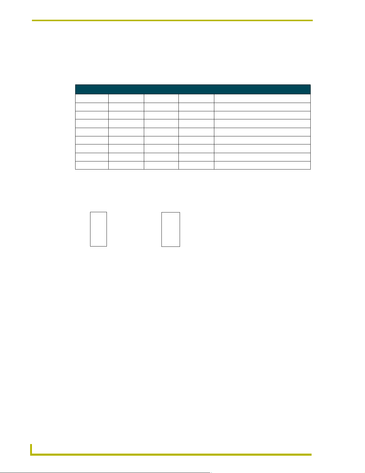
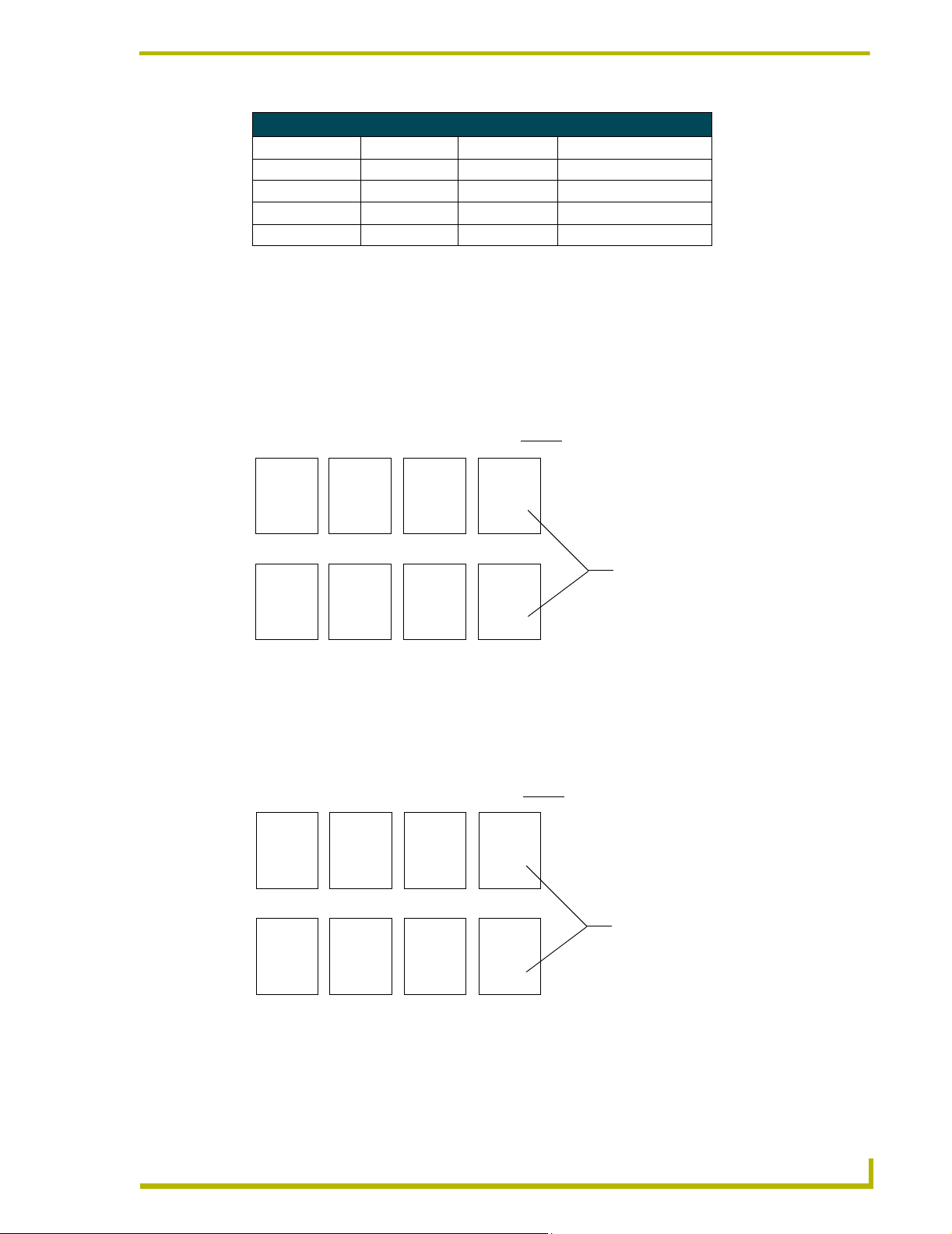
Using Switches 1, 2 and 3 to Set Button Offset Values
The default setting for the DIP switch is all off. Thus, by default, there is no offset assigned to the
panel pushbuttons (1-8). Use DIP switches 1-3 to set offsets by factors of four, as shown in the
following table.
Preset Offsets Chart (for DIP Switches 1, 2, and 3)
Preset Offset DIP switch 1 DIP switch 2 DIP switch 3 Result
FIG. 1 is an example of how the Preset Offset can be used to change the value associated with a
Preset.
0 Off Off Off Pushbuttons = 1-8 (no offset - default)
4 On Off Off Pushbuttons = 5-12
8 Off On Off Pushbuttons = 9-16
12 On On Off Pushbuttons = 13-20
16 Off Off On Pushbuttons = 17-24
32 On Off On Pushbuttons = 33-40
48 Off On On Pushbuttons = 49-56
64 On On On Pushbuttons = 65-72
DIP switches 1 - 8 Off
15
26
37
4 8
FIG. 1 Sample DIP switch Preset Offset
DIP switch 2 On, all others Off
913
10 14
11 15
12
Preset values are now offset by 8
16
Using Switches 4 and 5 to Specify Which Pack(s) to Control
Switches 4 and 5 on the PROlink DIP switch (SW2, located on the dimmer control/Integrated
Dimmer Modules) determine which pack the PRO-DP8 communicates with. The PRO-DP8
controls up to three Packs, consisting of either Dimmer Control Cards and/or Integrated Dimmer
Modules, within a Radia Lighting system. These Pack numbers can correspond to an Integrated
Dimmer Module (like the RDD-DM4 or RDD-DM6) that is connected to the PRO-DP8 via a
PROlink cable that provides both power and communication between the two devices.
These switches allow for the selection of six or 12 channels. To access two available dimmer Packs,
you must set the PROlink DIP switches on each of the dimmer Packs to different values. The
PRO-DP8 can connect to dimmer Packs 1, 2, and 3. Set the PROlink Pack numbers that are
controlled by the individual PRO-DP8s by changing the position of DIP switches 4 and 5 to the
values indicated in the following table.
16
PRO-DP8 Decor 8-Button Wall Panel
Page 22
DIP Switch Configuration
Pack Offsets for DIP Switches 4, 5, and Associated Channels
Preset Offset DIP switch 4 DIP switch 5 Channels
Pack 1 ONLY OFF OFF 1 - 6
Packs 1 & 2 ON OFF 1 - 12
Pack 2 ONLY OFF ON 7 - 12
Packs 2 & 3 ON ON 7 - 18
Using Switch 6 to Offset the Off Button (Pushbutton 8)
In multi-panel installations, you must offset the Off button (pushbutton 8), so that pressing Off on
the panel doesn’t turn off other panels on the PROlink bus.
! If DIP switch 6 is Off and the offset is zero (DIP switches 1-3 Off), recall Preset value is
8. Use FIG. 2 to determine the recall Presets associated with various Presets when DIP
switch 6 is Off.
+0 +4 +8 +12
1 5
2 6
3 7
4 8
+16 +32 +48 +64
17 21
18 22
19 23
20 24
FIG. 2 DIP switch 6 Offsets in the On position
5 9
6 10
7 11
8 12
33 37
34 38
35 39
36 40
! If DIP switch 6 is On, and the offset is zero (DIP switches 1-3 Off), recall Preset is 81.
9 13
10 14
11 15
12 16
49 53
50 54
51 55
52 56
13 17
14 18
15 19
16 20
65 69
66 70
67 71
68 72
Preset Offset value used for button 8 (OFF). This
value is determined by setting DIP switches 1-3
Recall Preset value associated for button 8
(OFF) for the related Preset Offset value
Use FIG. 3 to determine the recall Presets associated with various Presets when DIP
switch 6 is On.
+0 +4 +8 +12
1 5
2 6
3 7
4 81
5 9
6 10
7 11
8 82
9 13
10 14
11 15
12 83
13 17
14 18
15 19
16 84
Preset Offset value used for button 8 (OFF). This
value is determined by setting DIP switches 1-3
+16 +32 +48 +64
17 21
18 22
19 23
20 85
FIG. 3 DIP switch 6 Offsets at the On position
PRO-DP8 Decor 8-Button Wall Panel
33 37
34 38
35 39
36 86
49 53
50 54
51 55
52 87
65 69
66 70
67 71
68 88
Recall Preset value associated for button 8
(OFF) for the related Preset Offset value
17
Page 23

DIP Switch Configuration
Using Switch 7 to Enable Either Preset Recall mode, or Zone Select/Preset Ramping
Panel pushbutton 5 (Select buttons) has two possible functions, depending on the setting of DIP
switch 7. DIP switch 7 enables/disables the panel’s ability to select zones, or recall presets.
Using Switch 8 to Enable/Disable Program Mode
DIP switch 8 determines if the panel has the ability to enter Program mode, which allows you to
program lighting scenes, and store them as programmed Presets.
! Set switch 7 to Off (factory default setting) to enable Zone Select mode, and allow
ramping of light levels. In this mode, pushbuttons 6 and 7 function as Up and Down
buttons for ramping a selected preset.
! Set switch 7 to On to disable preset ramping. In this mode, pushbuttons 6 and 7 recall
Presets instead of ramping presets.
! Set switch 8 to Off (factory default setting) to enable programming of preset levels and
fade times.
When preset programming is enabled, press pushbuttons 6 and 7 simultaneously to enter
Program Mode. The P (Program) LED lights when this mode is active.
! Set switch 8 to On to disable the programming function. When Program mode is
disabled, panel pushbuttons 6 and 7 do not allow the panel to enter Program mode.
18
PRO-DP8 Decor 8-Button Wall Panel
Page 24

Panel Programming/Operation
Program Mode
The panel must be in Program mode in order to do any programming. To enter Program mode, DIP
switch 8 must be set to Off (its default setting).
To enter Program mode, press the Up and Down buttons (pushbuttons 6 and 7) simultaneously for 2
seconds. The P LED on the front of the panel lights to indicate that Program mode is active.
If you make a mistake, or decide not to record changes, press the Up/Down buttons again to cancel
Program mode.
Programming Presets
The number of Presets available to program depends on the setting of DIP switch 7.
If DIP switch 7 is set to Off (Default mode), pushbuttons 1-4 are available as Preset buttons, and
pushbuttons 5-8 are used for other panel functions (i.e. Select, Up/Down, and Off.
If DIP switch 7 is set to On (Preset Recall mode), all pushbuttons (1-8) are available as Preset
buttons. Refer to the DIP Switch Configuration section on page 15 for details.
Panel Programming/Operation
1. Ramp all active channels to 0 using the Select (pushbutton 5) and Up/Down buttons
(pushbuttons 6 and 7). Alternatively, you can use the Off button to turn all lights off.
2. Use the Select button to select a zone and then use the Up/Down buttons to ramp the light to
the desired level. Repeat this for all zones to set all lights to the desired level.
3. Enter Program mode by pressing the Up and Down buttons simultaneously for 2 seconds
(Program mode is indicated by the P LED).
4. Press the Preset button where the new preset will be stored. The length of time that you hold
the button down determines the ramp speed.
5. Repeat the preceding steps as required for other Presets.
Programming Ramping Presets
1. To enter Ramping Preset mode, press and hold the desired Preset button for 2 seconds.
Ramping Preset mode is indicated by the Up/Down button LEDs (lit simultaneously).
2. Press the Up and Down buttons (pushbuttons 6 and 7) to ramp the light level for the selected
Preset as needed.
3. Release the Preset button to stop ramping. Preset Ramping mode quits after 6 seconds.
4. Repeat the preceding steps as required for other Presets.
PRO-DP8 Decor 8-Button Wall Panel
19
Page 25

Panel Programming/Operation
Setting and changing fade times
1. Press the Preset button where the new ramp time will be stored.
2. Enter Program mode (indicated by the P LED).
3. Set the fade time by pressing and holding a Preset button for the amount of time you want the
fade to occur (the fade is from a currently active Preset level to the next active level). The new
fade time is recorded when the button is released.
4. Wait 8 seconds for the new fade setting to be associated with the Preset (do not touch any
buttons at this time).
5. Repeat the preceding steps as required for other Presets.
Panel Operation
The following sub-sections describe using the panel to recall, adjust, and ramp programmed
presets. These instructions assume that the panel has already been programmed.
Recalling a programmed Preset
To recall a programmed Preset, simply press the Preset button associated with the Preset. The LED
next to the selected button lights to indicate the active Preset.
! If the panel is in Preset Recall mode (DIP switch 7 set to On), any pushbutton (1-8) can
recall a Preset.
! If the panel is in Default mode (DIP switch 7 set to Off), pushbuttons 1-4 can recall
Presets. In Default mode, the Select (pushbutton 5), and Up/Down (pushbuttons 6 and 7)
buttons do not recall Presets, and Off (pushbutton 8) recalls the Off Preset.
Ramping Presets
Ramping a Preset involves either raising or lowering a light level on an active Preset. DIP switch 7
determines if the panel has the ability to raise or lower channel levels.
! If switch 7 is in default mode (Off), pushbuttons 6 and 7 function as Up and Down
buttons for ramping presets.
! If switch 7 is On, channel ramping is disabled, and pushbuttons 5 through 7 recall Presets
(instead of selecting or ramping channels).
To raise and lower the light level for Preset in a selected zone (0-100%):
1. Press Select until the desired channel/zone LED is active (indicated by the channel LED).
For systems with more than 6 channels, the Select button cycles through all on-line channels,
and the 6+ LED indicates when you have selected a channel above channel 6. For example, if
you cycled through the channels (via the Select button), channel 8 would be represented by
LED 2 on, and the 6+ LED lit simultaneously.
20
2. Press and hold the Preset for approximately 2 seconds to activate the desired lighting level that
you want to ramp.
3. Press the Up/Down buttons (pushbuttons 6 and 7) to raise or lower the light level for the
selected channel/zone.
4. Continue selecting zones and repeat steps 1 through 3 as many times as needed.
PRO-DP8 Decor 8-Button Wall Panel
Page 26

Panel Programming/Operation
RO-DP8 Decor 8-Button Wall Panel
21
Page 27

AMX reserves the right to alter specifications without notice at any time.
ARGENTI NA • AUST RALIA • BELGIUM • BRAZIL • CANADA • CHINA • ENGLAN D • FRANC E • GERMA NY • GRE ECE • HO NG KONG • INDIA • I NDONES IA • ITALY • JAPAN
LEBANON • MALAYSIA • MEXICO • NETHERLANDS • NEW ZEALAND • PHILIPPINES • PORTUGAL • RUSSIA • SINGAPORE • SPAIN • SWITZERLAND • THAILAND • TURKEY • USA
ATLANTA • BOSTON • CHICAGO • CLEVELAND • DAL LAS • DENVER • INDIANAPOLIS • LOS ANGELES • MINNEAPOLIS • PHILADELPHIA • PHOENIX • PORTLAND • SPOKANE • TAMPA
3000 RESEARCH DRIVE, RICHARDSON, TX 75082 USA • 800.222.0193 • 469.624.8000 • 469-624-7153 fax • 800.932.6993 technical support • www.amx.com
2004 AMX Corporation. All rights reserved. AMX, the AMX logo, the building icon, th e home icon, and the light bulb icon are all trademarks of AMX Corporation.
©
043-004-1006 1/04
*In Canada doing business as Panja Inc.
 Loading...