

Page 1
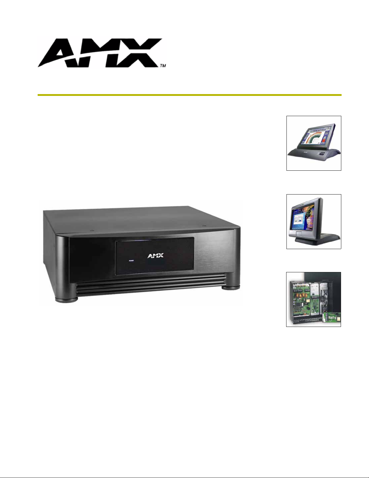
PLB-AS16
16 x 16 Stereo Audio Switcher
instruction manual
Landmark Products
Page 2

AMX Limited Warranty and Disclaimer
AMX Corporation warrants its products to be free of defects in material and workmanship under normal use for three
(3) years from the date of purchase from AMX Corporation, with the following exceptions:
• Electroluminescent and LCD Control Panels are warranted for three (3) years, except for the display and touch
overlay components that are warranted for a period of one (1) year.
• Disk drive mechanisms, pan/tilt heads, power supplies, and MX Series products are warranted for a period of one
(1) year.
• AMX Lighting products are guaranteed to switch on and off any load that is properly connected to our lighting
products, as long as the AMX Lighting products are under warranty. AMX Corporation does guarantee the
control of dimmable loads that are properly connected to our lighting products. The dimming performance or
quality cannot be guaranteed due to the random combinations of dimmers, lamps and ballasts or transformers.
• Unless otherwise specified, OEM and custom products are warranted for a period of one (1) year.
• AMX Software is warranted for a period of ninety (90) days.
• Batteries and incandescent lamps are not covered under the warranty.
This warranty extends only to products purchased directly from AMX Corporation or an Authorized AMX Dealer.
All products returned to AMX require a Return Material Authorization (RMA) number. The RMA number is
obtained from the AMX RMA Department. The RMA number must be clearly marked on the outside of each box.
The RMA is valid for a 30-day period. After the 30-day period the RMA will be cancelled. Any shipments received
not consistent with the RMA, or after the RMA is cancelled, will be refused. AMX is not responsible for products
returned without a valid RMA number.
AMX Corporation is not liable for any damages caused by its products or for the failure of its products to perform.
This includes any lost profits, lost savings, incidental damages, or consequential damages. AMX Corporation is not
liable for any claim made by a third party or by an AMX Dealer for a third party.
This limitation of liability applies whether damages are sought, or a claim is made, under this warranty or as a tort
claim (including negligence and strict product liability), a contract claim, or any other claim. This limitation of
liability cannot be waived or amended by any person. This limitation of liability will be effective even if AMX Corpo-
ration or an authorized representative of AMX Corporation has been advised of the possibility of any such damages.
This limitation of liability, however, will not apply to claims for personal injury.
Some states do not allow a limitation of how long an implied warranty last. Some states do not allow the limitation or
exclusion of incidental or consequential damages for consumer products. In such states, the limitation or exclusion of
the Limited Warranty may not apply. This Limited Warranty gives the owner specific legal rights. The owner may
also have other rights that vary from state to state. The owner is advised to consult applicable state laws for full
determination of rights.
EXCEPT AS EXPRESSLY SET FORTH IN THIS WARRANTY, AMX CORPORATION MAKES NO
OTHER WARRANTIES, EXPRESSED OR IMPLIED, INCLUDING ANY IMPLIED WARRANTIES OF
MERCHANTABILITY OR FITNESS FOR A PARTICULAR PURPOSE. AMX CORPORATION
EXPRESSLY DISCLAIMS ALL WARRANTIES NOT STATED IN THIS LIMITED WARRANTY. ANY
IMPLIED WARRANTIES THAT MAY BE IMPOSED BY LAW ARE LIMITED TO THE TERMS OF THIS
LIMITED WARRANTY.
Page 3
Safety Instructions
Safety Instructions
There are no user-serviceable parts inside the PLB-AS16. Opening the PLB-AS16
may void your warranty and expose you to dangerous voltages.
1. Read Instructions - Read all of the safety and operating instructions before operating the
product.
2. Retain Instructions - Retain the safety and operating instructions for future reference.
3. Heed Warnings - Adhere to all warnings on the product and in the operating instructions.
4. Follow Instructions - Follow all operating and use instructions.
5. Cleaning - Unplug this product from the wall outlet or other power source before cleaning. Do
not use liquid or aerosol cleaners. Use only a clean, damp cloth for cleaning.
6. Attachments - Do not use attachments or accessories that are not recommended by the
manufacturer, as they may cause hazards.
7. Water and Moisture - Do not use this product near water, such as a bath tub, wash basin,
kitchen sink, wet basement, swimming pool, or any other water or wet area.
8. Accessories - Do not place this product on an unstable cart, stand, tripod, bracket, table, or
other surface or object. The product may fall, causing serious bodily injury to a child or adult.
It may also cause equipment damage. Use this product only with a cart, stand, tripod, bracket,
table, or other device that is recommended by the manufacturer or sold with the product.
Mount this device only in accordance with the manufacturer's instructions, using only
mounting accessories recommended by the manufacturer.
LB-AS16 16 x 16 Stereo Audio Switcher
a
Page 4

Safety Instructions
9. Moving the Product - A product and cart combination must be moved with care. Quick stops,
excessive force, and uneven surfaces may cause the product and cart combination to tip or
overturn.
10. Power Sources - Operate this product only from the type of power source indicated by the
product documentation or by a marking label on the product. If you are not sure if the power
source in your home or building is correct for the product, consult your product dealer or local
power company. For products intended for operation from battery power or other sources, refer
to the operating instructions.
11. Grounding or Polarization - This product is shipped with a three-wire grounding-type plug, a
plug having a third (grounding) pin. This plug will only fit into a grounding-type power outlet
that is designed for use with this plug. This is a safety feature. If you are unable to insert the
plug into the outlet, contact an electrician to replace the obsolete or incorrect outlet. Do not
defeat the safety purpose of the grounding-type plug.
12. Power Cord Protection - Power supply cords should be routed so that they are not likely to be
walked on or pinched by items placed on or against them. Pay particular attention to cords at
plugs, convenience receptacles, and the point where they exit from the product.
13. Protective Attachment Plug - If the product is equipped with an attachment plug with
overload protection, refer to the manufacturer's instructions for replacement or resetting of this
protective device. If replacement of the plug is required, make sure the service technician has
used a replacement plug specified by the manufacturer that has the same overload protection as
the original plug.
Use the same bonded-ground as the house. Refer to the FIG. 1 on page c for more
information.
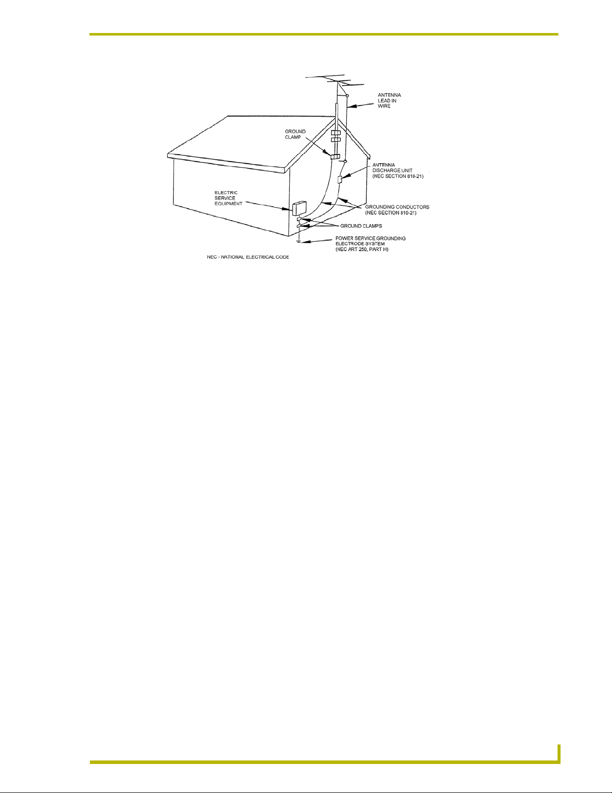
14. Outdoor Antenna Grounding - If an outside antenna or cable system is connected to the
product, make sure the antenna or cable system is grounded to provide some protection against
voltage surges and built-up static charges (FIG. 1). Article 810 of the National Electrical Code,
ANSI/NFPA 70, provides information regarding proper grounding of the mast and supporting
structure, grounding of the lead-in wire to the antenna discharge unit, size of grounding
conductors, location of antenna-discharge unit, connection to grounding electrodes, and
requirements for the grounding electrode.
b
PLB-AS16 16 x 16 Stereo Audio Switcher
Page 5
Safety Instructions
FIG. 1 Outdoor antenna grounding
15. Lightning - For added protection for this product during lightning storms, or when the product
is left unattended and unused for long periods of time, unplug it from the wall outlet or other
power source and disconnect other wires, such as an antenna or cable system. This will prevent
damage to the product due to lightning and power line surges.
16. Power Lines - An outside antenna system should not be located in the vicinity of overhead
power lines or other electrical light or power circuits, or where it can fall into such power lines
or circuits. When installing an outside antenna system, extreme care must be taken to keep
from touching such power lines or circuits, as contact with them might be fatal.
17. Overloading - Do not overload wall outlets, extension cords, or integral convenience
receptacles, as this can result in a risk of fire or electrical shock.
18. Object and Liquid Entry - Never push objects of any kind into this product through openings,
as they may contact dangerous voltage points or short out parts, resulting in a fire or electrical
shock. Never spill any kind of liquid on this product.
19. Servicing - Do not attempt to service this product yourself, as opening or removing covers
may expose you to dangerous voltage or other hazards. Refer all servicing to qualified service
personnel.
20. Damage Requiring Service - Unplug this product from the wall outlet or other power source.
Refer servicing to qualified service personnel under the following conditions:
a. When the power supply cord or plug is damaged.
b. If liquid has been spilled on the product or if objects have fallen into the product.
c. If the product has been exposed to rain or water.
d. If the product does not operate normally by following the operating instructions, adjust
only those controls that are covered by the operating instructions. An improper adjustment
of other controls may result in damage and will often require extensive work by a qualified
technician to restore the product to its normal operation.
e. If the product has been dropped or damaged in any way.
f. When the product exhibits a distinct change in performance. This indicates a need for
service.
LB-AS16 16 x 16 Stereo Audio Switcher
c
Page 6

Safety Instructions
21. Replacement Parts - When replacement parts are required, make sure the service technician
has used replacement parts that are specified by the manufacturer or have the same
characteristics as the original parts. Unauthorized substitutions may result in fire, electrical
shock, or other hazard.
22. Safety Check - Upon completion of any service or repairs to this product, ask the service
technician to perform safety checks to determine that the product is in proper operating
condition.
23. Wall or Ceiling Mounting - The product should be mounted to a wall or ceiling only as
recommended by the manufacturer.
24. Heat - The product should be situated away from heat sources, such as radiators, heat registers,
stoves, or other products (including amplifiers) that produce heat.
d
PLB-AS16 16 x 16 Stereo Audio Switcher
Page 7

Table of Contents
Table of Contents
Safety Instructions ...................................................................................................a
Product Information .................................................................................................1
PLB-AS16 Specifications .................................................................................................. 2
Connection and Power-Up Procedure............................................................................... 2
PHASTLink Ports .............................................................................................................. 2
Line-Level Inputs ............................................................................................................... 2
Line-Level Outputs ............................................................................................................ 3
Note on Intercoms ............................................................................................................. 3
PHASTLink Cable Information ................................................................................5
Building a Double 120-ohm Terminator............................................................................. 6
PhastLink Connections...................................................................................................... 7
LB-AS16 16 x 16 Stereo Audio Switcher
i
Page 8

Table of Contents
ii
PLB-AS16 16 x 16 Stereo Audio Switcher
Page 9
Product Information
PHAST Landmark Audio Switches distribute stereo program and monaural intercom audio for
whole-house sound integration. Operating via the PHASTLink data bus, Landmark Audio Switches
respond to keypads, panels, or system automation-routing any input to any output.
Each channel has automated audio pre-amp processing for volume level, balance, bass, treble,
loudness, and muting. Interactive feedback is provided for these parameters, plus routing and signal
sensing. Each input has signal sensing capability, allowing program events to be triggered by an
input signal state.
Inputs can be configured as a stereo pair, or as a mono input, such as for an intercom input. The
PLB-AS16 provides programmable switching capabilities for 16 stereo outputs and 16 stereo
inputs (or 32 mono inputs).
16 full audio zones are supported. Each output is an audio zone, and each zone can select any input,
even if that input is already selected by another audio zone.
Landmark software now allows you to automatically software-connect any audio source to inputs
on ALL of the Audio Switches in a system. This allows multiple Audio Switches to share the same
sources, increasing the number of audio zones in a system that use those sources.
Product Information
Each Audio Switch provides 16 audio zones. Intercom capabilities are limited to one Audio Switch,
with a maximum of 16 intercom zones (out). Landmark software does not limit the number of
Audio Switches in a system, although switching all zones on multiple Audio Switches will slow
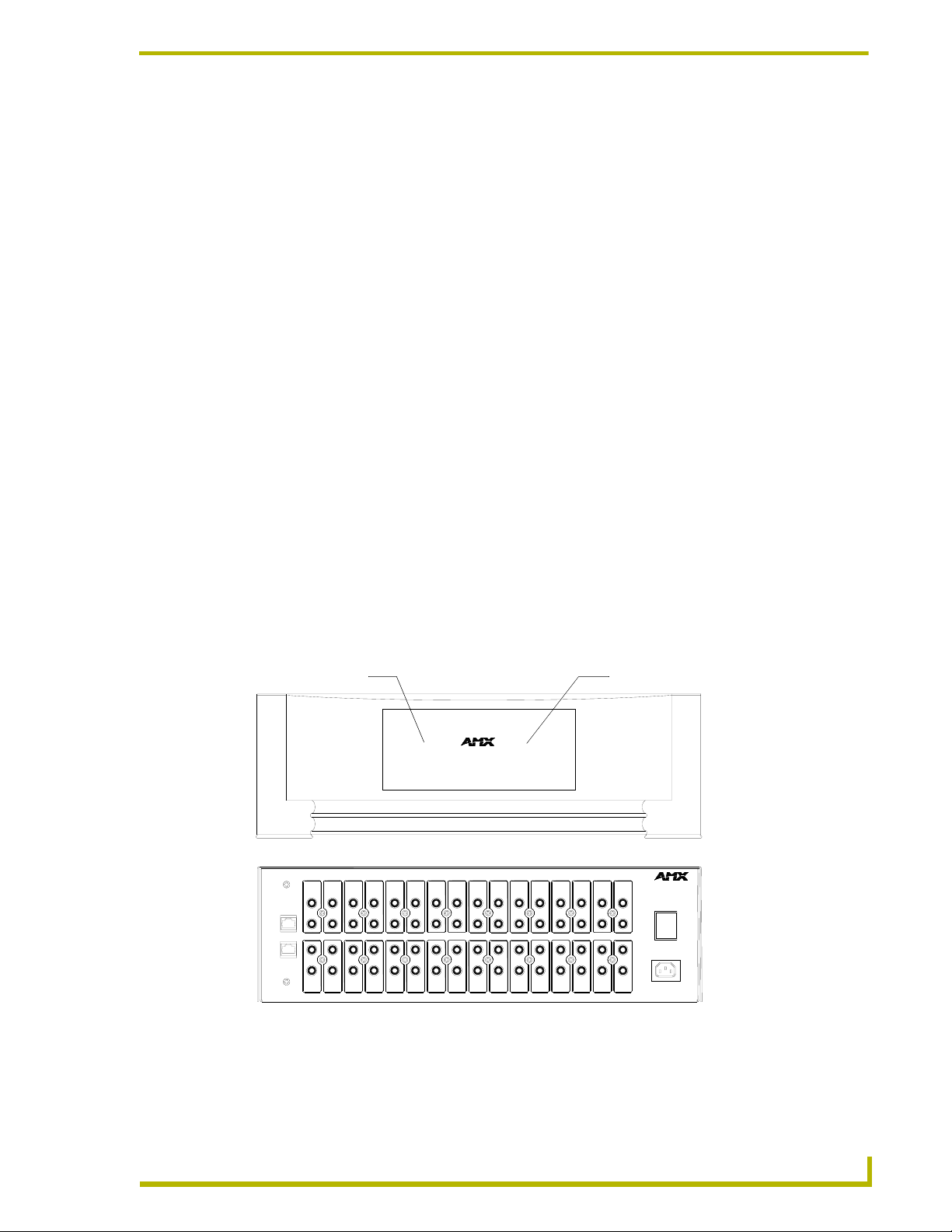
down the switch response time. Landmark audio switches can be rack or shelf mounted. The rear
panel of the PLB-AS16 is shown in .
14 15
Link LED (red)
16
LEFT
IN
I
RIGHT
O
POWER
LEFT
OUT
RIGHT
AC
PLB-AS16 front view
PLB-AS16 rear view
Power LED (green)
31 2 4 5 6 7
k
n
P
i
s
h
L
a
t
12
POWER
4567
PLB-AS16 16 x 16 STEREO AUDIO SWITCHER
8
83
139 10 11 12
139101112 14 15 16
FIG. 1 PLB-AS16 16 x 16 Stereo Audio Switcher (front and rear views)
LB-AS16 16 x 16 Stereo Audio Switcher
1
Page 10

Product Information
PLB-AS16 Specifications
PLB-AS16 Specifications
Powe r • DOMESTIC versions - 115 VAC, 60 Hz
• INTERNATIONAL version - 230 VAC, 50/60 Hz
Channels 16 stereo channels
Inputs 32 RCA line level inputs
Outputs 32 RCA line level outputs (16 stereo pairs)
Intercoms 16 intercom (out) zones (16 maximum per Landmark system)
Level Steps 100-step resolution
LEDs • Power LED (green)
• Link LED (red) - Indicates ID on a netrwork
• Zone-active LEDs (1-16) - conditions are full on, dim, and blinking (used for
ID mode recognition). Light to indicate activity on each zone
Wiring 2 RJ-45 PhastLink ports
Dimensions 5.56" x 17.13" x 15.25" (14.12 cm x 43.51 cm x 38.74 cm)
Weight 16.3 lbs (7.39 kg)
Accessories: PM-RAC Rack-Mount Kit, requires 3 rack spaces (5.25" / 133.3 mm).
Connection and Power-Up Procedure
1. Read the Safety Instructions section at the beginning of this document.
2. Plug the PLB-AS16 power cord into a matching and properly grounded 115 or 230 VAC
outlet.
Verify wether you are using the domestic or international version by checking the
serial number.
The serial number for the domestic version starts with "992-10".
The serial number for the international version starts with "992-11".
3. Turn the PLB-AS16 on. The power switch is located at the right side of the rear panel. On
power-up, 16 "zone-active" LEDs display at the center of the front panel.
PHASTLink Ports
There are two PHASTLink ports on the left side of the rear panel of the PLB-AS16. Usually you
will use only one, but the second port allows you to daisy chain the Audio Switch to other
PhastLink devices, such as additional Landmark Audio Switches or Audio Amplifiers.
It does not matter which PHASTLink port you use; they are both functionally identical.
TERMINATE any unused ports.
Line-Level Inputs
There are 32 stereo line-level RCA-type input jacks on the rear panel of the system unit , providing
16 stereo pairs of audio input.
2
PLB-AS16 16 x 16 Stereo Audio Switcher
Page 11

Product Information
Line-Level Outputs
There are 32 stereo line-level RCA-type output jacks on the rear panel of the system unit, providing
16 stereo pairs of audio output.
Note on Intercoms
An RCA intercom cable from an PLH-MIC Mic Hub may plug into either the Right In or Left In
connector for an Audio Switch channel. In either case, the Right Out and Left Out for that channel
will both carry the same mono signal. In other words, the Right Out and Left Out for a channel
always comprise one audio zone.
It is possible to connect one intercom to a Right In and another to a Left In, but only one of those
intercoms can be switched to the audio zone output at any given time.
LB-AS16 16 x 16 Stereo Audio Switcher
3
Page 12

Product Information
4
PLB-AS16 16 x 16 Stereo Audio Switcher
Page 13

PHASTLink Cable Information
This section contains information that you will need to make PHASTLink cables, plus general
information on connecting PHASTLink devices.
PHASTLink cables are used to connect all PHASTLink-compatible devices, including keypads,
dimmers, J-box IR devices, amplifiers, audio switches, etc. PHASTLink uses a standard 10BaseT
connection (i.e. Cat 5 wire and RJ-45 connectors), and the wire should be connected in the standard
manner illustrated in the following table. If the standard EIA/TIA 568A color code is followed,
wiring problems will be minimized.
PHASTLink Cable Information
Pin # Wire Color Polarity Function
1 White/Green + Transmit
2 Green - Transmit
3 White/Orange - Mic
4 Blue - Ground
5 White/Blue + 12VDC
6 Orange + Mic
7 White/Brown + Receive
8 Brown - Receive
RJ-45 Socket RJ-45 Plug
1
2
3
4
5
PHASTLink Cable Information
6
7
8
1
2
3
4
5
6
7
8
It is important that the correct pairing is observed. Transmit, Receive, and Mic
need to be on twisted pairs. Splitting pairs (e.g., using a white/green wire with a blue/
white wire for transmit) will result in increased crosstalk, and may result in bus failure
or noise on the intercom.
The system comes with a 15-port hub built into the PLB-CF10 cardframe. The maximum length of
PHASTLink wire per port is 1,000 feet.
Each PHASTLink device has two RJ-45 jacks to allow multiple devices to be daisy-chained on one
PHASTLink port. Remember to always terminate the unused RJ-45 jack of the last device (or the
only device) in a chain of PHASTLink devices (see Building a Double 120-ohm Terminator for
details).
The limit for each home run is 500 mA or 10 PHASTLink devices, whichever comes first
(FIG. 4). Extra hubs can be added to provide additional ports.
Only one Landmark LCD keypad (i.e. DMS or IMS) can be used per port, so always
home-run each keypad.
Some PHASTLink devices (particularly those devices that require two-way
communication to the Master) have relatively high bandwidth requirements. These
devices (including SAM modules, the PMB-TCC Remote Television Control Center, and
ITI Printer/Automation Module) should also not be daisy-chained.
ppendix: PHASTLink Cable Information
5
Page 14

PHASTLink Cable Information
To other PHASTLink devices
(up to 500 mA total, or 10 devices whichever comes first)
FIG. 4 500 mA or 10 devices (whichever comes first) max per port.
Building a Double 120-ohm Terminator
For optimum performance, you must install a double 120-ohm terminator in the unused RJ-45 jack
of the last device (or the only device) in a chain of PHASTLink devices.
Up to 15 PHASTLink
connections to a PLB-CF10 Cardframe up to 500 mA per port
hubs for more connections).(add PHAST
PLB-CF10 Cardframe
To build a double 120-ohm terminator:
1. Install a 120-ohm resistor (1/4-watt or larger) between pins 1 and 2 of an RJ-45 connector.
2. Install a 120-ohm resistor (1/4-watt or larger) between pins 7 and 8 of the same RJ-45
connector.
When connecting Landmark keypads that will be used as intercoms, the Microphone Hub taps off
the intercom audio signal carried on the PHASTLink cable from that keypad.
Landmark LCD keypads must connect directly to a Landmark Hub (or Microphone Hub). Due to
power requirements and/or the need for a separate microphone line for each keypad, they cannot be
daisy-chained to other LCD keypads. For maximum performance and reliability, a Landmark
keypad should be the only device on a home run to a port. PHASTLink devices cannot be wired in
a star configuration (see FIG. 5).
PHAST Cardframe or Hub PHAST Cardframe or Hub
FIG. 5 Home-run each Landmark LCD keypad.
6
Appendix: PHASTLink Cable Information
Page 15

PHASTLink Cable Information
PhastLink Connections
FIG. 6 shows how PHASTLink and HubLink ports are connected in a Landmark system.
PLB-CF10 CardFrame
PLH-RPT Hub
12 13 14 15
PHASTLink
Device
PHASTLink
Device
Terminate the
unused port
HubLink
OUT IN
HubLink
OUT IN
PLH-MIC Hub
PHASTLink MIC
DMS
7
8
PHASTLink MIC
Terminate the
unused port
HubLink
OUT IN
FIG. 6 PHASTLink ports connected in a typical Landmark system
ppendix: PHASTLink Cable Information
7
Page 16

AMX reserves the right to alter specifications without notice at any time.
DALLAS, TEXAS • LOS ANGELES, CALIFORNIA • MEXICO CITY, MEXICO • ONTARIO, CANADA • PHILADELPHIA, PENNSYLVANIA • SHANGHAI, CHINA • SINGAPORE • TAMPA, FLORIDA • WESTERLO, BELGIUM • YORK, ENGLAND
3000 RESEARCH DRIVE, RICHARDSON, TX 75082 USA • 800.222.0193 • 469.624.8000 • 4 69-624-7153 fax • 800.932.6993 technical support • www.amx.com
2004 AMX Corporation. All rights reserved. AMX, the AMX logo, the building icon, the home icon, and the light bulb icon are all trademarks of AMX Corporation.
©
051-004-2427 10/04
AMX reserves the right to alter specifications without notice at any time. *In Canada doing business as Panja Inc.
93-2806-91 REV: C
 Loading...